

Page 1

Typ1 osa / CC 220
Diagnosis
Operation, Application
Version
101
Page 2

Typ1 osa / CC 220
Diagnosis
Operation, Application
1070 073 306-101 (91.10) GB
(V25)
E 1991
by Robert Bosch GmbH,
All rights reserved, including applications for protective rights.
Reproduction or handing over to third parties are subject to our written permission.
Discretionary charge 10.– DM
Page 3

Page 4

Flexible Automation
Contents
Contents
1. General 1 – 1. . . . . . . . . . . . . . . . . . . . . . . . . . . . . . . . . . . . . . . . . . . . . . . . . . . . . .
2. Safety instructions − 1 – 1. . . . . . . . . . . . . . . . . . . . . . . . . . . . . . . . . . . . . . . . . . .
3. Calling the diagnostic programs 1 – 2. . . . . . . . . . . . . . . . . . . . . . . . . . . . . . . . .
4. Description of the diagnostic programs
D1 Logbook − D1 – 1. . . . . . . . . . . . . . . . . . . . . . . . . . . . . . . . . . . . . .
D5 Internal reference point offset D5 – 1. . . . . . . . . . . . . . . . . . . . . . .
D6 Interface data D6 – 1. . . . . . . . . . . . . . . . . . . . . . . . . . . . . . . . . . . . .
D7 Communication store display D7 – 1. . . . . . . . . . . . . . . . . . . . . . .
D9 EEPROM management − D9 – 1. . . . . . . . . . . . . . . . . . . . . . . . .
D21 Logic analyzer − D21 – 1. . . . . . . . . . . . . . . . . . . . . . . . . . . . . . . .
D22 Axis oscilloscope − D22 – 1. . . . . . . . . . . . . . . . . . . . . . . . . . . . . .
D23 Contour display − D23 – 1. . . . . . . . . . . . . . . . . . . . . . . . . . . . . . .
D24 Axis optimization D24 – 1. . . . . . . . . . . . . . . . . . . . . . . . . . . . . . . . .
D25 Lead screw error compensation − D25 – 1. . . . . . . . . . . . . . . . .
D26 CNC remote diagnosis (information) D26 – 1. . . . . . . . . . . . . . . .
D27 Putting into operation for circular compensation ‘ D27 – 1. . .
D28 Tapping ‘ D28 – 1. . . . . . . . . . . . . . . . . . . . . . . . . . . . . . . . . . . . . .
CC 220 / 320
Diagnosis
Notes: Diagnostic programs which are not available in the CC 200/300 are identified by
an ‘ in front of the page number.
If a diagnostic program contains new or modified functions – compared with the
controls of the Type CC 200/300 –, this is indicated by a − in front of the page num-
ber.
The following diagnostic programs are intended exclusively for BOSCH service
personnel and are not described in this manual:
D2 Reloading the operating program
D3 Cancelling all memory
Separate manuals are available for the diagnostic programs D4 and D26:
D4 Machine parameter program CC 220 M/T: P. No.: 4201
CC 320 M: P. No.: 4180
D26 CNC remote diagnosis P. No.: 4184
The diagnostic programs
D8 Change language
D10 Library management
implemented in the CC 220/320 are no longer present as special diagnostic programs in controls of the type CC 220/320, but can now be called directly by way
of softkey. Please refer to the appropriate operating manual for operating instructions.
C – 1
Page 5

Flexible Automation
Contents
CC 220 / 320
Diagnosis
C – 2
Page 6

Flexible Automation
1. General
This manual refers to the software version V25 for the controls CC 220/320.
The diagnostic programs D21 to D28 are options which are subject to charge.
2. Safety instructions
Diagnostic programs permit critical changes to be made in the interaction of CNC,
machine and drives right up to complete deletion of the CNC memory.
If they are used by insufficiently trained or untrained personnel, this may thus result
in serious damage to the machine and drives, loss of software or even injury!
For this reason, diagnostic programs must be started and operated only by
correspondingly trained expert personnel.
In this context, please note our extensive range of training courses. You will find
an overview of the available seminars on the inner cover of this manual. Our training center will gladly provide you with further information.
General
CC 220 / 320
Diagnosis
MOVE
MP
In some diagnostic programs, axes have to be traversed in order to optimize CNC
servo loops and drives.
For this reason, make sure that no one enters the machine’s danger area during execution of such diagnostic programs.
The following symbols are used in this manual in order to point out certain things
which are relevant to safety:
Axis movement possible!
For this reason, make sure that there are no persons or objects in the machine’s
danger area.
Make sure that no collisions are possible in the axis traversing range.
Machine parameter record is modified! This is followed by a CNC restart. The modified machine parameters are active after this.
Is there a backup of the original machine parameters?
BOSCH will not be liable for damaging resulting from incorrectly calculated, programmed or optimized machine parameters or non–observance of limit data!
Active axis processor data is modified!
This effects the axis response.
SERVO
Data loss possible!
Data in the user RAM (part programs, tables etc.) may possibly be deleted or over-
DATA
written.
Do you possess a backup of this data?
3. Calling the diagnostic programs
1 – 1
Page 7
Flexible Automation
General
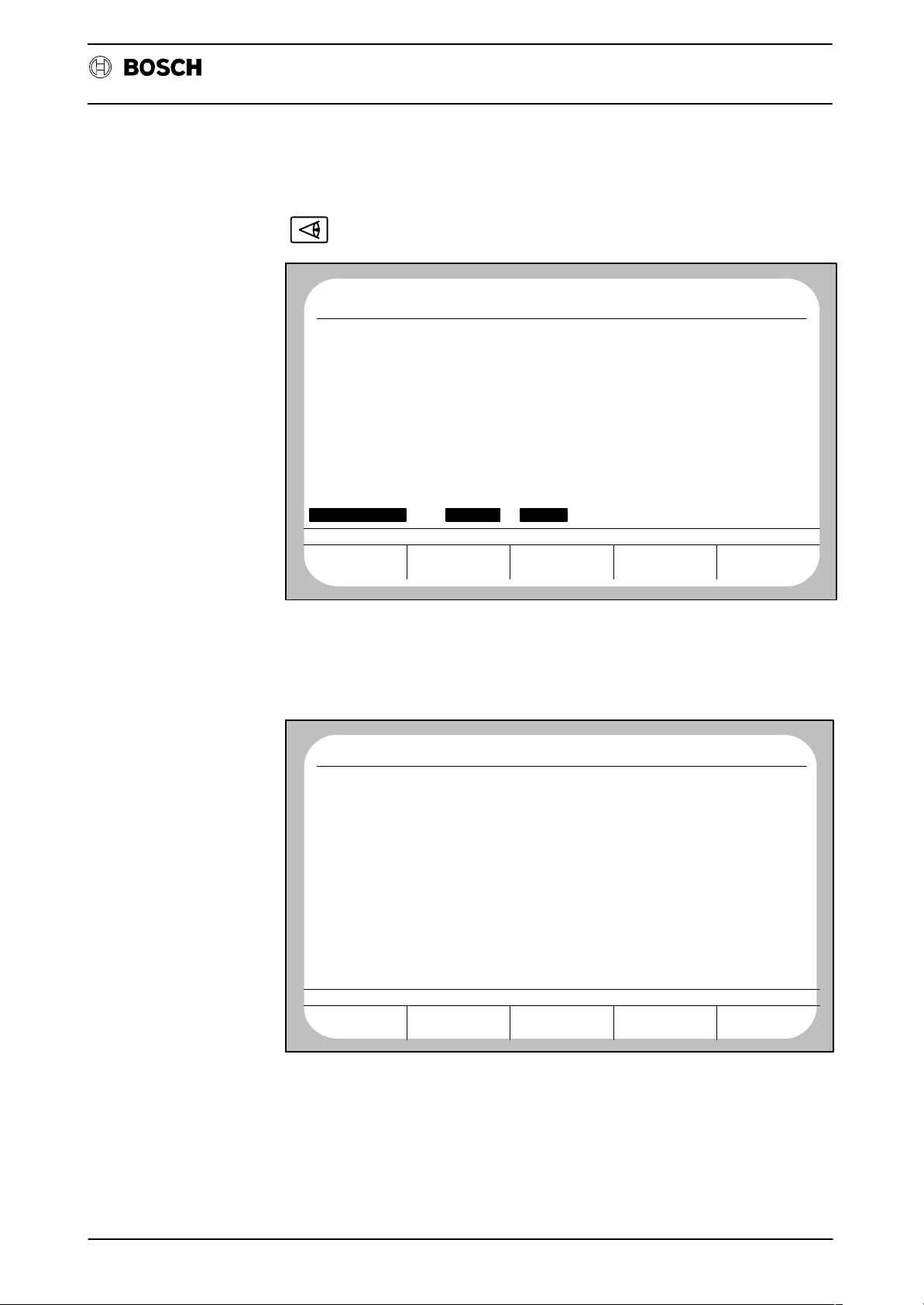
The following monitor display appears after selection of group operating mode
(DIAGNOSTIC):
Diagnosis
CC 220 / 320
No CP0
ERROR CONDITION ON STATUS
AT LAST PROGR.
F 0.0 M 0T 0
DIAGNOSTIC
CONTROL
ACT
DIAGNOSTIC
MACHINE
NC0
STOP
G
90
G
94
G
14
G
15
G
80
G
153
G
39
G
65
G
146
G
994
FUNCTION
G
G
G
G
G
G
130
G
253
G
G
G
115
RESET
66
40
29
62
68
DIAGNOSTIC
12. 5 16:53PROGRAM
G
1
8
71
G
140
G
G
27
G
79
G
53
G
67
G
97
G
99
G
167
DRIVE ON
7
SERVICE
FUNCTION
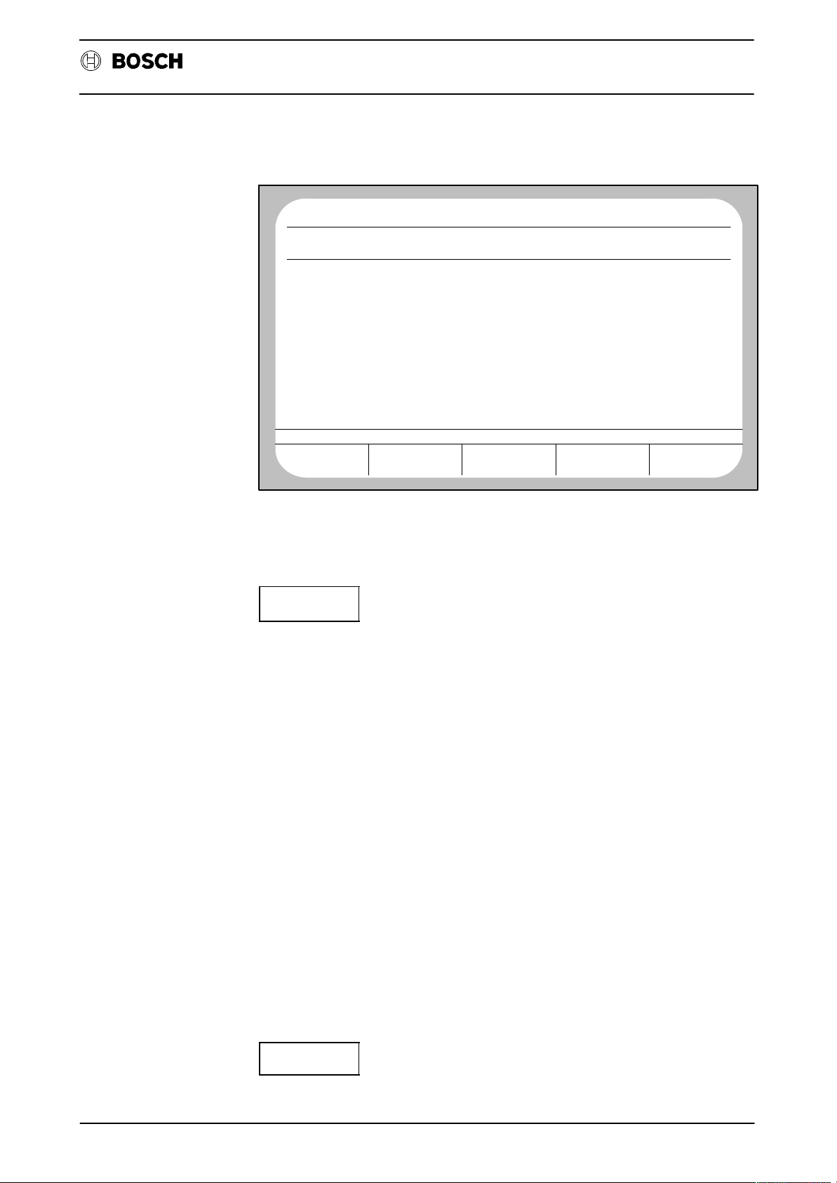
The control displays all available diagnostic programs after operation of the softkey
SERVICE FUNCTION (possibly only after input of a code number; refer to the section ”Notes”):
No CP0
NUMBER PROGRAM NAME LENGTH
D
D
D
D
D
D
D
D
D
D
D
D
D
D
MEMORY USED BY DIAG.:
MEMORY A V AILABLE:
SERVICE FUNCTION
21
22
23
24
25
27
1
2
3
4
5
6
7
9
ACT
LOGBOOK MONITOR
RELOAD OPERATING PROGRAM
CANCEL ALL MEMORY
MACHINE PARAMETER PROGRAM
INTERNAL REF. POINT OFFSET
INTERFACE DATA
COMMUNICATION STORE DISPLAY
MANAGE EEPROM
LOGIC–ANALYZER
AXIS OSCILLOSCOPE
CONTOUR DISPLAY
AXIS OPTIMIZATION
LEAD SCREW ERROR COMPENSATION
PUTTING INTO OPERATION FOR CIRCULAR COMPENSATION
DATA IN DATA OUT START DELETE
NC0
WAIT
DIAGNOSTIC
14.10 8:28PROGRAM
ACCESS
E
E
E
E
E
E
E
E
E
E
E
E
E
E
44384 OTHERS: 2658
2574398
The system asks for the number of the desired program when the softkey START
is pressed. Input of the program number is acknowledged with the ENTER key. The
CNC then starts the corresponding diagnostic program.
1 – 2
Page 8

Flexible Automation
General
Notes:
‘ If the softkey RESET FUNCTION and then softkey CLEAR ALL LOGIC are
pressed in group operating mode DIAGNOSTIC, it is possible to enter the
softkey level SERVICE FUNCTION only by input of a code number as from
this point in time.
When a correct code number has been entered, the softkey level SERVICE
FUNCTION is accessible without input of the code number until renewed operation of the softkey sequence DIAGNOSTIC, RESET FUNCTION, CLEAR
ALL LOGIC.
‘ Some diagnostic programs create files with the group identifier ”L” or ”D” for
recording data. This reduces the memory space which is available for part
programs.
‘ Data recordings can be repeated any number of times within diagnostic pro-
grams, since the previous recording is overwritten by each new recording.
All other operating modes of the control can be used during recording of data
by a diagnostic program.
Exception: CONTROL RESET and selection of a different diagnostic program cancel the currently active diagnostic program (except for D21).
Diagnosis
CC 220 / 320
1 – 3
Page 9

Flexible Automation
General
CC 220 / 320
Diagnosis
1 – 4
Page 10

Flexible Automation
D1 Logbook
4. Description of the diagnostic programs
D1 – Logbook
General
The diagnostic program D1 is used for management of one or more ”logbooks”. A
logbook is a file with the identifier ”D” which contains various data for reconstruction
of operating sequences, error messages or warnings etc. This file is divided into
5 ring memories which store warnings, errors, system errors, other messages and
operating steps in the order of their occurrence.
Activating/deactivating a logbook
There are two possibilities for activation of a logbook:
CC 220 / 320
Diagnosis
‘ Input of a logbook file number in machine parameter P 9914. Then ACTI-
V ATE the machine parameters. The logbook is automatically initialized with
the specified file number after control start–up and is active as from this point
in time. The ring memories are created with the following sizes: R1 to R4:
512 bytes, R5: 0 byte.
‘ Operation of softkey INIT in diagnostic program D1.
An already active logbook can be deactivated in diagnostic program D1 by pressing
softkey INIT, input of ”0” and acknowledgement with the ENTER key or by selection
of a different logbook (also refer to softkey LOGBOOK SELECTION). A logbook
cannot be activated again once it has been deactivated. Only deactivated logbooks
can be deleted.
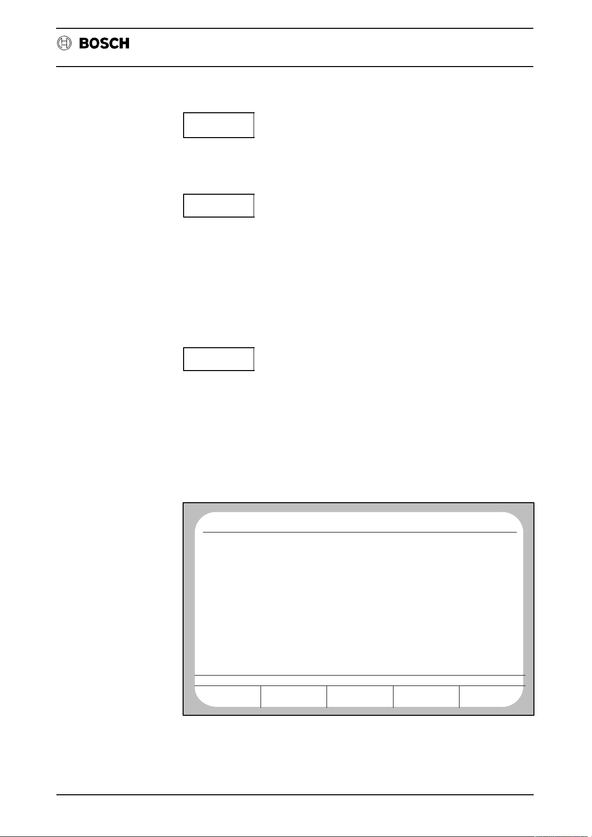
User interface/softkey assignments
The following display appears if no logbook is yet active when D1 is selected:
No CP0
ACT
LOGBOOK NOT INITIALIZED!
NC0
STOP
DIAGNOSTIC
12. 5 16:59
12. 5 16:59PROGRAM
DISPLAY
RING STORE
D1 – 5
INIT
LOGBOOK
SELECTION
LOGBOOK
PUNCHOUT
Page 11
Flexible Automation
D1 Logbook
CC 220 / 320
The following monitor display is shown if a logbook is already active:
Diagnosis
No CP0
PROGRAM
LOGBOOK D 11000 ACTIVE
RING STORE FOR WARNING
RING STORE 2 FOR ERRORS
RING STORE 3 FOR SYSTEM ERRORS
RING STORE 4 FOR OTHER MESSAGES
RING STORE 5 FOR OPERATING STEPS
TEST POINT 1 ADDRESS 0000064
TEST POINT 2 ADDRESS 00000000
TOTAL LOGBOOK SIZE: 605 BYTES
DISPLAY
RING STORE
INIT
ACT
NC0
STOP
INIT
DIAGNOSTIC
12. 5 16:59
SIZE = 100 BYTES
SIZE = 100 BYTES
SIZE = 100 BYTES
SIZE = 100 BYTES
SIZE = 100 BYTES
LOGBOOK
SELECTION
LOGBOOK
PUNCHOUT
Initialization of a logbook (creation of a new logbook file).
When the softkey INIT is pressed, the CNC expects input of a logbook file number
(value range 0.3000–999999999).
Input of ”0” deactivates a currently active logbook (”active” means that recordings
take place in this logbook). A logbook cannot be activated again once it has been
deactivated. Only deactivated logbooks can be deleted.
Two test points are interrogated after input of the file number. However, these are
of importance only for service purposes. Skip test point input by pressing the ENTER key twice.
The system then asks for the memory size for the individual ring stores. Reservation of approx. 500 bytes per ring store will already permit a sensible recording to
be made.
After this, the logbook is initialized and automatically activated. Any events which
occur are recorded from this point in time onwards.
The number of logbooks which can be created is limited by the available memory
space. Only one logbook can be active at any time.
In order to use the file number of a deactivated logbook again for an active logbook,
it is first necessary to delete the deactivated logbook in the softkey level SERVICE
FUNCTION and to then create a logbook again in D1 under softkey INIT.
LOGBOOK
SELECTION
Selection of any existing deactivated logbooks for display on the monitor.
D1 – 6
Page 12

Flexible Automation
D1 Logbook
CC 220 / 320
Diagnosis
LOGBOOK
PUNCHOUT
The currently displayed logbook is output on an external data medium. The current
setting in group operating mode DATA I/O, softkey DATA OUT, determines via
which interface output takes place. A change in operating mode aborts active output. Output via the DNC interface is not possible.
DISPLAY
RING STORE
This softkey results in display of the contents of the individual ring stores. The store
contents are displayed in plain text with data, time and message.
Example: Ring store 1 (warnings):
No CP0
PROGRAM
LOG 11 23.05 09:31 WARNING: DATA PROTECTED
KEYING: DATA SK1+ SK1− 0 ENTR
TEST POINT: 1=00000000 2=00000000 MODE: DATA
LOG 7 16.05 11:34 WARNING: AXIS MOVING
KEYING: SK5+
TEST POINT: 1=00000000 2=00000000 MODE: DIAGNOSTIC
DISPLAY END
PAG E
FORWARDS
ACT
NC0
STOP
1
SK5− DIAG SK3+ SK3− SK3+
PAG E
BACK
LAST
KEY
Example: Ring store 5 (operating steps):
No CP0
SK4−
ERET
SK4−
DIAG
SK4+
SK3+
SK4+
SK5−
SK5+
2
SK3+
ENTR
SK2+
SK4−
SK4+
ERET
SK4+
SK4−
2
SK4−
SK3−
SK5+
ERET
SK1−
DATA
5
SK1−
SK4+
ERET
SK4−
SK4+
5
SK4+
SK3+
ENTR
SK4−
SK1+
SK2−
SK1−
SK1+
ENTR
ACT
ERET
SK4+
ENTR
2
SK4−
DIAG
0
SK4+
SK3−
SK2+
SK1+
ENTR
2
NC0
STOP
RESET
ENTR
6
SK4−
SK4+
ERET
2
SK3−
SK3+
SK1−
ERET
1
SK4−
SK3+
6
5
SK4+
DIAG
SK5−
SK1−
SK3+
SK5−
SK1+
SK2−
SK1−
SK4+
ENTR
SK3−
5
RESET
2
DIAG
DATA
SK5+
SK1+
SK5−
SK5+
SK1−
SK2+
SK1+
ERET
SOFTKEY
MASK
1
SK3+
2
SK3+
7
SK3−
RESET
ENTR
SK1−
SK5+
SK1−
SK1+
SK1−
ENTR
SK4−
DIAGNOSTIC
DIAGNOSTIC
12. 5 17: 5PROGRAM
SK4−
DIAG
7
SK3−
2
SK3+
SK5+
0
SK1+
ENTR
SK1+
SK1−
SK1+
3
SK4+
SK4+
ERET
2
SK3+
SK4−
SK3−
SK4−
1
SK5−
0
SK3−
SK1+
SK2−
3
SK4−
PAG E
FORWARDS
PAG E
BACK
The last–pressed key is shown at the top left in the uppermost data line of the monitor (”ENTR” here in the example).
D1 – 7
Page 13

Flexible Automation
D1 Logbook
The following abbreviations are used for display of the keys:
ABAR, MDI, MASC, DATA, DIAG, KORR Group operating modes
CUP+, CDN+, CRI+, CLE+ Cursor keys pressed
CUP–, CDN–, CRI–, CLE– Cursor keys released
LPE+ Magnifier pressed
LPE– Magnifier released
SK1+, SK2+, SK3+, SK4+, SK5+ Softkey pressed
SK1–, SK2–, SK3–, SK4–, SK5– Softkey released
ERET Level return
DEL Delete key
ENTR Enter key
1 ... 0 Numeric keys
: * – + = Arithmetic operation keys
+/– Sign change
. Decimal point
RESET Stands for Control Reset,
CAL = System error 1
NC reset, switching on/off,
Logbook Init
?? Unknown key code
CC 220 / 320
Diagnosis
SOFTKEY
MASK
The softkey mask present at the time of the entry is displayed. If the key assignment
is displayed by a number, this indicates variable softkey designations, such as occur, for example, for wool sub–tables.
D1 – 8
Page 14

Flexible Automation
D5 – Internal reference point offset
D5 Internal reference point offset
CC 220 / 320
Diagnosis
The currently active axis offset values are displayed after selection of the program
D5.
These may have been generated by G92 or by ZERO SET. Zero offsets by way of
G54 – G59, G154 – G159, G254 – G259, G60 or G160 are not taken into account
here.
No CP0
AXIS
X
Y
Z
ACT
OFFSET VALUE
767.766 MM
− 715.692
124.423
NC0
WAIT
MM
MM
DIAGNOSTIC
14.10 8:32PROGRAM
D5 – 9
Page 15

Flexible Automation
D5 Internal reference point offset
CC 220 / 320
Diagnosis
D5 – 10
Page 16

Flexible Automation
D6 – Interface data
General
User interface/softkey assignments
D6 Interface data
CC 220 / 320
Diagnosis
Data arriving at the standard interfaces can be displayed with D6. The data is not
stored during this operation.
No check is made of the data (e.g. with respect to correct file header, program end,
ECODE etc.). Reading–in is not subject to any time monitoring function. No mes-
sage is issued if data transfer is faulty.
The following functions are offered after program selection:
DEVICE
SELECT
DEVICE
SELECT
STATUS
DFS
SEARCH
DFS–NO.
SEARCH
START
Selection of the data interface and definition of the connected peripheral device.
STATUS
The following softkey bar appears when STATUS is pressed:
SW
CONTROL
SW
CONTROL
HEX CHAR/HEX CHAR/SYMB
Activation/deactivation of the XON/XOFF protocol.
Softkey is shown inverted: software handshake active (Xon/Xoff).
Softkey is displayed normally: hardware handshake active (DTR/DSR).
HEX
Display of the incoming data in HEX format.
CHAR/HEX
Incoming data is displayed as ASCII characters. Exception: display of control characters occurs in HEX format.
CHAR/SYMB
Incoming data is shown as ASCII characters. Exception: control characters are displayed symbolically (e.g. <SP> = Space, <LF> = Line Feed).
D6 – 11
Page 17
Flexible Automation
D6 Interface data
CC 220 / 320
Diagnosis
START
Start of the reading–in operation. This operation continues until the screen is full.
Half of the screen is filled again in each case by repeated operation of this key.
DFS
SEARCH
Reading–in is started by pressing the softkeys DFS SEARCH and START and is
then continued until a correct DFS identifier is found. After this, a maximum of 17
lines of the program/table are displayed. The rest of the incoming program/table
data of this file is skipped after renewed operation of DFS SEARCH and then
START. The control displays the first 17 lines of the program/table again only after
the next DFS identifier has been found.
Note: ”DFS search” is active as long as the softkey is shown inverted. The function
is executed only if the DFS identifier is correctly received.
DFS–NO.
SEARCH
The system asks for the file number for which a search is to be made after operation
of this softkey. After input of this number and subsequent operation of the softkey
START, reading–in takes place until the specified file number (DFS identifier) is
found. The incoming data is displayed only after this has occurred.
Note: ”DFS search” is active as long as the softkey is displayed inverted. The
function is executed only if the DFS identifier is received correctly.
Example: Display of read–in data in the format CHAR/HEX:
No CP0
<13><12><00><00><00><00><00><00><00><00><00><00><00><00><00><00><00
<00><00><00><00><00><00><00><00><00><00><00><00><00><00><00><00><00
<00><00><00><00><00><00><00><00><00><00><00><00><00><00><00><00><00
<00><00><00><00><00><00><00><00><00><00><00><00><00><00><00><14><12
<00><00><00><00><00><00><00><00><00><00><00><00><00><00><00><00><00
<00><00><00><00><00><00><00><00><00><00><00><00><00><00><00><00><00
<00><00><00><00><00><00><00><00><00><00><00><00><00><00><00><00><00
<00><00><02><0D><0A>
<14><12>(DFS,P 55555,TEACH IN 18.08,RWED)<
D><0A>
<14><12>1 A%=3:REM NUMBER OF AXES <0D><0A>
1 A1$="X":REM AXIS ADDRESS<0D><0A>
1 A2$="Y"<0D><0A>
1 A3$="Z"<0D><0A>
1 A4$="B"<0D><0A>
1 A5$="B"<0D><0A>
1 <14><12>B%=250:REM INTERFACE OUTPUT FOR SETTING MODE
ACTIVATION <0D><0A>
INTERFACE DATA
DEVICE
SELECT.
ACT
STATUS
NC0
WAIT
DFS−
SEARCH
DFS−No.
SEARCH
DIAGNOSTIC
14.10 8:40PROGRAM
START
D6 – 12
Page 18
Flexible Automation
D7 – Communication store display
General
D7 Communication store display
CC 220 / 320
Diagnosis
The content of the communication store from the point of view of the PLC can be
displayed on the monitor of the CNC in hexadecimal format using the diagnostic
program D7. D7 is offered only if word coupling exists between the CNC and PLC.
The communication store is a 128 KByte dual port RAM area on the NC–PLC–word
module (WK3). Both the CNC and the PLC (PC 600) have read and write access
to this area.
Start address Page 0
End address Page 0
Start address Page 1
End address Page 1
User interface/softkey assignments
After D7 is started, the control always displays the communication store content
from address C000 H to C07F H (address information as hexadecimal numbers
from the point of view of the PLC):
No CP0
C00 C01 C02 C03 C04 C05 C06 C07
0002
E752
E852
E010
E73E
E746
E952
F000
EA26
F006
F026
F0BA
E000
0000
F092
BB00
C000 COMMUNICATION STORE DISPLAY
C400
F212
F24C
F04E
E95E
0000
0000
0000
0000
0000
0000
0000
0000
0000
0000
0000
*000 0*00 00*0
ACT
0000
0000
0000
0000
0000
0000
0000
0000
0000
0000
0000
0000
0000
0000
0000
0000
NC0
WAIT
0000
0000
0000
0000
0000
0000
0000
0000
0000
0000
0000
0000
0000
0000
0000
0000
BC34
BC34
0000
0000
0000
0000
0000
0000
0000
0000
0000
0000
0000
0000
0000
0000
8000 H
FFFF H
8000 H
FFFF H
0000
0000
0000
0000
0000
0000
0000
0000
0000
0000
0000
0000
0000
0000
0000
0000
.
.
.
.
.
.
.
.
.
.
0000
0000
0000
0000
0000
0000
0000
0000
0000
0000
0000
0000
0000
0000
0000
0000
Page 0
Page 1
0000
0000
0000
0000
0000
0000
0000
0000
0000
0000
0000
0000
0000
0000
0000
0000
BACKUP PAG E 1
DIAGNOSTIC
17.10 14: 0PROGRAM
0
1
2
3
4
5
6
7
8
9
A
B
C
D
E
F
PAG E 0*ADVANCE
128 data words (256 bytes) can be displayed on one screen page. The data is displayed in a table form (8 columns of 16 lines each). It is possible to see the assign-
D7 – 13
Page 19
Flexible Automation
D7 Communication store display
CC 220 / 320
Diagnosis
ment between the displayed data words and their addresses in the communication
store by way of the inversely displayed bars above and on the right of the table.
The three most significant positions of an address (e.g. ”C02” of address ”C02F”)
are shown in the top, highlighted bar, while the least significant position is shown
in the bar on the right of the table (e.g. ”F” of the address ”C02F”).
The address of the top left data word is displayed in the prompt line (here in the
example: ”C000 COMMUNICATION STORE DISPLAY”).
Example:
No CP0
C00 C01 C02 C03 C04 C05 C06 C07
0002
E752
E852
E010
E73E
E746
E952
F000
EA26
F006
F026
F0BA
E000
0000
F092
BB00
C000 COMMUNICATION STORE DISPLAY
C400
F212
F24C
F04E
E95E
0000
0000
0000
0000
0000
0000
0000
0000
0000
0000
0000
*000 0*00 00*0
ACP
0000
0000
0000
0000
0000
0000 0000
0000
0000
0000
0000
0000
0000
0000
0000
0000
0000
Address C025 H Address C046 H
NC0
WAIT
0000
0000
0000
0000
0000
0000
0000
0000
0000
0000
0000
0000
0000
0000
0000
0000
BC34
BC34
0000
0000
0000
0000
0000
0000
0000
0000
0000
0000
0000
0000
0000
0000
0000
0000
0000
0000
0000
0000
0000
0000
0000
0000
0000
0000
0000
0000
0000
0000
0000
0000
0000
0000
0000
0000
0000
0000
0000
0000
0000
0000
0000
0000
0000
BACKUP PAG E 1
0000
0000
0000
0000
0000
0000
0000
0000
0000
0000
0000
0000
0000
0000
0000
0000
DIAGNOSTIC
17.10 14: 0PROGRAM
0
1
2
3
4
5
6
7
8
9
A
B
C
D
E
F
PAG E 0*ADVANCE
Search for an arbitrary address
Select the required memory area by means of the softkey PAGE 0/PAGE1. The currently displayed memory area is shown inverted on the softkey.
The individual digits of the address displayed in the prompt line can be incremented
or decremented by means of the three softkeys *000,0*00 and 00*0. The asterisk
on the softkey indicates the position which is changed.
The least significant address need not be specified, since all 16 possible addresses
are displayed underneath each other in one column.
It is possible to switch between incrementation and decrementation of the corresponding position by means of the softkey ADVANCE/BACKUP. The active condition is shown inverted.
D7 – 14
Page 20

Flexible Automation
D7 Communication store display
Example:
You are on Page 0. The prompt line shows the address C000 H.
You are looking for the content of the address D123 H on Page 0.
Switch to ”Increment” (the field ADVANCE on the softkey ADVANCE/BACKUP is
then shown inverted).
Press the softkey *000 once.
Press the softkey 0*00 once.
Press the softkey 00*0 twice.
The 4th data value (from the top) in the left column now shows the content of address D123 H.
CC 220 / 320
Diagnosis
D7 – 15
Page 21

Flexible Automation
D7 Communication store display
CC 220 / 320
Diagnosis
D7 – 16
Page 22

Flexible Automation
D9 – EEPROM management
General
D9 EEPROM management
CC 220 / 320
Diagnosis
The MEM5 memory module (or CP/MEM4 in the case of CC220) contains a 32
KByte EEPROM area as standard (optionally 64 KBytes).
Important data should be saved in the EEPROM since the content of the EEPROM
area is not lost – in contrast to the RAM area – after a total power failure on the MEM
module or after forced backup loading.
The following files can be written into the EEPROM area and read out again using
the diagnostic program D9:
Part programs
LSEC tables
W tables
Zero offset tables
Compensation tables
Machine parameters.
For example, it is then possible to choose whether machine parameters and tables
are to be copied back from the EEPROM to the RAM when the control is put into
operation again.
User interface/softkey assignment
After D9 has been started, the monitor displays a list of all files stored in the EEPROM area.
Each entry in the list additionally contains information as to whether a file with the
same name already exists in the RAM area (column ”IN RAM”) and whether this
file also contains the same data (column ”EQUAL”).
No CP0
LIST OF PROGRAMS TO BE SPECIFIED
No PROGRAM NAME IN RAM EQUAL
0
1
P
2
P
3
P
4
P
ACT
3000
3001
3002
1131
NC0
WAIT
MACHINE PARAMETER
MAIN PROGRAM MOD. DIA 18.08
SR SELECT MODULE
SR TEST DIAGNOSTIC CHANNEL
SR CP
22.06
02.07
22.01
DIAGNOSTIC
14.10 8:45PROGRAM
YES
YES
YES
YES
YES
NO
NO
NO
NO
NO
MEMORY USED BY PROGRAM:
MEMORY AVAILABLE: :
MANAGE EEPROM
MACHINE
PARAMETER
PROGRAM
SELECTION
5409
22239
DELETE COPY
OTHERS: 3224
EEPROM
PROGR.
This list can now be extended by new entries or be shortened by deleting entries.
The functions PROGRAM EEPROM and COPY (from EEPROM to RAM) refer
to the files displayed here!
If it is wished to store files in addition to the files which are already contained in the
EEPROM, it is not necessary for files which are already stored in the EEPROM to
also be present in the RAM for programming of the EEPROM.
D9 – 17
Page 23

Flexible Automation
D9 EEPROM management
CC 220 / 320
Diagnosis
The following functions can be initiated by means of the softkeys:
MACHINE
PARAMETER
The currently active machine parameter record (not file L444!) is incorporated in
the list under number ”0”.
A machine parameter record stored in the EEPROM can be copied into the RAM
area again only if the softkey FROM EEPROM is selected when reloading the complete operating system (diagnostic program D2).
File L444 must be stored in the EEPROM (by means of the softkey PROGRAM
SELECTION) if it i s w i shed to permit restoration of machine parameters without reloading the complete operating system.
PROGRAM
SELECTION
PROGRAM
ALL
PROGRAMS
NEXT
GROUP
PREVIOUS
GROUP
Files can be entered in the list from the groups P, L, V, K, W after pressing PROGRAM SELECTION.
To do this, first select the desired file group with the softkeys NEXT GROUP or
PREVIOUS GROUP. The control then shows you all existing files of the selected
group.
All files of this group can be included in the list by pressing the softkey ALL PROGRAMS.
The softkey PROGRAM permits selection of a single file.
Notes:
‘ When programs are entered in the list, the CNC checks whether the size of
the EEPROM area is sufficient for later programming. If not, the error mes-
sage ”MEMORY FULL” appears in the prompt line.
‘ Link files cannot be included in the list.
‘ The K1 table must not be stored in the EEPROM.
DELETE
DELETE LIST ENTRIES
PROGRAM
ALL
PROGRAMS
D9 – 18
Page 24

Flexible Automation
DATA
D9 EEPROM management
CC 220 / 320
Diagnosis
It is possible to delete either individual entries or all entries in the list. This function
relates only to modification of the displayed list! If it is wished to delete a file
in the EEPROM, it is first necessary to delete the corresponding file in this list. The
EEPROM must then be reprogrammed with the thus modified list. Files existing in
the EEPROM are then possibly overwritten by newer file versions (which are contained in the RAM).
If an individual list entry is deleted (by means of the softkey PROGRAM), it is necessary to enter not the file number but the list number of the corresponding file (column ”NO”) and confirm this with the ENTER key.
COPY
COPY FILES FROM EEPROM
PROGRAM
ALL
PROGRAMS
Files can be copied from the EEPROM area to the RAM area of the control by
means of the function COPY.
All files entered in the list are copied into the RAM after operation of the softkey ALL
PROGRAMS.
If you wish to copy an individual file (by means of the softkey PROGRAM), you must
enter the list number of the corresponding file (column ”NO”) after operation of the
softkey PROGRAM and then confirm this with the ENTER key.
Notes:
‘ Copying of the machine parameter record (list entry ”0”) to the RAM area
is not possible using this function. A machine parameter record stored in the
EEPROM can be copied into the RAM area again only if the softkey FROM
EEPROM was selected when reloading the operating system.
‘ The function COPY is protected by a code.
EEPROM
PROGR.
Programming the EEPROM area with the files entered in the list.
The system first asks for input of a code in order to prevent unintentional programming.
After this, the operator can enter an identifier consisting of a maximum of 50 ASCII
characters. This identifier is of no significance in the current software version. If it
is wished to start programming, skip input of the identifier by pressing the ENTER
key. However, if it is wished to abort the function EEPROM PROGRAMMING at this
point, simply press the level return key.
D9 – 19
Page 25

Flexible Automation
DATA
D9 EEPROM management
The softkey EEPROM PROGR. is displayed inversely during programming. CNC
operation is not possible during this time. The message ”PROGRAMMING IS AC-
TIVE!” flashes in the prompt line. The number of programmed bytes is displayed
continuously. An asterisk appears in front of the list number of a file as soon as this
file has been completely programmed.
The list is moved up on the screen if not all previously programmed files can be displayed on one screen page.
CC 220 / 320
Diagnosis
D9 – 20
Page 26

Flexible Automation
D21 – Logic analyzer
General
D21 Logic analyzer
CC 220 / 320
Diagnosis
The logic analyzer permits recording of a maximum of 16 signals of the CNC–PLC
interface.
During a recording, 500 sampling operations of all selected signals (refer to softkey
CHANNEL SELECTION) are always stored. The interval between two sampling
steps is adjustable.
File D121 is used to record the data. If this file does not yet exist, the system creates
it automatically before a recording (file size: approx. 2 – 2.5 KByte part program
memory). An existing file D121 is overwritten by each new recording.
In addition, recorded data (including the current logic analyzer settings at the time
of recording) or arbitrary logic analyzer settings can also be stored in separate files
for possible subsequent use (refer to softkey FILE SELECTION).
Functional principle of the logic analyzer:
0 ...................500 (Sampling steps)
Trigger
position
Memory
Trigger condition Comparator Clock
Delay
Data stream
Clock
D21 – 21
Page 27

Flexible Automation
User interface/softkey assignments
D21 Logic analyzer
The following display appears after selection of D21:
CC 220 / 320
Diagnosis
No CP0
LOGIC−ANALYZER
WAITING
STARTING VALUES
CHANNELS 8
STORE
CLOCK
TRIGGER−POS.
DISPLAY
STARTING
VALUES
STARTING VALUES
CHANNELS
8 OR 16
POSITION
ACT
LOGIC−ANALYZER STATUS
500 CLOCKS
1 PLC−CY
250 CLOCKS
CHANNEL
SELECTION
TRIGGER
NC0
WAIT
No TYPE ADDR. BIT TRIGGER COND.
0 I 40.7 1
1 O
2 O
3 O
4 O
5 O
6 O
7 O
STARTING
VALUES
CHANNELS
36.0
36.1
36.2
36.3
36.4
36.5
36.6
FILE
SELECTION
*
*
*
*
*
*
*
CLOCK
DIAGNOSTIC
13. 5 8:57PROGRAM
START
RECORDING
The functions of the logic analyzer can be adapted to the respective task by means
of these softkeys:
CHANNELS
8 OR 16
It is possible to record 8 or 16 channels simultaneously. The number of channels
can be set to 8 or 16 by means of this softkey.
TRIGGER
POSITION
You define here how many sampling steps are to be stored before occurrence of
the trigger event.
500 sampling steps are always stored in total in the recording file.
Examples:
Trigger position = 250:
The sampling step executed when the trigger event occurs is assigned the ”num-
ber” 250. A further 250 sampling steps (500 – 250) are then stored additionally as
from this point.
Trigger position = 10:
The sampling step executed when the trigger event occurs is assigned the ”num-
ber” 10. A further 490 sampling steps (500 – 10) are then stored additionally as from
this point.
D21 – 22
Page 28

Flexible Automation
D21 Logic analyzer
CLOCK
CC 220 / 320
Diagnosis
Specification of the time interval between two sampling steps. It is possible to set
three different types of time interval here. In addition, it is necessary to enter the
size of an individual time interval. The following table provides an overview of the
possible inputs:
Interval type Size Meaning
1 (MS) 1 ms – 50 ms Channels can be sampled at ms inter-
vals.
Possible interval size:
1 ms to 50 ms, depending on set size.
2 (TASKS) 1 – 9999 The channels can be sampled on the
basis of task changes. This type of interval is relevant only for users who
possess extremely good system knowledge of the control.
3 (PLC CYCLES) 1 – 9999 The channels can be sampled each
time the PLC performs a ”PE”.
(Possible interval size: time from PE to
PE.)
(Possible only for PIC 250 or word–
coupled PC 600).
CHANNEL
SELECTION
INPUT OF CHANNEL AND TRIGGER CONDITION
PLC INPUTIPLC OUTPUTOPLC MARKER
M
STORE
S
TRIGGER
CONDITION
Select the channel number to be changed (0 – 7 or 0 – 15) with the cursor keys
after operation of CHANNEL SELECTION. It is then possible to assign an
input, output, marker or memory address to the selected channel number by means
of softkey and numeric input. The input must be acknowledged with the ENTER
key.
Setting the trigger condition:
Selection of the channel number with the cursor keys
. The active channel
is shown inverted.
Input of 0 results in low–level triggering,
1 results in high–level triggering,
* (multiplication symbol) No trigger.
An input, output, marker or memory bit is assigned to the active channel by pressing the corresponding softkey (1 – 4) and subsequently making a numeric input.
The following input values are permitted:
Input/output: bits 0.0 to 255.7
Marker: markers 0.0 to 511.7
D21 – 23
Page 29

Flexible Automation
MOVE
D21 Logic analyzer
START
RECORDING
The logic analyzer records. The message ”RECORDING” appears underneath the
line ”LOGIC ANALYZER”. The condition ”WAITING” is displayed here when the re-
cording has been completed.
Notes:
‘ The recording is aborted by selection of a different diagnostic program.
‘ CONTROL RESET does not normally interrupt recording. However , if active
remote diagnosis is aborted by selection of D21 and a restart then performed
by CONTROL RESET, this operating sequence results in termination of the
recording and of diagnostic program D21.
CC 220 / 320
Diagnosis
D21 – 24
Page 30

Flexible Automation
D21 Logic analyzer
FILE
SELECTION
LOGIC ANALYZER DIAGRAM/PARAMETER FILES
SAVE LOAD
MODIFY
HEADER FILE
PARAMETER
ONLY
CC 220 / 320
Diagnosis
COMPLETE
DIAGRAM
The softkey FILE SELECTION permits access to a number of functions which are
used for storage or loading of current logic analyzer settings or complete logic analyzer recordings (time diagrams). The control displays all logic analyzer recording
or setting files which exist in the system on this softkey level.
SAVE
Using the softkey SAVE, it is possible to store current settings or the current recording (including settings) in a file of the group ”D”, depending on which softkey (PA-
RAMETER ON LY or COMPLETE DIAGRAM) is shown inverted. File numbers from
3101 to 3300 are permitted. A recording (time diagram) can be stored only after
completion of storage in one of these files.
LOAD
Loading of a stored setting or stored recording. Only the files which contain recordings are displayed on the monitor after operation of LOAD if the softkey COMPLETE DIAGRAM is shown inverted.
MODIFY
HEADER FILE
The file header (text) can be modified after input of the file number. The text ”LOGIC
DIAGRAM” is entered as standard in the file header for recording files and the text
”LOGIC PARAMETER” for setting files.
PARAMETER
ONLY
Only current settings of the logic analyzer are taken into account for LOAD or SAVE
if this softkey is inverted. Settings should be understood as all parameters which
can be influenced on the softkey levels INITIAL VALUES and CHANNEL SELECTION.
COMPLETE
DIAGRAM
If this softkey is shown inverted, recordings (time diagrams) are also taken into account in addition to settings (refer to SK PARAMETER only) for LOAD or SAVE.
D21 – 25
Page 31

Flexible Automation
D21 Logic analyzer
DISPLAY
The current recording (time diagram) appears on the monitor:
CC 220 / 320
Diagnosis
No CP0
PROGRAM
CT
5.4
O
0.0
I
0.1
I
2.0
I
0.2
I
0.3
I
2.1
I
36.6
O
0 250 500
CUR:
0 REF: 500 REF−CUR: 500 ( 5.0005)
*1 CURSOR
ACT
NC0
STOP
*10 REFERENCE
DIAGNOSTIC
R
START
RECORDING
CR
00
01
00
10
00
01
10
00
The recording contains three markings in the form of vertical lines. These are identified by C (cursor), T (trigger position) and R (reference mark).
The cursor is located at the cursor position ”0” (1st sampling step) in the initial display condition. The mark T indicates the defined trigger position. The mark T is
moved to the respective sampling step if fewer sampling steps are performed than
defined under softkey TRIGGER POSITION after the start of recording before the
trigger condition occurs. The mark R is initially located at the cursor position 500.
The marks C and R can be moved – after corresponding softkey selection (CURSOR or REFERENCE) – with the cursor keys
or by input of a sampling step
number.
The positions of the marks C and R and the distance of the reference mark from
the cursor mark (in sampling steps and seconds) are displayed in the message line
under CUR, REF and REF–CUR. The current level (0 or 1) at the markings C and
R is displayed at the right edge of the screen (under C and R) for each channel.
The current signal assignment (input, output, marker, store) is shown for each
channel at the left edge of the screen.
The time axis can be expanded by a factor of ten (*10) by softkey.
D21 – 26
Page 32

Flexible Automation
D22 – Axis oscilloscope
General
D22 Axis oscilloscope
The diagnostic program allows the user to assess the dynamic response of the
axes. It is thus possible to establish sluggish movement, jamming or overshoot of
the axes or excessively slow axis circling.
For this purpose, D22 offers the possibility of simultaneously recording axis movements and 2 logical signals and displaying these as diagrams on the CNC monitor .
The file D122 is used for data recording. If this file does not yet exist, the system
creates it automatically before a recording (file size approx. 5 KByte part program
memory). An existing file D122 is overwritten by each new recording.
In addition, recorded data (including the axis oscilloscope settings valid at the time
of recording) or arbitrary axis oscilloscope settings can also be stored in separate
files for possible subsequent use (refer to softkey FILE SELECTION).
Diagnosis
CC 220 / 320
480 actual axis position values are always stored during a recording at the time interval defined in machine parameter P9901 (interpolation time in ms). From these
values, the control calculates the following:
‘ Setpoint/actual speed
‘ Setpoint/actual acceleration
‘ Setpoint speed/lag
This data can then be displayed on the monitor as diagrams.
User interface/softkey assignments
The following display appears after selection of D22:
No CP0
AXIS−OSCIL.
WAITING
ADJUSTMENTS
AXIS: 1
PC1
PC2
Y1:
Y2:
X:
X−EXP.START =
TRIGGER−POS.
JOG BUT TON 1st AXIS
A
E
TRIGGER ACTIVATION
ACT
0.0
0.0
1.000000
1.000000
240.00
NC0
STOP
OSCILLOSCOPE STATUS
"
M/S 2 PER SCALE DIVISION
"
M/S 2 PER SCALE DIVISION
MS PER SCALE DIVISION
0
SCALE DIVISIONS
0
SCALE DIVISIONS
2670
DIAGNOSTIC
10. 4 16:12PROGRAM
DISPLAY
SELECT
DISPLAY
D22 – 27
DISPLAY
SPLITTING
OTHER
COMMANDS
START
RECORDING
Page 33

Flexible Automation
D22 Axis oscilloscope
SELECT
DISPLAY
CC 220 / 320
Diagnosis
CMD. SPEED
ACT. SPEED
CMD. ACCEL.
ACT. ACCEL.
CMD. SPEED
LAG
Select the diagram which is desired after operation of the softkey DISPLAY here.
It is possible to choose between setpoint and actual speed (CMD. SPEED/ACT.
SPEED), setpoint and actual acceleration (CMD. ACCEL.
ACT. ACCEL.) or setpoint speed and lag (CMD. SPEED/LAG). The inverted softkey indicates the currently active setting.
The settings can also still be changed after recording.
DISPLAY
SPLITTING
X–DISPLAY
START
EXPAND X
*10
SCALE
1.Y–AXIS
SCALE
2.Y–AXIS
The diagram representation can be influenced by means of these functions:
X–DISPLAY
START
The time axis of a diagram is divided into 20 scale divisions. Complete representation of the diagram is not possible if the time axis is expanded by a factor of 10. Using the softkey X–DISPLAY START, it is thus possible to specify as from which scale
division the diagram is displayed on the monitor with an expanded time axis (inputs:
0–18) (also refer to softkey EXPAND X*10). The scale division specified here is
marked on the non–expanded representation of the diagram with the character ”D”
(also refer to softkey DISPLAY).
EXPAND X
*10
This softkey allows the diagram to be expanded by a factor 10 in the X–axis (time
axis). The softkey is shown inverted if axis expansion is active. It is possible to
switch back to the non–expanded diagram by pressing the softkey once more.
The time axis of a diagram is subdivided into 20 scale divisions. Two scale divisions
are shown on the screen in the expanded diagram. One scale division of the time
axis corresponds here to the time t = 2.4 x P9901.
SCALE
1.Y–AXIS
SCALE
2.Y–AXIS
The scale of the two Y–axes is set here.
SCALE 1.Y–AXIS acts on the Y–AXIS of the top diagram, while SCALE 2.Y–AXIS
acts on the Y–AXIS of the bottom diagram (refer to softkey DISPLAY for diagram
structure).
Input range: 0.0000001–9999999 m/min.
D22 – 28
Page 34

Flexible Automation
D22 Axis oscilloscope
Examples:
Input: 1 Setpoint speed of 1 m/min. corresponds to a Y–value of 1 scale divi-
sion.
Input: 2 Setpoint speed of 1 m/min. corresponds to a Y–value of 1/2 scale
division.
Input: 0.25 Setpoint speed of 1 m/min. corresponds to a Y–value of 4 scale divi-
sions.
OTHER
COMMANDS
Diagnosis
CC 220 / 320
RECORDING
SELECTION
RECORDING
SELECTION
AXIS
NUMBER
TRIGGER
CONDITION
PLC INPUTIPLC OUTPUT
TRIGGER
POSITION
O
FILE
SELECTION
STORE
S
The axis for which recording is desired is defined on this softkey level (softkey AXIS
NUMBER).
In addition, it is possible to use the cursor keys
to select channels to which
an interface signal or, in the case of word coupling between CNC and PC 600, also
a memory bit can be assigned with the softkeys PLC INPUT I, PLC OUTPUT O and
STORE S (maximum of 2 channels can be selected).
These 2 channels are then recorded during recording and later displayed on the
DISPLAY between the top and bottom diagrams. The bits 0.0 to 255.7 are permitted as input values for an input or output.
D22 – 29
Page 35

Flexible Automation
D22 Axis oscilloscope
TRIGGER
CONDITION
CC 220 / 320
Diagnosis
JOG
BUTTON
PROG.–NO.
BLOCK NO.
PLC INPUTIPLC OUTPUT
O
STORE
S
Setting the trigger condition. When the softkey START RECORDING is pressed,
the start of recording is delayed until the trigger event set here occurs. The active
trigger condition is identified by inverse display of the corresponding softkey . I f t h e
trigger event does not occur , the axis oscilloscope must be reset by means of a control reset.
Note:
If JOG BUTTON is selected as the trigger condition, jog mode must have been activated in group operating mode MACHINE. If not, triggering is initiated by the jog
button, but no axis movement takes place.
TRIGGER
POSITION
You define here how many actual axis position values are to be stored before the
trigger event occurs. 480 actual axis position values are always stored in total.
The input must be made in the unit ”Scale divisions” (see example). The permitted
value range for inputs lies within the limits 0.0 to 20.0. The time interval from scale
division to scale division is calculated as follows:
nt = Machine parameter P9901 * 24.
Example:
It is wished to store 252 actual axis position values before the trigger event occurs:
252 : 24 = 10.5 ! Input: 10.5
The recording thus consists of 252 values before the trigger event occurs plus 228
values after this trigger event (always making up a total of 480 actual axis position
values).
D22 – 30
Page 36

Flexible Automation
DATA
D22 Axis oscilloscope
FILE
SELECTION
AXIS OSCILLOSCOPE DIAGRAM/PARAMETER FILES
SAVE LOAD
MODIFY
HEADER FILE
The softkey FILE SELECTION allows access to a number of functions which can
be used to store or load current axis oscilloscope settings or complete axis oscilloscope recordings (time diagrams). The control displays all axis oscilloscope recording or setting files which exist in the system on this softkey level.
SAVE
The softkey SAVE allows current settings or the current recording (including
settings) to be stored in a file of the group ”D”, depending on which softkey (PARAMETER ON LY or COMPLETE DIAGRAM) is shown inverted. File numbers from
3301 to 3500 are permitted. A recording (time diagram) can be stored only after
inclusion in one of these files.
Memory requirement of a recording: approx. 5 KByte.
Memory requirement of a setting: approx. 100 Byte.
PARAMETER
ONLY
Diagnosis
COMPLETE
DIAGRAM
CC 220 / 320
LOAD
Loading of a stored setting or stored recording. If the softkey COMPLETE DIAGRAM is shown inverted, only the files which contain recordings are displayed on
the monitor after operation of LOAD.
MODIFY
HEADER FILE
The header of a file (text) can be changed after input of the file number. The text
”OSCIL–DIAGRAM” is entered in the file header as standard for recording files and
”OSCIL–PARAMETER” for setting files.
PARAMETER
ONLY
If this softkey is shown inverted, only current settings of the axis oscilloscope are
taken into account for LOAD or SAVE.
COMPLETE
DIAGRAM
Recordings, (time diagrams) are taken into account as well as settings (refer to SK
PARAMETER ONLY) for LOAD or SAVE if this softkey is shown inverted.
D22 – 31
Page 37

Flexible Automation
D22 Axis oscilloscope
START RE-
CORDING
The axis oscilloscope records. The message ”RECORDING” appears under the
line ”AXIS OSCILLOSC.”. The status ”WAITING” is displayed here when the recording has been completed.
Notes:
‘ An ongoing recording is aborted by selection of a different diagnostic pro-
gram or by CONTROL RESET.
‘ If the trigger event does not occur, the axis oscilloscope must be reset by
means of a control reset.
‘ If JOG BUTTON was activated as the trigger condition, jog mode must have
been activated in group operating mode MACHINE. Otherwise, no traversing movement occurs.
Diagnosis
CC 220 / 320
DISPLAY
The axis oscilloscope recording appears on the monitor. Once scale division of the
time axis corresponds to the time t = 24 x P9901 in non–expanded form and
t = 2.4 x P9901 in expanded form.
The recording contains the marks D (for the expansion function) and T (trigger position). The mark D can be moved with the cursor keys
COMMAND SPEED
D
T
ACTUAL SPEED
.
The display is expanded by a factor of 10 in the X–axis (time axis) by pressing the
MAGNIFIER key. The starting point for the expanded display is the position of the
mark D in this case (refer to following monitor screen for an example of an expanded display). The display switches back to non–expanded form if ”MAG-
NIFIER” is pressed again (same function as softkeys EXPAND X *10 and X–DIS-
PLAY START).
D22 – 32
Page 38

Flexible Automation
D22 Axis oscilloscope
CC 220 / 320
Diagnosis
The display can be quit by pressing the level return key.
D22 – 33
Page 39

Flexible Automation
D22 Axis oscilloscope
CC 220 / 320
Diagnosis
D22 – 34
Page 40

Flexible Automation
D23 – Contour display
General
User interface/softkey assignments
D23 Contour display
The contour display permits comparison of a programmed contour with the con-
tour generated by the machine tool.
Evaluation is performed by means of the measuring system feedback function with
the resolution set in the machine parameters (P 9901). The actual values are recorded exactly to 1 increment for each sampling step.
If D23 is selected, the control first checks whether file D123 exists. This file is required by D23 to store a recording. If D123 does not exist, it is necessary to enter
the number of desired sampling steps. Approx. 16 KByte of part program memory
is required for D123 for every 1000 sampling steps.
The maximum number of sampling steps is restricted only by the available free part
program memory. The recording duration depends on the number of defined sampling steps and on machine parameter P9901:
T [ms] = number of sampling steps * P9901
Diagnosis
CC 220 / 320
Example: Number of sampling steps = 2000; P9901 = 10
. Duration of recording = 20 s;
required part program memory: approx. 32 KByte
Note:
D123 must be deleted if it is wished to change the number of sampling steps. Only
after this can the number of desired sampling steps be entered again when starting
D23.
The following display appears when the number of sampling steps has been entered:
No CP0
CONTOUR DISPLAY
WAITING
DISPLAY AXIS:
X:
X
Y:
Y
ACT
ADJUSTMENTS
NC0
STOP
CONTOUR DISPLAY STATUS
DIAGNOSTIC
14.10 8:48PROGRAM
TRIGGER:
JOG BUT TON
SCALING FACTOR
DISPLAY
1st AXIS
STARTING
VALUE
D23 – 35
TRIGGER
START
RECORDING
Page 41

Flexible Automation
STARTING
VALUES
D23 Contour display
CC 220 / 320
Diagnosis
DISPLAY
X–AXIS
DISPLAY
Y–AXIS
Y–AXIS
EXPANSION
X–AXIS
EXPANSION
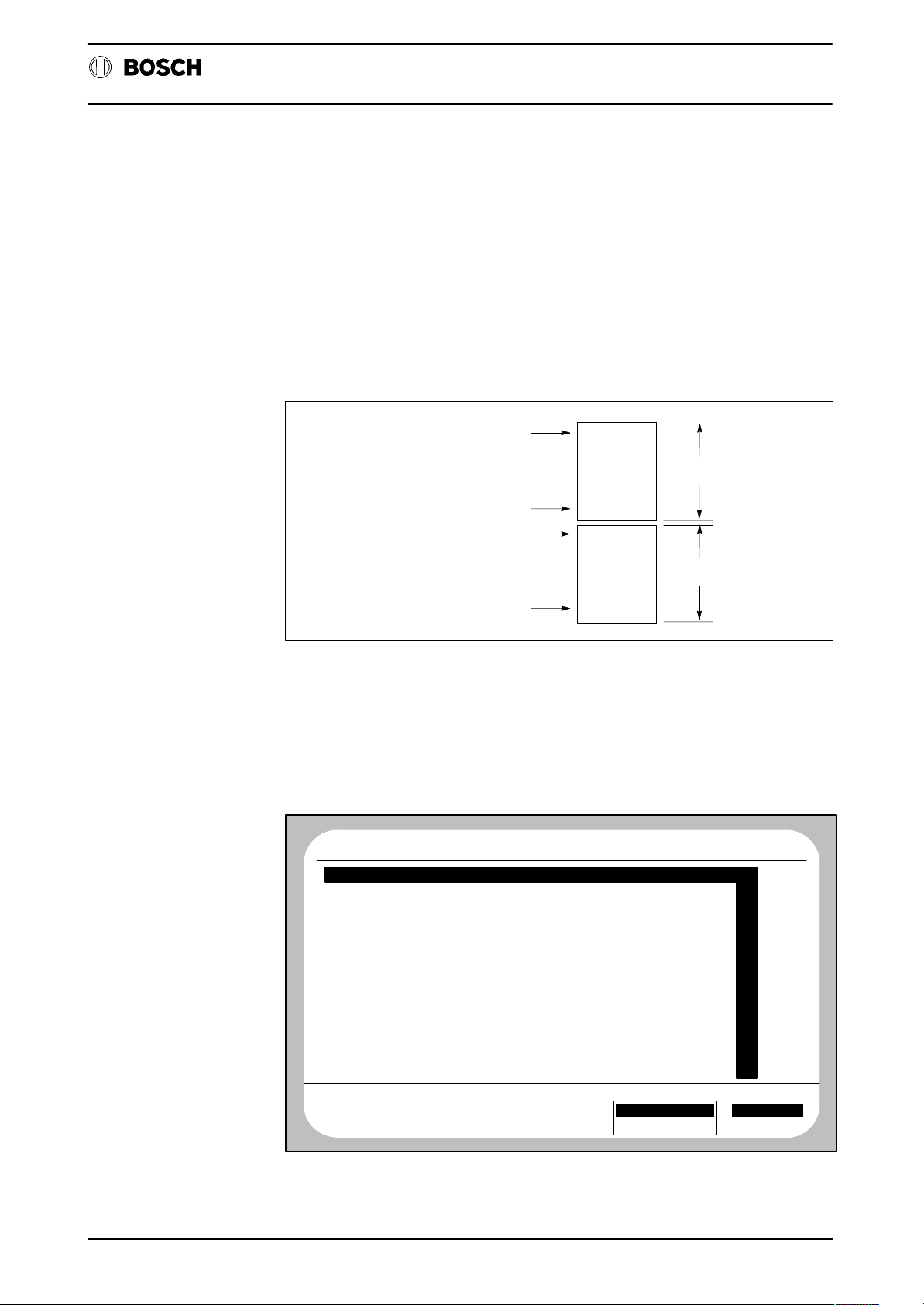
The softkeys DISPLAY X–AXIS and DISPLAY Y–AXIS are used to assign an arbitrary machine axis (axis number) to the abscissa (DISPLAY X–AXIS) and to the ordinate (DISPLAY Y–AXIS) of the contour diagram.
The softkeys Y–AXIS EXP ANSION and X–AXIS EXPANSION should be used only
in conjunction with D27 (circular compensation).
In order to optimize parameters set with D27, it is necessary to expand the representation of one axis involved in circular interpolation more than the other (e.g. X
and Y). This makes it possible to see the contour errors at quadrant transitions of
a circle more easily.
The expansion factor can be entered separately for each axis (value range: 1 –
1000).
In order to avoid a situation where the contour can no longer be completely dis-
played on the monitor as a result of axis expansion, reduction of the non–expanded
axis by the specified factor occurs instead of an increase in the expanded axis. The
displayed proportions are thus correct.
Example:
Y
Y
Y
X
No expansion Y−axis expanded by
a factor of 2
X
X−axis expanded by
a factor of 2
X
Note:
If the function EXPANSION is active for an axis, the text ”AXIS” with the corresponding expansion factor appears on the display under the column ”MAGNIFI.
FACTOR” (refer to softkey DISPLAY) in addition to ”DISPLAY” and ”MAGNIF.”.
D23 – 36
Page 42

Flexible Automation
TRIGGER
D23 Contour display
CC 220 / 320
Diagnosis
MOVE
JOG BUTTON
PROGR. NO.
BLOCK NO.
Definition of trigger condition. When the softkey START RECORDING is pressed,
recording is delayed until the trigger event defined here occurs. The active trigger
condition is indicated by inverted display of the corresponding softkey.
START
RECORDING
After operation of START RECORDING, recording is started when the trigger condition occurs.
The message ”RECORDING” appears under the line ”CONTOUR DISPLAY”. The
status ”WAITING” is displayed here when recording has been completed.
DISPLAY
The contour diagram can be called after the end of a recording by pressing the softkey DISPLAY.
The set and actual contours are shown (set contour: green; actual contour: red).
Two cross–hairs can be moved simultaneously along the contour with the cursor
keys
tion and
. results in cross–hair movement opposite to the machining direc-
in movement in machining direction.
The values for axis position and axis speed (referred to the contour locations
marked by the cross–hairs) are displayed on the left of the monitor.
The ”movement speed” of the cross–hairs can be preselected with the softkey
<<
<
(see next monitor display). The active mode is shown inverted on the softkey:
<< Fast movement (step distance = 10 sampling steps)
< Slow movement (step distance = 1 sampling step).
D23 – 37
Page 43

Flexible Automation
D23 Contour display
CC 220 / 320
Diagnosis
MAGNIFI. FACTOR
DISPLAY
MAGNIF.
CURSOR VALUE
COMMAND−POS.
X 47.883
47.883Y
ACTUAL−POS.
X 48.618
49.110Y
COMMAND−SPEED
X −0.708
−0.708Y
ACTUAL−SPEED
X −0.243
−0.531Y
1.00
Y
X
<<
<
The whole display or part of it can be magnified with the MAGNIFIER key in order
to examine certain contour locations.
A frame appears on the screen after operation of the MAGNIFIER key . In addition,
the following softkey bar is offered:
MAGNIFI. FACTOR
DISPLAY
MAGNIF.
CURSOR VALUE
COMMAND−POS.
X 47.883
47.883Y
ACTUAL−POS.
X 48.618
49.110Y
COMMAND−SPEED
X −0.708
−0.708Y
ACTUAL−SPEED
X −0.243
−0.531Y
1.00
10.00
Y
X
ON OFF + −
ON
<<
<
Magnification of the displayed frame content to the complete display area of the
monitor. The cross–hairs stay in their current position and may thus not be visible
initially after magnification.
OFF
Deactivation of the magnifier function. The graphic display is built up again without
magnification. The cross–hairs stay in their current positions.
D23 – 38
Page 44

Flexible Automation
D23 Contour display
+ –
Magnification or reduction in size of the displayed magnifier frame.
The step distance by which the frame is magnified or reduced each time the soft-
keys ”+” or ”–” are pressed can be set by means of the softkey <<< .
The frame can be moved arbitrarily with the cursor keys while the magnifier frame
is displayed on the monitor.
The step width by which the frame is moved can be adjusted by way of softkey
<<
<
.
Example: Magnified display of the previously marked screen section.
Y
MAGNIFI. FACTOR
DISPLAY
MAGNIF.
CURSOR VALUE
COMMAND−POS.
X 47.883
47.883Y
ACTUAL−POS.
X 48.618
49.110Y
COMMAND−SPEED
X −0.708
−0.708Y
ACTUAL−SPEED
X −0.243
−0.531Y
10.00
10.00
Diagnosis
X
CC 220 / 320
ON OFF + −
<<
<
Note:
‘ It is possible to perform magnification several times successively. However,
when the displayed values under the column ”MAGNIFI. FACTOR” are re-
placed by an asterisk, magnification should be stopped.
D23 – 39
Page 45

Flexible Automation
D23 Contour display
CC 220 / 320
Diagnosis
D23 – 40
Page 46

Flexible Automation
D24 – Axis optimization
General
D24 Axis optimization
The servo loops of the control must be adapted to the drives used. The diagnostic
program D24 offers the following functions for this purpose:
‘ Definition of a step function (speed) for each applied axis.
‘ Graphic representation of the axis reaction to the step function (as speed
characteristic) and numeric display of the determined servo loop parameters.
‘ Display of position, lag, offset and required lag of all axes.
‘ Modification of the active required closed–loop gain.
‘ Offset adjustment of one axis.
‘ Acceptance of the optimized closed–loop gain and offset values in the ma-
chine parameters.
Diagnosis
CC 220 / 320
The axis reaction is always measured by recording of 160 actual axis position values. The time between 2 sampling operations corresponds to the value entered in
machine parameter P9901. The recording time is thus 1.6 s if P9901 = 10 ms.
User interface/softkey assignment
The following monitor display appears after selection of D24:
No CP0
AXIS OPTIMIZATION
WAITING
DISPLAY AXIS:
TIME SCALE (SEC):
TRAVEL RANGE (MM):
TARGET VALUE (M/MIN):
SERVO LOOP WITH SLOPE
ACCELERATE
DISPLAY
ACT
ADJUSTMENTS
STARTING
VALUES
NC0
WAIT
AXIS OPTIMIZATION STATUS
X
0.50
100
1.00
MACHINE
PARAMETER
SELECTION
AXIS
DIAGNOSTIC
20.2 17:2PROGRAM
START
RECORDING
AXIS
SELECTION
Selection of the machine axis which it is wished to optimize by input of the axis number.
D24 – 41
Page 47

Flexible Automation
D24 Axis optimization
STARTING
VALUES
CC 220 / 320
Diagnosis
SERVO O/P
SERVO LOOP
SERVO O/P
SERVO LOOP
DECELERATE/
ACCELERATE
TARGET
VALUE
TRAVEL
RANGE
Selection of the following operating modes is possible by repeated operation of this
softkey:
‘ SERVO LOOP WITH SLOPE: The axis accelerates to the speed en-
tered on the softkey TARGET VALUE
with a slope. The servo loop is closed
during this operation (refer to machine
parameter P1002 for details of slope).
‘ SERVO LOOP WITHOUT SLOPE: The axis accelerates without slope to
the speed entered under the softkey
TARGET VALUE. The servo loop is
closed during this operation (refer to
machine parameter P1002 for details of
slope).
‘ SERVO OUTPUT: The servo loop is open. The axis tra-
verses at the speed which was entered
under the softkey TARGET VALUE.
The measuring system is used only for
speed measurement.
DECELERATE
ACCELERATE
Selection of acceleration or deceleration.
TARGET
VALUE
It is possible to define the desired axis speed in m/min. here. 10 % of the maximum
speed (refer to machine parameter P501) is stored as a default value for the modes
SERVO LOOP with/without SLOPE. The entered value is interpreted in V in
SERVO OUTPUT mode (default value:
1.5 V).
TRAVEL
RANGE
Input of the maximum distance which may be traversed for a single measurement
(corresponds to an incremental value as from the starting position!). If the limit
value entered here should be exceeded during the measurement, the axis will stop
and a corresponding message is displayed.
Please note the maximum traversing range of your machine if you perform
several successive measurements!
D24 – 42
Page 48

Flexible Automation
D24 Axis optimization
MACHINE
PARAMETER
The following display appears:
CC 220 / 320
Diagnosis
No CP0
PROGRAM
POSITION LAG OFFSET REQIRED LAG
X
0.000
Y
0.000
Z
0.000
0.000
OFFSET−ADJ
AUTO
ACT
X
Y
Z
OFFSET−ADJ
MANUAL
0.000
0.000
0.000
0.000
NC0
STOP
X
Y
Z
REQUIRED
0.002
0.000
0.000
0.000
LAG
X
Y
Z
DIAGNOSTIC
2000.000
2000.000
10000.000
10000.000
ACTIVATE
Offset and required lag values of all axes can be changed on this operating level.
Select the axis where you wish to change the values with the cursor keys
.
SERVO
SERVO
OFFSET–ADJ
AUTO
OFFSET–ADJ
MANUAL
Automatic or manual offset adjustment. The lag should set itself to zero when
the offset has been entered or automatically adjusted. The changed offset value
is transferred directly to the axis processor and is thus active. The machine parameter record is not yet changed at this point in time. Active offset values remain active
until they are overwritten by other offset values or until the control is reset.
REQUIRED
LAG
Input of a new required lag value. This input must be made with care in order to
exclude incorrect drive response.
The required lag is calculated as follows:
Required lag = max. axis speed (P501)/required closed loop gain (P1001).
If the required lag is changed by means of this softkey, the new value becomes active for the corresponding axis when the ENTER key is pressed. For this purpose,
the CNC adapts the currently active required closed loop gain in accordance with
the above relationship (the maximum axis speed remains constant).
The entered value remains active until the control is reset or until a different value
is entered.
The CNC modifies machine parameter P1001 correspondingly if the required lag
is changed by means of the softkey REQUIRED LAG and this value then transferred to the machine parameter record (by softkey ACTIVATE). P501 remains
constant. The new values are then active after each control run–up.
D24 – 43
Page 49

Flexible Automation
MP
D24 Axis optimization
ACTIVATE
All currently active closed loop gain and offset values are immediately transferred
to the machine parameter record when the softkey ACTIVATE is pressed. The
READY 2 signal is cancelled and a new control run–up takes place.
Caution:
The new values are not transferred to the file L444, if this file should exist. If you
wish the file L444 to contain the modified values, you must first delete L444 after
transfer and then regenerate it (with/without texts).
Diagnosis
CC 220 / 320
D24 – 44
Page 50

Flexible Automation
MOVE
D24 Axis optimization
START
RECORDING
When this softkey is pressed, the text under AXIS OPTIMIZATION changes from
”WAITING” to ”RECORDING”. The instruction ”ACTIVATE JOG BUTTON” ap-
pears in the message line.
The traversing movement starts after operation of the jog button (also without
approached reference point or active jog mode!)
DISPLAY
The step response of the corresponding axis can be displayed as a graph after
completion of a recording by pressing the softkey DISPLAY:
Diagnosis
CC 220 / 320
ABSOLUTE VALUE
(M/MIN)
XI
1.00
CHARACTERISTIC
DELAY TIME
0.000 S
TU
REACTION TIME
TA 0.136
OVERSHOOT
UE 44.600
CHAR.FREQ.
WO 68.837
DAMPING
DA 0.320
I.S.E.
3.7
KV
8.867
S
X
1/S
XI
T
One scale division of the time axis (T) always corresponds to 50 sampling steps.
Consequently, the corresponding time interval of a scale division is nt = 50*P9901
(the time interval of a scale divisions is also displayed numerically in the start
screen of D24 under the column ADJUSTMENTS as ”TIME SCALE (SEC):”).
One scale division of the absicissa (XI) always corresponds to 10 % of the currently
set target value.
In addition to the graph, the CNC also displays the internally calculated characteristic servo loop values on the left side of the screen:
XI: Currently active target value
TU: Delay time
TA: Reaction time
UE: Overshoot (in % of XI)
WO: Characteristic frequency (characterized by envelope curve A
in following figure)
DA: Damping (characterized by n1/n2 in the following figure)
I.S.E.: Quadratic control area
KV
: Actual closed loop gain factor
act
= measured speed/measured lag (at last sampling step).
KV
act
D24 – 45
Page 51

Flexible Automation
D24 Axis optimization
Notes:
‘ If the CNC cannot calculate characteristic values which are sufficiently accu-
rate, question marks are displayed instead of the numbers.
‘ Range transgression of a calculated number (numeric value is greater than
the display range) is indicated by the CNC by ”*****”.
Interrelationships of the servo loop characteristics:
Diagnosis
CC 220 / 320
D1
V
D2
TU TA
D1 Magnitude of the 1st overshoot
D2 Magnitude of the 2nd overshoot
WP Reversing point
A Envelope curve
Setpoint speed
V
Set
A
V
Set
WP
TU Delay time
TA Reaction time
5%−
limit
t
Optimization instructions
While the setpoint speed should be reached as quickly as possible for pure positioning operations (thus accepting overshoot), a compromise must be reached between fast attainment of the setpoint speed and the minimum possible overshoot
(contour violation by overshoot) in the case of machining operations (tool engaged).
D24 – 46
Page 52

Flexible Automation
D25 – Lead screw error compensation
General
D25 Lead screw error compensation
The lead screw error compensation function permits compensation of the mechanical inaccuracies of drive spindles or rack drives. It is possible to determine and
compensate both linearity errors as well as reversing backlash.
In order to permit compensation, an error curve is recorded for each axis traversing
direction for each machine axis to be compensated. The actual axis position is
measured exactly with an external device for this purpose. The established compensation data is entered in the files L101–L108 using this diagnostic program. After activation of the function (refer to the section ”General information” at the end
of this chapter), the control corrects the corresponding machine positions automatically.
Note:
Diagnosis
CC 220 / 320
The machine parameter P1509 (reversing backlash) is no longer active if the lead
screw error compensation is active.
User interface/softkey assignment
The following display is an example of the display which will appear on the screen
after selection of D25:
No CP0
AXIS LEAD SCREW ERROR POSITION
X
Y
Z
ACT
NC0
WAIT
0 INCREMENTS
INCREMENTS
0
INCREMENTS
0
DIAGNOSTIC
14.10 8:49PROGRAM
5
INCREMENTS
−
2
4
INCREMENTS
INCREMENTS
EDIT DATA IN PRERUN DATA OUT MANAGE
DATA IN DATA OUT
These keys are used to read the compensation files (L101–L108) in or out via the
standard interfaces of the CNC.
Please refer to the operating manual for further information on reading data in/out.
D25 – 47
Page 53

Flexible Automation
D25 Lead screw error compensation
MANAGE
Deletion of the displayed L files.
All compensation files (L101–L108) are deleted (if present) by the softkey DELETE
ALL. Other files are not deleted by this softkey.
Diagnosis
CC 220 / 320
DATA
It is possible to selectively delete individual files by means of the softkey DELETE
and specification of a file number. It is thus possible to delete all displayed files individually.
EDIT
A compensation file can be created or modified by means of EDIT. After pressing
the key EDIT , enter the file number (101–108) and confirm this with the ENTER key.
An L file is permanently assigned to each axis (X, Y, Z etc.). The following applies
in accordance with machine parameter P102: Axis 1: L101; Axis 2: L102...Axis 8:
L108.
After selection of the required file, the control switches to the LSEC editor . All ASCII
characters required for programming of the compensation values are displayed in
the softkey bar:
EDIT L101
LF X S R P N
OTHER
COMMANDS
The ASCII character is inserted at the current cursor position by operation of the
1st or 2nd softkey (from the left). In the case of softkeys which possess 2 characters, first select the character which it is wished to insert by repeatedly pressing this
key (the selected character is shown inverted in the softkey). This character is then
inserted at the current cursor position after operation of the ENTER key.
Notes:
‘ The 2nd softkey is always assigned the axis address valid for this com-
pensation file.
‘ Refer to the section ”Programming compensation values” for the meaning
of the ASCII characters.
‘ All required characters (except for the character LF!) can also be entered on
the ASCII keyboard.
OTHER
COMMANDS
Selection of further editor functions (refer to manual ”Operating instructions”.
D25 – 48
Page 54

Flexible Automation
D25 Lead screw error compensation
PRERUN
When the corresponding L–files have been created for all axes which are to be
compensated, a test run can be started by way of the PRERUN function which
checks the created L–files for errors.
Error–free files are provided with the identifier ”LSEC” instead of the date in the directory display after the test run.
The lead screw error compensation function can be activated by CLEAR ALL
LOGIC only when all compensation files are error–free.
The following error messages can occur during the test run:
LSEC–SYNTAX: Syntax error in the file.
LSEC–LOGIC: The file is not unambiguous.
LSEC–GRID: Entered compensation positions are not on the grid defined by
the step distance.
Diagnosis
CC 220 / 320
LSEC–OVER: Values outside the display range. The following rules apply:
Positions: max. 8 positions
Error values: max. +/– 32 767
A maximum of 4000 compensation values are possible per traversing direction for all axes. This includes grid points which
are not programmed with a compensation value.
Refer to the handbook ”Error messages”, P. No. 3914 for detailed error descrip-
tions.
D25 – 49
Page 55

Flexible Automation
Determination of the error curve
D25 Lead screw error compensation
The position errors must be determined for both the positive and negative traversing directions for each desired axis.
The unit of length for position and compensation values depends on the resolution
used. Normally, the resolution is 1 lm for linear and 1/100 of a degree for circular
axes.
First subdivide the traversing range of an axis into a number of equally large sections (guide value, approx. 10–20 mm). This grid defines the positions in the tra-
versing range at which position compensation values may be programmed later
on (refer to the section ”General information” for maximum number of position com-
pensation values).
Travel the axis to the start of the traversing range (normally position 0) after reference point travel.
Diagnosis
CC 220 / 320
MOVE
Now define the actual axis position using an external measuring device. The difference between the actual and setpoint positions (P
compensation value which must be specified later on for this position.
First perform this measurement in positive traversing direction for arbitrary setpoint
positions located on the grid. When you reach the end of the traversing range, perform measurement in negative traversing direction for arbitrary setpoint positions
on the grid.
A maximum of 4000 compensation values can be entered in the control per traversing direction for all axes together.
Pos. traversing direction
Complete traversing range
Measuring positions; the measuring position distribution may be
=
non−uniform over the complete traversing range. The measuring
positions themselves must, however, all be located on the grid.
– P
act
Neg. traversing direction
) corresponds to the
set
Note:
It is not necessary to measure all positions defined by the grid in one traversing direction. If several grid points which are not measured lie between 2 positions in a
traversing direction, the compensation value of the last–measured point applies to
these grid points (also refer to the section ”General information” at the end of this
chapter). In this way, it is possible to perform compensation only in specific, particularly critical areas of the traversing path of an axis.
D25 – 50
Page 56

Flexible Automation
Programming the compensation values
D25 Lead screw error compensation
Several characters are used as well as numbers for programming a compensation
file. By means of these characters, the control recognizes the meaning of any numeric value which has been programmed after them.
Note:
All characters required are offered on the softkey level EDIT, but can also be entered on the ASCII keyboard. Exception: The character LF must be entered by way
of the softkey LF on the softkey level EDIT.
All numeric values must be programmed as integers in the unit of the positioning
resolution (minimum traversable distance). The positioning resolution depends on
machine parameter P103:
Diagnosis
CC 220 / 320
Positioning resolution:
(increment length)
Examples: Axis type P103 Positioning resolution
Linear 3 1 m
Linear 2 10 m
Circular 3 1/1000th degree
Circular 2 1/100th degree
Characters used for programming:
<LF>: (LINE FEED). Each programmed line of a compensation file
S: Step distance of the grid. The step distance must be pro-
P103
110
must be terminated with <LF>.
grammed in the first line of the compensation file.
The reference point and all axis position values programmed later on must lie on this grid. However, it is not
necessary to assign a compensation value to each grid
point.
Examples:
Linear axes:
”S20000” means: compensation values may be programmed every 20 mm (with 1 m positioning resolution).
Circular axes:
”S1000” means: compensation values may be programmed every 10 degrees (with 1/100th degree positioning resolution).
<AXIS ADDRESS>: (e.g. ”X”, ”Y”, ”Z”). The position of the compensation value
is programmed by the axis address with subsequent numeric value. The compensation value itself (refer to character ”P or N”) must be programmed in the same line as the
position value.
D25 – 51
Page 57

Flexible Automation
D25 Lead screw error compensation
R: This identifies the following number as the position of the
reference point. The compensation value itself (refer to
characters ”P, N”) must be programmed in the same line as
the reference point position.
Examples:
Linear axis:
”R100000” means: reference point position at 100 mm
(with 1 m positioning resolution).
Circular axis:
”R35000” means: reference point position at 350 degrees
(with 1/100th degree positioning resolution).
P, N: ”P” identifies the following number as a compensation value
in positive traversing direction. ”N” identifies the following
number as a compensation value in negative traversing direction. The compensation value to be entered corresponds to the difference between the actually measured
position and setpoint position in the unit of positioning resolution.
Diagnosis
CC 220 / 320
Examples:
Setpoint position Actual position Compensation value
10000 10002 2
10000 9998 –2
10000 10000 0
Programming for circular axes
Only compensation values for the position range 0° x X t 360° need be pro-
grammed for circular or infinite axes.
If a circular axis moves out of this range, a modulo calculation is performed with
respect to the axis position for access to the compensation values so that the compensation values for the position range 0° x X t 360° are active.
Examples:
An initial position of 300° and an end position of 400° are defined, for example,
when programming a circular axis in the part program. The compensation values
programmed for the traversing range from 300° to < 360° are used for this range,
while the compensation values programmed for the range 0° to 40° are used for
the traversing range from 360° to 400°.
The same is true analogously, for example, for a traversing distance from +40° to
–40°. The compensation values programmed for the range from < 360° to 320° are
active for the path from –0° to –40°.
D25 – 52
Page 58

Flexible Automation
D25 Lead screw error compensation
Diagnosis
Programming example:
The traversing range of the X–axis (0–100 mm) has been subdivided into a grid with
a step distance of 10 mm. Let the reference point position of the X–axis in this example be X = 100 [mm].
Error
[m]
8
6
4
CC 220 / 320
2
−2
−4
−6
−8
10 20 30 40 50
60
70
Compensation characteristic of the X−axis
90 100 110
80
Setpoint position
103]
[m
*
: Measuring points
: Compensation char.
in positive direction
: Compensation char.
in negative position
Programming:
The file L101 must be programmed for the compensation values of the X–axis.
S10000<LF> Step distance 10000 l; compensation value input
possible every 10 mm.
X0P0<LF> No compensation in pos. travel direction at X0
X10000P2<LF> Compensation by +2 l in pos. travel direction at X10
X30000P2<LF> Compensation by +2 l in pos. travel direction at X30
X40000P4<LF> Compensation by +4 l in pos. travel direction at X40
X60000P1<LF> Compensation by +1 l in pos. travel direction at X60
X70000P–4<LF> Compensation by –4 l in pos. travel direction at X70
X80000P–2<LF> Compensation by –2 l in pos. travel direction at X80
X90000P0<LF> No compensation in pos. travel direction at X90
R100000P0<LF> No compensation in pos. travel direction at X100
(reference point)
R100000N0<LF> No compensation in neg. travel direction (reversal point)
at X100 (reference point)
X90000N0<LF> No compensation in neg. travel direction at X90
X80000N–2<LF> Compensation by –2 l in neg. travel direction at X80
X50000N6<LF> Compensation by +6 l in neg. travel direction at X50
X20000N3<LF> Compensation by +3 l in neg. travel direction at X20
X10000N2<LF> Compensation by +2 l in neg. travel direction at X10
X0N0<LF> No compensation in neg. travel direction at X0
M30 File end
D25 – 53
Page 59

Flexible Automation
General information
D25 Lead screw error compensation
‘ If there are several grid points which have not been programmed between
two programmed grid points in a traversing direction, the compensation
value of the last–programmed grid point applies to these grid points which
have not been programmed. Compensation values for machine positions
between two successive group points are calculated by the control by way
of linear interpolation.
‘ Error compensation starts to act at the first programmed position in a com-
pensation file.
Error compensation ends at the last programmed position in a compensation file.
‘ A maximum of 4000 compensation values are possible per traversing direc-
tion for all axes. The grid points which have not been ”filled out” are included
in this total.
‘ The position values for the positive traversing direction must be pro-
grammed in ascending order and those for the negative traversing direction
in descending order.
Diagnosis
CC 220 / 320
‘ Position information for circular axis compensation values must lie in the
range 0° x X t 360°.
‘ The reference point must lie on the compensation grid; a compensation
value can be entered here as well.
D25 – 54
Page 60

Flexible Automation
D26 – Remote diagnosis (information)
D26 CNC remote diagnosis (information)
Fast and extensive information about failed installations is essential in order to satisfy the availability demands placed nowadays on modern machine concepts. For
this purpose, BOSCH offers the user the ”remote diagnosis” option, which allows
the service center to be informed by telephone about the type and scope of the
problems which have occurred at short notice.
For this purpose, the service or maintenance center possesses a remote diagnosis
computer, a fully–configured CNC control equipped with special software. The option ”remote diagnosis” must be applied to the machine (at the
machine tool manufacturer or end customer) for the CNC to be diagnosed and REMOTE DIAGNOSIS (softkey) activated. D26 is activated directly by the remote
diagnosis computer only for certain diagnostic functions such as local analyzer,
axis oscilloscope, MSD etc. D26 automatically deactivates itself after completion
of these functions.
Information is exchanged between the CNC and service center on a telephone line
using an acoustic coupler or modem. The signalling rate can be set to 300, 1200,
2400 or 4800 baud by means of machine parameter 5509.
CC 220 / 320
Diagnosis
When a connection has been established between the two controls, the service
center is in a p o s i tion to inform itself about the following data of the connected CNC:
Error messages
All pending error messages (from control and machine) are transmitted to the service center immediately after they occur and are displayed on the CNC.
DIAGNOSTIC mode, softkey CONTROL
The service center can receive information about the software version on this operating level.
DIAGNOSTIC mode, softkey MACHINE
Transmission of the current MSD data (machine status display) and the input and
output states present at the PLC at the time of transmission.
Messages
The service center can output any message in plain text on the monitor of the connected CNC if it is wished to exchange all information (e.g. ”Please remove receiver
from acoustic coupler”).
DIAGNOSTIC mode, softkey SERVICE FUNCTION
‘ Axis oscilloscope: Recording of axis data with subsequent transmission of
the values to the service center for evaluation.
‘ Logic analyzer: Signal and trigger settings; after the end of recording, the re-
corded data can be transmitted to the service center.
File transfer
The following files can be transferred:
Part programs (file group P), diagnostic programs (file group D), graphic programs
(file group G), system data (file group L), offset tables (file group V), compensation
tables (file group K) and W–tables (file group W).
D26 – 55
Page 61

Flexible Automation
D26 CNC remote diagnosis (information)
Directory display
The service center can have displayed all or specially selected directories
of the individual file groups.
File transfer CNC ––> remote diagnosis computer
After a certain file has been selected, this can be transmitted by the control
to the remote diagnosis computer and evaluated there.
File transfer remote diagnosis computer ––> CNC
Any files can be transmitted to the user by the remote diagnosis computer
(e.g. after correction of a part program at the service center).
File deletion
Individual files can be deleted from the service center.
CC 220 / 320
Diagnosis
D26 – 56
Page 62

Flexible Automation
D27 – Putting into operation for circular compensation
General
D27 Putting into operation
for circular compensation
The diagnostic program acts as an aid for putting into operation the option CIRCULAR COMPENSATION.
Other required commissioning aids: – D23 Contour display.
You will find further information on the option CIRCULAR COMPENSATION in the
section ”Circular compensation”.
Please refer to the sections ”Preparations for optimization” and ”Optimizing the circular compensation parameters” for preparations and procedure for optimization.
Notes:
CC 220 / 320
Diagnosis
‘ The option requires the servo loop board SERVO–i and the option CS–
TABLES.
‘ Circular compensation is possible only for synchronous linear axes and is
sensible only in conjunction with a direct measuring system.
‘ If the option PILOT CONTROL is activated in the system, the pilot control
weighting factors (machine parameters P1016 and P1017) must have been
optimized to minimize lag before circular compensation is activated and optimized.
Circular compensation
The option CIRCULAR COMPENSATION allows contour errors to be minimized
during circular interpolation in the area of the quadrant transitions (at the reversal
point of an axis).
These contour errors occur with different degrees of severity on individual machines owing to the respective mechanical design (static friction, torsion etc.).
D27 – 57
Page 63

Flexible Automation
D27 Putting into operation
for circular compensation
CC 220 / 320
Diagnosis
Circle contour display in diagnostic
program D23 and assignment of the
reversal points to the axes
Y
Uy1
Ux1Ux2
Uy2
X
U
1 = 1st reversal point X−axis
x
2 = 2nd reversal point X−axis
U
x
U
1 = 1st reversal point Y−axis
y
Uy2 = 2nd reversal point Y−axis
Speed characteristic of both
axes involved in circular interpolation
V
x
Ux1
Ux2
V
y
Uy1
Uy2
V
y
Uy1
t
Magnified
representation of
the point U
y
t
t
1
In order to avoid contour errors, a compensation pulse is generated at the reversal
point of the respective axis in addition to the setpoint input. This ensures continuous movement of this axis through the standstill point (breakaway from static friction at the right time).
The ideal pulse height is related non–linearly to the path velocity. When the option
is put into operation, this non–linear function must first be determined and graphically plotted for the reversal points of all axes involved in circular interpolation on
the basis of measurements (with D27 and D23). This function is then approximated
by a maximum of three adjacent straight lines, thus providing a maximum of four
reference points (SP1–SP4) with the parameter pairs of pulse height (PH) and path
velocity (VB) (refer to following figure).
P
H
SP1
Measured values=
SP = Reference points
SP2
SP3
SP4
V1 V2 V3 V4
Measured curve and its approximation by 3 straight lines
D27 – 58
V
B
Page 64

Flexible Automation
D27 Putting into operation
for circular compensation
The W–table W999999003 is used for recording all parameters necessary for circular compensation (refer to the section ”Preparations for optimization” for the W–
table definition program). The content of this table is read during every control
run–up and is then active until a renewed run–up operation.
On the basis of these values, the CNC calculates the required pulse height by linear
interpolation for arbitrary speeds.
The pulse height is decreased linearly down to P
first programmed reference point (SP1) down to the speed V
remains constant for path velocities above the last programmed reference point
(SP4).
= 0 for path velocities below the
H
CC 220 / 320
Diagnosis
= 0. The pulse height
B
D27 – 59
Page 65

Flexible Automation
User interface/softkey assignments
D27 Putting into operation
for circular compensation
The following monitor display appears after D27 has been started:
CC 220 / 320
Diagnosis
No CP0
AXIS:
COMPENSATION PULSE 1.Q:
COMPENSATION PULSE 2.Q:
COMPENSATION TIME: 20
AXIS
NUMBER
AXIS
NUMBER
ACT
ADJUSTMENTS
COMPENSATION
PULSE 1.Q
NC0
STOP
CIRCULAR COMPENSATION
1
0
0
COMPENSATION
PULSE 2.Q
COMPENSATION
TIME
Selection of the axis to be optimized (value range: 0–8).
COMPENSATION PULSE
1.Q
COMPENSATION PULSE
2.Q
DIAGNOSTIC
30.11. 14: 8PROGRAM
ACTIVATE
SERVO
Input of the compensation pulse height at the 1st and 2nd reversal points respectively of the selected axis in the unit lm (value range: 0 – 9999).
COMPENSA-
TION TIME
Input of the compensation pulse duration in interpolation steps (value range: 0 –
9999). The actual pulse duration is calculated as follows: T = input value *P9901.
The parameter ”Compensation time” is preassigned the value 20 and should not
normally be changed.
ACTIVATE
The values displayed under ”ADJUSTMENTS” are transferred directly to the interpolation processor for optimization when this softkey is pressed. Transfer o f the values to the W–table does not take place automatically.
Caution:
‘ The optimized circular compensation parameters have to be manually en-
tered in the W–table W 999999003 (refer to the section ”Preparations for optimization” for definition and structure of the W–table).
This W–table is evaluated during every control run–up (if the option CIR-
CULAR COMPENSATION is applied).
D27 – 60
Page 66

Flexible Automation
Preparations for optimization
D27 Putting into operation
for circular compensation
‘ The values become active only if all parameters of the corresponding axis
have been preassigned the value ”0” in the W–table before the last control
run–up or if W 999999003 does not exist.
Several preparations have to be made before optimization:
‘ Test program generation
Example: P110 N10 G0 X50 Y60 Z0
N20 G17 G2 X60 Y50 R40
N30 G0 X50 Y60
M30
Since circular compensation is active only during circular interpolation and not at
its start/end, the start and end points must not be programmed at a quadrant transition in this test program.
‘ Generation of a definition program for W–table W999999003
CC 220 / 320
Diagnosis
(DFS, W999999003,COMPENSATION–TAB)
$[8]
$[A,W,40,0,COMPENSATION TIME]
$[B,W,40,0,U1:.1.F–VALUE.]
$[C,W,40,0,U1:.1.P–HEIGHT]
$[D,W,40,0,U1:.2.F–VALUE.]
$[E,W,40,0,U1:.2.P–HEIGHT]
$[F,W,40,0,U1:.3.F–VALUE.]
$[G,W,40,0,U1:.3.P–HEIGHT]
$[H,W,40,0,U1:.4.F–VALUE.]
$[I,W,40,0,U1:.4.P–HEIGHT]
$[J,W,40,0,U2:.1.F–VALUE.]
$[K,W,40,0,U2:.1.P–HEIGHT]
$[L,W,40,0,U2:.2.F–VALUE.]
$[M,W,40,0,U2:.2.P–HEIGHT]
$[N,W,40,0,U2:.3.F–VALUE.]
$[O,W,40,0,U2:.3.P–HEIGHT]
$[P,W,40,0,U2:.4.F–VALUE.]
$[Q,W,40,0,U2:.4.P–HEIGHT]
$[@1,8,AXIS NUMBER]
#*
M30
Store the definition program on a data medium (Important: read out without DFS
identifier!).
The W–table is generated later on by reading this definition program into the con-
trol.
The table contains 8 columns (axis number 1–8) of 17 lines each (circle parameters). The compensation time required for the respective axis will be entered later
under address ”A”.
A maximum of 4 parameter pairs (pulse height and path velocity) can be specified
under addresses B to I for the first reversal point (U1). The parameter pairs for the
second reversal point (U2) should be entered in addresses J to Q.
The addresses of the parameter pairs valid for a reversal point need not be com-
D27 – 61
Page 67

Flexible Automation
Optimizing the circular compensation parameters
D27 Putting into operation
for circular compensation
pletely allocated in the W–table. It is thus also permitted, for example, to specify
only two parameter pairs.
D27 allows you to preallocate corresponding compensation values for the two reversal points of each axis.
Please note that the entered values are active only if the W–table values of the corresponding axis have been preallocated the value ”0” and are active or if
W999999003 does not exist (also refer to the section ”User interface/software as-
signments” under softkey ACTIVATE).
Diagnostic program D23 can be used to check the contour after execution of a
circle.
For this purpose, setpoint and actual contours are displayed in D23. In order to permit the quadrant transition to be seen more easily, the respective axis can be expanded on the display (for instructions on operation of D23, refer to chapter ”D23
Contour display”, softkey EXPANSION.
1. Define the radius which is to be used for optimization. Define the speed
range within which optimization is to take place. 9999 mm/min. is the maximum permitted path feedrate.
CC 220 / 320
Diagnosis
MOVE
SERVO
MOVE
2. Adapt the test program P110 (feedrate, radius) and then perform program
selection.
3. Select D23 and set the trigger condition (e.g. program number = 110, block
number = 20).
4. Start D23 recording. Start test program.
5. Check quadrant transitions with contour display.
6. Select D27. Enter the corresponding axis number and compensation values
(compensation pulse 1.Q/2.Q). Then press softkey ACTIVATE.
7. Select D23. Start recording. Start test program.
8. Check the quadrant positions. Optimize the compensation values if the com-
pensation is too large or too small (repeat steps 6–8).
9. Determine the optimum compensation values for various speeds by adapt-
ing the test program (feedrate). Note the found compensation values in a
table (feedrate value, compensation path).
Plot noted values graphically for each reversal point. Perform further measurements if necessary at critical points.
10. Approximate measured curves by maximum of 3 straight lines (refer to sec-
tion ”Circular compensation”).
11. Generate W–table and plot parameter pairs of the reference points.
12. Transfer the W–table values by pressing the softkeys RESET FUNCTION
and CLEAR ALL LOGIC in group operating mode DIAGNOSTIC.
D27 – 62
Page 68

Flexible Automation
D28 – Tapping without compensation chuck
General
User interface/softkey assignments
D28 Tapping
CC 220 / 320
Diagnosis
The diagnostic program D28 acts as a commissioning aid for the option ”TAPPING
WITHOUT COMPENSATION CHUCK” for correct adjustment of the pilot control
weighting factors for speed and acceleration (machine parameters P7203 and
P7204).
Note:
The option requires the servo loop board SERVO i.
The following display appears after D28 is started:
No CP0
RECORDING
WAITING
AXIS:
V−WEIGHTING:
A−WEIGHTING:
Y1 :
Y2 :
X−EXPANSION:
X−EXP. START:
JOG BUT TON 1. AXIS
DISPLAY
ACT
ADJUSTMENTS
1000
1000
100
TRIGGER SETTING
NC0
STOP
1
0
0
MM/MIN
MM/MIN
MS
0 SCALE DIVISION
AXIS
DATA
PER SCALE DIVISION
PER SCALE DIVISION
PER SCALE DIVISION
DISPLAY
SPLITTING
TAPPING
OTHER
COMMANDS
DIAGNOSTIC
30.11. 14: 8PROGRAM
START
RECORDING
DISPLAY
After the end of a recording (refer to softkey START RECORDING), you can have
recorded feedrate and lag values displayed as diagrams on the monitor by pressing
this softkey . The graphic display parameters are influenced by means of the functions offered by the softkey DISPLAY SPLITTING.
D28 – 63
Page 69

Flexible Automation
AXIS
DATA
D28 Tapping
CC 220 / 320
Diagnosis
SERVO
MP
AXIS
NUMBER
FEED
WEIGHTING
ACCELERA-
TION
WEIGHTING
ACTIVATE
On this softkey level, the axis to be optimized and the setpoints of the pilot control
values for feedrate and acceleration can be defined for an optimization step (refer
to the section ”Optimizing the pilot control weighting factors” for the optimization
procedure).
In addition, it is possible to transfer the pilot control values to the machine parameters 7203 and 7204 after optimization by means of the softkey ACTIV ATE, without
the option ”PILOT SPEED CONTROL” having to be activated in the system. A CNC
reset automatically takes place after operation of the softkey ACTIVATE.
Caution:
The values are entered only in the machine parameter record by operation of the
softkey ACTIVATE. The file L444 is not modified.
In order to keep L444 up to date, L444 must first be deleted after transfer and then
regenerated (with/without text) if necessary. Possibly save the machine parameter
record in the EEPROM!
Note:
If it is wished to optimize several axes, it is not necessary to press the softkey ACTIVATE after adjustment of an individual axis. First optimize all desired axes successively and then press the softkey ACTIVATE.
SOFTKEY
DISPLAY
SPLITTING
X–DISPLAY
START
EXPAND X
* 10
SCALE
Y1–AXIS
SCALE
Y2–AXIS
It is possible to manipulate the display parameters of the graphic display here (refer
to softkey DISPLAY).
Both the right start point of the X–axis and expansion of the X–axis by a factor 10
as well as scale factors for the Y–axes of the feedrate (Y1) and lag diagram (Y2)
can be defined separately.
D28 – 64
Page 70

Flexible Automation
OTHER
COMMANDS
D28 Tapping
CC 220 / 320
Diagnosis
MOVE
TRIGGER JOG
BUTTON
TRIGGER
PROG./BLOCK
After activation of recording (refer to softkey START RECORDING), the start of
data recording is delayed until a specific trigger event occurs.
Both operation of a jog button and the start of execution of a specific program block
can be defined as a trigger event. The set trigger condition is identified by inverse
display of the corresponding softkey.
START
RECORDING
Data recording is activated after operation of this softkey. At this point in time, the
pilot control values entered on softkey level AXIS DATA are valid and not the machine parameter values.
Recording starts when the trigger event occurs in accordance with the set trigger
condition.
During recording, the text ”RUNNING” is displayed on the monitor instead of the
text ”WAITING” (under the line ”RECORDING”).
480 feedrate and lag values are always recorded. The recording time is calculated
as follows:
T[ms] = 480 * P9901.
The generated diagram can be called by means of the softkey DISPLAY only after
the end of recording.
D28 – 65
Page 71

Flexible Automation
Preparations for optimization
D28 Tapping
Several preparations must be made before optimization:
‘ Adaption of the PLC program
The CNC output signal 16.5 is output for the duration of tapping. Feed enable
is permitted by means of this signal although no M3, M4 is output.
‘ Adjustment of machine parameters
P7201 (gear speed–dependent spindle closed–loop gain):
First take over the closed–loop gain value for the spindle axis from machine
parameter P7014.
The closed–loop gain must be set for each gear speed so that no spindle
oscillations occur at the maximum speed which is to be used for tapping.
CC 220 / 320
Diagnosis
P7202 Gear speed–dependent spindle acceleration:
Take over the value from machine parameter P7015.
P7203 and P7204 (axis–specific pilot control weighting factors):
First leave these values unchanged. The values determined later on during
optimization can be transferred here directly from D28 by means of the softkey ACTIVATE.
If the option ”PILOT CONTROL” is applied, it is additionally necessary to
take into account the settings of P1014 and P1015 for optimization. Both pa rameters define the maximum possible limit values for speed and acceleration pilot control weighting factors.
‘ Test program generation
Example:P111 N10 G1 X0 Y0 Z0 M19 S0
N20 G32 F1000 M3 S1000 Z30
N30 G32 F1000 M4 S1000 Z0
M30
Before the start of tapping, the position servo loop of the spindle must be
closed. This is achieved, for example, by way of the function SPINDLE ORIENTATION or SPINDLE STOP (M5).
If drilling is to take place several times in a hole, the spindle must be positioned with M19 before G32 (e.g. subsequent cutting after tool breakage).
D28 – 66
Page 72

Flexible Automation
Optimizing the pilot control weighting factors
D28 Tapping
Aim of optimization: The lag of the drilling axis should be ”0” if possible during tapping. Realistic values here are a lag of less than 10 lm during constant speed
phases and lag values of less than 20 lm during acceleration phases.
The procedure for setting the pilot control parameters is described below.
Since the magnitude of the remaining lag significantly effects the accuracy
of the thread, careful adjustment of the pilot control parameters is essential.
1. Select D28.
2. Set the trigger condition (e.g. program number = 11, block number = 20).
3. Set the axis number (e.g. axis number = 3; Z–axis).
4. Start recording by means of the softkey ST ART RECORDING then start test
program (P111).
CC 220 / 320
Diagnosis
MOVE
SERVO
MOVE
SERVO
5. Evaluate recording. Calculate the active closed–loop gain from the recorded
feedrate and lag values.
6. Compare the active closed–loop gain (CLG
chine parameter P1001. Depending on the result, you can now enter the
rough value of the feedrate weighting factor in D28 under softkey level AXIS
DATA:
Result of comparison Feedrate weighting factor to be entered
CLGact ~ P1001 approx. 10000 ( 300)
CLGact > P1001 significantly less than 10000
CLGact < P1001 greater than 10000
7. Start recording by means of the softkey START RECORDING. Then start
test program (P111).
8. Evaluate recording. The lag which occurred during unaccelerated travel is
now relevant (stationary lag).
Lag Entered feedrate weighting factor
) with the value entered in ma-
act
became less increase; repeat as from step 7.
has changed sign reduce; repeat as from step 7.
(over–compensation)
no reduction OK; continue with step 9.
possible without sign change
Note:
It is possible to increase the resolution of the lag diagram in Y–direction by scale
switchover on the softkey level DISPLAY SPLITTING in order to permit easy recognition of small lag values.
D28 – 67
Page 73

Flexible Automation
SERVO
MOVE
D28 Tapping
9. Increase the value of the acceleration weighting factor in D28 on the softkey
level AXIS DA TA in order to now minimize the lag during acceleration/deceleration (recommendation: step distance 100).
10. Start recording by means of the softkey START RECORDING. Then start
test program (P111).
11. Evaluate recording.
The lag which occurred during accelerated travel is now relevant.
CC 220 / 320
Diagnosis
SERVO
MP
Lag Entered acceleration weighting factor
became less increase; repeat as from step 10.
changed sign reduce; repeat as from step 10.
no reduction OK; continue with step 12.
possible without
sign change
Notes:
It is possible to increase the resolution of the lag diagram in Y–direction by switch-
ing the scale on softkey level DISPLAY SPLITTING in order to permit easy recognition of small lag values.
The lag during an accelerated travel must not change.
12. Select the next axis to be optimized on softkey level AXIS DA TA and adapt
test program (P111). Then continue with step 4.
When the weighting factors have been set for all drilling axes, press the softkey ACTIVATE on softkey level AXIS DATA. This transfers all optimized pilot control
weighting factors to the machine parameter record. The file L444 is not changed
as a result. A CNC reset automatically takes place after this.
In order to keep L444 up to date, you must first delete L444 after transfer and then
regenerate it (with/without text) again if necessary.
13. Check the optimized settings using the diagnostic program D23 CONTOUR
DISPLAY:
The offset between spindle and drilling axis at the reversal point can be determined with D23. To do this, plot the spindle axis and drilling axis against
each other (by means of the softkeys DISPLAY X/Y AXIS on the softkey level
STARTING VALUES). In the ideal case, the ”ACTUAL CONTOUR” pro-
duces a straight line for drilling in and out.
D28 – 68
Page 74

1070 073 306-101 (91.10) GB · HB NC · AT/VSP · Printed in Germany
 Loading...