

Page 1

Typ1 osa / CC 220
CPL Programming Instructions
Version
102
Page 2

Typ1 osa / CC 220
CPL Programming Instructions
1070 073 642-102 (93.06) GB
/Z25 QJ, D25 XA)
E 1993
by Robert Bosch GmbH,
All rights reserved, including applications for protective rights.
Reproduction or handing over to third parties are subject to our written permission.
Discretionary charge 20.– DM
Page 3

Page 4

Flexible Automation
Contents
1. Introduction
Notes and Tips 1 − 1. . . . . . . . . . . . . . . . . . . . . . . . . . . . . . . . . . . . . . . . . . . . . . . . . . . . . . . . . . . . . . . . . . . .
2. Basic elements of CPL
Program structure 2 − 1. . . . . . . . . . . . . . . . . . . . . . . . . . . . . . . . . . . . . . . . . . . . . . . . . . . . . . . . . . . . . . . .
NC block 2 − 2. . . . . . . . . . . . . . . . . . . . . . . . . . . . . . . . . . . . . . . . . . . . . . . . . . . . . . . . . . . . . . . . . . . . . . . . . .
CPL block 2 − 3. . . . . . . . . . . . . . . . . . . . . . . . . . . . . . . . . . . . . . . . . . . . . . . . . . . . . . . . . . . . . . . . . . . . . . . . .
Program start 2 − 4. . . . . . . . . . . . . . . . . . . . . . . . . . . . . . . . . . . . . . . . . . . . . . . . . . . . . . . . . . . . . . . . . . . . . .
Linking 2 − 4. . . . . . . . . . . . . . . . . . . . . . . . . . . . . . . . . . . . . . . . . . . . . . . . . . . . . . . . . . . . . . . . . . . . . . . . . . . .
Parallel processing 2 − 4. . . . . . . . . . . . . . . . . . . . . . . . . . . . . . . . . . . . . . . . . . . . . . . . . . . . . . . . . . . . . . . . .
Autostart 2 − 4. . . . . . . . . . . . . . . . . . . . . . . . . . . . . . . . . . . . . . . . . . . . . . . . . . . . . . . . . . . . . . . . . . . . . . . . . .
Clamp mode 2 − 4. . . . . . . . . . . . . . . . . . . . . . . . . . . . . . . . . . . . . . . . . . . . . . . . . . . . . . . . . . . . . . . . . . . . . . .
Symbolic names 2 − 5. . . . . . . . . . . . . . . . . . . . . . . . . . . . . . . . . . . . . . . . . . . . . . . . . . . . . . . . . . . . . . . . . . .
Reserved instruction words 2 − 5. . . . . . . . . . . . . . . . . . . . . . . . . . . . . . . . . . . . . . . . . . . . . . . . . . . . . . . . . .
Constants 2 − 6. . . . . . . . . . . . . . . . . . . . . . . . . . . . . . . . . . . . . . . . . . . . . . . . . . . . . . . . . . . . . . . . . . . . . . . . .
Integer constant (INTEGER) 2 − 6. . . . . . . . . . . . . . . . . . . . . . . . . . . . . . . . . . . . . . . . . . . . . . . . . . . . . . . . .
Floating−point constant (REAL) 2 − 6. . . . . . . . . . . . . . . . . . . . . . . . . . . . . . . . . . . . . . . . . . . . . . . . . . . . . .
Double−precision constant and double−precision operations 2 − 7. . . . . . . . . . . . . . . . . . . . . . . . . . .
Character string constant (STRING) 2 − 8. . . . . . . . . . . . . . . . . . . . . . . . . . . . . . . . . . . . . . . . . . . . . . . . . . .
Variables 2 − 8. . . . . . . . . . . . . . . . . . . . . . . . . . . . . . . . . . . . . . . . . . . . . . . . . . . . . . . . . . . . . . . . . . . . . . . . . .
Integer variable (INTEGER) 2 − 10. . . . . . . . . . . . . . . . . . . . . . . . . . . . . . . . . . . . . . . . . . . . . . . . . . . . . . . . .
Floating−point variable (REAL) 2 − 10. . . . . . . . . . . . . . . . . . . . . . . . . . . . . . . . . . . . . . . . . . . . . . . . . . . . .
Logic variable (BOOLEAN) 2 − 10. . . . . . . . . . . . . . . . . . . . . . . . . . . . . . . . . . . . . . . . . . . . . . . . . . . . . . . . .
Character string variable (STRING) 2 − 11. . . . . . . . . . . . . . . . . . . . . . . . . . . . . . . . . . . . . . . . . . . . . . . . . .
Array variable (ARRAY) 2 − 11. . . . . . . . . . . . . . . . . . . . . . . . . . . . . . . . . . . . . . . . . . . . . . . . . . . . . . . . . . . . .
DIM 2 − 12. . . . . . . . . . . . . . . . . . . . . . . . . . . . . . . . . . . . . . . . . . . . . . . . . . . . . . . . . . . . . . . . . . . . . . . . . . .
Overview of variables 2 − 12. . . . . . . . . . . . . . . . . . . . . . . . . . . . . . . . . . . . . . . . . . . . . . . . . . . . . . . . . . . . . .
Instructions 2 − 12. . . . . . . . . . . . . . . . . . . . . . . . . . . . . . . . . . . . . . . . . . . . . . . . . . . . . . . . . . . . . . . . . . . . . . .
NUL 2 − 13. . . . . . . . . . . . . . . . . . . . . . . . . . . . . . . . . . . . . . . . . . . . . . . . . . . . . . . . . . . . . . . . . . . . . . . . . .
Mathematical operations 2 − 13. . . . . . . . . . . . . . . . . . . . . . . . . . . . . . . . . . . . . . . . . . . . . . . . . . . . . . . . . . .
SQRT 2 − 14. . . . . . . . . . . . . . . . . . . . . . . . . . . . . . . . . . . . . . . . . . . . . . . . . . . . . . . . . . . . . . . . . . . . . . . . .
ABS 2 − 14. . . . . . . . . . . . . . . . . . . . . . . . . . . . . . . . . . . . . . . . . . . . . . . . . . . . . . . . . . . . . . . . . . . . . . . . . .
ROUND 2 − 14. . . . . . . . . . . . . . . . . . . . . . . . . . . . . . . . . . . . . . . . . . . . . . . . . . . . . . . . . . . . . . . . . . . . . . .
INT 2 − 14. . . . . . . . . . . . . . . . . . . . . . . . . . . . . . . . . . . . . . . . . . . . . . . . . . . . . . . . . . . . . . . . . . . . . . . . . . .
SIN, COS, TAN, ASIN, ACOS, ATAN 2 − 14. . . . . . . . . . . . . . . . . . . . . . . . . . . . . . . . . . . . . . . . . . . . . . .
Logic operations 2 − 15. . . . . . . . . . . . . . . . . . . . . . . . . . . . . . . . . . . . . . . . . . . . . . . . . . . . . . . . . . . . . . . . . .
NOT, AND, OR, XOR 2 − 15. . . . . . . . . . . . . . . . . . . . . . . . . . . . . . . . . . . . . . . . . . . . . . . . . . . . . . . . . . . .
Repeat instructions 2 − 16. . . . . . . . . . . . . . . . . . . . . . . . . . . . . . . . . . . . . . . . . . . . . . . . . . . . . . . . . . . . . . .
REPEAT − UNTIL 2 − 16. . . . . . . . . . . . . . . . . . . . . . . . . . . . . . . . . . . . . . . . . . . . . . . . . . . . . . . . . . . . . . .
WHILE − DO − END 2 − 16. . . . . . . . . . . . . . . . . . . . . . . . . . . . . . . . . . . . . . . . . . . . . . . . . . . . . . . . . . . .
FOR − STEP − TO − NEXT 2 − 17. . . . . . . . . . . . . . . . . . . . . . . . . . . . . . . . . . . . . . . . . . . . . . . . . . . . .
Unconditional jump instruction 2 − 18. . . . . . . . . . . . . . . . . . . . . . . . . . . . . . . . . . . . . . . . . . . . . . . . . . . .
GOTO 2 − 18. . . . . . . . . . . . . . . . . . . . . . . . . . . . . . . . . . . . . . . . . . . . . . . . . . . . . . . . . . . . . . . . . . . . . . . . .
Label 2 − 18. . . . . . . . . . . . . . . . . . . . . . . . . . . . . . . . . . . . . . . . . . . . . . . . . . . . . . . . . . . . . . . . . . . . . . . . .
Branch instruction 2 − 19. . . . . . . . . . . . . . . . . . . . . . . . . . . . . . . . . . . . . . . . . . . . . . . . . . . . . . . . . . . . . . . . .
IF − THEN − ELSE − ENDIF 2 − 19. . . . . . . . . . . . . . . . . . . . . . . . . . . . . . . . . . . . . . . . . . . . . . . . . . . .
Contents
CC 220/320
CPL Programming Instructions
Page
Contents 1
Page 5

Flexible Automation
3. Subroutines and cycles
Calling subroutines with G, P or Q addresses 3 − 1. . . . . . . . . . . . . . . . . . . . . . . . . . . . . . . . . . . . . . . . . .
Handling modal subroutine calls 3 − 1. . . . . . . . . . . . . . . . . . . . . . . . . . . . . . . . . . . . . . . . . . . . . . . . . . . . .
Calling subroutines via any auxiliary or M functions 3 − 2. . . . . . . . . . . . . . . . . . . . . . . . . . . . . . . . . . . . .
CPL program execution parallel to machining time 3 − 2. . . . . . . . . . . . . . . . . . . . . . . . . . . . . . . . . . . . . .
Calling subroutines via the CALL function 3 − 3. . . . . . . . . . . . . . . . . . . . . . . . . . . . . . . . . . . . . . . . . . . . . .
CALL 3 − 3. . . . . . . . . . . . . . . . . . . . . . . . . . . . . . . . . . . . . . . . . . . . . . . . . . . . . . . . . . . . . . . . . . . . . . . . . . .
4. System functions
General 4 − 1. . . . . . . . . . . . . . . . . . . . . . . . . . . . . . . . . . . . . . . . . . . . . . . . . . . . . . . . . . . . . . . . . . . . . . . . . . .
WAIT 4 − 1. . . . . . . . . . . . . . . . . . . . . . . . . . . . . . . . . . . . . . . . . . . . . . . . . . . . . . . . . . . . . . . . . . . . . . . . . . .
Axis positions 4 − 3. . . . . . . . . . . . . . . . . . . . . . . . . . . . . . . . . . . . . . . . . . . . . . . . . . . . . . . . . . . . . . . . . . . . . .
CPOS 4 − 3. . . . . . . . . . . . . . . . . . . . . . . . . . . . . . . . . . . . . . . . . . . . . . . . . . . . . . . . . . . . . . . . . . . . . . . . . .
MPOS 4 − 3. . . . . . . . . . . . . . . . . . . . . . . . . . . . . . . . . . . . . . . . . . . . . . . . . . . . . . . . . . . . . . . . . . . . . . . . . .
PPOS 4 − 4. . . . . . . . . . . . . . . . . . . . . . . . . . . . . . . . . . . . . . . . . . . . . . . . . . . . . . . . . . . . . . . . . . . . . . . . . .
AXO 4 − 4. . . . . . . . . . . . . . . . . . . . . . . . . . . . . . . . . . . . . . . . . . . . . . . . . . . . . . . . . . . . . . . . . . . . . . . . . . .
Zero offsets 4 − 4. . . . . . . . . . . . . . . . . . . . . . . . . . . . . . . . . . . . . . . . . . . . . . . . . . . . . . . . . . . . . . . . . . . . . . . .
FXC 4 − 4. . . . . . . . . . . . . . . . . . . . . . . . . . . . . . . . . . . . . . . . . . . . . . . . . . . . . . . . . . . . . . . . . . . . . . . . . . . .
Tool compensations 4 − 5. . . . . . . . . . . . . . . . . . . . . . . . . . . . . . . . . . . . . . . . . . . . . . . . . . . . . . . . . . . . . . . .
TC 4 − 5. . . . . . . . . . . . . . . . . . . . . . . . . . . . . . . . . . . . . . . . . . . . . . . . . . . . . . . . . . . . . . . . . . . . . . . . . . . . .
CS table 4 − 6. . . . . . . . . . . . . . . . . . . . . . . . . . . . . . . . . . . . . . . . . . . . . . . . . . . . . . . . . . . . . . . . . . . . . . . . . . .
TD 4 − 6. . . . . . . . . . . . . . . . . . . . . . . . . . . . . . . . . . . . . . . . . . . . . . . . . . . . . . . . . . . . . . . . . . . . . . . . . . . . .
Active system data 4 − 7. . . . . . . . . . . . . . . . . . . . . . . . . . . . . . . . . . . . . . . . . . . . . . . . . . . . . . . . . . . . . . . . .
SD 4 − 7. . . . . . . . . . . . . . . . . . . . . . . . . . . . . . . . . . . . . . . . . . . . . . . . . . . . . . . . . . . . . . . . . . . . . . . . . . . . .
BIN, BCD 4 − 11. . . . . . . . . . . . . . . . . . . . . . . . . . . . . . . . . . . . . . . . . . . . . . . . . . . . . . . . . . . . . . . . . . . . . .
T word, part counter data 4 − 11. . . . . . . . . . . . . . . . . . . . . . . . . . . . . . . . . . . . . . . . . . . . . . . . . . . . . . . .
SDR 4 − 12. . . . . . . . . . . . . . . . . . . . . . . . . . . . . . . . . . . . . . . . . . . . . . . . . . . . . . . . . . . . . . . . . . . . . . . . . .
Variable axis address 4 − 13. . . . . . . . . . . . . . . . . . . . . . . . . . . . . . . . . . . . . . . . . . . . . . . . . . . . . . . . . . . . . .
AXP 4 − 13. . . . . . . . . . . . . . . . . . . . . . . . . . . . . . . . . . . . . . . . . . . . . . . . . . . . . . . . . . . . . . . . . . . . . . . . . . .
PLC interface 4 − 13. . . . . . . . . . . . . . . . . . . . . . . . . . . . . . . . . . . . . . . . . . . . . . . . . . . . . . . . . . . . . . . . . . . . .
Communication by means of variables 4 − 13. . . . . . . . . . . . . . . . . . . . . . . . . . . . . . . . . . . . . . . . . . . . . . .
Interface access 4 − 14. . . . . . . . . . . . . . . . . . . . . . . . . . . . . . . . . . . . . . . . . . . . . . . . . . . . . . . . . . . . . . . . . . .
IC 4 − 14. . . . . . . . . . . . . . . . . . . . . . . . . . . . . . . . . . . . . . . . . . . . . . . . . . . . . . . . . . . . . . . . . . . . . . . . . . . .
MIC 4 − 14. . . . . . . . . . . . . . . . . . . . . . . . . . . . . . . . . . . . . . . . . . . . . . . . . . . . . . . . . . . . . . . . . . . . . . . . . . .
Time recording 4 − 15. . . . . . . . . . . . . . . . . . . . . . . . . . . . . . . . . . . . . . . . . . . . . . . . . . . . . . . . . . . . . . . . . . . .
DATE, TIME 4 − 15. . . . . . . . . . . . . . . . . . . . . . . . . . . . . . . . . . . . . . . . . . . . . . . . . . . . . . . . . . . . . . . . . . . .
CLOCK 4 − 15. . . . . . . . . . . . . . . . . . . . . . . . . . . . . . . . . . . . . . . . . . . . . . . . . . . . . . . . . . . . . . . . . . . . . . . .
Contents
CC 220/320
CPL Programming Instructions
5. String processing
Dimensioning character arrays 5 − 1. . . . . . . . . . . . . . . . . . . . . . . . . . . . . . . . . . . . . . . . . . . . . . . . . . . . . .
Reading characters from an arbitrary location in a string 5 − 1. . . . . . . . . . . . . . . . . . . . . . . . . . . . . . . .
MID$ 5 − 1. . . . . . . . . . . . . . . . . . . . . . . . . . . . . . . . . . . . . . . . . . . . . . . . . . . . . . . . . . . . . . . . . . . . . . . . . .
Modifying character strings 5 − 2. . . . . . . . . . . . . . . . . . . . . . . . . . . . . . . . . . . . . . . . . . . . . . . . . . . . . . . . .
MID$ 5 − 2. . . . . . . . . . . . . . . . . . . . . . . . . . . . . . . . . . . . . . . . . . . . . . . . . . . . . . . . . . . . . . . . . . . . . . . . . .
Length of a character string 5 − 3. . . . . . . . . . . . . . . . . . . . . . . . . . . . . . . . . . . . . . . . . . . . . . . . . . . . . . . . .
LEN 5 − 3. . . . . . . . . . . . . . . . . . . . . . . . . . . . . . . . . . . . . . . . . . . . . . . . . . . . . . . . . . . . . . . . . . . . . . . . . . .
Search for a character string 5 − 3. . . . . . . . . . . . . . . . . . . . . . . . . . . . . . . . . . . . . . . . . . . . . . . . . . . . . . . .
INSTR 5 − 3. . . . . . . . . . . . . . . . . . . . . . . . . . . . . . . . . . . . . . . . . . . . . . . . . . . . . . . . . . . . . . . . . . . . . . . . . . .
Contents 2
Page 6

Flexible Automation
Character strings and numbers 5 − 4. . . . . . . . . . . . . . . . . . . . . . . . . . . . . . . . . . . . . . . . . . . . . . . . . . . . .
ASC 5 − 4. . . . . . . . . . . . . . . . . . . . . . . . . . . . . . . . . . . . . . . . . . . . . . . . . . . . . . . . . . . . . . . . . . . . . . . . . .
STR$ 5 − 4. . . . . . . . . . . . . . . . . . . . . . . . . . . . . . . . . . . . . . . . . . . . . . . . . . . . . . . . . . . . . . . . . . . . . . . . .
VAL 5 − 5. . . . . . . . . . . . . . . . . . . . . . . . . . . . . . . . . . . . . . . . . . . . . . . . . . . . . . . . . . . . . . . . . . . . . . . . . . .
Removal of leading or trailing blanks 5 − 6. . . . . . . . . . . . . . . . . . . . . . . . . . . . . . . . . . . . . . . . . . . . . . . . .
TRIM$ 5 − 6. . . . . . . . . . . . . . . . . . . . . . . . . . . . . . . . . . . . . . . . . . . . . . . . . . . . . . . . . . . . . . . . . . . . . . . . .
Programming examples 5 − 6. . . . . . . . . . . . . . . . . . . . . . . . . . . . . . . . . . . . . . . . . . . . . . . . . . . . . . . . . . . .
Assignment: STRING expression −> character array 5 − 9. . . . . . . . . . . . . . . . . . . . . . . . . . . . . . . . . .
Comparison of STRING expressions 5 − 11. . . . . . . . . . . . . . . . . . . . . . . . . . . . . . . . . . . . . . . . . . . . . . . . .
Chaining STRING expressions 5 − 11. . . . . . . . . . . . . . . . . . . . . . . . . . . . . . . . . . . . . . . . . . . . . . . . . . . . . .
6. File processing
Interface data 6 − 1. . . . . . . . . . . . . . . . . . . . . . . . . . . . . . . . . . . . . . . . . . . . . . . . . . . . . . . . . . . . . . . . . . . .
Sequential file structure 6 − 1. . . . . . . . . . . . . . . . . . . . . . . . . . . . . . . . . . . . . . . . . . . . . . . . . . . . . . . . . . . .
Random file structure 6 − 1. . . . . . . . . . . . . . . . . . . . . . . . . . . . . . . . . . . . . . . . . . . . . . . . . . . . . . . . . . . . . .
Opening a file 6 − 2. . . . . . . . . . . . . . . . . . . . . . . . . . . . . . . . . . . . . . . . . . . . . . . . . . . . . . . . . . . . . . . . . . . . .
OPENW, OPENR 6 − 2. . . . . . . . . . . . . . . . . . . . . . . . . . . . . . . . . . . . . . . . . . . . . . . . . . . . . . . . . . . . . . .
Writing a file 6 − 7. . . . . . . . . . . . . . . . . . . . . . . . . . . . . . . . . . . . . . . . . . . . . . . . . . . . . . . . . . . . . . . . . . . . . .
PRN# 6 − 7. . . . . . . . . . . . . . . . . . . . . . . . . . . . . . . . . . . . . . . . . . . . . . . . . . . . . . . . . . . . . . . . . . . . . . . . .
LJUST, NJUST 6 − 10. . . . . . . . . . . . . . . . . . . . . . . . . . . . . . . . . . . . . . . . . . . . . . . . . . . . . . . . . . . . . . . . .
REWRITE 6 − 11. . . . . . . . . . . . . . . . . . . . . . . . . . . . . . . . . . . . . . . . . . . . . . . . . . . . . . . . . . . . . . . . . . . . . .
Reading a file 6 − 11. . . . . . . . . . . . . . . . . . . . . . . . . . . . . . . . . . . . . . . . . . . . . . . . . . . . . . . . . . . . . . . . . . . . .
INP# 6 − 11. . . . . . . . . . . . . . . . . . . . . . . . . . . . . . . . . . . . . . . . . . . . . . . . . . . . . . . . . . . . . . . . . . . . . . . . . .
Reading interface data 6 − 13. . . . . . . . . . . . . . . . . . . . . . . . . . . . . . . . . . . . . . . . . . . . . . . . . . . . . . . . . . . . .
INP# function 6 − 13. . . . . . . . . . . . . . . . . . . . . . . . . . . . . . . . . . . . . . . . . . . . . . . . . . . . . . . . . . . . . . . . . .
File end recognition 6 − 14. . . . . . . . . . . . . . . . . . . . . . . . . . . . . . . . . . . . . . . . . . . . . . . . . . . . . . . . . . . . . . .
EOF 6 − 14. . . . . . . . . . . . . . . . . . . . . . . . . . . . . . . . . . . . . . . . . . . . . . . . . . . . . . . . . . . . . . . . . . . . . . . . . .
Closing a file 6 − 14. . . . . . . . . . . . . . . . . . . . . . . . . . . . . . . . . . . . . . . . . . . . . . . . . . . . . . . . . . . . . . . . . . . . . .
CLOSE 6 − 14. . . . . . . . . . . . . . . . . . . . . . . . . . . . . . . . . . . . . . . . . . . . . . . . . . . . . . . . . . . . . . . . . . . . . . . .
Reading the file pointer position 6 − 15. . . . . . . . . . . . . . . . . . . . . . . . . . . . . . . . . . . . . . . . . . . . . . . . . . . . .
FILEPOS 6 − 15. . . . . . . . . . . . . . . . . . . . . . . . . . . . . . . . . . . . . . . . . . . . . . . . . . . . . . . . . . . . . . . . . . . . . .
Setting the file pointer 6 − 17. . . . . . . . . . . . . . . . . . . . . . . . . . . . . . . . . . . . . . . . . . . . . . . . . . . . . . . . . . . . . .
SEEK 6 − 17. . . . . . . . . . . . . . . . . . . . . . . . . . . . . . . . . . . . . . . . . . . . . . . . . . . . . . . . . . . . . . . . . . . . . . . . .
File size determination 6 − 19. . . . . . . . . . . . . . . . . . . . . . . . . . . . . . . . . . . . . . . . . . . . . . . . . . . . . . . . . . . . .
FILESIZE 6 − 19. . . . . . . . . . . . . . . . . . . . . . . . . . . . . . . . . . . . . . . . . . . . . . . . . . . . . . . . . . . . . . . . . . . . . .
File deletion 6 − 21. . . . . . . . . . . . . . . . . . . . . . . . . . . . . . . . . . . . . . . . . . . . . . . . . . . . . . . . . . . . . . . . . . . . . .
ERASE 6 − 21. . . . . . . . . . . . . . . . . . . . . . . . . . . . . . . . . . . . . . . . . . . . . . . . . . . . . . . . . . . . . . . . . . . . . . . .
Text files (language changeover) 6 − 24. . . . . . . . . . . . . . . . . . . . . . . . . . . . . . . . . . . . . . . . . . . . . . . . . . . .
TXT$ 6 − 24. . . . . . . . . . . . . . . . . . . . . . . . . . . . . . . . . . . . . . . . . . . . . . . . . . . . . . . . . . . . . . . . . . . . . . . . . .
Contents
CC 220/320
CPL Programming Instructions
7. Dialog programming
Comments and messages 7 − 1. . . . . . . . . . . . . . . . . . . . . . . . . . . . . . . . . . . . . . . . . . . . . . . . . . . . . . . . . .
MSG 7 − 1. . . . . . . . . . . . . . . . . . . . . . . . . . . . . . . . . . . . . . . . . . . . . . . . . . . . . . . . . . . . . . . . . . . . . . . . . .
REM 7 − 1. . . . . . . . . . . . . . . . . . . . . . . . . . . . . . . . . . . . . . . . . . . . . . . . . . . . . . . . . . . . . . . . . . . . . . . . . .
( ... ) 7 − 1. . . . . . . . . . . . . . . . . . . . . . . . . . . . . . . . . . . . . . . . . . . . . . . . . . . . . . . . . . . . . . . . . . . . . . . . . .
Data output 7 − 2. . . . . . . . . . . . . . . . . . . . . . . . . . . . . . . . . . . . . . . . . . . . . . . . . . . . . . . . . . . . . . . . . . . . . . .
DSP 7 − 2. . . . . . . . . . . . . . . . . . . . . . . . . . . . . . . . . . . . . . . . . . . . . . . . . . . . . . . . . . . . . . . . . . . . . . . . . .
CHR$( ) 7 − 4. . . . . . . . . . . . . . . . . . . . . . . . . . . . . . . . . . . . . . . . . . . . . . . . . . . . . . . . . . . . . . . . . . . . . . .
DLG, ENDDLG 7 − 5. . . . . . . . . . . . . . . . . . . . . . . . . . . . . . . . . . . . . . . . . . . . . . . . . . . . . . . . . . . . . . . . .
PRN 7 − 5. . . . . . . . . . . . . . . . . . . . . . . . . . . . . . . . . . . . . . . . . . . . . . . . . . . . . . . . . . . . . . . . . . . . . . . . . .
Contents 3
Page 7

Flexible Automation
Data input 7 − 6. . . . . . . . . . . . . . . . . . . . . . . . . . . . . . . . . . . . . . . . . . . . . . . . . . . . . . . . . . . . . . . . . . . . . . . .
INP 7 − 6. . . . . . . . . . . . . . . . . . . . . . . . . . . . . . . . . . . . . . . . . . . . . . . . . . . . . . . . . . . . . . . . . . . . . . . . . . .
SFK 7 − 6. . . . . . . . . . . . . . . . . . . . . . . . . . . . . . . . . . . . . . . . . . . . . . . . . . . . . . . . . . . . . . . . . . . . . . . . . . .
CSF 7 − 7. . . . . . . . . . . . . . . . . . . . . . . . . . . . . . . . . . . . . . . . . . . . . . . . . . . . . . . . . . . . . . . . . . . . . . . . . .
INKEY 7 − 7. . . . . . . . . . . . . . . . . . . . . . . . . . . . . . . . . . . . . . . . . . . . . . . . . . . . . . . . . . . . . . . . . . . . . . . . .
8. Graphics programming
Type of line and color selection 8 − 1. . . . . . . . . . . . . . . . . . . . . . . . . . . . . . . . . . . . . . . . . . . . . . . . . . . . . .
GMD 8 − 1. . . . . . . . . . . . . . . . . . . . . . . . . . . . . . . . . . . . . . . . . . . . . . . . . . . . . . . . . . . . . . . . . . . . . . . . . .
COL 8 − 1. . . . . . . . . . . . . . . . . . . . . . . . . . . . . . . . . . . . . . . . . . . . . . . . . . . . . . . . . . . . . . . . . . . . . . . . . .
Defining the graphics range 8 − 2. . . . . . . . . . . . . . . . . . . . . . . . . . . . . . . . . . . . . . . . . . . . . . . . . . . . . . . .
GWD 8 − 2. . . . . . . . . . . . . . . . . . . . . . . . . . . . . . . . . . . . . . . . . . . . . . . . . . . . . . . . . . . . . . . . . . . . . . . . . .
MWD 8 − 3. . . . . . . . . . . . . . . . . . . . . . . . . . . . . . . . . . . . . . . . . . . . . . . . . . . . . . . . . . . . . . . . . . . . . . . . .
Line 8 − 3. . . . . . . . . . . . . . . . . . . . . . . . . . . . . . . . . . . . . . . . . . . . . . . . . . . . . . . . . . . . . . . . . . . . . . . . . . . . .
LIN 8 − 3. . . . . . . . . . . . . . . . . . . . . . . . . . . . . . . . . . . . . . . . . . . . . . . . . . . . . . . . . . . . . . . . . . . . . . . . . . .
Circle 8 − 4. . . . . . . . . . . . . . . . . . . . . . . . . . . . . . . . . . . . . . . . . . . . . . . . . . . . . . . . . . . . . . . . . . . . . . . . . . . .
CIR 8 − 4. . . . . . . . . . . . . . . . . . . . . . . . . . . . . . . . . . . . . . . . . . . . . . . . . . . . . . . . . . . . . . . . . . . . . . . . . . .
Filling enclosed contours 8 − 4. . . . . . . . . . . . . . . . . . . . . . . . . . . . . . . . . . . . . . . . . . . . . . . . . . . . . . . . . . .
FIL 8 − 4. . . . . . . . . . . . . . . . . . . . . . . . . . . . . . . . . . . . . . . . . . . . . . . . . . . . . . . . . . . . . . . . . . . . . . . . . . . .
Clear instructions 8 − 5. . . . . . . . . . . . . . . . . . . . . . . . . . . . . . . . . . . . . . . . . . . . . . . . . . . . . . . . . . . . . . . . . .
CLS 8 − 5. . . . . . . . . . . . . . . . . . . . . . . . . . . . . . . . . . . . . . . . . . . . . . . . . . . . . . . . . . . . . . . . . . . . . . . . . . .
CLR 8 − 5. . . . . . . . . . . . . . . . . . . . . . . . . . . . . . . . . . . . . . . . . . . . . . . . . . . . . . . . . . . . . . . . . . . . . . . . . . .
CLG 8 − 5. . . . . . . . . . . . . . . . . . . . . . . . . . . . . . . . . . . . . . . . . . . . . . . . . . . . . . . . . . . . . . . . . . . . . . . . . .
Text output in graphics mode 8 − 6. . . . . . . . . . . . . . . . . . . . . . . . . . . . . . . . . . . . . . . . . . . . . . . . . . . . . . .
GPR 8 − 6. . . . . . . . . . . . . . . . . . . . . . . . . . . . . . . . . . . . . . . . . . . . . . . . . . . . . . . . . . . . . . . . . . . . . . . . . .
Fixed CPL pictures 8 − 7. . . . . . . . . . . . . . . . . . . . . . . . . . . . . . . . . . . . . . . . . . . . . . . . . . . . . . . . . . . . . . . .
Starting a fixed picture recording 8 − 7. . . . . . . . . . . . . . . . . . . . . . . . . . . . . . . . . . . . . . . . . . . . . . . . . . . .
FIXB 8 − 7. . . . . . . . . . . . . . . . . . . . . . . . . . . . . . . . . . . . . . . . . . . . . . . . . . . . . . . . . . . . . . . . . . . . . . . . . .
Finish fixed picture recording 8 − 8. . . . . . . . . . . . . . . . . . . . . . . . . . . . . . . . . . . . . . . . . . . . . . . . . . . . . . .
FIXE 8 − 8. . . . . . . . . . . . . . . . . . . . . . . . . . . . . . . . . . . . . . . . . . . . . . . . . . . . . . . . . . . . . . . . . . . . . . . . . .
Display fixed pictures 8 − 8. . . . . . . . . . . . . . . . . . . . . . . . . . . . . . . . . . . . . . . . . . . . . . . . . . . . . . . . . . . . . .
FIXB 8 − 8. . . . . . . . . . . . . . . . . . . . . . . . . . . . . . . . . . . . . . . . . . . . . . . . . . . . . . . . . . . . . . . . . . . . . . . . . .
Contents
CC 220/320
CPL Programming Instructions
9. Screen editor 9 − 1. . . . . . . . . . . . . . . . . . . . . . . . . . . . . . . . . . . . . . . . . . . . . . . . . . . . . . .
10. Annex
11. Keywords
Contents 4
10 − 1. . . . . . . . . . . . . . . . . . . . . . . . . . . . . . . . . . . . . . . . . . . . . . . . . . . . . . . . . . . . .
11 − 1. . . . . . . . . . . . . . . . . . . . . . . . . . . . . . . . . . . . . . . . . . . . . . . . . . . . . . . . . .
Page 8

Flexible Automation
1. Introduction
1. Introduction
The programming language CPL ("Customer Programming Language") was ba
sically developed to extend the range of capabilities offered byDIN programming
for the user. CPL makes it possible to create and store any machining sequence as
a part subroutine with variable notation. Despite its complexity, CPL is easily
learned as its main features and its choice of elements are based on the BASIC
standard. Structure elements similar to PASCAL are additionally available for ad
vanced applications.
CPL offers the following advantages:
‘ shorter program when repeat sequences and comparable routines are in
volved,
‘ simplified operation thanks to individual dialog programming,
‘ improved monitoring due to graphics programming,
‘ status−dependent program variations by accessing NC system data.
CPL Programming Instructions
CC 220/320
Notes and Tips
In addition, CPL permits intervention in the machine control system through com
munication with the programmable controller (PLC).
The CPL functions described in this manual can be used during the machining se
quence in both the main program and subroutines.
The present manual refers to software versions "Z25 QJ" of the CC 220/320 M
control and "D25XA" of CC 220 T.
NOTE !
Information concerning the current software version of ’your’ control is displayed in
the
and SOFTWARE VERSION softkeys.
This manual contains the information required − with respect to its title − for the
normal use of the control. For reasons of transparency, however, it cannot provide
all details for all possible combinations of functions. It is not possible, either, to con
sider any viable case of integration or operation since the control usually forms part
of major plants or systems.
If you desire more profound information, or if you have specific problems in han
dling the control which are not treated at all or not sufficiently in detail in this
manual, please contact your Bosch service department or our customer service
department.
group operating mode after depressing the DIAGNOSTIC CONTROL
The present description only refers to CPL programming of the CNC. For DIN pro
gramming, a separate manual is available.
1 − 1
Page 9

Flexible Automation
1. Introduction
For programming manufacturer−specific cycles please note the description pro
vided by the machine manufacturer.
By programming the control, you might influence the axis movements (e.g. posi
tioning, etc.), processing technology (e.g. feedrate, speed, etc.), and the process
ing sequence (e.g. tool change, compensation, output of auxiliary functions, etc.).
For this reason, general programming knowledge (e.g. for program logic, etc.) as
well as knowledge concerning the technology of the process involved is indispens
able.
Therefore, programming is reserved to personnel trained for this purpose.
WARNING!
Programming by personnel with insufficient or inexistent training or lack in experi
!
!
ence may result in severe damages to the machine, drives, tools, parts or even per
sonal injury!
First you should carefully test the programs without axis movement! For this pur
pose, the control provides the TEST ON softkey in the NC (AUTOMATIC) group op
erating mode. When this softkey is displayed in inverse video, no axis movements
will be carried out that are directly initiated by a part program.
CPL Programming Instructions
CC 220/320
BOSCH shall not be liable for consequential damages resulting from process
!
ing of an NC or CPL program, an individual NC block or manual movement of
the axes! BOSCH shall not be liable, either, for consequential damages which
could have been avoided by appropriate PLC programming!
Please note our comprehensive range of training courses on this subject. For more
information, please contact our training center in Erbach
(phone: −49−6062−78258).
1 − 2
Page 10

Flexible Automation
2. Basic Elements of CPL
Program structure
As a rule, a program is made up of two parts, one containing statements and the
other containing declarations; in the case of CPL, however, this second part is not
obligatory but can be useful. The declaration part can be used, for example, to add
comments on the names given to variables, to dimension array variables or pre−
assign variables. It can also be used to list invariable values in a list of constants,
reducing the amount of work involved in making any changes required later. This
will be described in more detail below. The statement part contains a symbolic de
scription of a program sequence using statements with symbolic names and oper
ators to connect data.
2. Basic Elements
CC 220/320
CPL Programming Instructions
P
R
O
G
R
A
M
Other programs or routines can be called up and run from a program by calling
subroutines. When they have been executed, the calling program continues its run
starting after the subroutine call concerned. Subroutines can also be called up in
other subroutines. Up to 7−fold nesting is possible in CPL.
Main
program
CPL statements are always written in capital letters taking into account form stan
dards. One form standard concerns the correct syntax of reserved instruction
words; this is important in order to prevent confusion with the names of variables.
The importance of "clean programing" increases with the length of the program.
This term is used to describe not only unmistakable names for constants and vari
ables, but also
DECLARATIONS
STATEMENTS
Sub−
routine
Sub−
routine
Sub−
routine
‘ structured programming,
‘ error tolerance and
‘ software ergonomics.
Structured programs are generally easy to understand. By combining comparable
sections or frequently required functions into (parameterized) subroutines or jump
destinations identified by an unmistakable label (name), programs are not only
easier to read, they also reduce the amount of duplication, since these functions
are usually also required in other routines. This type of programming does not ex
clude the need for the occasional programming tricks, but such tricks should then
be commented accordingly in the user’s own interest.
2 − 1
Page 11

Flexible Automation
NC block
2. Basic Elements
Error−tolerant ("Forgiving") programs are a very difficult matter, for the operator’s
creativity and imagination during the input dialog are, as a rule, very much greater
than those of the most creative and most imaginative programmers. Nevertheless,
it is important to make a program as crash−proof and error−tolerant as possible.
The number of input errors can also be reduced by ergonomic software. Menu op
tions, for example, can be emphasized optically without difficulty. The computer’s
capabilities should be utilized without going to extremes, particularly with regard to
the number of colors used. Further details can be found in DIN standard 66234.
A complete CPL statement is also known as a CPL block, in accordance with DIN
programming. Since both NC blocks and CPL blocks can be used simultaneously
during part programming, we shall briefly describe the structure of an NC block
here.
NC blocks are defined in DIN 66025 and contain standard information, such as pre
paratory functions, axis positioning and auxiliary functions. They must be pro
grammed either with an N block number or without any block number at all.
CPL Programming Instructions
CC 220/320
Example:
N100 G1 X150 Y100.525
or
G1 X150 Y100.525
Further details can be found in the Programming instructions P. − N o . 3822.
CPL also makes it possible to vary the word contents of an address in an NC block
(except N address), so that machining operations can be parameterized. However,
this cannot be used to influence the program flow during execution in a way that
had not yet been considered before linking the program. The following example
shows how variables can be used in a subroutine with the three parameters P1, P2
and P3.
2 − 2
Page 12

Flexible Automation
2. Basic Elements
CPL Programming Instructions
Example:
.
XVALUE=P1 : FEED=P2 : OFFSET TABLE=P3 : PROGEND=30
5
.
N10
G1
N20
.
N30
.
X XVALUE F
G22
K OFFSET TABLE
M
PROGEND
FEED*2+1000
Parameters are entered in the subroutine call of the main program.The square
brackets [ ] indicate that variables are used. In block N10 it is clear that not only
variable names but entire CPL expressions can be used inside the square brack
ets. Block N30 is only valid if the program also includes M2 or M30.
The following statements could influence the program flow:
WARNING!
Not permissible:
10 CYCLE=81 : TARGET=20
!
N20 G[CYCLE]
N30 G23 L[TARGET]
CC 220/320
CPL block
All addresses calling a subroutine and the addresses G23, G24, G33, G75 and G92
are not intended for variable notation.
A CPL block is made up of a statement or declaration combined with a line number.
If a CPL block ends with a colon ":", or with a ":<LINE FEED>", it must be followed
by another CPL block without a line number.
Example:
.
.
30 IF X%=3 THEN GOTO 150 ENDIF:
REM TARGET1
40 IF X%=4 THEN GOTO 200 ENDIF : REM TARGET2
50 WAIT : XPOS=MPOS(1) : YPOS=MPOS(2) : ZPOS=MPOS(3)
N100 G90
N110 G1 X XPOS Y YPOS Z ZPOS
.
.
A <LINE FEED> indicates the programmed end of a line. In edit mode, it is auto
matically inserted into the program text when ENTER is pressed. The <LINE
FEED> character is not visible on the screen or on the printout. If a CPL block does
not end with ":", it must be followed by a CPL block with line number or by an NC
block.
2 − 3
Page 13

Flexible Automation
Program start
2. Basic Elements
Usually, a program is selected in mode and started via CYCLE START. The
programs may exclusively consist of CPL blocks, or they may be composed of NC
blocks and CPL blocks.
CPL Programming Instructions
CC 220/320
Linking
Parallel processing
Autostart
If the control is in the highest level of the
chine parameter P4016 can be activated via the DIRECT CALL softkey or the inter
face input signal 6.1. NC and/or CPL instructions may be used in this program.
However, "M30−specific" actions will not be executed, i.e., the program will be
treated as a subroutine. The program is again started via CYCLE START.
When the program has been selected, or via the GENERATE LINK TAB. softkey, the
program is first examined for correct syntax and possible jump destinations and
subroutine calls. During this process called "linking", a so−called link table is gen
erated. Only programs that have already been linked can be started.
The CPL programs specified via machine parameter P4011 can be directly started
via a softkey provided that the link tables have been generated for these programs.
(
. Section 3 − Subroutines and cycles).
If the control is in the highest level of the mode, the CPL program defined
under [MAC] via parameter P4011 can be started via the CPL DIALOGUE softkey
or the interface input signal 6.3..
mode, a program defined in ma
Clamp mode
Since machine parameter P9916 can also be used to define the
first mode after start−up of the control, it is possible to automatically start a CPL
program with this feature.
In order to protect a program defined in P4011 against being interrupted without a
definition in parallel processing by a change of the mode, the interface input signal
6.4 "Clamp mode" should be set. If the signal is high, the mode is not changed if the
group mode keys are depressed.
It must be noted, however, that the system changes over to the highest level of the
currently active mode when the signal edges occur (when switching on and off).
Since the user should not notice the activation of this signal by the CPL program,
the activation instruction should be inserted directly at the beginning of the pro
gram.
mode as the
2 − 4
Page 14

Flexible Automation
Symbolic names
Symbolic programming is a typical feature of programming languages like CPL.
Symbolic names represent variable or invariable numerical values and logic in
structions for these data. The keywords reserved only for instruction words are
listed below.
Reserved instruction words
The keywords listed here must stand alone or be contained within special delimit
ing characters identifying them as instruction words. Reserved instruction words
must not be used when selecting variable names!
Example:
2. Basic Elements
CC 220/320
CPL Programming Instructions
GOTO 10
GOTO10
!
Jump to line 10
Arbitrary symbol name (variable): on its own, it leads
!
to the error message: "RUNTIME ERROR
2167=MISSING", because a value assignment for the
variable GOTO10 is expected.
Keywords:
*)
CLS
*)
COL
COM
COS
CPOS
*)
CSF
*)*)
GPR
*)
GWD
NJUST
NUL
SIN
SQRT
STEP
STR$
G:
N:
S:
CALL
CHR$
*)
CIR
*)
CLG
CLOCK
CLOSE
*)
CLR
NEXT
NOT
SD
SDR
SEEK
*)
SFK
GMD
GOTO
ABS ATAN
A: B: C: D:
ACOS
AND
ASC
ASIN
ELSE
E:
END
*)
ENDDLG
ENDIF
L:
*)
P:
*)
LEN
LIN
PPOS
PRN
PRN#
AXO
AXP
EOF
ERASE
LJUST
BCD
BIN
F:
FALSE
FILEPOS
FILESIZE
*)
FIXB
*)
FIXE
MIC MPOS
M:
MID$
REM
R:
REPEAT
ROUND
REWRITE
*)
FOR
FXC
*)
FIL
*)
FIX
MWD
I:
O:
T:
TAN
DATE
DIM
*)
DLG
DO
*)
DSP
IC
IF
INKEY
*)
INP
OPENR
OPENW
TC
TD
TDR
THEN
INP#
INSTR
INT
OR
TIME
TRIM$
TRUE
TXT$
UNTIL
U:
*) Only with option: CPL with graphics/dialogue
V:
WAIT WHILE
W:
X: XORVAL
The following key characters are used by CPL:
#! ?," <−/ &
@
%$:( ) =>+*
][
The comma is normally used as a separating character. It is processed as a punc
tuation character only within character strings. The full stop is used as a decimal
2 − 5
Page 15
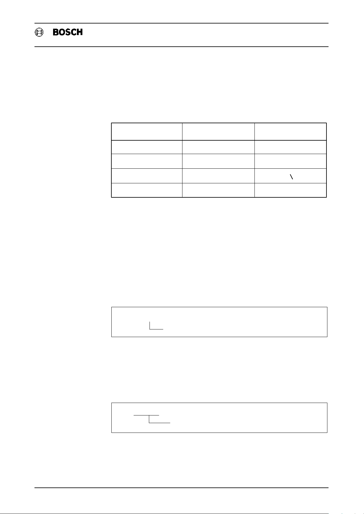
Flexible Automation
2. Basic Elements
CPL Programming Instructions
CC 220/320
point in decimal numbers and as a label identifier for jump destinations. The full
stop is interpreted as a punctuation character within character strings. In texts
(character strings), it is also possible to use the following characters: ~ ", ^" or
"", _" or z", ’ " or \". Differences between the keyboard symbol, representa
tion in NC mode and representation in graphic mode are shown by the following
table:
Constants
If numerical values are defined for the program sequence which are to remain un
changed (constant), it is possible to use these values in the instructions directly as
digits.
Integer constant (INTEGER)
Whole numbers (integers) are written without a decimal point.
Example:
Keyboard symbol
( Panel )
_
n
’
._.
Representation
in NC mode
z
"
’
:
Representation
in graphic mode
_
n
:
NUMBER% = 4
Floating−point constant (REAL)
Real numbers (decimal numbers or fractions) are identified by a decimal point
(floating point).
Example:
PI = 3.141593
INTEGER constant
REAL constant
2 − 6
Page 16

Flexible Automation
2. Basic Elements
CPL Programming Instructions
Double−precision constant and double−precision operations
Constants which are assigned to a double−precision REAL variable or which are
compared with a double−precision REAL variable are represented with double
precision (i.e. exact to 15 places).
If double−precision REAL constants are desired when calculating expressions in
comparisons (IF, WHILE, REPEAT), the following rules must be observed:
In the comparison, it must be ensured that a double−precision REAL variable is
contained on the far left of the expression which is processed first. It must be re
membered here that bracketed expressions are processed first. Equally, it must
also be remembered that the double−precision REAL constant must be pro
grammed on the right side (2nd operand) of the operands to be compared. If these
rules are not observed, the constants are interpreted as single−precision REAL
constants.
CC 220/320
Example: Assignment of double−precision REAL constants and comparison of
variables with double−precision REAL constants
4 D5! = –1234.123456 + 12345 + 1234.234567
20 D0! = 123456789.123456
22 D1! = 1.12345678901234
24 D2! = –123456789012345
26 D3! = –1234.123456
The following interrogations lead to the result: E? = TRUE
28 IF D0! = 123456789.123456 THEN E? = TRUE ELSE E? = FALSE ENDIF
29 IF D1! = 1.12345678901234 THEN E? = TRUE ELSE E? = FALSE ENDIF
30 IF D2! = –123456789012345 THEN E? = TRUE ELSE E? = FALSE ENDIF
31 IF D3! = –1234.123456 THEN E? = TRUE ELSE E? = FALSE ENDIF
32 IF D0! + 2.1 + 3.1 = 123456789.123456 + 2.1 + 3.1 THEN
33 E? = TRUE
34 ELSE
35 E? = FALSE
36 ENDIF
37 IF (D0! + 2.1) + 3.1 = 123456789.123456 + 2.1 + 3.1 THEN
38 E? = TRUE
39 ELSE
40 E? = FALSE
41 ENDIF
2 − 7
Page 17

Flexible Automation
2. Basic Elements
CPL Programming Instructions
CC 220/320
Example: Comparison of variables with single−precision REAL constants
20 D0! = 123456789.123456
22 D1! = 1.12345678901234
24 D2! = –123456789012345
26 D3! = –1234.123456
The following interrogations lead to the result: E? = FALSE:
42 IF 123456789.123456 = D0! THEN E? = TRUE ELSE E? = FALSE ENDIF
43 IF 1.12345678901234 = D1! THEN E? = TRUE ELSE E? = FALSE ENDIF
44 IF –123456789012345 = D2! THEN E? = TRUE ELSE E? = FALSE ENDIF
45 IF –1234.123456 = D3! THEN E? = TRUE ELSE E? = FALSE ENDIF
46 IF D0! + (2.1 + 3.1) = 123456789.123456 + 2.1 + 3.1 THEN
47 E? = TRUE
48 ELSE
49 E? = FALSE
50 ENDIF
46 IF 2.1 + D0! + 3.1 = 123456789.123456 + 2.1 + 3.1 THEN
47 E? = TRUE
48 ELSE
49 E? = FALSE
50 ENDIF
Character string constant (STRING)
A STRING constant is delimited by quotation marks.
Example:
EXAMPLE$ = "This is a character string"
Variables
If data is to be changeable (variable) during the program run, then such data items
are described using variables. Variables are arbitrary symbol names for which sev
eral conventions must be agreed in CPL. The most important convention is an un
ambiguous choice of the variable name. Variable names must not be reserved in
struction words (keywords). The variable name can consist of arbitrary letters and
digits, whereby a letter must be the first character. The first 8 characters of the vari
able name are significant, i.e. only these are used for distinguishing between vari
ables. The variable name itself may be longer, however, in order to permit better
documentation of a program. Conventions are also necessary as regards the
scope of variable action owing to the possibility of using subroutines and the pos
sible necessity of buffering variable values independently of the respective pro
gram.
STRING constant
2 − 8
Page 18

Flexible Automation
2. Basic Elements
CPL Programming Instructions
CC 220/320
A distinction is made between
‘ local variables
‘ global variables
‘ permanent variables
Local variables act only within the program in which they have been declared.
These variables are deleted after the program run when the program is quit and the
occupied program memory space is released again. In the case of a subroutine
call, a local variable name for the calling program is not defined for the subroutine
and may possibly be used again there. The original local variable is available again
with the value which it possessed directly before the subroutine call after the return
to the calling program. A 32 Kbytes memory location is available for local variables
in each program (subroutine).
Global variables are identified by a preceding # symbol followed by the variable
name. The stored values are preserved for the duration of a program run and can
be addressed by the main program and the related subroutine. Global variables
are no longer valid after the program end. A 32 Kbytes memory location is available
for global variables.
Permanent variables can be addressed by every active program under the desig
nation @1 ... @50. The variables of the INTEGER type are permanently preserved.
Deletion is possible only by specific overwriting. Permanent variables are not
stored in the variable memory area. Deletion of the whole memory therefore does
not affect permanent variables.
In order to permit the program to be read more easily, the designation of a perma
nent variable may be supplemented by appending letters to the number.
NUMBER% = 4
local INTEGER variable
#NUMBER% = 4
global INTEGER variable
36 = 4
@
permanent INTEGER variable
@
36QUANTITY = 4
permanent INTEGER variable
Depending on the type of data to be processed, it is expedient to reserve a suitable
memory area. Therefore, a distinction is made between variable types. In addition
to INTEGER variables, CPL features REAL, STRING, BOOLEAN and ARRAY vari
ables.
2 − 9
Page 19

Flexible Automation
Integer variable (INTEGER)
The INTEGER variable occupies 32 bits of memory space in each case. It is identi
fied by a % symbol attached to the variable name. The value range extends from
−2.147.483.648 to +2.147.483.647 .
Example:
NUMBER% = 4
Floating−point variable (REAL)
If no special identification follows the variable name, the variable is interpreted as a
REAL variable of single precision. In this case, the variable occupies 32 bits of the
memory area. The value range is +/−10
places before and after the decimal point.
2. Basic Elements
INTEGER variable
CC 220/320
CPL Programming Instructions
38
. This corresponds to 7 significant
Example:
PI = 3.141593
If a ! symbol follows the variable name, the variable is interpreted as a REAL vari
able of double precision. In this case, the variable occupies 64 bits of the memory
area. The value range is +/− 10
fore and after the decimal point.
Example:
PI! = 3.141592653589793
Logic variable (BOOLEAN)
Logic variables (BOOLEAN variables) can assume only one of the two values
TRUE and FALSE. They are used to store the truth value of assumptions which can
be tested later. Identification is done by means of a question mark following the
variable name.
REAL variable of single precision
308
. This corresponds to 15 significant places be
REAL variable of double precision
Example:
START? = FALSE
BOOLEAN variable
2 − 10
Page 20

Flexible Automation
2. Basic Elements
Character string variable (STRING)
A STRING variable is identified by a $ symbol following the variable name. The
pointer to the character string is stored in the variable if the variable is a simple,
non−dimensioned variable.
Example:
EXAMPLE$ = "This is a character string"
If the character string is a dimensioned field of characters (CHARACTER), these
characters can be processed with special character string instructions. (Refer to
the "Character string processing" section)
Example:
CC 220/320
CPL Programming Instructions
STRING variable
Array variable (ARRAY)
1 DIM ABC$(1)
2 DIM BCDE$(10)
3 ABC$ = ”Z”
4 BCDE$ = CHR$(90)
By using ARRAY variables, it is possible to reserve a one−dimensional or two−di
mensional field (ARRAY) in the memory area under a variable name. An array defi
nition is possible for REAL and INTEGER variables. The variable is indexed in order
to permit access to the individual array elements.
Example: Dimensioning an ARRAY variable
10 DIM ARRAYVAR(2,3)
INTEGER constants for array sizes (index)
Variable name (REAL variable)
DIM instruction word
Example: Access to ARRAY variables
.
100 ARRAYVAR(1,1) = MPOS(1)
110 ARRAYVAR(2,1) = CPOS(1)
120 ARRAYVAR(1,2) = MPOS(2)
130 ARRAYVAR(2,2) = CPOS(2)
140 ARRAYVAR(1,3) = MPOS(3)
150 ARRAYVAR(2,3) = CPOS(3)
2 − 11
Page 21

Flexible Automation
Overview of variables
2. Basic Elements
CPL Programming Instructions
CC 220/320
DIM
The index range or array size must be dimensioned before the first access to the
array variable with INTEGER constants. This is done with the DIM instruction.
DIM <variable name> (<array size1> [,<array size2>])
The following overview table summarizes the possibilities of using variables in
CPL:
Variable group Variable name Variablen type
Instructions
local
global #
permanent
arrays max. 8 characters
@
max. 8 characters
max. 8 characters
1 − 50
REAL single−precision
REAL double−precision
!
BOOLEAN
?
STRING
$
INTEGER
%
% INTEGER
$ CHARACTER
REAL single−precision
% INTEGER
It is possible to assign values to local and global variables. This is done with the
equals symbol =".
Example: Value assignment for a BOOLEAN variable
START? = FALSE
value
assignment symbol
(logic) variable
Example: Value assignment for a REAL variable
X1MIN! = 2097.876
value (max. 7 digits)
assignment symbol
double−precision REAL variable
Example: Value assignment between variables
XSET = XMIN!
value (double−precision REAL variable)
assignment symbol
single−precision REAL variable
2 − 12
Page 22

Flexible Automation
2. Basic Elements
The variable to which a value is to be assigned must be on the left−hand side, and
the respective value on the right−hand side of the assignment symbol. This con
vention must be observed in particular if a variable value is to be assigned to
another variable.
CPL Programming Instructions
CC 220/320
NUL
If no value has been assigned to the variable #VARIABLE, it has the value NUL
(zero), i.e. the statement »#VARIABLE = NUL« is true. We can see here that the
equals symbol can also be contained in comparisons or conditions.
If a local or global variable is to be selectively deleted, this can be done by assign
ment of the value NUL (zero). A permanent variable cannot be deleted, it can only
be overwritten.
Example: Deleting a variable
Mathematical operations
In addition to the assignment of a value as a constant expression (digits) or as a
variable, the value of a CPL expression can also be assigned to a variable. Func
tions with constants and variables may be contained in a single CPL expression.
The simplest functions include the basic mathematical operations:
Addition » + «
Subtraction » − «
Multiplication » * «
Division » / «
The mathematic rule of multiplication and division before addition and subtraction
applies. In addition, it is possible to use brackets, whereby 7−fold nesting is pos
sible for simple expressions (without function calls).
Example:
XSET = NUL
XSET = 4/(100–I%)+XACTUAL
In addition, it is also possible to call mathematical functions which act on variables,
constants, or CPL expressions located directly after the respective instruction word
in round brackets. The function always refers to the internal numerical representa
tion of the initial value. This can be checked during program execution using the
"Debug" function. In the case of nested expressions, particularly with function
calls, attention must be paid to the maximum possible nesting depth which de
pends on the memory space required by the bracketed expressions during execu
tion.
2 − 13
Page 23

Flexible Automation
2. Basic Elements
CPL Programming Instructions
CC 220/320
SQRT
This function is used to form the square root of an initial value. The initial value must
not be negative, since negative values are not defined.
Example: SQRT
XSET = 4*SQRT(100+I%)
ABS
This function serves to supply the absolute value of the initial value, i.e. negative
values become positive, positive ones remain positive.
Example: ABS
XVALUE = 2 * SQRT(ABS(100+I%))
ROUND
This function converts the initial value into a whole number (INTEGER) by rounding
up or down, The initial value may be a REAL expression.
Example: ROUND
XVALUE% has the value 11
XVALUE% = ROUND(10.9)
!
INT
This function converts the initial value (REAL) into a whole number (INTEGER) by
cutting off the decimal places (rounding down). The initial value may be a constant
or variable.
Example: INT
XVALUE% has the value 10
XVALUE% = INT(10.9)
!
SIN, COS, TAN, ASIN, ACOS, ATAN
In the case of trigonometric functions, which process angles in degrees, it is expe
dient to identify the angles as double−precision REAL variables. 5 places are sig
nificant with single precision, and 12 places with double precision. The following
trigonometric functions can be used:
SIN
COS
TAN
Example:
sine function
–
cosine function
–
tangent function
–
2 − 14
ASIN
ACOS
ATAN
arc sine function
–
arc cosine function
–
arc tangent function
–
Page 24
Flexible Automation
Logic operations
2. Basic Elements
YVALUE! = SIN(ANGLE!)
CPL Programming Instructions
CC 220/320
Logic operations can be performed in binary form with logic variables and in deci
mal form with INTEGER variables. They can be represented with the usual logic
operation symbols, the »·« symbol and the »+« symbol (−not in CPL−), as shown
in the description of the binary operations below. Here, too, »multiplication and di
vision are performed before addition and subtraction«, i.e. the AND operation acts
before the OR operation. Up to 7−fold bracket nesting is possible.
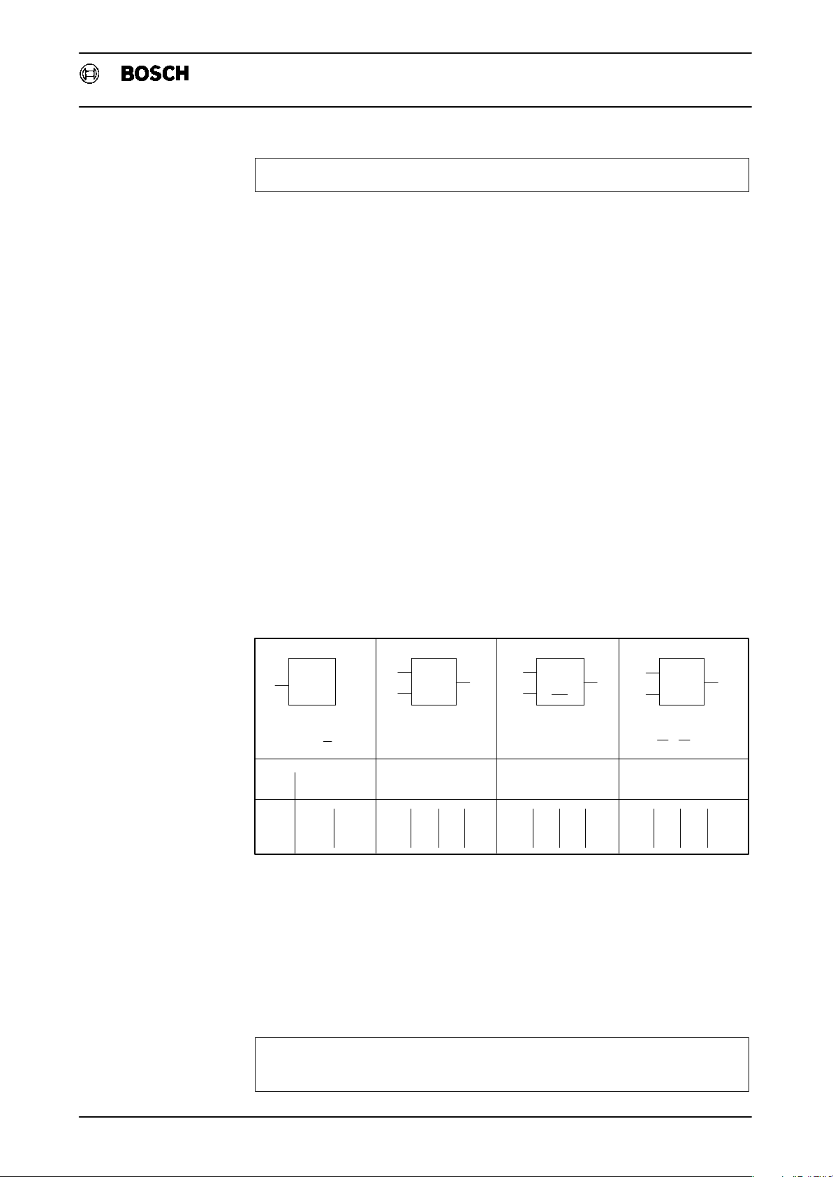
NOT, AND, OR, XOR
CPL provides four logic functions:
‘ the NOT function NOT ,
‘ the AND function AND ,
‘ the OR function OR
‘ and the EXCLUSIVE OR function XOR .
E1
E1
E2
A
1&>1=1
o− AA AA
NOT element AND element OR element XOR element
E1 = A E1 E1 + E2 = A E1
NOT AND OR XOR
0
−
L
E1 E1 E1
E2E2
.
E2 = A
0
L
−
0
0
L
0
0
0
L
0
L
0
L
L
0
0
L
0
L
0
E2
..
E2+E1 E2=A
L
L
0
0
L
L
L
0
L
L
L
0
L
0
L
0
0
L
Logic operations can be used for masking bits. Permanent variables are stored in
the dual−port memory area in the case of PLC coupling CC220/320−PC600 (refer
to respective manual). This area can also be addressed by the PLC. If certain signal
states are to be transferred from the PLC to the CC220/320, these can also be
coded in a permanent INTEGER variable. Logic operations are used in order to de
code these signal states again.
Example: Is bit 0 set in @20?
.
20 IF 20 AND 1 <> 0 THEN PRN#(0,”BIT 0 SET”)
30.ELSE PRN#(0,”BIT 0 NOT SET”) ENDIF
@
2 − 15
Page 25

Flexible Automation
Repeat instructions
2. Basic Elements
CPL Programming Instructions
CC 220/320
If one or more instructions − referred to as a "routine" in this manual − are to be
executed repeatedly under certain conditions, it is possible to program repeat in
structions. The repeated program run is also called a "loop".
REPEAT − UNTIL
If the loop abort condition is to be executed only after the routine has been exe
cuted for the first time, it is possible to say: "Repeat the routine until the condition is
satisfied !". The REPEAT loop thus has the following structure:
REPEAT <routine> UNTIL <condition>
Example: Programming a REPEAT loop
.
REPEAT
30
KEY%=INKEY
40
UNTIL KEY%=3
50
.
Wait loop until CTRL−C is pressed
WHILE − DO − END
If the abort condition is to be interrogated before the first loop run, the following de
scription would be possible: "While the condition is satisfied, do the routine!". The
WHILE loop is structured as follows:
WHILE <condition> DO <routine> END
Example: Programming a WHILE loop
.
WHILE IC(211)=TRUE DO
30
KEY%=INKEY
40
END
50
.
In both cases, the condition need not necessarily result directly from execution of
the routine, but may also be determined by the status of the interface signals or by
the changing value of a permanent variable. A condition may assume the state
»satisfied« or »not satisfied«. Interrogation for equality and inequality is permitted:
equals » = « greater than or equal to » >= « greater than » > «
not equal to » <> « less than or equal to » <= « less than » < «
Wait loop while interface 211 is high
2 − 16
Page 26

Flexible Automation
2. Basic Elements
CPL Programming Instructions
CC 220/320
FOR − STEP − TO − NEXT
If the abort condition is to result directly from routine execution, e.g., a tracking
counter is required which need not be programmed separately for the FOR−NEXT
loop. A counting variable (INTEGER) is defined whose initial and end counter val
ues must be specified. If the counting increment deviates from 1, the increment
(STEP) can be defined separately. The structure of a FOR−NEXT loop is as follows:
FOR <counting var.>=<initial value> [STEP <increment>] TO <end value>
<routine>
NEXT [<counting variable>]
Example: FOR−NEXT loop
.
FOR I%=1 TO 127
20
PRN#(1,”ORD.:”,I%,” CHAR.: ”,CHR$(I%))
30
NEXT I%
40
.
The characters with ordinal numbers 1 to 127 are written into a file. The ”I%" ap
pended to the ”NEXT” instruction in line 40 is only for clarity’s sake and can be
omitted.
It is also possible to program FOR−NEXT loops with variable step increments. The
step increment variable should be of the same variable type as the counting vari
able.
Example: FOR−NEXT loop with variable step increments
.
OPENW(1,”P222”,130,”TESTFILE”)
10
20
STEPNO%=2 : START%=1 : END%=3500 : NJUST
30
40
50
60
70
.
FOR COUNTER%=START% STEP STEPNO% TO END%
STEPNO%=ROUND(STEPNO%*SQRT(STEPNO%))
PRN#(1, ”COUNTER: ”,COUNTER%, ”INCREMENT: ”, STEPNO%)
NEXT
CLOSE(1)
The following is contained in the "Testfile" after execution of this program:
COUNTER: 1 INCREMENT: 3
COUNTER: 4 INCREMENT: 5
COUNTER: 9 INCREMENT: 11
COUNTER: 20 INCREMENT: 36
COUNTER: 56 INCREMENT: 216
COUNTER: 272 INCREMENT: 3175
COUNTER: 3447 INCREMENT: 178902
2 − 17
Page 27

Flexible Automation
Unconditional jump instruction
GOTO
Example: GOTO instruction
.
10
GOTO 120
.
10
GOTO N20
.
10.GOTO .DEST1
Unconditional program jumps are programmed with the GOTO instruction. A line
number, block number or label can be specified as the jump destination.
Label
2. Basic Elements
!
!
!
Jump to line 120
Jump to block N20
Jump to label .DEST1
CC 220/320
CPL Programming Instructions
A label can be written as a jump destination within a CPL block only. A label identi
fier consists of a space, decimal point and up to 8 significant ASCII characters,
whereby the first character must be a letter.
2 − 18
Page 28

Flexible Automation
Branch instruction
2. Basic Elements
CPL Programming Instructions
CC 220/320
IF − THEN − ELSE − ENDIF
A branch instruction can be formulated as follows:
If a certain condition is satisfied, then execute the routine, or else execute the other
routine!".
This results in the following instruction structure:
IF <condition> THEN <routine> [ELSE <alternative routine>] ENDIF
If the ELSE part is omitted, the program continues directly after the ENDIF instruc
tion in the event of non−satisfaction of the condition. Since a division in the pro
gram flow is involved in all cases with this instruction, it is called a branch. The
THEN and the ELSE routines are program branches which need not be processed
in all cases.
The condition is programmed in the same line as "IF". It is followed by "THEN" in
the same line.
Analogously to the abort conditions for the loop instructions, it is possible to use
arithmetic, trigonometric and logic operations in the condition of the IF instructions.
Nesting is also possible. The IF instruction can also be written without ELSE in
struction, however, it must always be terminated with an ENDIF instruction. Other
wise, the end of the routine or alternative routine will not be recognized. Since the
location of the ENDIF instruction depends on the program sequence logic, the
computer cannot always clearly recognize a missing ENDIF instruction. Mislead
ing error messages would occur in this case. The completeness of the IF instruc
tion must therefore be thoroughly verified by the programmer.
Example: Programming a loop with IF−THEN−ELSE−ENDIF
.
X = 1
10
.START
20
IF X>=100 THEN
30
40
50
60
70
90
.
.
ENDIF
.END
GOTO .END
ELSE X=X+2.75
GOTO .START
2 − 19
Page 29

Flexible Automation
2. Basic Elements
CC 220/320
CPL Programming Instructions
2 − 20
Page 30

Flexible Automation
3. Subroutines and Cycles
3. Subroutines and cycles
A subroutine call must always be contained in a separate block.
Calling subroutines with G, P or Q addresses
Pure CPL subroutines can be called from a DIN block via G22 or a P or Q address.
Refer to the Programming instructions P. − N o . 4219.
Up to 32 G functions can be defined in machine parameters P4000 to P4004 which
are then assigned to a specific part program number. It is also possible to deter
mine the number of parameters and a possible modal effect of the G function in this
definition. The modal effect of a G function is characterized by the fact that the part
program corresponding to the G function is called and executed after every NC
block containing an axis address.
Handling modal subroutine calls
CC 220/320
CPL Programming Instructions
The modal effect should be taken into account when calling other subroutines. It is
useful to cancel the modal effect by G80 before calling another modal G function in
order to avoid undesired superposition effects. It is necessary to distinguish be
tween subroutines executed from the part program memory and subroutines exe
cuted from the interface. Here are a few examples:
Examples: Modal subroutines executed from the part program memory
.
[
G81 1,2,3,4
N1
.
X100
N2
.
X110 P100
N3
.
X120 Q4711
N4
.
X130 G82 5,6,7
N5
.
X140 M321
N6
.
N7
G80
.
]
[
]
A modally active subroutine is pending
Positioning and execution of G81
Positioning and execution of G81 without execu
tion of subroutine 100
Positioning and execution of subroutine 4711 with
out execution of G81
Positioning and execution of G81 with subsequent
execution of G82
Positioning and execution of G81 without execu
tion of the subroutine call M321
The modal effect is canceled
3 − 1
Page 31

Flexible Automation
3. Subroutines and Cycles
Examples: Modal subroutines executed from the interface
.
G81 1,2,3,4
N1.
X100
N2
.
X110 P100
N3
.
X120 Q4711
N4
.
N5
X130 G82 5,6,7
.
N6
X140 M321
.
][
[]
Calling subroutines via any auxiliary or M functions
CC 220/320
CPL Programming Instructions
A modally active subroutine is pending
Positioning and execution of G81
Respective error messages:
RUNTIME ERROR 2140
MODAL SUBPRG.ACTIVE
A maximum of 16 M functions and 8 auxiliary functions can be defined via machine
parameters P4005 to P4009, i.e. they can be used for the assignment of addresses
and associated subroutines. M10, for example, can be used to call subroutine
P100. It is then only necessary to call the function in the main program in order to
execute the subroutine stored under that function.
Example: Calling a subroutine via an M function
.
X127 Y150 Z32 F2500
N20
M10
N30
N40
.
[20,2.3]
X110 Y120 Z0
Subroutine call with M function
with parameter transfer
Example: Calling a subroutine via any auxiliary function
.
X127 Y150 Z32 F2000
N20
B10
N30
N40
.
[20,2.3]
X110 Y120 Z0
Subroutine call by means of auxiliary
function with parameter transfer
CPL program execution parallel to machining time
The programs defined in machine parameter P4011 can be activated in the ,
, , modes and in the W.O.P . (workbench−oriented programming)
programming graphics by depressing the softkeys "PARAMETER IN DIALOG",
"CPL/DIALOG CALL", or "CYCLE". In turn, these programs can call other subrou
tines. Since the CPL programs started from the operating modes named above are
also executed simultaneously to a part program running in
possible to use any NC blocks in this case.
3 − 2
mode, it is not
Page 32

Flexible Automation
3. Subroutines and Cycles
Calling subroutines via the CALL function
CALL
Since NC blocks are not read when the CPL dialog is called in the above−named
operating modes, the CPL instruction CALL is required in order to call subroutines
in these modes. The CALL instruction must be located in a separate CPL block. The
keyword CALL is followed by the program number: this number may then be fol
lowed by parameters contained between square brackets..
Example: CALL instruction
.
50 IF A% = 1 THEN
5152CALL 999 2.75,X%,0
ENDIF
.
[]
CC 220/320
CPL Programming Instructions
Subroutine call with parameter transfer
The parameters transferred as a result of the subroutine call are initially always
called P1, P2, P3, etc. in accordance with the sequence of parameter transfer.
In subroutine P999, P1 thus has the value 2.75, P2 has the value of variable X% at
the time of parameter transfer, and P3 has the value 0. If P2 is to represent an IN
TEGER value in the subroutine as well, this may be done by appending a % symbol
to P2. This identification of the variable type is also possible analogously for the
other variable types.
Example: Parameter transfer in the subroutine
.
1 FACTOR=P1 : XVALUE%=P2% : COMPTAB%=P3%
11G1 X[XVALUE%*FACTOR]
G22 K[COMPTAB%]
.
3 − 3
Page 33

Flexible Automation
3. Subroutines and Cycles
CC 220/320
CPL Programming Instructions
3 − 4
Page 34

Flexible Automation
4. System functions
General
4. System Functions
CPL offers the possibility of accessing system data of the NC control. For some in
structions, however, the control used must have a bus link with the PC 600.
CPL Programming Instructions
CC 220/320
WAIT
WAIT(READY)
For some functions, it is necessary to stop block preparation and wait until the pre
vious blocks have been executed. This can be done by means of the ”WAIT” or
”WAIT(READY)” instructions. Both instructions have the same meaning. If the
control recognizes ”WAIT” or ”WAIT(READY)”, block preparation (max. 12
blocks) is stopped at this point until all blocks preceding ”WAIT” or
”WAIT(READY)” have been executed. Afterwards, block preparation continues
automatically. ”WAIT” or ”WAIT(READY)” only act in programs which were
started in the
WAIT(ACTIVE)
If, on the other hand, the system is to wait only until the previous NC block has been
prepared and is active − i.e. has not yet been executed − this can be achieved by
programming ”WAIT(ACTIVE)”. ”WAIT(ACTIVE)” also acts only in programs
which were started in the
WAIT([<IC condition>][,[<time>][,<result variable>]])
These parameters can be used in the following way:
If only one of the parameters is programmed, all commas on the left of the parame
ter must be used as dummies for non−programmed parameters. In contrast, there
must be no comma on the right of the last−programmed parameter.
Examples:
.
1 WAIT(,TIME%,E%) Application of parameters <time> and
.
1 WAIT(,TIME%) Application of parameter <time>
or modes. Otherwise, the instruction is skipped.
or modes.
<result variable>
If the parameters <IC condition> and <time> are used together, the following
blocks are not interpreted unless either the <IC condition> has been satisfied or
the <time> has elapsed.
4 − 1
Page 35

Flexible Automation
4. System Functions
CPL Programming Instructions
CC 220/320
The individual parameters are as follows:
The following syntax rule applies within the parameter <IC condition>:
[NOT] [(]IC(<number>)[)][= <status>]
<nummer> designates the bit number of a CNC input signal and can be an arbi
trary arithmetic expression, <status> is a BOOLEAN expression.
If <status> is omitted, the status of IC(<number>) is assumed as being TRUE.
The waiting time is specified in milliseconds in the parameter <time>. <time>
may be a whole−number arithmetic expression (INTEGER).
If the parameter <result variable> is used, the variable contained therein may be
interrogated with respect to the event which has occurred. This parameter can be
programmed only in conjunction with at least one of the other parameters.
The following variable values can be evaluated:
If the <result variable> variable has the value 0, the <IC condition> was already
satisfied when the call occurred.
If the <result variable> has the value 1, the <time> has elapsed.
If the <result variable> has the value 2, the interface signal has changed.
Example: WAIT
:
1 WAIT(IC(2)=TRUE)
:
1 WAIT(IC((A%+B%)*2)=(E1? OR E2?))
:
1 WAIT(NOT (IC(230)),,C%)
1 IF C%=0 THEN
1 DSP(10,10,”Cond. already satisf”)
1 ENDIF
:
1 WAIT(,TIME%,E%)
:
1 WAIT(IC(232)=E7?,250,ERG%)
1 IF ERG%=0 THEN
1 DSP(10,10,”Not waited!”):ENDIF
1 IF ERG%=2 THEN
1 DSP(10,10,”> 250 ms waited!”)
1 ENDIF
!
Wait until interface signal 2 is set.
!
Wait until the interface signal (A%+B%)*2 has
the value of the logic expression (E1? OR
E2?).
Wait until the interface signal 230 has the
!
value FALSE. The result variable C% supplies
either the value 0, if the condition was already
satisfied when the WAIT instruction was
called, or the value 2, if the condition was
satisfied during the wait.
Wait until the time TIME% has elapsed. The
!
result variable E% is assigned the value 1.
!
Wait until the interface signal 232 has the
value of variable E7? or 250 milliseconds
have elapsed. The value of the result variable
depends on the event which has satisfied the
condition.
4 − 2
Page 36

Flexible Automation
4. System Functions
CPL Programming Instructions
CC 220/320
Restrictions:
1. The WAIT function cannot be programmed with active cutter radius compensa
tion. If this restriction is not observed, the error message "TOO MANY BLOCKS
SUPPR." appears.
2. The programmed wait time is checked at intervals of 500 milliseconds.
3. The reaction time of the control to fulfillment of the enable condition for further
execution of the subsequent blocks depends on the control load and the respec
tive operating mode under which the CPL program was started.
Axis positions
Programs which were started under the
or modes are treated with
higher priority by the control operating system than programs started in all other
operating modes.
CPOS
The last programmed absolute position of the individual axes can be determined
via the instruction CPOS (−> command position = programmed axis setpoint).
The axis is addressed by a number which is appended in brackets. The corre
sponding axis address is defined in the machine parameters (P102).
Example: CPOS
.
X150
N2
XVALUE = CPOS(1)
30
.
.
X50
N1
G91 X10
N2
XVALUE = CPOS(1)
30
.
The last−programmed value for the X
!
axis (=150.0) is assigned to the vari
able XVALUE.
Absolute position of XVALUE is 60.0
!
MPOS
Interrogation of the current axis position referred to the reference point is possible
with MPOS. MPOS indicates the current actual value of the respective axis. In order
to ensure that the last position traversed to is stored, the WAIT instruction should be
programmed before MPOS. The axis address is defined in the machine parame
ters analogously to the CPOS instruction.
Example: MPOS
.
WAIT
20
XPOS = MPOS(1)
30
.
.
4 − 3
The current value of the X axis is as
!
signed to the variable XPOS
Page 37

Flexible Automation
4. System Functions
CPL Programming Instructions
CC 220/320
PPOS
If switching measuring probes are connected to terminal X51 of the control loop
board, the axis position is interrogated at the switching point of the measuring
probe with the PPOS instruction. The axis address is defined in the machine pa
rameters analogously to the CPOS instruction.
Example: PPOS
.
X250G75
80.WAIT : XMEAS = PPOS(1)
The X axis is traversed in the direction of the speci
!
fied position. When the measuring probe switches,
the current position is stored, the distance to go is
deleted and G75 is rendered inactive. The stored
position is transferred to the XMEAS variable.
AXO
Zero offsets
The AXO instruction permits interrogation of a G92 shift or a shift which was gener
ated by manual zeroing. The axis address is defined in the machine parameters
analogously to the CPOS instruction.
Example: AXO
.
G1 X100 Y200 F2000
G92
X75 Y125
90
XD = AXO(1):YD = AXO(2)
.
The variables XD and YD assume the current value of
!
the shift.
FXC
The "FXC" instruction provides direct access to the zero offset tables stored in the
NC. The instruction has the following structure:
FXC( <axis selection>[,<G address>[,<zero offset table>]])
<axis selection>: axis 1−8
<G address>: selection of G52−G259 (52,54..59, 60, 99, 154..159, 160, 254..259)
<zero offset table>: max. 8 characters
The addressed table can be read or overwritten. If it is overwritten, the old value can
be replaced by the new value, or the new value an be added to the old one. This can
be determined by means of the programmed <axis selection>. If the axis address
is positive, the programmed value is transferred to the zero offset table. If the axis
address has a negative sign, the programmed value is added to the table value. If
an active zero offset is to be overwritten, it must be guaranteed that only one G
group is active for the zero offset. Otherwise, an unambiguous assignment is not
possible.
4 − 4
Page 38

Flexible Automation
4. System Functions
CPL Programming Instructions
CC 220/320
If <zero offset table> is programmed with G functions 52, 60, 99, or 160, an error
message will be output.
Examples: FXC
The value 80 is stored under G54 in zero offset table
70 FXC(1,54,1) = 80
.
70 FXC(–2,54,1) = 80
.
70 A = FXC(1,54,1)
.
70 A = FXC(1)
.
!
1 for the X axis.
The value 80 is added to the old value under G54 in
!
zero offset table 1 for the Y axis.
!
The X value of the offset G54 is assigned from zero off
set table 1 to the variable A.
!
The total of the active table zero offsets, i.e. G53..59,
G153..159 and G253..259 plus active programmed
zero offset (G67, G60) plus active current external zero
offset (G167, G160) of the last prepared block is calcu
lated for the X axis.
The term "current" in the explanation of the FXC examples means . at the time of
CPL block preparation. Block preparation can be interrupted by the WAIT instruc
tion.
Tool compensations
TC
The TC instruction provides access to tool compensation tables.
The structure of the instruction is as follows:
TC(<selection>[,<group>[,<table>]])
<selection>: selection of compensation 1 − length compensation
2 − radius compensation
<group>: compensation group H or D (max. 3 characters)
<table>: compensation table (max. 9 characters)
The instruction for tool compensation values can be used like the instruction for
zero offsets, i.e. it is possible to read or overwrite table values or to change a value
additively. Abbreviated programming of the instruction is possible if the active or
highlighted tool compensation table is accessed.
Example: TC
!
10 TC(1,10,25) = A
20 TC(2,20,25) = B !
.
10 TC(1,10,25) = A
20 TC(2,20,25) = B
.
2030A = TC(1,10,25)
B = TC(2,10,25)
.
.30 TC(1,10) = A
.
.
30 B = TC(2)
The value of the variables A or B is assigned to com
pensation group 10 for H or D, respectively, in tool com
pensation table 25.
!
In this case, the value of A and B in the compensation
!
group is changed additively.
The values for H and D are transferred from compensa
!
!
tion group 10 in table 25 to the variables A and B.
The length compensation value in A is transferred to
!
compensation group 10 of the active compensation
table.
The active radius compensation value is transferred to
!
variable B.
4 − 5
Page 39

Flexible Automation
4. System Functions
CC 220/320
CPL Programming Instructions
!
WARNING !
Special feature of CC 220 T
Some of the parameters of the TC instructions have a different meaning or a differ
ent value range for the turning lathe control.
<selection>: Parameter selection
The admissible value range is 0...9 or −1...−5. Negative parameter numbers are
used for additive modifications of compensation, wear and radius data. The mean
ing of some parameter contents is different for turning and milling tools (complete
processing).
additive Turning tool Data type
0
1
2
3
4
5
6
7
8
9
−1
−2
−3
−4
−5
Tool position no.
LX−length compensation in X
LZ−length compensation in Z
DX−wear in X
DZ−wear in Z
R−tool nose radius
P−tool nose position (0...9)
S−spindle override (%)
F−feedrate override (%)
altern. compensation group
Milling tool<Selection>
Tool position no.
LX−length compens.in X
LZ−length compens.in Z
DL−length wear
DR−radius wear
R−cutter radius
P−cutter pos. (10, 11)
S−spindle override (%)
F−feedrate override (%)
altern. compensation group
<group>: Compensation group
The admissible value range is 1 up to the value defined in machine parameter 7501.
If <group> is omitted, the active compensation group is selected.
INTEGER
REAL
REAL
REAL
REAL
REAL
INTEGER
REAL
REAL
INTEGER
CS table
<table>: Compensation table
The admissible value range is 1...999 999 999. If <table> is omitted, the active
compensation table is selected.
TD
If a CS table is used in CC 220/320 M, it is possible to access this table with CPL.
The related instruction is as follows:
TD (<data selection>[,<group>[,<table number>]])
CS table organization
<group>
<Data selection>
1
2
3
...
max. 26
#1 #2 #3 ...
The data of the CS table can be read and overwritten. Since the structure of the CS
table can be freely defined, when working with the CS table attention should be
4 − 6
Page 40

Flexible Automation
4. System Functions
CPL Programming Instructions
CC 220/320
paid to the data type required by the CS table. If a table value in INTEGER format is
agreed in a line, for example, this must be observed when using variables in CPL.
Example: TD
.
30
A = TD(1,5,1)
.
.
30 TD(3,5,1) = A%
.
.
.
.
The value of the first column in group 5 of the
!
CS table is transferred to REAL variable A.
!
INTEGER format is defined in the third line of
group 5 of CS table 1. An INTEGER variable
must therefore also be chosen for transferring
values to the table.
80 TD(5,5,1) = 25
.
.
!
WARNING !
Special feature of CC 220 T
The number 25 is transferred to the corre
!
sponding table location in the correct format.
With CC 220 T, the TD instruction provides access to the tool life table.
TD (<data selection>[,<position no.>[,<table number>]])
<data selection>: Parameter selection
The admissible value range is 0...3 or −1...−2. Negative parameter numbers are
used for additive modifications of the tool life.
<Selection>
additive Turning / Milling Data type
Tool life setpoint
1
2
3
−1
Tool life actual data
−2
alternative tool (position no.)
<position no.>: Tool number
The admissible value range is 1 ... 99. If <position no.> is omitted, the active tool is
selected.
REAL
REAL
INTEGER
Active system data
<table number>:
The admissible value range is 1...999 999 999. If <table number> is omitted the
active table is selected.
SD
It is possible to use CPL to read active system data of the NC control using the SD
instruction. The instruction has the following structure:
SD(<group>[,<index1>[,<index2>]])
INTEGER values are output by the SD function.
4 − 7
Page 41

Flexible Automation
4. System Functions
CC 220/320
CPL Programming Instructions
Group Index1 Explanation
1
1...48
1
1
2
2
2
3
4
5
5
5
6 1...6
7
7
8
9
10
11 1
11
11 1
12
12 3
Index2
Active G functions for respective group
1
(see separate table)
Last−programmed G function
22...48
12
1
2
3
42
1
23
1
24
1
2
3
451
35
452
353
453
1
27
3
1
210
2
211
1
212
412
Last−programmed G function with index1=1 can be recognized
only directly in the following block. Otherwise, the value 0 is sup
plied. The SD function supplies the value −1 for non−applied G
groups.
31...481
G functions for switch−on state
Active override position for the respective potentiometer in percent
Feedrate
Rapid
Spindle (SD(2,3)=0 if no spindle is applied)
2nd spindle (SD(2,4)=0, if no 2nd spindle is applied
Number of the last−programmed tool compensation table
Number of the active tool compensation table
Number of the last−programmed zero offset table
Number of the active zero offset table
Active speeds (rounded to whole−number value)
1
1
1
251
2
1
1
2
2
Feedrate in input unit per minute: weighted with potentiometer.
If G63 is active, SD supplies the 100% value.
Rapid traverse in mm/min or inch/min (100% value)
Spindle speed in rpm; weighted with potentiometer.
(SD(5,3,1)=0 if no spindle is applied)
Spindle speed weighted with potentiometer (2nd spindle)
(SD (5,4,1)=0 if no 2nd spindle is applied)
Last−programmed speeds
Feedrate in input unit per minute
Spindle speed in rpm
(SD(5,3,2)=0 if no spindle is applied)
Spindle speed weighted with potentiometer (2nd spindle)
(SD(5,4,2)=0 if no 2nd spindle is applied)
Actual speed
Actual speed of 2nd spindle
Auxiliary functions
(Refer to machine parameters P2001 and P2004 for assignment
and transfer format)
Active tool
Last−programmed tool
Tool to be substituted (only with GO BLOCK/RE−ENTRY)
Last−selected main program number
for GOM EXECUTE: No. of the main program
for DA mode (DNC): No. of the DA main program
for GOM MANUAL INPUT: SD(8)=0
If neither a program nor MDI is active: SD(8)=1
Measuring probe switched: SD(9)=0 (G75 not active)
Measuring probe not switched: SD(9)=1 (G75 active)
Number of the last−programmed drilling axis
Number of active drilling axis
Main axis of the last−programmed plane change
Auxiliary axis of the last−programmed plane change
Main axis of active plane
Auxiliary axis of active plane
Active spindle direction of rotation
SD(12.1)= 3 M03/M13 programmed
SD(12.1)= 4 M04/M14 programmed
SD(12.1)= 0 M05/M19 programmed
SD(12.1)=−1 spindle not applied
SD(12.1)=−3 M03/M13 with same direction for M03/M04 or
SD(12.1)=−4 M04/M14 with same direction for M03/M04 or
SD(12.1)=19 M19 programmed
Last−programmed spindle direction of rotation
(All functions except −3 and −4 as for active spindle direction of
rotation). Reversal of the direction of rotation by means of an inter
face signal is not taken into account!
Active spindle direction of rotation (2nd spindle)
Last−programmed direction of rotation of 2nd spindle
M13/M14
M13/M14
4 − 8
Page 42

Flexible Automation
4. System Functions
Group Index1 ExplanationIndex2
13
CC 220/320
CPL Programming Instructions
Machining mode for execution at interpretation time
SD(13)=0 Single block, single step
SD(13)=1 Automatic
SD(13)=10 Go block with single block or single step
Selected block not yet interpreted.
SD(13)=11 Go block with automatic.
Selected block not yet interpreted.
14
15
16 0..1
17 1...32
20 1
21 1
.
.
999 999 999
.
.
999 999 999
1,−1
Number of active language
(in conjunction with the TXT$ instruction) (MPP 9915)
Test without movement
SD(15)=0 no
SD(15)=1 yes
Another computing run with subroutine call under Go block/re−
entry is to take place.
Index1=0 −>no
Index1=1 −>yes
The feedback value indicates which subroutine call can be executed
next.
Active G functions prior to entry into current Go block subroutine
Index1 = G function group: if no Go block subroutine is active,
0 will be fed back
Next free program number in P directory
Index1: Beginning of search (P no.)
Index2: 1 search forward
−1 search backward
If value −1 is fed back, there is no free program no. in this search
direction
File status and access privileges
Feedback value
0 ! no access privileges
−1 ! file does not exist
Binary evaluation of the feedback value:
bit1: file in use (G)
bit2: read access (R)
bit3: write access (W)
bit4: execute access (E)
bit5: delete access (D)
bit9: file in EEPROM or EPROM (K)
22 1...80 Access to the 80 INTEGER values stored in machine parameter
30 Serves to prevent G codes from being reset to switch−on state,
P4017, for example, machine−specific data to be considered in
the NC program.
braking of spindle or driven tool by the next M30 or program
deactivation. Precondition: NC input 6.4 "Clamp mode" is high. If
the feedback value is 1, the function was executed.
4 − 9
Page 43

Flexible Automation
4. System Functions
Examples: SD
.
10
A% = SD(1,2)
.
.
20 B% = SD(1,4) !
.
30 A% = SD(2,1)
.
40 B% = SD(5.1)
.
50 DUMMY% = SD(16,0)
60 DUMMY% = SD(16,1)
CPL Programming Instructions
The active G function from the index range
!
2 is contained in A%, e.g. the value 1, if G1
is active
B% contains either 90 or 91
!
A% contains the active position of the
feed potentiometer in %
!
The variable B% contains the active feedrate
!
No further computing run or subroutine call
!
Further computing run and subroutine call
CC 220/320
Supplementary table for interrogation of the active G functions of group 1:
Index G functions Index G functions
1
−
2
0−3, 5, 10−13, 33, 73
3
70, 71
4
90, 91
5
63, 66
6
140, 143..843,144..844
7
93−95
8
40−44
9
10
11
12
13
14
15
16
17
18
19
20
21
22
23
24
Programm example: SD (measuring probe interrogation)
.
N4 G75 X120
50
60
N7
80
90
100
110
.
6, 7
17−20
8, 9
25−27,125,126
14, 15
28, 29
78, 79
80−89
130−132
53−59
153−159
253−259
60, 67
37−39
61, 62
−
WAIT
IF SD(9) = 1 THEN
(MSG, MEASURING PROBE WAS NOT DEFLECTED)
GOTO .ERROR
ELSE
XMEAS = PPOS(1)
ENDIF
25
26
27
28
29
30
31
32
33
34
35
36
37
38
39
40
41
42
43
44
45
46
47
48
64, 65
68, 69
98, 99
145..845,146..846
114,115
160,167
490,491,993,994
51,52
−
−
−
−
−
−
−
−
−
−
−
−
−
−
−
−
In the SD example (measuring probe interrogtion), the X axis is traversed in the di
rection of the specified position. When the position is reached while the measuring
probe was not deflected, a message is output (line N7), and the program jumps to
the .ERRROR. label. If the measuring probe is deflected, the current position can be
stored in XMEAS.
4 − 10
Page 44

Flexible Automation
BIN, BCD
4. System Functions
CPL Programming Instructions
CC 220/320
The group number 6 of the SD function (auxiliary functions) is indexed in accor
dance with the auxiliary function address defined in the machine parameters
(P2001), i.e. the index corresponds to the input sequence there. The output value
of SD(6,<index1>) can be transferred to BCD format in accordance with P2004.
This format can be converted to binary format by the instruction
<binary value> = BIN(<BCD value>).
Conversely, it is also possible to convert binary format into BCD format. This is
done by means of the instruction:
<BCD value> = BCD(<binary value>)
!
Special feature of CC 220 T
T word, part counter data
WARNING !
Group Index1 ExplanationIndex2
7 1
72
73
140 1
140 2
141 <value>
142 <value>
143 <value>
144
145 1
145 2
146
147 1
147 2
147 3
147 4
Supplies the active T word
Supplies the prepared T word
Last tool before last tool change call (go block)
Supplies the current setpoint number of parts
Supplies the current actual number of parts
Sets the setpoint number of parts to <value>
Example: A%=SD(141,B%)
(Variable A% is only required to comply with the instruction format
of the SD instruction −> "dummy assignment")
Sets the actual number of parts to <value>
Example: A%=SD(142,B%)
(Variable A% is only required to comply with the instruction format
of the SD instruction −> "dummy assignment")
Sets the gear transmission of the driven tool to <value>
(Input of the 1000−fold value due to INTEGER representation)
Gear transmission (1000−fold value due to INTEGER)
Programmed speed of the driven tool
Setpoint speed of the driven tool
Minimum turning center distance in mm with active G491
Maximum compensation value in positive X direction
Maximum compensation value in negative X direction
Maximum compensation value in positive Y direction
Maximum compensation value in negative Y direction
4 − 11
Page 45

Flexible Automation
4. System Functions
CPL Programming Instructions
CC 220/320
SDR
The SDR function provides read access to system data in REAL format. The instruc
tion format and application correspond to those of the SD function.
SDR(<group>[,<index1>[,<index2>]])
Group Index1 ExplanationIndex2
1 1..8
2
2
2
1
2
3
42
Axis positions of all synchronous axes, which were calculated in the
Go block/re−entry function [index1 = axis number].
0 is returned without Go block function.
If a non−applied axis or an asynchronous axis is addressed, a
run−time error will occur.
Active override position for the respective potentiometer in percent
Feedrate
Rapid
Spindle (SDR(2,3)=0 if no spindle is applied)
2nd spindle (SDR(2,4)=0 if no 2nd spindle is applied)
4
4 1 1..8
4 2 1..8
51
5
5
12
12 1
0 1..8
2
3
451
35
452
Programmed zero offset values (G60)
Zero offset table value (G53..59, G154..159, G254..259)
External zero offset value (0 is supplied without word coupling)
(index2=axis number)
If a non−applied axis or an asynchronous axis is addressed, a
run−time error will occur.
If SDR (4....) is called up in the Go block/re−entry subroutine, the
active zero offset values will be output that have been active until
the Go block (inclusively) is reached. If the Go block has not yet
been calculated, the current program zero offset values will be out
put.
Active speeds (rounded to whole−number value)
1
1
1
251
2
353
354
Feedrate in input unit per minute: weighted with potentiometer.
(feedback value = contents of the F word)
If G63 is active, SDR supplies the 100% value.
Rapid traverse in mm/min or inch/min (100% value)
Spindle speed in rpm; weighted with potentiometer.
(SDR(5,3,1)= 0 if no spindle is applied)
Speed of 2nd spindle weighted with potentiometer
(SDR(5,4,1)= 0 if no 2nd spindle is applied)
Last−programmed speeds
Feedrate in input unit per minute
Spindle speed in rpm
(SDR(5,3,2)=0 if C axis is active or no spindle is applied)
Spindle speed in rpm (2nd spindle)
Actual spindle speed in rpm
SDR(5,3,3)=0 if C axis is active or no spindle feedback is
present or no spindle is applied
Actual 2nd spindle speed in rpm.
Last−programmed spindle position for M19
(0 is returned if M19 is not programmed)
Last−programmed position of the 2nd spindle for M19
4 − 12
Page 46

Flexible Automation
Variable axis address
4. System Functions
CPL Programming Instructions
CC 220/320
AXP
Using this function, part and measuring programs can be written on a plane−inde
pendent basis.
AXP(<axis number>,<position information>)
This function is used in an NC block. It must be written in square brackets "[ ]" and is
programmed instead of the address values.
Example:
.
N30 G90
N40
G1 AXP(A%,C) AXP(B%,D) F1000
[][]
N50
G20 G2 AXP(A%,E) AXP(B%,F) R RA
.
.
[][]
The axes determined by the variables A% and B% traverse to the position defined by
the variables C and D (line N40). Plane selection is then carried out by means of
A%, B% and G20, and the axes traverse in an arc defined by the variables E and F
(end point) and RA (radius).
][
PLC interface
Communication by means of variables
If word coupling between the CC 220/320 and the connected PC 600 is available,
both controls can access permanent variables stored in the communication
memory. The communication memory is a so−called dual−port RAM, a memory
area which can be accessed from two sides. The NC addresses this area from ad
dress 688000H to 68FFFFH on the one side, while the PC 600 accesses the same
memory area under the addresses C000H to FFFFH on the other side.
Storage formats in the dual−port memory
15
2
31
2
0
2
16
2
1st variable
2nd variable
.
.
4 − 13
Page 47

Flexible Automation
Interface access
4. System Functions
CPL Programming Instructions
CC 220/320
IC
The interface between the NC and PLC controls can be accessed by means of the
following instructions. All inputs and outputs of the NC control can be polled.
IC(<bit number>[<index>])
Example:
.
30 A?=IC(210) OR IC(211)
.
.
.
.
The meaning of the interface signals is described in "Interface conditions". The in
put bit 216.0 "Drive on 1st axis" corresponds to IC(0), while the state of input bit
247.7 can be polled correspondingly via IC(255).
The states of input bits 210 and 211 are log
ically combined with the OR function and
then assigned to the logic variable A?.
The output bits 205.0 (−>IC(232)) to bit 207.7 (−>IC(255)) can be set and reset if
this area has not been further restricted by machine parameter P4010.
Example:
.
30
IC(240)=TRUE
.
.
Output bit 206.0 is set
All output signals can be polled if an <index> with the value 0 is added. If the <in
dex> is 1, an input signal is read. Other <index> values are not admissible.
Example:
1 R%=0
1
S?=IC(233,R%)
!
Polling of an output signal
Output bits 207.6 and 207.7 are currently occupied by the drilling cycles G86 and
G84.
MIC
If a bidirectional transfer of max. 32 bits is to be carried out in parallel between the
NC and the PLC, the multi−interface can be used for this purpose. The time se
quence of the transfer and control signals is described in the "Interface conditions".
Example:
.
30 MIC = 12
.
.
40 MIC = A%
.
.
50 B% = MIC
.
.
A bit pattern representing the binary number 12 is assigned to
the multi−interface output.
The MI output can also be assigned INTEGER variables.
The current information at the MI input is assigned to the INTEGER
variable B%.
4 − 14
Page 48

Flexible Automation
Time recording
4. System Functions
CPL Programming Instructions
CC 220/320
The NC control processes data in binary form. If a BCD signal is present at the mul
ti−interface output, conversion with the BIN instruction must be carried out before
further processing. If a BCD signal is to be output at the multi−interface output by
the NC, conversion from binary into BCD code must be performed using the BCD
instruction.
DATE, TIME
The DATE and TIME instructions provide for an interrogation of the current values
for date and time.
Examples: DA TE / TIME
.
30 A$ = DATE
.
.
40 B$ = TIME
.
The STRING variable A$ is assigned the date in the
form DD.MM.
The STRING variable B$ is assigned the time in the
form HH.MM.SS.
CLOCK
The clock instruction permits interrogation of the current status of a time counter in
milliseconds. The counter is generated from the internal system time. The updating
time is twice the servo clock time.
Example: CLOCK
.
30 STARTTIME% = CLOCK
N4 G1 X50 Y70
50 WAIT :
.
The counter value is assigned to the STARTTIME% variable before execution of
block N4. After execution of block N4, the time counter is polled for a second time
and the time difference DIFF% is generated which is necessary for execution of
block N4.
ENDTIME% = CLOCK : DIFF% = ENDTIME%–STARTTIME
4 − 15
Page 49

Flexible Automation
4. System Functions
CC 220/320
CPL Programming Instructions
4 − 16
Page 50

Flexible Automation
5. String processing
The CHARACTER data type offers the possibility of forming character arrays
(fields) with a defined length and of processing these STRINGs. The implicit decla
ration of this data type is by means of a $ symbol as a suffix in conjunction with the
corresponding array dimensioning. A character array is thus a dimensioned
STRING variable. If there is no dimensioning, a STRING variable is involved.
The CPL instructions MID$, LEN, INSTR, ASC, STR$, VAL, and TRIM$ are available
for string processing.
Dimensioning character arrays
In order to index variables of the CHARACTER type and to process these − exclu
sively one−dimensional − arrays in the same way as character STRINGs, the char
acter array must be defined (dimensioned). This must be done using the DIM in
struction.
5. String Processing
CC 220/320
CPL Programming Instructions
Example:
1 DIM VWX$(14)
In this example, the maximum array length of the VWX$ is 14 characters. However, if
only the first three characters of the array are written, the character array VWX$ has a
length of 3 (= number of allocated components).
If the value range for the character array length of 1 to 127 is exceeded, the follow
ing error message appears:
RUNTIME ERROR 2155 − WRONG INDEX
Example: Character string dimensioning
1 DIM ABC$(1)
2 DIM BCDE$(10)
3 ABC$ = ”Z”
4 BCDE$ = CHR$(90)
Reading characters from an arbitrary location in a string
MID$
This function takes parts out of a <STRING expression> and outputs them as text.
The result may be transferred to a STRING variable or to a correspondingly dimen
sioned character array.If chaining (e.g. MID$(A$+B$,2,3)) is programmed
within the MID instruction, the result may only be assigned to a character array.
MID$(<STRING expression>,<starting point>[,<number of characters>])
5 − 1
Page 51

Flexible Automation
<starting point> defines the position within the character array <STRING expres
sion> from which the characters are to be taken. <number of characters> deter
mines the number of characters to be taken. If <number of characters> is not pro
grammed, all characters up to the length end of the character array are taken.
The value range for the 2nd and 3rd parameters includes INTEGER values be
tween 1 and 127. If this value range is exceeded, the following message appears:
RUNTIME ERROR 2184 − INVALID PARAMETER.
"NUL" is returned if a part of the character array is accessed which has not yet been
allocated.
Modifying character strings
MID$
5. String Processing
CC 220/320
CPL Programming Instructions
The MID$ instruction overwrites part of a character array.
MID$((<character array>,<starting point>[,<number of characters>])
The INTEGER expression <starting point> defines the position in the <character
array> as from which the characters are to be overwritten. The INTEGER expres
sion <number of characters> determines the number of characters to be overwrit
ten.
The value range for the 2nd and 3rd parameters includes INTEGER values be
tween 1 and 127. If this value range is exceeded, the following message appears:
RUNTIME ERROR 2184 − INVALID PARAMETER.
If the 3rd parameter <number of characters> is not programmed, all allocated
characters are entered in the <character array> provided that the dimensioning of
the character array is not exceeded.
The value of <starting point> may exceed the number of previously allocated com
ponents (length) by a maximum of 1.
Example:
1 DIM A$(10)
2 A$= ”ABC” Length of A$ is 3.
3 MID$(A$,4,3)=”DEF”
The 4th to 6th components of the character array are written. This is permitted since
the first three components have already been allocated.
Example:
1 DIM A$(10)
2 A$= ”ABC” Length of A$ is 3.
3 MID$(A$,5,3)=”DEF”
5 − 2
Page 52

Flexible Automation
An attempt is made to write the 5th to 7th components of the character array. How
ever, this leads to the error message
RUNTIME ERROR 2248 − CHAR.FIELD NOT ALLOCATED
since the 4th component has not yet been allocated.
If more characters are allocated than the permitted maximum length of the charac
ter array, these characters are discarded.
Length of a character string
LEN
LEN() specifies the number of characters in a STRING expression. The result is an
INTEGER value.
LEN(<STRING expression>)
5. String Processing
CC 220/320
CPL Programming Instructions
Example:
1 DIM XYZ$(10)
2 XYZ$=”ABC”
3 I%=LEN(XYZ$)
The INTEGER variable I% has the value 3
Search for a character string
INSTR
INSTR(<character string>,<STRING expression>[,<starting point>])
INSTR() searches a <STRING expression> for a <starting point> beginning at the
<character string> and outputs the position of the first character of the <character
string> found in the <STRING expression> as an INTEGER value. The value 0 is
output if the <character string> is not found. The <character string> can be pro
grammed as a STRING expression.
The value range for the 3rd parameter is 1 to 127. If this range is exceeded, the fol
lowing error message is displayed:
RUNTIME ERROR 2184 − INVALID PARAMETER.
Example: INSTR
1 DIM A$(8)
2 DIM B$(16)
3 A$ = ”A” : MID$(A$,2) = ”UVWXYZ”
4 B$ = ”ABCDEF UVWXYZ GH”
5 POSITION1% = INSTR(MID$(A$,2),B$,4)
6 POSITION2% = INSTR(MID$(A$,2,4),B$,10)
7 POSITION3% = INSTR(MID$(A$,2),B$)
Contents of the INTEGER variable POSITION1% : 8
Contents of the INTEGER variable POSITION2% : 0
Contents of the INTEGER variable POSITION3% : 8
5 − 3
Page 53

Flexible Automation
Character strings and numbers
ASC
ASC(<character string>)
ASC( ) outputs the ordinal number of the first character (ASCII code) of <character
string> as an INTEGER value.
<character string> must be a STRING expression. ASC( ) is a reversal of CHR$( ).
Example: ASC
10 DIM A$(1)
20 A$ = ”ABC”
30 B$ = ”BCD”
40 I% = ASC(A$)
50 J% = ASC(B$)
Contents of the INTEGER variable I% : 65
Contents of the INTEGER variable J% : 66
5. String Processing
CC 220/320
CPL Programming Instructions
STR$
STR$([<format string>,]<value>)
This function converts the numerical expression <value> into a character string
which can be assigned exclusively to a character array. Assignment to a STRING
variable results in a runtime error.
<value> may be an INTEGER or REAL expression with single or double precision.
If <format string> is programmed, the character string output can be formatted. In
this case, digits are represented by # and decimal points. If <format string> is not
programmed the output has the standard format.
Standard formats:
− INTEGER value: 9 places
− Single−precision REAL value: 4 places before the decimal point, 3 places after
the decimal point.
− Double−precision REAL value: 9 places before the decimal point, 6
places after the decimal point.
Example:
10 DIM A$(50)
20 DIM B$(21)
30 A$ = STR$(”Number = ##.###”,(37/3))
40 B$ = STR$(2.5)
Contents of the character array A$ : "Number = 12.333"
Contents of the character array B$ : " 2.500"
5 − 4
Page 54

Flexible Automation
5. String Processing
CPL Programming Instructions
CC 220/320
VAL
VAL(<STRING expression>)
VAL( ) returns the numerical value for a <STRING expression>. If a character other
than leading blanks, the leading characters "+" or "−", the digits 0 to 9 or the deci
mal point "." occurs in the character string, then conversion is performed up to this
(different) character. Leading blanks are ignored like leading zeros in value calcula
tion. "NUL" is returned if none of the above characters appears. If a decimal point
occurs in the character string, the result may only be assigned to a REAL or
double−precision REAL variable. In this case, assignment to an INTEGER variable
leads to the
RUNTIME ERROR 2175 − INVALID ALLOCATION.
Example:
1 I% = VAL(”1.23DE”)
2 K% = VAL(”123DE”)
3 J% = VAL(”ABC”)
4 R = VAL(”–1.23DE”)
5 Z = VAL(”+ 000001234TEST4365”)
6 X = VAL(”ABC1.23DE”)
7 D! = VAL(”1234567.234567”)
Line 1 causes a runtime error, since it is attempted to perform an assignment to an
INTEGER variable.
The value of the INTEGER variable K% is 123. The digits 1, 2, 3 are converted
into an INTEGER value. The character ”D” cancels conversion, since it cannot be
long to an INTEGER value. The following characters are not processed.
The value of the INTEGER variable J% is NUL − the variable has not been allocated.
The character ”A” aborts processing of the <STRING expression>.
The value of the REAL variable R is −1.23. The character "−" is recognized as a
sign for the REAL number. The digit 1, character ".", and the digits 2 and 3 are
converted into a REAL number. The character ”D” aborts conversion, since it can
not belong to a REAL number. The character ”E” is not processed.
The value of the REAL variable Z is 1234. The character "+" is recognized as a sign
for the REAL number. The following blanks are ignored like leading zeros in value
generation. The digits 1, 2, 3, and 4 are converted into a REAL number. The
character "T" aborts conversion since it cannot belong to a REAL number. The re
maining characters are not processed.
The REAL variable X is NUL, i.e. not allocated. Conversion is aborted after recogni
tion of the character ”A”.
The value of the double−precision REAL variable D! is 1234567.234567 .
5 − 5
Page 55

Flexible Automation
5. String Processing
Removal of leading or trailing blanks
TRIM$
TRIM$(<character string>)
TRIM$(<character string>,"L")
TRIM$(<character string>,"R")
TRIM$( ) supplies a character string without leading (−> index L) or trailing (−>
index R) blanks when a character array area is assigned to a STRING variable or
character array. The TRIM function without index suppresses both leading and trail
ing blanks.
If chaining (e.g. TRIM$(A$+B$)) occurs within the TRIM instruction, the result
must always be assigned to a character array.
Example:
1 A$ = ” ABCDEF ”
1 B$ = TRIM$(A$,”L”)
1 C$ = TRIM$(A$,”R”)
1 D$ = TRIM$(A$)
1 DSP(10,10,”>”,A$,”<”)
1 DSP(12,10,”>”,B$,”<”)
1 DSP(14,10,”>”,C$,”<”)
1 DSP(16,10,”>”,D$,”<”)
causes the following output:
> ABCDEF <
>ABCDEF <
> ABCDEF<
>ABCDEF<
CC 220/320
CPL Programming Instructions
Programming examples
A STRING expression can be assigned to a STRING variable.
Example: Programming STRING variables
To permit further processing of a dimensioned character array, it is necessary to
selectively access one or more coherent characters. Only then it is possible to as
(without previous dimensioning)
1 A$=”ABCDE”
2 B$=CHR$(10)
In the case of read access, it is possible to access parts of the STRING variables by means of
the MID$ instruction:
1 A$=”ABCDEFGHIJKLMN”
2 B$=MID$(A$,2,1)
3 C$=MID$(A$,4,4)
The following programming causes errors:
4 MID$(A$,1,4)=”ABCD”
4 A$=MID$(A$,1,3) + MID$(A$,4,1)
4 A$=B$ + A$
5 − 6
Page 56

Flexible Automation
5. String Processing
CPL Programming Instructions
CC 220/320
sign a character array or part of the character array to a STRING variable or a differ
ent character array.
Read and write access to part of a character array is performed by means of the
MID$ instruction. The entire character array is addressed if only the character array
name is specified.
Reading a character array
If the <n>th character of the character array is to be accessed, the following proce
dure must be followed (n is less than or equal to the length of the character array
and the number of array characters):
Example: Reading a character array
1 DIM VWX$(13)
2 VWX$=”TEST TEST TES”
3 A$ = MID$(VWX$,12,1)
4 I%=12
5 A$=MID$(VWX$,I%,1)
The 12th character (”E”) of the VWX$ character array is assigned to the STRING variable
A$.
If a coherent area of the character array (−> character string) is to be used, this can
be achieved using the MID$ instruction.
Example:
1 DIM A$(13):I%=10:J%=4:A$= ”TEST TEST TES”
2 B$=MID$(A$,I%,J%)
3 DSP(4,9,”>”,A$,”< (A$ previous.)”):DSP(6,9,”>”,B$,”< (B$ prev.)”)
4 A$=ABCDEFGHIJKLM”
5 DSP(8,9,”>”,A$,”< (A$ afterw.)”): DSP(10,9,”>”,B$,”< (B$ afterw.)”) The characters 10 to 13 (”TES”) of the character array A$ are assigned to the
STRING variable B$. It must be noted that the contents of B$ also change if the contents of the
character array A$ are changed.
Writing a character array
If the contents of a STRING variable are to be transferred to the character array or
part of the character array, the assignment must be changed around.
Example: Partial writing to a character array
1 DIM XYZ$(15)
2 B$=”ABCDE”
3 MID$(XYZ$,1,5)=B$
4 MID$(XYZ$,6,5)=B$
The 1st to 10th characters of the XYZ$ character array are assigned the contents of the
STRING variable B$.
The programming example shown below would lead to the error message
RUNTIME ERROR 2248 − CHAR.FIELD NOT ALLOCATED
since characters 1 to 5 of the character array have not been allocated:
5 − 7
Page 57

Flexible Automation
5. String Processing
1 DIM XYZ$(15)
2 B$=”ABCDE”
4 MID$(XYZ$,6,5)=B$
CPL Programming Instructions
CC 220/320
Example: Partial writing to a character array
1 DIM XYZ$(100)
2 B$= ”ABCDE”
3 MID$(XYZ$,1,10)=B$
Contents of the STRING variable B$: "ABCDE"
Contents of the array variable XYZ$:”ABCDE”. The array variable has a length of 5. The re
maining 95 characters have not been allocated.
The XYZ$ character array is written only with the length of the STRING variable if the
length of the STRING variable is smaller than that of the character array. If this char
acter array is assigned to a STRING variable, only the area which was written pre
viously (−> length of the character array) is allocated and not the whole character
array which was defined by the DIM instruction.
Example:
1 DIM XYZ$(100)
3 MID$(XYZ$,1,10)=”ABCDE”
4 MID$(XYZ$,6,3)=”T”
The contents of the XYZ$ array variable are ”ABCDE” after record 3. The array vari
able has a length of 5. The remaining 95 characters have not been allocated and
are therefore not included in the length.
The contents of the XYZ$ array variable are ”ABCDET” after record 4. The array
variable now has a length of 6. The remaining 94 characters have not been allo
cated and are therefore not included in the length.
Example: Overwriting a character array
1 DIM XYZ$(100)
3 MID$(XYZ$,1,10)=”1234567890”
4 MID$(XYZ$,3,3)=”T”
The contents of the XYZ$ array variable are ”1234567890” after record 3. The
array variable has a length of 10.
The XYZ$ array variable has the contents ”12T4567890” after record 4. The array
variable has a length of 10. The character ”3” is overwritten by ”T”. The charac
ters ”4” and ”5” are preserved.
Example: Prohibited access to the character array
1 DIM XYZ$(100)
3 MID$(XYZ$,1,6)=”ABCDEF”
5 MID$(XYZ$,9,5)=”TEST”
5 − 8
Page 58

Flexible Automation
5. String Processing
The XYZ$ array variable contains ”ABCDEF” after record 3. The array variable has
a length of 6.
After record 5, it is attempted to assign a constant to the 9th to 13th components of
the character array. However, this leads to the following error message:
RUNTIME ERROR 2248 − CHAR.FIELD NOT ALLOCATED
since the 7th and 8th components have not been allocated.
It is sufficient to specify the variable name if the whole character array is to be ac
cessed.
Assignment of a STRING expression to a character array
If fewer characters are contained in the STRING expression than in the selected
area of the character array, the remaining area is considered as not having been
allocated. This remaining area is not counted as part of the character array length.
CC 220/320
CPL Programming Instructions
Example:
1 DIM XYZ$(16)
2 XYZ$=” ”
Contents of the XYZ$ character array: ” ”
Length of the XYZ$ character array: 1
Any excess characters are discarded if the length of the STRING expression ex
ceeds the maximum length of the character array upon assignment.
Example:
1 DIM XYZ$(3)
2 XYZ$=”ABCDEF”
Contents of the XYZ$ character array: ”ABC”
Length of the XYZ$ character array: 3 −−−> maximum length
Example:
1 DIM XYZ$(14)
2 A$=”THIS ”
3 B$=”IS A TEST”
4 C$=”A POST”
5 MID$(XYZ$,1,5)=A$
CONTENTS OF THE CHARACTER ARRAY
–––––––––––––––––––––––––––––––––––––––––––––––––––––––––
| 1 | 2 | 3 | 4 | 5 | 6 | 7 | 8 | 9 |10 |11 |12 |13 |14 |
–––––––––––––––––––––––––––––––––––––––––––––––––––––––––
| | | | | | | | | | | | | | |
| T | H | I | S | | | | | | | | | | |
| | | | | | | | | | | | | | |
–––––––––––––––––––––––––––––––––––––––––––––––––––––––––
| | |
Length = 5 Area has not been allocated
5 − 9
Page 59

Flexible Automation
5. String Processing
CPL Programming Instructions
Example:
6 MID$(XYZ$,6,6)=B$
CONTENTS OF THE CHARACTER ARRAY
–––––––––––––––––––––––––––––––––––––––––––––––––––––––––
| 1 | 2 | 3 | 4 | 5 | 6 | 7 | 8 | 9 |10 |11 |12 |13 |14 |
–––––––––––––––––––––––––––––––––––––––––––––––––––––––––
| | | | | | | | | | | | | | |
| T | H | I | S | | I | S | | A | | T | | | |
| | | | | | | | | | | | | | |
–––––––––––––––––––––––––––––––––––––––––––––––––––––––––
| | |
Length = 11 Area has not
been allocated
7 MID$(XYZ$,6,9)=B$
CONTENTS OF THE CHARACTER ARRAY
–––––––––––––––––––––––––––––––––––––––––––––––––––––––––
| 1 | 2 | 3 | 4 | 5 | 6 | 7 | 8 | 9 |10 |11 |12 |13 |14 |
–––––––––––––––––––––––––––––––––––––––––––––––––––––––––
| | | | | | | | | | | | | | |
| T | H | I | S | | I | S | | A | | T | E | S | T |
| | | | | | | | | | | | | | |
–––––––––––––––––––––––––––––––––––––––––––––––––––––––––
| |
Length = 14 Area has been completely allocated
CC 220/320
8 MID$(XYZ$,9,4)=C$
CONTENTS OF THE CHARACTER ARRAY
–––––––––––––––––––––––––––––––––––––––––––––––––––––––––
| 1 | 2 | 3 | 4 | 5 | 6 | 7 | 8 | 9 |10 |11 |12 |13 |14 |
–––––––––––––––––––––––––––––––––––––––––––––––––––––––––
| | | | | | | | | | | | | | |
| T | H | I | S | | I | S | | A | | P | O | S | T |
| | | | | | | | | | | | | | |
–––––––––––––––––––––––––––––––––––––––––––––––––––––––––
| |
Length = 14 Area has been completely allocated
9 XYZ$=MID$(XYZ$,1,5)
CONTENTS OF THE CHARACTER ARRAY
–––––––––––––––––––––––––––––––––––––––––––––––––––––––––
| 1 | 2 | 3 | 4 | 5 | 6 | 7 | 8 | 9 |10 |11 |12 |13 |14 |
–––––––––––––––––––––––––––––––––––––––––––––––––––––––––
| | | | | | | | | | | | | | |
| T | H | I | S | | | | | | | | | | |
| | | | | | | | | | | | | | |
–––––––––––––––––––––––––––––––––––––––––––––––––––––––––
| | |
Length = 5 Area has not been allocated
The character array was cut off.
5 − 10
Page 60

Flexible Automation
5. String Processing
Comparison of STRING expressions
It is also possible to compare STRING expressions, i.e. STRING constants,
STRING variables and character arrays, with each other.
Example:
1 DIM A$(10)
2 DIM B$(15)
3 A$=”JAMES”
4 B$= ”BILLY”
5 C$=”ABCDE”
6 D$=”VWXYZ”
7 IF A$ < B$ THEN ...
8 IF MID$(A$,2,3) = MID$(B$,1,3) THEN ...
9 Z?=A$ <> ”TEST”
10 IF ”A” <= ”C” THEN ...
11 IF C$ > D$ THEN ...
12 IF A$ = C$ THEN ...
13 IF ”TE” < MID$(D$,2,2) THEN ...
CC 220/320
CPL Programming Instructions
The contents of the STRING expressions are verified for their alphabetical order
corresponding to the ASCII code of the individual characters.
Chaining STRING expressions
It is possible to chain several STRING expressions by means of the "+" symbol.
The result must be assigned to a character array. The nesting depth for chaining
STRING expressions is 3. If the nesting depth is exceeded, the following error mes
sage appears:
RUNTIME ERROR 2153 − NESTING TOO DEEP
Example: Chaining also within CPL instructions
1 DIM A$(3)
2 DIM B$(3)
3 A$ = ”ABC”
4 B$ = ”DEF”
5 C$ = ”GH”
6 D$ = ”JKL”
7 OPENW(1,”P2”,130,”TEST CHAINING”,10)
8 PRN#(1,A$+B$)
9 PRN#(1,A$+C$)
10 PRN#(1,C$+D$)
11 PRN#(1,A$+C$+”TEST”)
12 PRN#(1,”UVW”+”XYZ”)
13 CLOSE(1)
Contents of file P2:
ABCDEF <LF>
ABCGH <LF>
GHJKL <LF>
ABCGHTEST <LF>
UVWXYZ <LF><ETX><LF>
5 − 11
Page 61

Flexible Automation
5. String Processing
CPL Programming Instructions
Example: Chaining texts by means of STRING expressions
10 DIM A$(100)
20 DIM B$(100)
30 DIM C$(10)
40 DIM D$(20)
51 DIM E$(30)
52 DIM F$(30)
53 DIM G$(30)
54 DIM H$(30)
55 DIM I$(30)
60 A$=”THIS ”
70 B$=”IS A TEST”
80 MID$(C$,1,6)=A$ + B$
90 MID$(D$,1,10)=MID$(A$,1,1) + MID$(B$,1,2)
92 E$=A$ + MID$(B$,1)
93 X$=”ABC”
94 Y$=”DE”
95 F$=X$ + Y$
96 G$=X$ + A$
97 H$=X$ + A$ + ”TEST”
98 I$=”TES” + ”T1”
Contents of A$ : ”THIS ” Length 5
Contents of B$ : ”IS A TEST” Length 9
Contents of C$ : ”THIS I” Length 6
Contents of D$ : ”TIS” Length 3
Contents of E$ : ”THIS IS A TEST” Length 14
Contents of F$ : ”ABCDE” Length 5
Contents of G$ : ”ABCTHIS ” Length 8
Contents of H$ : ”ABCTHIS TEST” Length 12
Contents of I$ : ”TEST1” Length 5
CC 220/320
The following program leads to errors:
1 DIM A$(3):A$ = ”ABC”:B$ = ”CD”:C$ = ”EF”
1 D$ = A$ + B$
1 D$ = B$ + C$
1 D$ = A$ + B$ + ”TEST”
1 D$ = ”TEST” + ”TEST1”
inadmissible assignment to a non−dimen
sioned STRING variable
Example: STR$
1 DIM A$(50) : DIM B$(21)
1 A$ = STR$(”A$ = ##.###”,(37/3)) : B$ = STR$(2.5)
Contents of character array A$ : ”A$ = 12.333” ;
character array B$ : ” 2.500”
Example: VAL
1 DIM SEQUENCE$(20) : SEQUENCE$ = ”XVALUE –0001.234 MM”
1 X = VAL(MID$(SEQUENCE$,7)) : Z% = VAL(MID$(SEQUENCE$,7,7))
1 Y% = VAL(MID$(SEQUENCE$,15,5)) : X% = VAL(MID$(SEQUENCE$,18))
Contents of the REAL variable X : –1.234
Contents of the INTEGER variable Z% : –1
Contents of the INTEGER variable Y% : 234
Contents of the INTEGER variable X% : NUL
5 − 12
Page 62

Flexible Automation
5. String Processing
Example: LEN
1 DIM Z$(10)
2 Z$ = ”TEST”
3 S$ = ”TEST”
4 A% = LEN(”TEST”)
5 B% = LEN(Z$)
6 C% = LEN(S$)
7 D% = LEN(”TEST”+Z$+S$)
Contents of the INTEGER variable A% : 4
Contents of the INTEGER variable B% : 4
Contents of the INTEGER variable C% : 4
Contents of the INTEGER variable D% : 12
Example: MID$ instruction with read access
10 DIM A$(4)
20 DIM B$(10)
30 DIM C$(10)
40 DIM D$(10)
50 DIM E$(10)
55 DIM F$(10)
60 A$ = ”ABCD”
70 B$ = MID$(A$,2,2) ––> B$ = ”BC”
80 C$ = MID$(A$,2,5) ––> C$ = ”BCD”
95 E$ = MID$(A$,5,1) ––> E$ = NUL
97 F$ = MID$(A$,2) ––> F$ = ”BCD”
97 F$ = MID$(F$,1,1) ––> F$ = ”B”
CC 220/320
CPL Programming Instructions
Example: MID$ instruction with write access
10 DIM A$(4)
20 DIM B$(10)
30 DIM C$(10)
40 DIM D$(10)
60 A$ = ”ABCD”
70 B$ = ”1234567890”
80 C$ = ”EFGHIJKLMN”
85 D$ = A$ ––> D$ = ”ABCD”
90 MID$(D$,2,3) = B$ ––> D$ = ”A123”
95 MID$(D$,5,1) = C$ ––> D$ = ”A123E”
97 MID$(D$,4) = B$ ––> D$ =
”A121234567”
Example: TRIM$
1 DIM XYZ$(16)
2 XYZ$ = ”XVALUE = 0.123 ”
3 A$ = MID$(XYZ$,8)
4 B$ = TRIM$(MID$(XYZ$,8))
5 C$ = TRIM$(MID$(XYZ$,8),”L”)
6 D$ = TRIM$(MID$(XYZ$,8),”R”)
Contents of the STRING variable A$ : ” 0.123 ”
Contents of the STRING variable B$ : ”0.123”
Contents of the STRING variable C$ : ”0.123 ”
Contents of the STRING variable D$ : ” 0.123”
5 − 13
Page 63

Flexible Automation
5. String Processing
CC 220/320
CPL Programming Instructions
5 − 14
Page 64

Flexible Automation
6. File processing
The programming language CPL offers the possibility of reading data from the part
program memory or writing data to the part program memory. This is accom
plished by creating files. These files allow, for example, storage of measured values
and selective output on a printer at any time.
These files are handled in the same way as part program files, i.e. they can be man
aged under different operating modes. A file can be accessed once it has been
opened; when file processing is complete, the file must be closed.
Interface data
The two serial standard interfaces are treated like the files "1" and "2" in the "TTY"
directory.
Sequential file structure
6. File Processing
CC 220/320
CPL Programming Instructions
Random file structure
A sequential file contains a sequence of components (records) which may be of
variable length. If a certain record is searched in a sequential file, it is necessary to
search the file for this record from the start. Direct access is not possible. If the
length of a record is changed in a sequential file, all following records must be dis
placed.
In contrast to random files, sequential files contain records of different length (max.
length 127 characters). The end of a record is identified by <LF> which is not
counted as part of the length. An <ETX><LF> is inserted after the last record of a
file, representing an EOF pointer. An EOF pointer is a pointer for the end of the use
ful data (<ETX>) in a file.
A random file has components (records) with a fixed, definable length. Optional
direct access to any component in the file is thus possible. Subdivision of the ran
dom file into records with a fixed length permits direct access to a specific record.
The data is stored as ASCII characters, in the same way as for sequential files.
Thus, normal access using the editor as well as reading and writing of random files
is possible.
A random file has the advantage of faster access to the required data. In addition,
the data of a record can be processed and/or modified without changing the struc
ture of the rest of the file. Records which are not completely filled with data are filled
with blanks up to the defined length.
6 − 1
Page 65

Flexible Automation
Opening a file
6. File Processing
If it is attempted to insert a STRING variable in a random file which is longer than the
record length, the record is filled with the first characters of the STRING variable up
to the defined length, the remaining characters are discarded.
The file end is indicated by EOF when the file is read.
The REWRITE and CLOSE instructions are used in the same way as for sequential
files.
Sequential access to a random file is also possible.
CPL Programming Instructions
CC 220/320
OPENW, OPENR
If the file to be opened does not yet exist, it is created upon opening and the speci
fied memory space reserved. The command for opening a file depends on subse
quent read or write access.
Before write access −−> OPENW instruction
Before read access −−> OPENR instruction
Special feature of random files
Files of the RANDOM type can be opened only in the P directory, i.e. a record length
may only be programmed if P files are addressed. It is possible to additionally open
any files in the P directory which have already been opened for read access by
means of the OPENR instruction. However, an open file cannot be opened again for
writing.
The file pointer is positioned at the first record to which read access is possible
when a file is opened for reading.
The pointer is positioned at the EOF pointer, i.e. after the last file record, when a file
is opened for writing. An additional parameter is used to open a random file which
specifies the length of the records in the file in bytes (1 byte = length of a character).
Otherwise, the command format corresponds to that of a sequential file.
OPENW syntax
The OPENW instruction has two possible formats:
OPENW(<n>,<prog.identifier>[,<length>][,<program name>][,<record
length>])
or
OPENW(<n>[,<directory>],<file no.>[,<length>][,<program name>] [,<re
cord length>] )
6 − 2
Page 66

Flexible Automation
6. File Processing
<n>:
Logical number under which the file can be addressed. It is possible to choose val
ues between 1 and 9. The logical number must be programmed as an INTEGER
expression. A logical number must not be allocated for reading and writing a file at
the same time. In other words, up to 9 different files may be opened for reading or
writing. If the value range is not observed, the following error message is displayed:
RUNTIME ERROR 2221 − INVALID LOG.−NO.
<program identifier>:
The program identifier must be represented as a STRING expression (directory
and file no.), otherwise the following error message is displayed:
RUNTIME ERROR 2228 − INVALID FILENAME
<directory>:
The directory can be programmed as a STRING expression, or can be omitted. A
STRING constant must have the fixed structure ”P” or ”TTY” in order to be able to
open a file for writing. The character string ”P” or ”TTY” must therefore be as
signed to a STRING variable. If no directory is specified during programming, the P
directory is assumed implicitly. If these instructions are not observed, the following
error message is displayed:
CPL Programming Instructions
CC 220/320
RUNTIME ERROR 2228 − INVALID FILENAME
<file no.>:
The <file no.> must be represented as an INTEGER expression. If the TTY direc
tory was addressed, the <file no.> can only assume the INTEGER values 1 and 2.
TTY1 designates the serial interface on the control, while TTY2 describes the inter
face on the panel. If neither 1 nor 2 is programmed, the following error message is
displayed:
RUNTIME ERROR 2225 − INVALID DEVICE
Otherwise, the value range is 1 to 999 999 999. If the value range is exceeded, the
following error message is displayed:
RUNTIME ERROR 2228 − INVALID FILENAME
<length>:
Reserved length for file creation in bytes. If the P directory was previously pro
grammed in the 3rd parameter, the length must be programmed as an INTEGER
expression. A minimum length of 130 bytes is necessary since at least 1 record
(= 130 characters) is generated and stored when writing into the file. If these pa
rameters are not observed, the following error message is displayed:
RUNTIME ERROR 2226 − INVALID FILE LENGTH
6 − 3
Page 67

Flexible Automation
6. File Processing
If the TTY directory was programmed in the 3rd parameter, no length must be pro
grammed. Otherwise, the following error message will be displayed:
RUNTIME ERROR 2188 − PARAMETER MISSING
<program name>:
Only a STRING expression is permitted for programming the program name pa
rameter. The program name is automatically entered in the file header. If the TTY
directory was programmed in the 3rd parameter, no program name must be pro
grammed. Otherwise, the following error message will be displayed:
RUNTIME ERROR 2169 − ) MISSING
<record length>:
Number of bytes in a record; value range: 1...127.
If the value range is exceeded, the following error message will be displayed:
RUNTIME ERROR 2246 − INADM.COMPONENT LENGTH
CPL Programming Instructions
CC 220/320
A record length may only be programmed if P files addressed.
OPENR syntax
The OPENR instruction also has two possible formats:
OPENR(<n>,<prog.identifier>[,<record length>] )
or
OPENR( <n>[,<directory>],<file no.>[,<record length>] )
<directory>:
The directory can be programmed as a STRING expression, or can be omitted. A
STRING constant must have the fixed structure ”P” or ”L" or ”TTY” in order to be
able to open a file for reading. The character string ”P” or ”L" or ”TTL” must be
assigned to a STRING variable in order to permit a file to be opened for reading
interface data or the contents of another file. If no directory is specified when pro
gramming, the P directory is assumed implicitly. If these parameters are not ob
served, the following error message will be displayed:
RUNTIME ERROR 2228 − INVALID FILENAME
The remaining parameters can be used as for the OPENW instruction.
Below, there are a few examples on programming the OPENW instruction. They
can be transferred analogously to the OPENR instruction.
6 − 4
Page 68

Flexible Automation
6. File Processing
Examples: OPENW / OPENR
.
50 OPENW(1, ”P5”, 500,”POS”)
.
40
A$ = ”P5” : B$ = ”AXISPOS”
50
OPENW(9,AS,500,B$)
.
50
OPENW(8,TTY”,1)
.
50
OPENW(8,TTY1”)
.
40
A% = 5 : B$ = ”POSITIONS”
50
OPEMW(7,”P”,A%,500,B$)
.
40
A% = 5
50
OPENW(4,”P”,3+A%,250)
.
40
A$ = ”P”
50
OPENW(1,AS,5,500,”POS”)
.
40
A$ = ”TTY” : B% = 2
50
OPENW(3,A$,B%)
.
40
C% = 3 : A$ = ”P”
43
B% = 5 : L% = 500
48
Z$ = ”POS”
50
OPENW(C%,A$,B%,L%,Z$)
.
50
OPENW(3,5,500,”AXISPOS”)
.
40
A% = 5 : B% = 130
50
OPENW(4,A%,B%,”AXISPOS”)
.
40
A% = 3
50
OPENW(4,A%+2,500,”POS”)
.
CC 220/320
CPL Programming Instructions
When the file is opened for writing, the system verifies whether the random struc
ture is still preserved.
Example:
The record lengths of two OPENW instructions are not identical:
1 OPENW(2,2,200,”TEST”,10)
2 PRN#(2,”ABC”)
3 CLOSE(2)
4 OPENW(1,2,400,”TEST”,3)
5 CLOSE(1)
The system checks whether the record length of the "P2" file is 3. However, the record length
of this file is 10.
If the structure has been destroyed by means of the editor, the following error mes
sage is displayed:
RUNTIME ERROR 2246 − INADM. COMPONENT LENGTH
If addressing is performed via the program identifier or the TTY directory and a re
cord length is programmed simultaneously, the following error message is dis
played:
RUNTIME ERROR 2246 − INADM. COMPONENT LENGTH
6 − 5
Page 69

Flexible Automation
6. File Processing
CPL Programming Instructions
CC 220/320
Example:
10 OPENW(2,2,200,”TEST1”,10)
20 FOR I% = 1 TO 3
30 PRN#(2,”TEST”)
40 NEXT I%
50 CLOSE(2)
Result: ”P2”
TEST <LF>
TEST <LF>
TEST <LF>
<ETX><LF>
When a file is opened for reading, the system verifies whether the random structure
is retained. All components must have the same length as specified in the OPENR
instruction.
Example:
1 OPENW(2,2,200,”TEST”,10)
2 PRN#(2,”ABC”)
3 CLOSE(2)
4 OPENR(1,”P2”,5)
5 CLOSE(1)
The system checks whether the record length of the "P2" file is 5. However, the record length
of this file is 10.
Example:
P1:
N10 G1F10000X1000Y1000Z1000
1 A$=”01234567890123456789”
2 B$=”TEST”
N20 X0
M30
P2:
1 OPENW(1,3,500,”RANDOMFILE”,10)
2 OPENR(2,”P1”)
3 FOR I% = 1 TO 5
4 INP#(2,A$)
5 PRN#(1,A$)
6 NEXT
7 CLOSE(2)
8 CLOSE(1)
RESULT: P3
N10 G1F100<LF>
1 A$=”01<LF>
2 B$=”TE<LF>
N20 X0 <LF>
M30 <LF><ETX><LF>
6 − 6
Page 70

Flexible Automation
Writing a file
6. File Processing
If the structure has been destroyed by means of the editor, the following warning is
displayed
WARNING 2246 − INADM. COMPONENT LENGTH.
If the ’L’ directory is addressed and a record length is programmed simultaneously,
the following error message is displayed:
RUNTIM ERROR 2246 − INADM. COMPONENT LENGTH.
CPL Programming Instructions
CC 220/320
PRN#
Instruction format: PRN#(<n>,[<expression>] [,<expression>] [,<ex
pression>][,...][;])
<n>: Logical number of the file (value range 0...9)
<expression>: Any alphanumeric characters (text in quotation marks),
format strings or variables whose contents are to be
stored.
The variable type is freely selectable. It is also possible to use index variables and
character arrays. Furthermore, double−precision REAL expressions can be pro
grammed as arbitrary CPL expressions.
If the result of an expression is to be output with specification of a format, at least
one of the expressions must be of the STRING type. The format can be defined in
this format string by means of "#" and ".". The results are entered instead of the
format instruction defined with "#". The first format instruction contained in a
STRING expression refers to the first subsequent expression which can be output
with a format definition. Boolean expressions cannot be formatted. The number of
all programmed format definitions must be less than or equal to the number of ex
pressions to be output. If this condition is not satisfied, the excess "#" are dis
played. An expression is output in standard format if there is no format definition.
If the output of an expression contains more than 127 characters, the following er
ror message is displayed:
RUNTIME ERROR 2249 − BLOCK > 127 BYTE
If the result cannot be represented in the specified format, the following warning is
output:
WARNING 2213 − PRINT FORMAT WRONG
"*" characters will be output instead of the wrong format.
If # characters shall be generated within the file, no formatable expression may be
entered after the string within the PRN# instruction.
The character # can also be output via CHR$(35).
6 − 7
Page 71

Flexible Automation
6. File Processing
CPL Programming Instructions
CC 220/320
A line feed can be initiated during output by means of CHR$(13), i.e. output of the
PRN# instruction is continued in the next line, i.e. in the next record.
Using the CHR$() function, other control characters can also be transmitted, e.g.,
when outputting via a serial interface.
Automatic addition of a <CR><LF> is suppressed if a semi−colon is used after
the last expression of a PRN# instruction.
If a record is overwritten by means of the PRN# instruction, the following must be
taken into account:
PRN# instruction with semi−colon
If the length of the new data to be written is shorter than the length of the old data,
the new data is inserted and the rest of the old data is preserved.
Example:
1 OPENW(2,2,200,35)
2 PRN#(2,”TEST1 FOR PRN INSTRUCTION WITH SEMI–COLON”)
3 PRN#(2,”TEST2 FOR PRN INSTRUCTION WITH SEMI–COLON”)
4 PRN#(2,”TEST3 FOR PRN INSTRUCTION WITH SEMI–COLON”)
6 SEEK(2,1)
7 PRN#(2,”OVERWRITE”;)
8 CLOSE(2)
RESULT in P2:
OVERWRITE PRN INSTRUCTION WITH SEMI–COLON<LF>
TEST2 FOR PRN INSTRUCTION WITH SEMI–COLON<LF>
TEST3 FOR PRN INSTRUCTION WITH SEMI–COLON<LF>
<ETX><LF>
PRN# instruction without semi−colon
If the length of the new data to be written is shorter than the length of the old data,
the new data is inserted and the rest of the old data is overwritten with blanks.
Example:
1 OPENW(2,2,200,35)
1 REWRITE(2)
2 PRN#(2,”TEST1 FOR PRN INSTRUCTION WITHOUT SEMI–COLON”)
3 PRN#(2,”TEST2 FOR PRN INSTRUCTION WITHOUT SEMI–COLON”)
4 PRN#(2,”TEST3 FOR PRN INSTRUCTION WITHOUT SEMI–COLON”)
6 SEEK(2,1)
7 PRN#(2,”OVERWRITE”)
8 CLOSE(2)
RESULT in P2:
OVERWRITE <LF>
TEST2 FOR PRN INSTRUCTION WITHOUT SEMI–COLON <LF>
TEST3 FOR PRN INSTRUCTION WITHOUT SEMI–COLON <LF>
<ETX><LF>
An <ETX><LF> is inserted after the last record of the file
The following error message is displayed if the record length of 127 characters is
exceeded:
RUNTIME ERROR 2249 − BLOCK > 127 BYTE
6 − 8
Page 72

Flexible Automation
6. File Processing
CPL Programming Instructions
CC 220/320
If a sequential file is written and the file end reached, the file is automatically copied
and the reserved area is extended by the occupied length if sufficient memory
space is available in the part program memory. Since a large quantity of memory is
used up very rapidly as a result of this feature, it is advisable to reserve a sufficiently
large file length when the file is created with OPENW.
Example:
1 OPENW(1,”P2”,300,”TEST PRN INSTRUCTION”)
2 A$=”TEST”
3 B$=”FOR”
4 C$=”PRN INSTRUCTION”
5 PRN#(1,A$)
6 PRN#(1,B$)
7 PRN#(1,C$)
8 PRN#(1,A$;)
9 PRN#(1,B$;)
10 PRN#(1,C$;)
11 CLOSE(1)
RESULT:
P2:
TEST<LF>
FOR<LF>
PRN INSTRUCTION<LF>
TESTFORPRNINSTRUCTION<LF><ETX><LF>
Example:
10 DIM E$(50)
20 OPENW(1,2,300,”TEST2”)
30 A% = 5000
40 R = 1.231
50 B! = 4/3
60 D$ = ”ABCDE”
70 E$ = ”CDEFGHI”
80 PRN#(1,”10”;)
90 PRN#(1,”#####”,”###.###”,”#.#####”,A%,R,B!,D$,E$)
95 CLOSE(1)
P2 :
10 5000 1.2311.33333ABCDECDEFGHI<LF>
A% R B! D$ E$
6 − 9
Page 73

Flexible Automation
6. File Processing
CPL Programming Instructions
CC 220/320
Logical number "0"
If the logical file number "0" is used in a part program running in EXECUTE mode,
this file must not be opened or closed, since the text and/or variables are shown in
the "prompt line".
Example: PRN#(0,...)
.
1
TIME$=TIME
2
PRN#(0,”The time: ”,TIME$)
.
leads to the following "prompt line" output:
The time: 15:03:16
If "Parameter in dialog" is called in EDIT mode, a subroutine defined in machine
parameter P4011 is called. If the instruction "PRN#(0,...)" is used in this subrou
tine, the block is replaced by text and/or variables in the edited program text in
which the cursor was positioned when the "Parameter in dialog" softkey was
pressed, except for the N address. This feature can be used as a programming aid
for subroutine calls with numerous transfer parameters.
Example: Parameter in dialog
.
206 VX=11 : VL=5
306 B=(VX+VL)/2
406
PRN#(0,”Q510 ”,VX,”,”,VL,”,”,B,”
.
has the following result in the edit memory after termination:
.
N140 Q510 11,5,8
.
.
[]
[]
Assignment, e.g. after dialog input
”)
Texts
Variables
Cursor position before termination
LJUST, NJUST
Changeover to left−justified data output is performed with LJUST (=left JUSTifica
tion). This changeover takes effect for all file outputs up to the end of the program
run. It is possible to switch back to the formatted output mode before that by means
of NJUST (No JUSTification).
A maximum of 7 places (4 places before the decimal point, 3 places after the deci
mal point) is available for output of data to files for the REAL data type. A maximum
of 9 places is available for the INTEGER data type. Leading and trailing zeros are
suppressed. This also applies to left−justified output.
LJUST offers the possibility of generating NC programs which can be executed in
EXECUTE mode directly with CPL since spaces between the NC address and the
value are suppressed.
6 − 10
Page 74

Flexible Automation
Reading a file
6. File Processing
CPL Programming Instructions
CC 220/320
REWRITE
If data already exists in the opened file, the new data is normally appended to the
existing data by writing. However, an existing file can be overwritten with REWRITE
without the necessity to previously delete the no longer required contents sepa
rately. If a file is overwritten, the area in the part program memory reserved by the
OPENW instruction is preserved.
Instruction format: REWRITE(<n>)
<n>:Logical number of the file (value range 1...9)
The file must be opened before it can be overwritten.
INP#
Data can be read out of the file using the following instruction:
Instruction format: INP#( <n>,<variable>[,<variable>][, ...][;])
<n>: Logical number of the file (value range 0...9)
<variable>: Variable under which the data read is stored.
Using the INP# instruction it is possible to read the ASCII data of an open file (log
ical number 1 to 9) in the form of records and to assign it to one or more variables.
The variable type can be freely selected. Index variables and character arrays can
also be used. If a value other than TRUE or FALSE is assigned to a logical variable,
the value NUL is assigned to this variable.
In the case of variable type INTEGER or REAl (simple and double precision), the
characters "0" ... "9", leading signs "−", "+", leading zeros or blanks are converted
into INTEGER or REAL values. If a different character is assigned to an INTEGER or
REAL variable, the value NUL is assigned to this variable. The position within the file
does not change if NUL is assigned to a variable.
If an excessively large value is assigned to an INTEGER or REAL variable, a corre
sponding runtime error is displayed:
RUNTIME ERROR 2258 − INV. INTEGER VALUE
RUNTIME ERROR 2196 − INVALID REAL−VALUE
If a semi−colon is programmed, the file pointer remains in the record until the re
cord end is reached. Then the next record is processed. However, reading is not
automatically continued. The next record is automatically processed if no semi−
colon is programmed. Only one semi−colon is permitted per INP# instruction.
6 − 11
Page 75

Flexible Automation
6. File Processing
CPL Programming Instructions
Example: Reading a record out of a file
1 OPENW(1,2,200,”TEST”,22)
2 PRN#(1,”–12TEST1.23V12ABCD2.4A”)
2 PRN#(1,”–12TEST1.23V12ABCD2.4A”)
2 PRN#(1,”–12TEST1.23V12ABCD2.4A”)
3 CLOSE(1)
4 DIM A$(3)
5 DIM C$(5)
6 DIM D$(4)
6 DIM E$(4)
8 DIM H$(7)
9 DIM I$(7)
10 DIM R(1,2)
11 OPENR(2,2,22)
12 INP#(2,B%,D$,R(1,1),MID$(E$,1,1),R(1,2),A$,C$)
13 INP#(2,G$)
14 INP#(2,H$;)
15 INP#(2,I$;)
16 INP#(2,J$)
13 CLOSE(2)
CC 220/320
Result:
B% = –12
D$ = ”TEST” ,since max. length of the character array = 4
R(1,1) = 1.23
E$ = ”V”
R(1,2) = 12
A$ = ”ABC” ,since max. length of the character array = 3
C$ = ”D2.4A”
G$ = ”–12TEST1.23V12ABCD2.4A”
H$ = ”–12TEST” ,since max. length of the character array = 7
I$ = ”1.23V12” ,since max. length of the character array = 7
J$ = ”ABCD2.4A”
Example: INP# instruction
P2:
ABC 123456789 ABC
P3:
1 OPENR(2,2)
2 DIM C$(3)
3 INP#(2,I%,J,L?,C$,K%,D$)
4 CLOSE(2)
RESULT:
I% = NUL
J = NUL
L? = NUL
C$ = ”ABC”
K% = 123456789
D$ = ” ABC”
6 − 12
Page 76

Flexible Automation
6. File Processing
CPL Programming Instructions
CC 220/320
Logical number "0"
If "Parameter in dialog" is selected in mode DATA I/O (EDIT), it is possible to read
already allocated call parameters for creation of subroutine calls with the dialog
program stored under this function and to transfer these to specified variables. For
this purpose, the logical number 0 must be selected. Files must not be opened or
closed.
Instruction format: INP#(0,P1[,P2][,P3][,...])
By this instruction, parameter values can be preallocated and displayed in dialog
for a subroutine call without having to reenter them. The parameters read are as
signed to the corresponding CPL variables P1, P2, P3, etc. These can assume
only numerical or binary values. Identification of the variable type is possible by ap
pending the corresponding characters. If no value is found for a variable, an invalid
value is read or the instruction is used in a dialog program which does not run un
der EDIT, the corresponding variable(s) is/are preallocated with NUL.
Reading interface data
INP# function
If one of the two standard interfaces is selected in the OPENR instruction, it is pos
sible to determine the interface status by means of the INP# function.
Instruction format: [<return value>=]INP#( <n>,<variable>[,<variable>]
[, ...][;])
Except non−dimensioned STRING variables, all variable types are permitted as
<variable>.
If no character is received within the period specified in machine parameter P5504,
the INP# function returns the value 0. If characters are read in within this period,
however, the return value is a One. Otherwise, the syntax corresponds to that of the
INP# instruction.
Example: Reading from and writing to interface 1
1 DIM A$(10)
1 OPENW(2,”TTY”,1)
1 OPENR(3,”TTY”,1)
1 OPENW(4,4711,130,”TEST FILE”)
1 REWRITE(4)
1 FOR I%=1 TO 100
1 C%=INP#(3,A$)
1 IF A$<>NUL THEN
1 PRN#(2,A$,I%)
1 PRN#(0,A$,”<=======>”,C%)
1 DSP(15,15,A$)
1 DSP(17,15,I%)
1 PRN#(4,A$,I%)
1 ENDIF
1 NEXT I%
1 CLOSE(2) : CLOSE(3) : CLOSE(4)
M30
6 − 13
Page 77

Flexible Automation
6. File Processing
CPL Programming Instructions
Example: Reading from interface 2 and writing to interface 1
1 DIM A$(10)
1 OPENW(2,”TTY”,1)
1 OPENR(3,”TTY”,2)
1 OPENW(4,4711,130,”TEST FILE”)
1 REWRITE(4)
1 FOR I%=1 TO 100
1 C%=INP#(3,A$)
1 IF A$<>NUL THEN
1 PRN#(2,A$,I%)
1 PRN#(0,A$,”<=======>”,C%)
1 DSP(15,15,A$)
1 DSP(17,15,I%)
1 PRN#(4,A$,I%)
1 ENDIF
1 NEXT I%
1 CLOSE(2) : CLOSE(3) : CLOSE(4)
M30
CC 220/320
File end recognition
Closing a file
EOF
Using the EOF function, it is possible to inquire whether the end of a file (EOF . end
of file) has been reached. The EOF function results in the output of the logical value
TRUE if the file end is reached during read access. Otherwise, FALSE is output.
Example:
.
1
OPENR(1,”L”,444) : I%=4
1
WHILE NOT (EOF(1))DO
1
INP#(1,A$)
1
I%=I%+1
1
IF I%>36 THEN CLS : I%=5 ENDIF
1
DSP(I%,1,A$)
1
END
1
REPEAT UNTIL INKEY<>0
1
CLG:CLOSE(1)
M30
.
CLOSE
The file must be closed when read or write operations are terminated. This prereq
uisite must be met in order to be able to access a file again in a similar way.
Instruction format: CLOSE(<n>)
<n>: logical number of the file (value range 1...9)
6 − 14
Page 78

Flexible Automation
6. File Processing
CPL Programming Instructions
CC 220/320
Example:
.
90
WAIT
100
XPOS = MPOS(1)
110
YPOS = MPOS(2)
120
OPENW(1,”P5”,500,”AXISPOS”)
130
REWRITE(1)
140
PRN#(1,”X AXIS”,XPOS,”Y AXIS”,YPOS)
150
CLOSE(1)
160
OPENR(1,”P5”)
170
INP#(1,A$)
180
CLOSE(1)
190
OPENW(2,”TTY1”)
200
PRN#(2,A$)
210
CLOSE(2)
.
In the above example, the current positions of the X axis and the Y axis are trans
ferred to variables (lines 90 to 110). Then, file 1 is opened and stored as part pro
gram No. 5 in directory P (line 120). The file is then written or overwritten and finally
closed (lines 140 to 150). The file is subsequently opened for reading, and the con
tents are assigned to the variable A$. It is closed again after read access (lines 160
to 180). The serial interface at the control is opened in lines 190 to 210 and an in
struction for output of variable A$ is issued. The interface is then closed.
Reading the file pointer position
FILEPOS
The FILEPOS( ) function supplies the record number of the current record of a ran
dom file to which access is subsequently possible. In addition, it is possible to de
termine the record offset within the current record of a random file or with respect to
the current byte of a sequential file with the possibility to access this byte. The file
may be either a sequential file or a random file.
The term "Offset" is understood to mean the number of bytes from the start of the
file up to the current byte in a file. The record offset specifies the byte to which posi
tioning is to take place within a record. The record offset starts with the value 1 (=
1st byte in a record) and may assume a maximum value of the record length +1
(last byte in this record is <LF>). The value 1 is returned if the file pointer is located
at the EOF pointer.
Instruction format: FILEPOS(<n>[,<mode>])
<n> =Logical file number
Value range: 1..9
If the value range is exceeded, the following error message is displayed:
RUNTIME ERROR 2221 − INVALID LOG.−NO.
<mode> = Mode
If the value range (1..3) is exceeded, the following error message is displayed:
RUNTIME ERROR 2184 − INVALID PARAMETER
6 − 15
Page 79

Flexible Automation
6. File Processing
If <mode> is not programmed and the file is a sequential file, the instruction sup
plies the offset (
respect to the current byte which can be read or written.
If <mode> is not programmed and the file is a random file, the instruction supplies
the record number of the current record which can be read or written. If the EOF
pointer has been reached, the result is: number of records +1.
If <mode> is programmed and the file is a sequential file, only the value 1 must be
programmed for the <mode> parameter. The instruction then supplies the offset
. number of bytes from the start of the file to the current byte) with respect to the
(
current byte which can be read or written.
If <mode> is programmed and the file is a random file, the <mode> parameter
has the value range 1 to 3.
<mode> = 1:
. number of bytes from the start of the file to the current byte) with
CPL Programming Instructions
CC 220/320
The instruction supplies the offset (
current byte) with respect to the current byte which can be read or written.
<mode> = 2:
The instruction supplies the record number of the current record which can be read
or written. If the EOF pointer has been reached, the result is: number of records +1.
<mode> = 3:
The instruction supplies the record offset within the current record which can be
read or written. The record offset starts with the value 1 (
and can have a maximum value of the record length +1 (
<LF>). If the EOF pointer has been reached, the value 1 is returned and reading
out of the file is not permitted.
. number of bytes from the start of the file to the
. 1st byte in this record)
. last byte in this record is
6 − 16
Page 80

Flexible Automation
6. File Processing
CPL Programming Instructions
CC 220/320
Example: FILEPOS and sequential file
1 OPENW(1,2,200,”TEST”)
2 FOR I%= 1 TO 10
3 PRN#(1,”TEST FOR FILEPOS”)
4 NEXT
5 SEEK(1,3)
6 POSITION% = FILEPOS(1)
7 POSITION1% = FILEPOS(1,1)
10 PRN#(1,”OVERWRITE THE 3RD RECORD AS FROM BYTE 2 WITH THIS TEXT”)
11 SEEK(1,0) : REM POSITIONED TO FILE END
6 POS% = FILEPOS(1)
7 POS1% = FILEPOS(1,1)
11 CLOSE(1)
Result:
POSITION% = 3 −> Byte number
POSITION1% = 3 −> Byte number
POS% = 181 −> Byte number
POS1% = 181 −> Byte number
Example: FILEPOS and random file
1 OPENW(1,2,200,”TEST”,127)
2 FOR I%= 1 TO 10
3 PRN#(1,”TEST FOR FILEPOS”)
4 NEXT
5 SEEK(1,3,2)
6 POSITION% = FILEPOS(1)
7 POSITION1% = FILEPOS(1,1)
8 POSITION2% = FILEPOS(1,2)
9 POSITION3% = FILEPOS(1,3)
10 PRN#(1,”OVERWRITE THE 3RD RECORD AS FROM BYTE 2 WITH THIS TEXT”)
11 SEEK(1,0) : REM POSITIONED TO FILE END
6 POS% = FILEPOS(1)
7 POS1% = FILEPOS(1,1)
8 POS2% = FILEPOS(1,2)
9 POS3% = FILEPOS(1,3)
11 CLOSE(1)
Result:
POSITION% = 3 −> Record number of the record in which the user is located
POSITION1% = 258 −> Byte number
POSITION2% = 3 −> Record number of the record in which the user is located
POSITION3% = 2 −> Position within the 3rd record
POS% = 11 −>Record number of the record in which the user is located
POS1% = 1281 −> Byte number
POS2% = 11 −> Record number of the record in which the user is located
POS3% = 1 −> Position within the 3rd record
Setting the file pointer
SEEK
The SEEK instruction is used to position the file pointer to a specific location. The
file may be either a sequential file or a random file.
6 − 17
Page 81

Flexible Automation
6. File Processing
Instruction format: SEEK(<n>,<k>[,<o>])
SEEK( ) sets the pointer to the <k>th record of a random file or the <k>th byte of a
sequential file.
Parameter <o> must not be used for sequential files.
If parameter <o> is not programmed for random files, positioning takes place to
the 1st byte of the record. Then this record can be accessed. Positioning to the
<o>th byte of the record is possible by programming <o> (=record offset). It is
then possible to access this byte.
<n> = Logical file number
If the value range 1...9 is exceeded, the following error message is displayed:
RUNTIME ERROR 2221 − INVALID LOG.−NO.
The following error message is displayed if a sequential file was opened for writing
and a SEEK instruction is programmed:
CPL Programming Instructions
CC 220/320
RUNTIME ERROR 2257 − INVALID FILE
<k> = Record
Value range: 0 to last existing record. The record with the EOF pointer is deemed to
be the last existing record. Positioning to the EOF pointer takes place with 0. If the
value range is exceeded or the specified record does not exist, the following error
message is displayed:
RUNTIME ERROR 2247 − INADM. COMPONENT
<o> = Record offset
The record offset specifies the byte to which positioning is to take place within a
record. This parameter is permitted only for random files.
Value range: 1... record length +1. If the value range is exceeded, the following er
ror message is displayed:
RUNTIME ERROR 2247 − INADM. COMPONENT
If parameter <o> is programmed although the file is a sequential file (open for
reading), the following error message is displayed:
RUNTIME ERROR 2184 − INVALID PARAMETER
6 − 18
Page 82

Flexible Automation
6. File Processing
CPL Programming Instructions
CC 220/320
Example: SEEK and sequential file
1DIM A$(1):LJUST:OPENW(1,271,130,”TEST”):FOR I%=1 TO 10:
PRN#(1,”!/–!/–!/–!/–!/–!/–!/–!/–!/–!/–”):NEXT:
CLOSE(1):OPENR(2,271):FOR I%=1 TO FILESIZE(2,2)–28:
IF NOT (EOF(2)) THEN SEEK(2,I%):INP#(2,A$) ENDIF:
IF (EOF(2)) THEN DSP(20,25,”###”,I%,”. BYTE: <EOF>”):
ELSE DSP(20,25,”###”,I%,”. BYTE: <”,A$,”>”) ENDIF:
NEXT I%:CLOSE(2)
M30
Example: SEEK and random file
1 OPENW(1,27272,200,”TEST”,127):LJUST
1 FOR I%= 1 TO 10
1 PRN#(1,I%,”. Record”)
1 NEXT
1 SEEK(1,3,4) : REM, positioned to the 4th byte in the 3rd record
1 PRN#(1,”OVERWRITE THE 3RD RECORD AS FROM BYTE 4 WITH THIS TEXT”)
1 SEEK(1,11):PRN#(1,”11th record”)
1 SEEK(1,11,5):PRN#(1,”@@”)
1 SEEK(1,0):PRN#(1,”<EOF>”)
1 SEEK(1,0,1):PRN#(1,”new <EOF>”)
1 CLOSE(1)
File size determination
FILESIZE
FILESIZE( ) supplies the size of a file or the limit up to which a file has already been
written. The file may be either a sequential file or a random file.
FILESIZE(<n>[,<k>])
<n> = Logical file number.
If the value range 1...9 is exceeded, the following error message is displayed:
RUNTIME ERROR 2221 − INVALID LOG.−NO.
<k>:
Sequential files:
<k> = 0 : Overall size of the useful memory area of a file in bytes.
<k> = 1 : Overall size of the memory space occupied by a file (including file
header) in bytes.
<k> = 2 : Size of the memory space occupied from the start of the data area up
to the EOF pointer in bytes (excluding the size of the EOF pointer).
6 − 19
Page 83

Flexible Automation
6. File Processing
CPL Programming Instructions
CC 220/320
Random files:
<k> = 0 : Overall size of the useful memory area of a file in bytes.
<k> = 1 : Overall size of the memory space occupied by a file (including file
header) in bytes.
<k> = 2 : Size of the memory space occupied from the start of the data area up
to the EOF pointer in bytes.
<k> = 3 : Maximum number of records in a file. This result depends on the re
cord length with which the file was opened.
<k> = 4 : Number of records from the start of the file up to the EOF pointer. This
result depends on the record length with which the file was opened.
If <k> is not programmed, the memory space occupied by a file is returned in by
tes (like <k> = 1).
If the value ranges for <k> are exceeded, the following error message is dis
played:
RUNTIME ERROR 2184 − INVALID PARAMETER
Example: FILESIZE and sequential file
1 OPENW(1,2,1000)
2 FOR I%= 1 TO 20
3 PRN#(1,”TEST FILESIZE”)
4 NEXT
5 CLOSE(1)
6 OPENR(2,2)
7 A%=FILESIZE(2)
8 B%=FILESIZE(2,0)
9 C%=FILESIZE(2,1)
10 D%=FILESIZE(2,2)
11 CLOSE(2)
The INTEGER variable A% contains the value: 1044
The INTEGER variable B% contains the value: 1000
The INTEGER variable C% contains the value: 1044
The INTEGER variable D% contains the value: 300
6 − 20
Page 84

Flexible Automation
6. File Processing
Example: FILESIZE and random file
1 OPENW(1,2,1000,10)
2 FOR I%= 1 TO 20
3 PRN#(1,”TEST FILESIZE”)
4 NEXT
5 CLOSE(1)
6 OPENR(2,2,10)
7 A%=FILESIZE(2)
8 B%=FILESIZE(2,0)
9 C%=FILESIZE(2,1)
10 D%=FILESIZE(2,2)
10 E=FILESIZE(2,3)
10 F%=FILESIZE(2,4)
11 CLOSE(2)
The INTEGER variable A% contains the value: 1044
The INTEGER variable B% contains the value: 1000
The INTEGER variable C% contains the value: 1044
The INTEGER variable D% contains the value: 220
The INTEGER variable E% contains the value: 100
The INTEGER variable F% contains the value: 20
CC 220/320
CPL Programming Instructions
File deletion
ERASE
The CPL instruction ERASE is used to delete part programs in the P directory.
ERASE(<programm identifier>) or ERASE([<directory>,] <file no.>)
<program identifier> must be represented as a STRING expression. If this prereq
uisite is not observed, the following error message is displayed:
RUNTIME ERROR 2228 − INVALID FILE NAME
<directory> can be programmed as a STRING expression with the value ”P”. If no
<directory> is specified when programming, the P directory is assumed implicitly.
If a directory which does not exist is entered, the following error message is dis
played:
RUNTIME ERROR 2228 − INVALID FILE NAME
<file no.> must be represented as an INTEGER expression. The value range is 1 ...
999999999. If the value range is exceeded, the following error message is dis
played:
RUNTIME ERROR 2228 − INVALID FILE NAME
6 − 21
Page 85

Flexible Automation
6. File Processing
CPL Programming Instructions
CC 220/320
If the ERASE function is assigned to an INTEGER variable, or if it is used in loops or
polls (WHILE, IF, etc.), it returns the following values:
0: File has been deleted.
1: File has not been deleted because it does not exist.
2: File has not been deleted because this file is delete−protected.
3: File has not been deleted because this file is active.
4: File has not been deleted because it is only present in the library.
Beispiele: ERASE
10 IF ERASE(1) <> 0 THEN ...
.
10 I% = ERASE(”P1”)
.
10 WHILE ERASE(”P”,1) <> 0 DO ...
Otherwise, a warning is output for files which do not exist, are delete−protected or
active and therefore cannot be deleted, or files which only exist in the library, and
the program is continued.
Example:
10 OPENW(1,1,200)
20 CLOSE(1)
30 ERASE(1)
File P1 is deleted without warning because it exists, it is not delete−protected, and
it is not active.
Example: File P1 cannot be deleted because it does not exist.
10 I%=1
20 ERASE(1)
6 − 22
Page 86

Flexible Automation
6. File Processing
CPL Programming Instructions
CC 220/320
Example: Deletion of files which are not delete−protected and not active
10 OPENW(1,2,200)
11 OPENW(2,3,200)
12 OPENW(3,4,200)
13 OPENW(4,5,200)
14 OPENW(5,6,200)
14 OPENW(6,7,200)
20 PRN#(1,”TEST1 FOR ERASE”)
21 PRN#(2,”TEST2 FOR ERASE”)
22 PRN#(3,”TEST3 FOR ERASE”)
23 PRN#(4,”TEST4 FOR ERASE”)
24 PRN#(5,”TEST5 FOR ERASE”)
24 PRN#(6,”TEST6 FOR ERASE”)
31 CLOSE(1)
32 CLOSE(2)
33 CLOSE(3)
34 CLOSE(4)
35 CLOSE(5)
36 CLOSE(6)
40 ERASE(”P2”)
41 ERASE(”P”,3)
42 ERASE(4)
43 A$=”P5”
44 ERASE(A$)
45 B$=”P”
46 R%=6
46 ERASE(B$,R%)
47 S%=7
48 ERASE(S%)
Example:
P1 does not exist,
P2 is active,
P3 is delete−protected,
P4 can be deleted.
10 IF ERASE(1) <> 0 THEN
20 PRN#(0,”FILE WAS NOT DELETED”)
30 ENDIF
41 I% = ERASE(”P1”)
42 J% = ERASE(”P2”)
43 K% = ERASE(”P3”)
44 L% = ERASE(”P4”)
47 IF L% = 0 THEN
48 PRN(2,3,”FILE WAS DELETED”)
49 ENDIF
50 IF I% = 1 THEN
60 PRN(3,3,”FILE IS NOT DELETED BECAUSE IT DOES NOT EXIST”)
70 ENDIF
80 IF J% = 2 THEN
90 PRN(4,3,”FILE IS NOT DELETED BECAUSE IT IS ACTIVE”)
91 ENDIF
93 IF K% = 3 THEN
95 PRN(5,3,”FILE IS NOT DELETED BECAUSE IT IS DELETE–PROTECTED”)
97 ENDIF
6 − 23
Page 87

Flexible Automation
Text files (language changeover)
TXT$
TXT$ supplies a text from a text file. The text file is a P file in which the distances to
the beginning of the text and the texts themselves are stored.
TXT$(<n>,<text number>)
<n> = Logical file number
INTEGER expression in the value range 1...9
<text number> = Text number for the text which is to be read out of the text file. It
must be programmed as an INTEGER expression.
Value range: 1 ... max. text number.
6. File Processing
CC 220/320
CPL Programming Instructions
Example: Format of text file
Pm:
<Distance to first text><LF>
.
.
.
<Distance to n−th text><LF>
<Text 1><LF>
.
.
.
<Text N><LF>
Each record containing a distance to the corresponding text must have the same
length.
Example: Distance records with the same length
P4:
16 <LF> −−> Record length = 4: without<LF>
22 <LF> −−> Record length = 4: without <LF>
25 <LF> −−> Record length = 4: without <LF>
TEXT1<LF>
T2<LF>
TXT3<LF>
6 − 24
Page 88

Flexible Automation
6. File Processing
CPL Programming Instructions
CC 220/320
Example: Generation of a text file for the TXT$ instruction
1 REM
1 REM This program converts a list of texts into a format
1 REM which is understood as a text file by the TXT$
1 REM instruction.
1 REM Format of the output file
1 REM Pn <text number1><colon><text 1><LF>
1 REM .
1 REM .
1 REM .
1 REM <text number n><colon><text n><LF>
1 REM
1 REM Format of a target file
1 REM Pm <distance to first text><LF>
1 REM .
1 REM .
1 REM <distance to n–th text><LF>
1 REM <text 1><LF>
1 REM .
1 REM .
1 REM <text n><LF>
1 REM
1 REM whereby the length of a distance component is four
1 REM bytes for a target file size of less than 100000
1 REM bytes, otherwise the length is five
1 REM
1 REM
1 REM for example 1<colon>TEXT1<LF>
1 REM 2<colon>T2<LF>
1 REM 3<colon>TXT3<LF>
1 REM
1 REM
1 REM ==> P4 16 <LF>
1 REM 22 <LF>
1 REM 25 <LF>
1 REM TEXT1<LF>
1 REM T2<LF>
1 REM TXT3<LF>
1 REM
10 DIM WORKVAR$(127)
20 TEXTFILE%=1:DUMMY1FILE%=2:DUMMY2FILE%=3:OUTPUTFILE%=4
30 OPENR(1,TEXTFILE%)
40 OPENW(2,DUMMY1FILE%,1000)
50 OPENW(3,DUMMY2FILE%,1000)
60 NUMBER%=0
70 DISTANCE%=1
80 WHILE NOT (EOF(1)) DO
90 REM The text file is read, leading text number with
100 REM colon removed and stored in buffer file
110 REM DUMMY2FILE%. The distance of the respective
120 REM texts to the start of the file is buffered in DUMMY1FILE%.
130 NUMBER%=NUMBER% + 1
140 INP#(1,WORKVAR$)
150 TEXT$=MID$(WORKVAR$,INSTR(”:”,WORKVAR$)+1,127)
155 REM TEXT$ points to text without number
160 PRN#(2,DISTANCE%)
170 PRN#(3,TEXT$)
180 DISTANCE%=DISTANCE% + LEN(TEXT$) + 1
190 END : REM EOF is reached
6 − 25
Page 89

Flexible Automation
6. File Processing
CPL Programming Instructions
CC 220/320
Example: Generation of a text file for the TXT$ instruction (continued)
200 IF (DISTANCE% + 6 * NUMBER%) < 10000 THEN
210 REM The size of the text file to be generated is
220 REM less than 10000, i.e., the distances require
221 REM only 4 bytes memory space in each case
230 DISTSIZE% = 4
240 ELSE
250 DISTSIZE% = 5
260 ENDIF
270 CLOSE(2)
280 CLOSE(3)
290 REM Open buffer files again for reading
300 OPENR(2,DUMMY1FILE%)
310 OPENR(3,DUMMY2FILE%)
320 OPENW(4,OUTPUTFILE%,1000,DISTSIZE%)
330 REM Determine memory requirement for all distances
340 DISTMEM%=DISTSIZE%*(NUMBER%–1)+(NUMBER%–1)
345 LJUST
350 FOR INDEX%=1 TO (NUMBER%–1)
360 REM The size of the total distance memory is added
370 REM to the distances. The distances thus actually
371 REM point to the texts.
380 INP#(2,DISTANCE%)
390 PRN#(4,DISTANCE%+DISTMEM%)
400 NEXT INDEX%
410 CLOSE(4)
420 OPENW(4,OUTPUTFILE%,1000) : REM Open seq. OUTPUTFILE%
430 FOR INDEX%=1 TO (NUMBER%–1)
440 REM Store texts in output file
450 INP#(3,TEXT$)
460 PRN#(4,TEXT$)
470 NEXT INDEX%
480 REM Close files
490 CLOSE(1)
500 CLOSE(2)
510 CLOSE(3)
520 CLOSE(4)
530 ERASE(DUMMY1FILE%)
540 ERASE(DUMMY2FILE%)
M30
Example:
P1: 1:TEXT1<LF>
2:T2<LF>
3:TXT3<LF><ETX><LF>
P10 (run CONVERSION PROGRAM)
P4: 16 <LF>
22 <LF>
25 <LF>
TEXT1<LF>
T2<LF>
TXT3<LF><ETX><LF>
P5: 10 OPENR(1,”P4”)
15 I%=1
20 A$=TXT$(1,3) ’ Contents of A$: ”TXT3”
25 B$=TXT$(1,I%) ’ Contents of B$: ”TEXT1”
30 C$=TXT$(1,(1*2)) ’ Contents of C$: ”T2”
40 CLOSE(1)
6 − 26
Page 90

Flexible Automation
7. Dialog programming
Dialog programming permits operator−prompted data input and output.
Comments and messages
MSG
Notes or messages for the operator can be realized by means of the MSG instruc
tion in a DIN block. The following format must be maintained:
[<N block number>] (MSG,<message text>)
Example: MSG
7. Dialog Programming
CC 220/320
CPL Programming Instructions
.
10
FOR I%=1 TO 40
(MSG, MEASURING PROBE DEFECTIVE)
N20
30
NEXT I%
.
10
IF SD(9)=1 THEN
(MSG, MEASURING PROBE NOT DEFLECTED)
20
GOTO .ERROR :ENDIF
.
REM
The CPL instruction REM (remark) can be used if the comment refers to the pro
gram structure documentation.
Format: REM, <comment>
Example: REM
.
REM, ***SUBROUTINE FOR DEMASKING THE STATUS WORD***
10
.
( ... )
A line in brackets can also indicate a comment, but in this case the opening bracket
must not be followed by the combination "DFS" or "MSG" or "*MSG", if a purely
commentary effect is required.
7 − 1
Page 91

Flexible Automation
Data output
7. Dialog Programming
CPL Programming Instructions
CC 220/320
DSP
Data can be output to the graphic screen in a predetermined format using the DSP
instruction and specifying the line and column numbers. Instruction format:
DSP(<line>,<column>,<expression 1>, ...,<expression 2>,<expression N>)
<line>,<column>:
Start of output. REAL or INTEGER constants or variables may be used. If the
<line> and <column> are of the REAL type, they are converted into INTEGER val
ues by rounding up or down. Any value between 4 and 42 may be used for <line>,
and any value between 1 and 64 for <column>. An invalid starting position results
in the error message "DSP−FORMAT WRONG".
<expression 1> ... <expression N>:
These may be programmed as any CPL expressions. At least one of the expres
sions must be a character string if the result is to be formatted for output. The format
can be specified within this character string using the characters "#" and ".", "#"
representing individual digits and "." separating the places before and after the
decimal point.
The first format statement in a character string refers to the first subsequent expres
sion suitable for formatting. BOOLEAN and STRING expressions cannot be for
matted for output. The total number of all programmed format statements must be
less than or equal to the number of expressions to be output. If this condition is not
satisfied, the warning "DSP FORMAT WRONG" is displayed, together with excess
"#".
If no format is specified for an expression, it is output in standard format. The stan
dard format for REAL data has a maximum of 7 digits with suppression of leading
zeros. A maximum of 9 digits are output for INTEGER data. Here, too, leading zeros
are suppressed.
If the output of an expression extends beyond the right−hand edge of the screen,
the output is continued without an error message in that column of the next line in
which output of the expression started. The error message "DSP FORMAT
WRONG" is not generated until the output extends beyond line 42.
If the result cannot be represented in the format specified, the warning "DSP FOR
MAT WRONG" is output and "*" is output in place of the incorrect format.
Example: DSP
.
10
LINE%=4 : COL%=1
20
FOR I%=1 TO 10
30
DSP(LINE%+I%,COL%,”###.### IS SQUARE ROOT OF ##”, SQRT(I%), I%)
40
NEXT I%
M30
.
Screen output:
1.000 IS SQUARE ROOT OF 1
1.414 IS SQUARE ROOT OF 2
1.732 IS SQUARE ROOT OF 3
.
.
3.162 IS SQUARE ROOT OF 10
7 − 2
Page 92

Flexible Automation
7. Dialog Programming
Line and column grid of the screen
1
2
3
4
5
6
7
8
9
10
11
12
13
14
15
16
17
18
19
20
21
22
23
24
25
26
27
28
29
30
31
32
33
34
35
36
37
38
39
40
41
42
10 20 30 40 50 60 642 4 6 8 12 14 16 18 22 24 26 28 32 34 36 38 42 44 46 48 52 54 56 58 62
CC 220/320
CPL Programming Instructions
Example: DSP
.
1 LINE%=4:COLUMN%=1:CLS
2 TAB$=”POSITION AXIS 1 POSITION AXIS 2 POSITION AXIS 3”
3 FORMAT$= ” ###.### ###.### ###.###”
4 DSP(LINE%,COLUMN%,TAB$)
5 WHILE INKEY=0 DO
6 LINE%=LINE%+1
7 DSP(LINE%,COLUMN%,FORMAT$,MPOS(1),MPOS(2),MPOS(3))
8 IF LINE%>35 THEN CLS:DSP(4,1,TAB$):LINE%=4 ENDIF
9 END.
.
If this program is started under "CPL DIALOG", and a part program is executed, the
current positions are indicated on the screen for as long as no key is pressed.
Screen output:
POSITION AXIS 1 POSITION AXIS 2 POSITION AXIS 3
.
.
0.000
2.000
0.000
3.000
.
.
0.000
123.000
.
.
7 − 3
Page 93

Flexible Automation
7. Dialog Programming
Example:
.
10
A=25 : B=SQRT(A) : Z=5 : S=10
20
DSP(Z,S,”A= ”,A,” B= ”,B,” C= ”,A+B)
.
Screen output:
A= 25.000 B= 5.000 C= 30.000
Example:
.
10
A=25 : B=SQRT(A) : Z%=5 : S%=10
15
FA$=” A= ###.#” : FB$=” B= #.#” : FC$=” C= ##”
.
20.DSP(Z%,S%,FA$,FB$,FC$,A,B,B+A)
Screen output:
CC 220/320
CPL Programming Instructions
A= 25.0 B=5.0 C=30
Example:
.
1X= 1.5:Y = 2.5:B?=TRUE.I%=200:T1$=” MEASURING PROBE=”:T2$=” NO.=”
2DSP (5, 5, ”XPOS ###.### YPOS ###.###”, T1$, B?, X, Y, T2$, I%)
.
Screen output:
XPOS 1.500 YPOS 2.500 MEASURING PROBE = TRUE No. = 200
CHR$( )
CHR$ (<INTEGER expression>) yields a character, whose ordinal number in the
ASCII table is equal to the value transferred via the parameter <INTEGER expres
sion>. The resultant character can be assigned to a STRING variable. The function
expression itself can also be located in other CPL expressions instead of a STRING
expression.
The parameter <INTEGER expression> can also be calculated within the function
expression and have any value between 0 and 127. If the value does not fall within
this range, the following error message is dislayed: RUNTIME ERROR 2184 − IN
VALID PARAMETER.
For example, CHR$ (13) can be used to specify that the next DSP instruction output
is continued in the first column of the next line.
Example:
.
10 T$ = ”HALLO”
20 CRLF$ = CHR$ (13)
30 DSP (4, 10, T$, CR$, T$, CHR$(13), CR$, T$, CR$, T$, CR$)
.
7 − 4
Page 94

Flexible Automation
7. Dialog Programming
Screen output:
CC 220/320
CPL Programming Instructions
HALLO
HALLO
HALLO
HALLO
Example:
.
10
A$=CHR$(66)
.
10
A$=CHR$(2*(30+3))
.
5
10
.
I%=66
A$=CHR$(I%)
The value ”B” is assigned to the variable A$
DLG, ENDDLG
A number of dialog instructions can be contained in the program delimited by DLG
and ENDDLG. Within this range, there is a number of convenient capabilities for
data input (see next page).
Example:
.
30
DLG
.
.
.
90..ENDDLG
Start of dialog
Dialog and other CPL instructions
End of dialog
The following CPL instructions are not permitted between DLG and ENDDLG in
EDIT mode, as they access the current NC data: AXO, CLOCK, CLOSE, CPOS,
DATE, FXC, IC, MIC, MPOS, OPENR, OPENW, PPOS, SD, TC, TD, TIME.
PRN
The following programming option can be used to display dialog text and define
the input format:
PRN(<line>, <column>, "[<text>]<format>[<text>]", <variable name>)
<line>:
Constant value between 4 and 42
<column>:
Constant value between 1 and 64
<text>:
Any alphanumeric text ("#" only for format specifications)
<format>:
7 − 5
Page 95

Flexible Automation
Data input
7. Dialog Programming
CPL Programming Instructions
CC 220/320
Defined input format for the variables; "#" reserves space for digits, "." acting as
decimal point.
<variable name>:
If the variable has already been assigned a value, the value is displayed in the de
fined format. If the variable has not yet been assigned a value, the default format is
displayed.
INP
If a value is to be assigned to a REAL or INTEGER variable, this can be accom
plished via the INP (<variable name>) instruction. In order to execute an INP in
struction, the CPL processor must have previously read a corresponding PRN in
struction with the same variable within the DLG−ENDDLG range.
If it is attempted to assign a STRING variable a value with INP, the instruction is ig
nored, however, the related PRN instruction is executed.
The dialog text is displayed on the screen when the first INP instruction is read.
The INP instruction can be skipped using the cursor keys without making a value
assignment. Any existing value can be deleted by means of the delete key.
The permissible format is checked when a value is input. It is not possible to input a
value exceeding the permissible format length. When input is terminated via EN
TER, the program automatically jumps to the next input instruction.
Example:
.
30 DLG
40 PRN (8, 4, ”MAX. CUTTING WIDTH:###.### MM”, WDTH)
50 PRN (10, 4, ”MAX. CUTTING DEPTH:###.### MM”, DPTH)
60 INP (BR) : INP (TI)
70 ENDDLG
80 PRN# (0, ”Q900 [”, WDTH, ”,”, DPTH,”]”).
.
SFK
In the case of data input via softkey, the number of the softkey or the softkey text to
be programmed can be assigned to a variable.
SFK(<variable>,[<text1>],[<text2>],[<text3>],[<text4>],[<text5>])
<variable>:
The number of the softkey pressed is assigned to an INTEGER variable and the text
to a STRING variable.
<text1>...<text5>:
STRING expressions, each of which may occupy 2 lines of text with 10 characters
each. The two lines of text within a STRING expression are separated by a "&".
7 − 6
Page 96

Flexible Automation
7. Dialog Programming
CPL Programming Instructions
CC 220/320
Example: SFK
.
.SOFTKEY1
1
.
.
1 .SOFTKEY2
1 DLG : KEY% = 0
1 SFK (KEY%,,”CANCEL”,,”ACTION”,) : ENDDLG
1 IF KEY% = 2 THEN GOTO .END ENDIF
1 IF KEY% = 4 THEN GOTO .ACTION ENDIF
1 IF KEY% = 0 THEN GOTO .SOFTKEY1 ELSE GOTO .SOFTKEY2 ENDIF
.
.ACTION
1
.
1
.END
.
.
Graphic mode is activated via DLG. If graphic mode was not activated before the
SFK function call, the current NC screen display is retained. The softkey texts pro
grammed in the SFK instruction are output instead of the softkey texts specified by
the operating system; an operator input is then expected and the results are trans
mitted to the CPL program.
If the CPL program was started in NC (AUTOMATIC) or MANUAL operating mode,
the screen display must be at the basic level for the operating mode concerned (the
second softkey level is also permissible for NC (AUTOMATIC) mode). If this is not
the case, the warning "CHANGE TO MODE NC" or "CHANGE TO MDI" is output
and the system waits until the basic display of the mode has been resumed.
The programmed softkey bar remains active until the next SFK instruction or a CSF
or CLG instruction, or until the end of the program is reached.
CSF
This instruction is only effective in conjunction with the SFK instruction without
graphic mode and is used to deactivate the SFK function in order to redisplay the
softkeys for the current operating mode. The CLG instruction and the program end
have the same effect.
INKEY
The number of a depressed key not yet used in graphic mode is obtained as a func
tion value via the CPL instruction INKEY. As a result, the user can react to operation
of a particular key.
The INKEY instruction is only possible in graphic mode. The graphic mode is acti
vated via the INKEY instruction.
Execution of the program is not interrupted when the INKEY function is encoun
tered.
The INKEY function can provide values between 0 and 255. The value 0 indicates
that no key has been pressed. Values 1−127 correspond to the decimal values of
the ASCII characters. Separate numbers are assigned to the control panel keys.
The ASCII table and key assignment numbers are listed in the Annex (chapter 10).
7 − 7
Page 97

Flexible Automation
7. Dialog Programming
CPL Programming Instructions
CC 220/320
The eight last key codes are stored in the key memory. When the INKEY instruction
is reached, the first of the eight key codes stored is retrieved from the memory and
its memory location overwritten by zero.
The key memory is initialized, i.e. all memory places overwritten by zero, following
a change of operating mode and/or execution of the SFK and INP instructions.
However, if one of the graphic instructions SFK or INP was terminated via the level−
return key before the INKEY instruction was encountered, the INKEY instruction
supplies the number of the last key pressed, namely 139 for the level−return key.
Example:
.
1
A$ = ”SOFT1” : B$ = ”SOFT2” : C$ = ”SOFT3”
1
D$ = ”SOFT4” : E$ = ”SOFT5”
1
CALL 20 A$,B$,C$,D$,E$
M30
.
(DFS,P 20, 02.10, RWED)
1
Z%=0 : COL(0,7,0)
1
DSP(41,4,P1$) : DSP(41,17,P2$) : DSP(41,30,P3$)
1
DSP(41,43,P4$) : DSP(41,56,P5$)
1
REPEAT
1
REPEAT
1
K%=INKEY
1
UNTIL ((K%=141) OR (K%=142) OR (K%=143) OR (K%=144) OR (K%=145)
OR (K%=139))
JZ%=Z%–140 : JK%=K%–140
1
IF ((JZ%>0) AND (JZ%<6)) THEN COL(0,7,0)
1
FOR I%=0 to 2
1
DSP(40+I%,(JZ%–1)*12+JZ%+1,” ”)
1
NEXT I%
1
IF Z%=141 THEN DSP(41,4,P1$) ENDIF
1
IF Z%=142 THEN DSP(41,17,P2$) ENDIF
1
IF Z%=143 THEN DSP(41,30,P3$) ENDIF
1
IF Z%=144 THEN DSP(41,43,P4$) ENDIF
1
IF Z%=145 THEN DSP(41,56,P5$) ENDIF
1
ENDIF
1
IF ((JK%>0) AND (JK%<6)) THEN COL(0,0,7)
1
FOR I%=0 TO 2
1
DSP(40+I%,(JK%–1)*12+JK%+1,” ”)
1
NEXT I%
1
IF K%=141 THEN DSP(41,4,P1$) ENDIF
1
IF K%=142 THEN DSP(41,17,P2$) ENDIF
1
IF K%=143 THEN DSP(41,30,P3$) ENDIF
1
IF K%=144 THEN DSP(41,43,P4$) ENDIF
1
IF K%=145 THEN DSP(41,56,P5$) ENDIF
1
ENDIF
1
Z%=K%
1
UNTIL K%=139 : CLG
1
M30
.
[]
Example:
.
10
M=10
20
REPEAT
30
KEY%=INKEY
40
LIN(250,10,M,M)
M=M+1
45
UNTIL ((KEY%=66) OR (M>300))
50
60.CLG
7 − 8
Page 98

Flexible Automation
7. Dialog Programming
CPL Programming Instructions
Example:
.
10
M=2
20
WHILE ((INKEY<>66) AND (M<150)) DO
30
CIR(250,160,M) : M=M+1
40
END
CLG50
60
.
Example:
.
1 NEW%=0 : OLD%=0
1 WHILE NEW% <>3 DO
1 NEW%=INKEY
1 IF (OLD%<>NEW%) AND (NEW%>0) THEN
1 PRN# (0, ”KEY NUMBER: ”, NEW%, ” – CANCEL VIA CTRL–C”)
1 ENDIF
1 END
1 CLG
.
CC 220/320
7 − 9
Page 99

Flexible Automation
7. Dialog Programming
CC 220/320
CPL Programming Instructions
7 − 10
Page 100

Flexible Automation
8. Graphics Programming
8. Graphics programming
Using graphics programming it is possible to display text and drawings on the
screen. The following functions are available for this purpose:
‘ Selection of color and line type
‘ Defining the graphics range
‘ Representation of lines and circles
‘ Filling in enclosed contours
‘ Selective deletion
‘ Text output in graphics mode
Type of line and color selection
CC 220/320
CPL Programming Instructions
GMD
The manner in which lines are to be represented on the screen can be selected via
the GMD function:
GMD(<line type>)
<line type>:
May be any INTEGER expression in the value range 0...4.
0 = continuous line
1 = delete line unconditionally
2 = delete line or regenerate deleted line
3 = dot−dash line
4 = dash−dash line
COL
If the control is equipped with a halftone screen, the COL instruction is used to se
lect eight halftones and their flashing displays with 0 corresponding to pure white
and 7 to pure black. Otherwise, the instruction format is identical to color screen
programming. If a color screen is used, a choice of colors is available for graphics,
text, text background and graphics background as well as the status line color:
COL([<graphics color>]
background color>],[<status line color>])
Color code: 0 black 10 black flashing
,[<text color>],[<text background color>],[<graphics
1 red 11 red flashing
2 green 12 green flashing
3 yellow 13 yellow flashing
4 blue 14 blue flashing
5 purple 15 purple flashing
6 light blue 16 light blue flashing
7 white 17 white flashing
8 − 1
 Loading...