

Bosch C 70 User Manual
Data Logger C 70
Manual
Version 1.1 26/09/2019

Content
Content
1 Onboard Network Concept............................................................................................................................................ 4
2 Communication channels............................................................................................................................................... 5
3 Preparation...................................................................................................................................................................... 6
4 Power Supply .................................................................................................................................................................. 7
5 Analog and Frequency Inputs ....................................................................................................................................... 8
5.1 Analog inputs......................................................................................................................................................................................................... 8
5.2 Configuring inputs ............................................................................................................................................................................................... 9
5.3 Configuring computed sources ...................................................................................................................................................................... 23
5.4 Hysteresis................................................................................................................................................................................................................. 24
6 Online Measurement ...................................................................................................................................................... 28
6.1 Setting up an online measurement............................................................................................................................................................... 28
6.2 Online calibration of measurement channels............................................................................................................................................ 33
6.3 Online calibration of multipoint adjustment channels .......................................................................................................................... 35
7 Error Memory .................................................................................................................................................................. 37
7.1 Error memory representation in RaceCon .................................................................................................................................................. 37
7.2 Information on errors available from the error memory ...................................................................................................................... 39
7.3 Analog Input Diagnosis...................................................................................................................................................................................... 43
8 Technical Data................................................................................................................................................................. 45
9 Disposal............................................................................................................................................................................ 49
10 Mechanical Drawing ....................................................................................................................................................... 50
11 Starting up....................................................................................................................................................................... 51
11.1 Before starting ....................................................................................................................................................................................................... 51
11.2 Feature activation................................................................................................................................................................................................. 55
11.3 First recording (Quick Start) ............................................................................................................................................................................. 57
11.4 Set time and date ................................................................................................................................................................................................. 60
12 CAN Bus ........................................................................................................................................................................... 62
12.1 CAN bus trivia ........................................................................................................................................................................................................ 62
12.2 CAN input................................................................................................................................................................................................................ 63
12.3 CAN output............................................................................................................................................................................................................. 68
12.4 Multiplexer .............................................................................................................................................................................................................. 70
13 Recording......................................................................................................................................................................... 73
13.1 Features.................................................................................................................................................................................................................... 73
13.2 Configuration of recordings............................................................................................................................................................................. 73
13.3 Recording data on USB device........................................................................................................................................................................ 78
14 Lap Trigger ...................................................................................................................................................................... 83
14.1 Lap trigger (timing beacon).............................................................................................................................................................................. 83
14.2 Counting outing/laps/fragments ................................................................................................................................................................... 90
14.3 Lap timing................................................................................................................................................................................................................ 91
14.4 Segment timing..................................................................................................................................................................................................... 93
14.5 Countdown timer ................................................................................................................................................................................................. 94
ii/112 Data Logger C 70 Manual Bosch Motorsport

Content
15 Predated Laptime............................................................................................................................................................ 95
15.1 Setting up the predated laptime.................................................................................................................................................................... 95
15.2 Functionality and channel outputs ................................................................................................................................................................ 95
16 GPS Sensor....................................................................................................................................................................... 96
16.1 GPS (Global Positioning System).................................................................................................................................................................... 96
16.2 Protocol.................................................................................................................................................................................................................... 96
16.3 Sensor recommendation ................................................................................................................................................................................... 96
16.4 Measurement labels ............................................................................................................................................................................................ 99
16.5 GPS troubleshooting........................................................................................................................................................................................... 100
17 Firmware .......................................................................................................................................................................... 102
17.1 Firmware and configuration............................................................................................................................................................................. 102
17.2 Firmware update................................................................................................................................................................................................... 102
18 Cloning the Unit.............................................................................................................................................................. 105
19 Fuel Consumption Calculation ...................................................................................................................................... 107
19.1 Setting up fuel consumption calculation and tank management..................................................................................................... 107
19.2 Fuel consumption diagnosis/counter reset................................................................................................................................................ 108
19.3 Example .................................................................................................................................................................................................................... 109
20 RaceCon Shortcuts.......................................................................................................................................................... 110
Bosch Motorsport Data Logger C 70 Manual iii/112
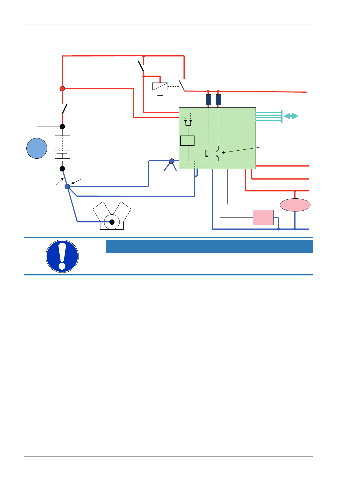
1 | Onboard Network Concept
G
Engine_GND
GND_Starpoint
Chassis
KL31
LS_GND_1
LS_GND_2
Main
Switch
UBAT
Star connection
(term30)
positive terminal
Electric Loads
IGN-
Switch
KL15
SENSPWR5
SENSGND
active
Sensor
ANA_IN(xx)
NTC
Sensor
ANA_IN(xy)
switched pos. terminal
Star connection
dig. sensors
(e.g. wheelspeed)
µC
As short as
possible
SENSPWR10
UBATT_FUSE
KL30
LS_SWITCH1…4
Bosch Motorsport
diagnosis connector
PC
Device
1 Onboard Network Concept
NOTICE
This schematic is not device specific, please see the section “Technical Data for the specifications of your device.
4/112 Data Logger C 70 Manual Bosch Motorsport

Communication channels | 2
2 Communication channels
CAN bus
The C 70 has two CAN buses configurable as input and output. Different baud rates are
selectable. Please note that the C 70 does not contain any CAN termination resistors. Thus
the CAN termination resistors need to be integrated into the wiring loom.
Ethernet channels
The C 70 has one 100 MBit full duplex Ethernet communication ports. The port is internally connected with an Ethernet switch. The Ethernet ports have 'cable auto crossover'
functionality.
RS232 ports
The C 70 has two RS232 serial ports. Baud rate for both ports is programmable. RS232
port 1 is reserved for online telemetry, port 2 can be used for reception of data from a
serial GPS receiver.
Vehicle diagnosis connector
The Bosch Motorsport vehicle diagnosis connector is used as a standard interface to connect the vehicle to a PC e.g. via a MSA-Box II. Loom connector: AS0-12-35SN
Pin Name Description Used for C 70
Pin 1 Terminal 30 Permanent positive +
Pin 2 Terminal 15 Switched positive +
Pin 3 Terminal 31 GND +
Pin 4 CAN High Diagnostic CAN bus
Pin 16 CAN Low Diagnostic CAN bus
Pin 10 K-Line ECU diagnosis
Pin 8 Ethernet RxD + Ethernet interface +
Pin 9 Ethernet RxD - Ethernet interface +
Pin 11 Ethernet TxD + Ethernet interface +
Pin 12 Ethernet TxD - Ethernet interface +
Pin 22 Screen Cable screen +
Bosch Motorsport Data Logger C 70 Manual 5/112

3 | Preparation
3 Preparation
Use the C 70 only as intended in this manual. Any maintenance or repair must be performed by authorized and qualified personnel approved by Bosch Motorsport.
Operation of the C 70 is only certified with the combinations and accessories that are specified in this manual. The use of variant combinations, accessories, and other devices outside the scope of this manual are only permitted when they have been determined to be
compliant from a performance and safety standpoint by a representative from Bosch
Motorsport.
Read the manual carefully and follow the application hints step by step. Do not hesitate to
contact us, contact data can be found on the last page of this document.
Important information on Electromagnetic Conformity
To avoid unwanted interference with the environment (people, animals, electronic devices)
or unwanted harm to the environment, it is mandatory that the user of the C 70 carries
out an appropriate analysis to determine the electromagnetic interaction the C 70 may
have with its individual installation environment.
Disclaimer
Due to continuous enhancements, we reserve the rights to change any illustrations, photos and technical data within this manual.
Please retain this manual for your records.
NOTICE
In this document, all screenshots are created by way of example for a
display. Please consider this and replace the product names with the
name of your device.
6/112 Data Logger C 70 Manual Bosch Motorsport

4 Power Supply
Please ensure that you have a good ground installation. That means:
– A ground that has a solid, low resistance connection to the negative battery terminal
– Connection should be free from dirt, grease, paint, anodizing, etc.
– Use large diameter wire
– More metal-to-metal contact is better!
The following notations for power signals are used:
– KL 15 is a switched battery rail controlled by the IGN-switch
– KL 30 is an unswitched battery positive rail (same as battery positive terminal)
– KL 31 is an unswitched ground rail (same as battery negative terminal)
Be careful to observe current limits of wires and connector pins!
Power Supply | 4
Bosch Motorsport Data Logger C 70 Manual 7/112
5 | Analog and Frequency Inputs
5 Analog and Frequency Inputs
Analog inputs
– 0 to 5 V
– 12 bit A/D converter
– Switchable 3.01 kOhm pull-up resistor
– 10 kHz acquisition rate, up to 1 kHz recording rate
– Linear phase digital filter
Frequency inputs
– 5 V Hall-effect type, 2.5 V trigger level (DF11 input with current interface or 5VHall-
effect input with 2.5 V trigger level)
– 20 kHz max. frequency
– 10 ms measurement window
5.1 Analog inputs
5.1.1 Measurements channels
For each analog channel, several ‘subchannels’ are available.
Measurement labels with the characters ‘raw’ show the exact values in mV.
Measurement labels with the characters ‘_fi’ show filtered values.
The word ‘name’ in the table is a placeholder for the channel’s name.
Measurement label Function
raw_name mV value of sensor
raw_name_fi Filtered mV value of sensor
name Physical value of sensor
name_fi Filtered physical value
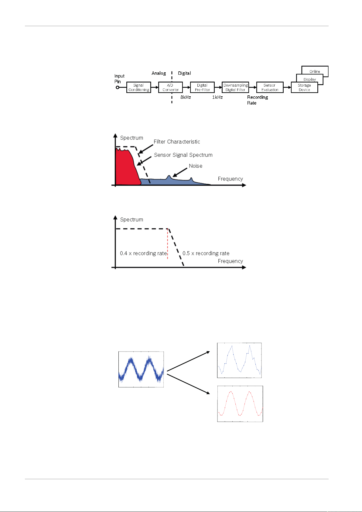
Filtered channels are routed through digital low pass filters:
– C 70 uses A/D converter oversampling and digital filtering to recording rate
– Digital filters eliminate ‘out-of-band’ noise
– Cut-off frequency automatically adjusted to recording rate
– Linear phase – no signal distortion
– Latency compensation – no filter delay in recorded data
8/112 Data Logger C 70 Manual Bosch Motorsport
Analog and Frequency Inputs | 5
Drag + Drop
5.2 Configuring inputs
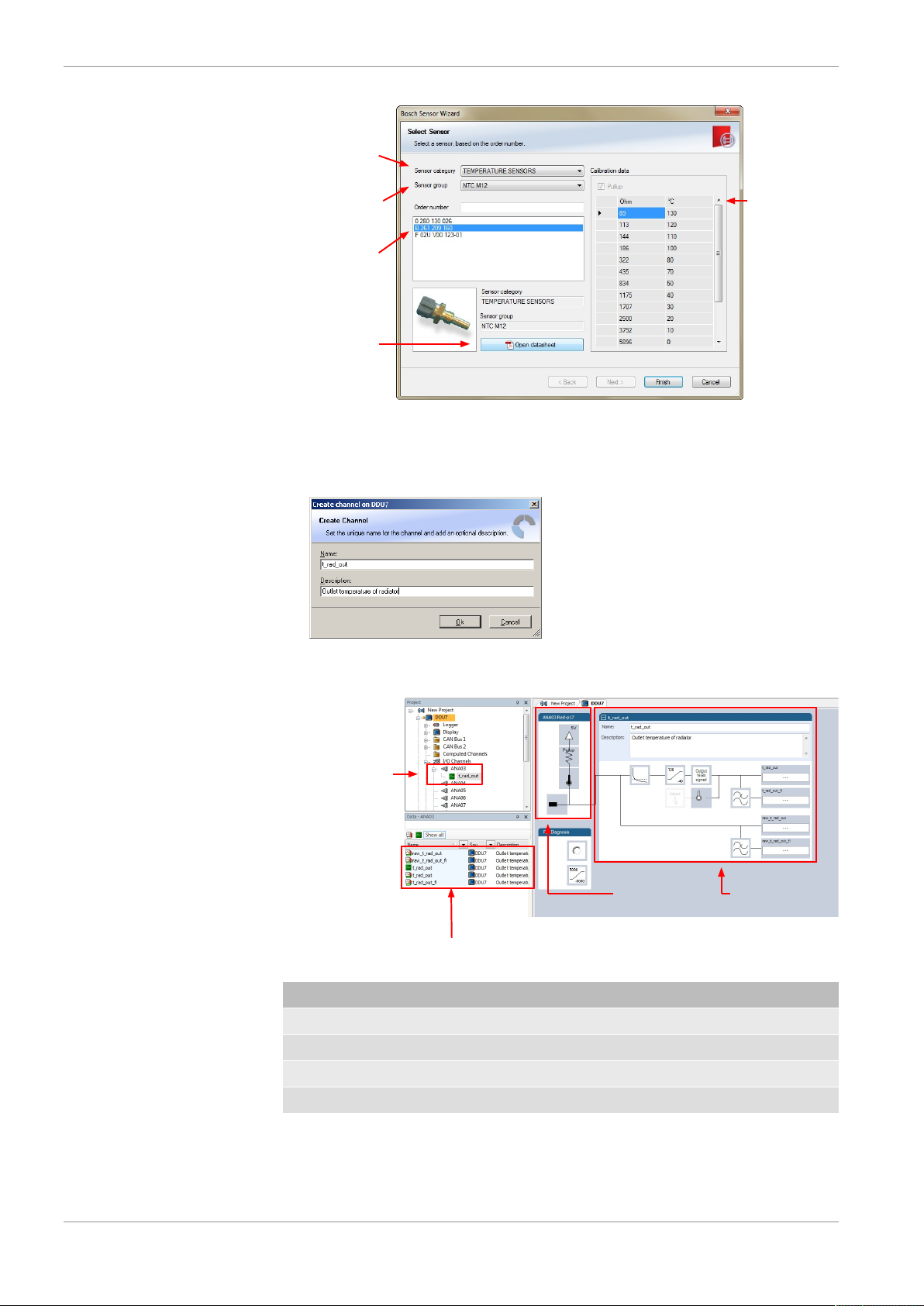
5.2.1 Configuring a predefined Bosch sensor with the 'Bosch Sensor Wizard'
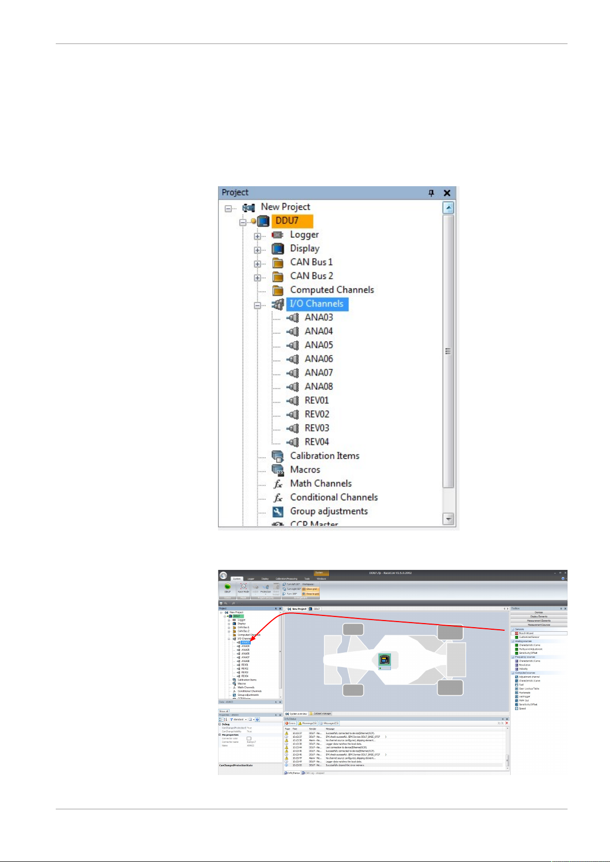
1. Click on ‘Measurement Sources’ in the Toolbox.
2. To expand the list of ‘I/O Channels’, click on ‘+’ in the C 70 Project Tree.
3. Drag the “Bosch Sensor Wizard” from the Toolbox and drop it on the desired analog
input channel in the C 70 Project Tree.
The “Bosch Sensor Wizard” opens.
Bosch Motorsport Data Logger C 70 Manual 9/112
5 | Analog and Frequency Inputs
1st: Choose the
sensor´s category
2nd: To narrow your
choice, choose a
type
3rd: Select the
exact type
Opens sensor´s
datasheet
These calibration
values will be used
Channel is linked
to ANA03
Input pin Pull-up
resistor is activated
Calculation of
physical value with
characteristic curve
4. Click ‘Finish’ when done.
The “Create channel” window opens.
5. Enter the channel name and description.
6. Click ‘Ok’ when done.
The channel is inserted into the C 70 Project Tree.
Available measurements for channel:
Measurement label Function
raw_name mV value of sensor
raw_name_fi Filtered mV value of sensor
name Physical value of sensor
name_fi Filtered physical value
10/112 Data Logger C 70 Manual Bosch Motorsport
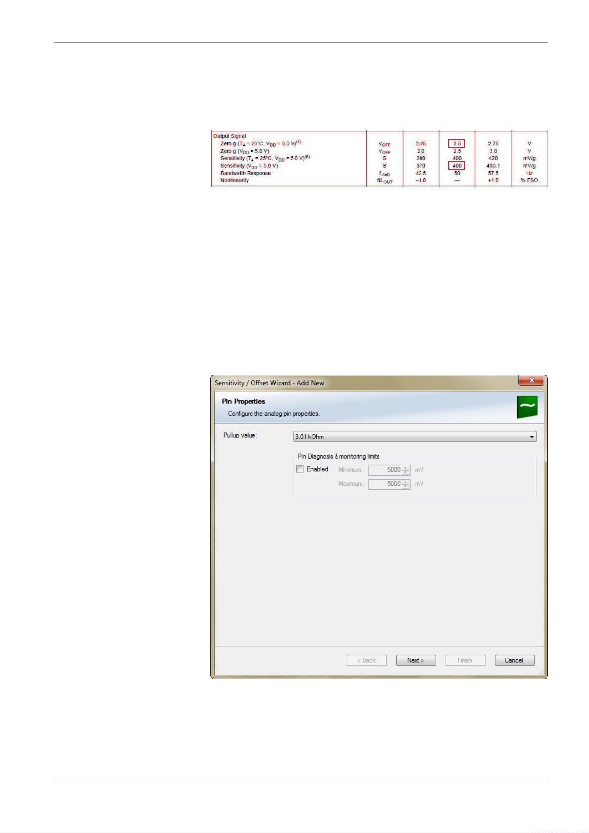
5.2.2 Configuring a generic linear sensor
Example: Acceleration sensor 5 g
– From sensor data sheet - operating characteristics:
– Sensitivity 400 mV/g, Offset 2,500 mV
– The sensor has a linear output signal with sensitivity and offset
1. Click on ‘Measurement Sources’ in the Toolbox.
2. To expand the list of ‘I/O Channels’, click on ‘+’ in the C 70 Project Tree.
3. Drag the “Sensitivity/Offset” analog signal source from the Toolbox and drop it on the
desired analog input channel in the C 70 Project Tree. A “Sensitivity/Offset Wizard”
opens.
Analog and Frequency Inputs | 5
4. To activate the internal pullup-resistor, check the box. The internal pullup-resistor is
used to get a 5 V signal at the analog channel of the C 70. It allows you to use a pushbutton. The fixed value of the internal pullup-resistor is 3,010 Ohm. If using an additional external pullup-resistor, set up the overall resistance.
5. Click ‘Next’ when done.
The second part of the “Sensitivity/Offset Wizard” opens.
Bosch Motorsport Data Logger C 70 Manual 11/112
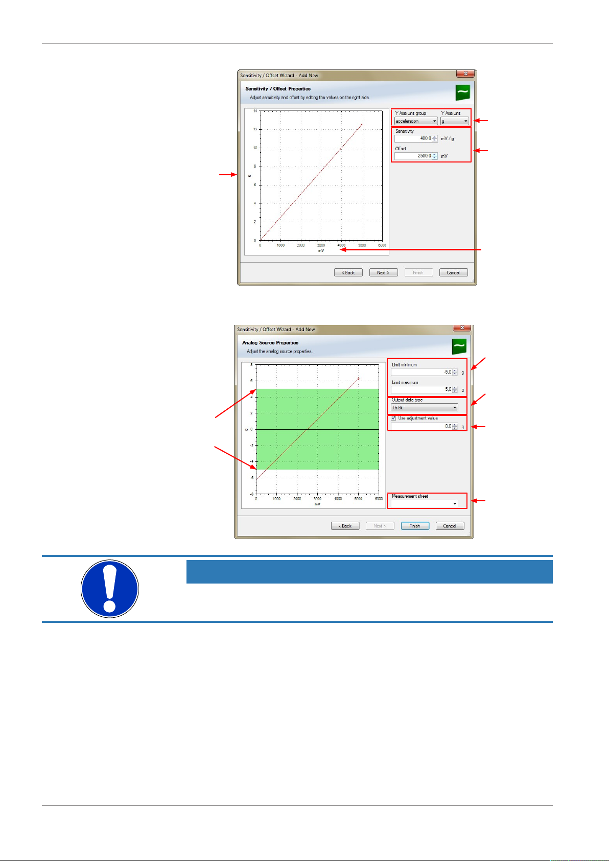
5 | Analog and Frequency Inputs
Physical
(channel)
value
Choose unit
group and unit of
physical value
Enter values from
sensor datasheet
Electrical (pin) value
Physical limits
of channel
Enter physical
limits of the sensor
Choose data type
of the measurement
variable
Check box to enable
online calibration of
offset and enter
desired physical
offset value
Enter name to
automatically create
a new measurement
sheet
6. Click ‘Next’ when done.
The third part of the “Sensitivity/Offset Wizard” opens.
NOTICE
Working with automatically created measurement sheets is explained in chapter ‘Setting up an online measurement [}28]’.
7. Click ‘Finish’ when done.
8. Enter a channel name and a description.
9. Click ‘OK’ when done.
The channel is inserted into the C 70 Project Tree.
12/112 Data Logger C 70 Manual Bosch Motorsport
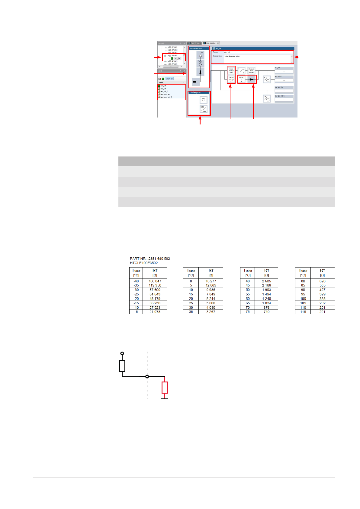
Analog and Frequency Inputs | 5
Input pin Pull-up
resistor is
activated
Sensivity and
Offset value
for sensor
Adjustment
is enabled
Channel is linked
to ANA04
Pin Diagnosis
Name and
Description
editable
Pin
Thermistor
+5V
3 kOhm
Available measurements for channel:
Measurement label Function
raw_name mV value of sensor
raw_name_fi filtered mV value of sensor
name physical value of sensor
name_fi filtered physical value
5.2.3 Configuring a generic nonlinear sensor
Example: Thermistor 5 kOhm
– From sensor data sheet - resistance values over temperature:
– The sensor has a nonlinear behavior
– Use characteristic curve for linearization
– Input voltage is the ratio between pull-up resistor and thermistor
1. Click ‘Measurement Sources’ in the Toolbox.
2. To expand the list of ‘I/O Channels’, click on ‘+’ in the C 70 Project Tree.
3. Drag the “Characteristic Curve” analogue signal source from the Toolbox and drop it
on the desired analogue input channel in the C 70 Project Tree.
Bosch Motorsport Data Logger C 70 Manual 13/112
5 | Analog and Frequency Inputs
Drag + Drop
A “Characteristic Curve Wizard” opens.
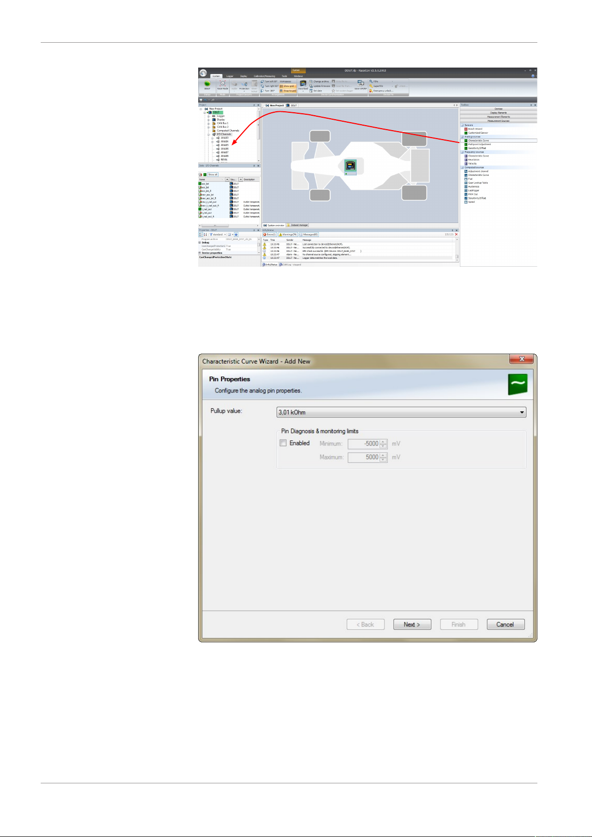
4. To activate the internal pull up-resistor, check the box. The C 70 pull up-resistor is
used to get a 5 V signal at the analogue channel of the C 70. It allows you, to use a
push-button. The fixed value of the internal pull up-resistor is 3,010 Ohm. If using an
additional external pull up-resistor, set up the overall resistance.
5. Click ‘Next’ when done.
The second part of the “Sensitivity/Offset Wizard” opens.
14/112 Data Logger C 70 Manual Bosch Motorsport
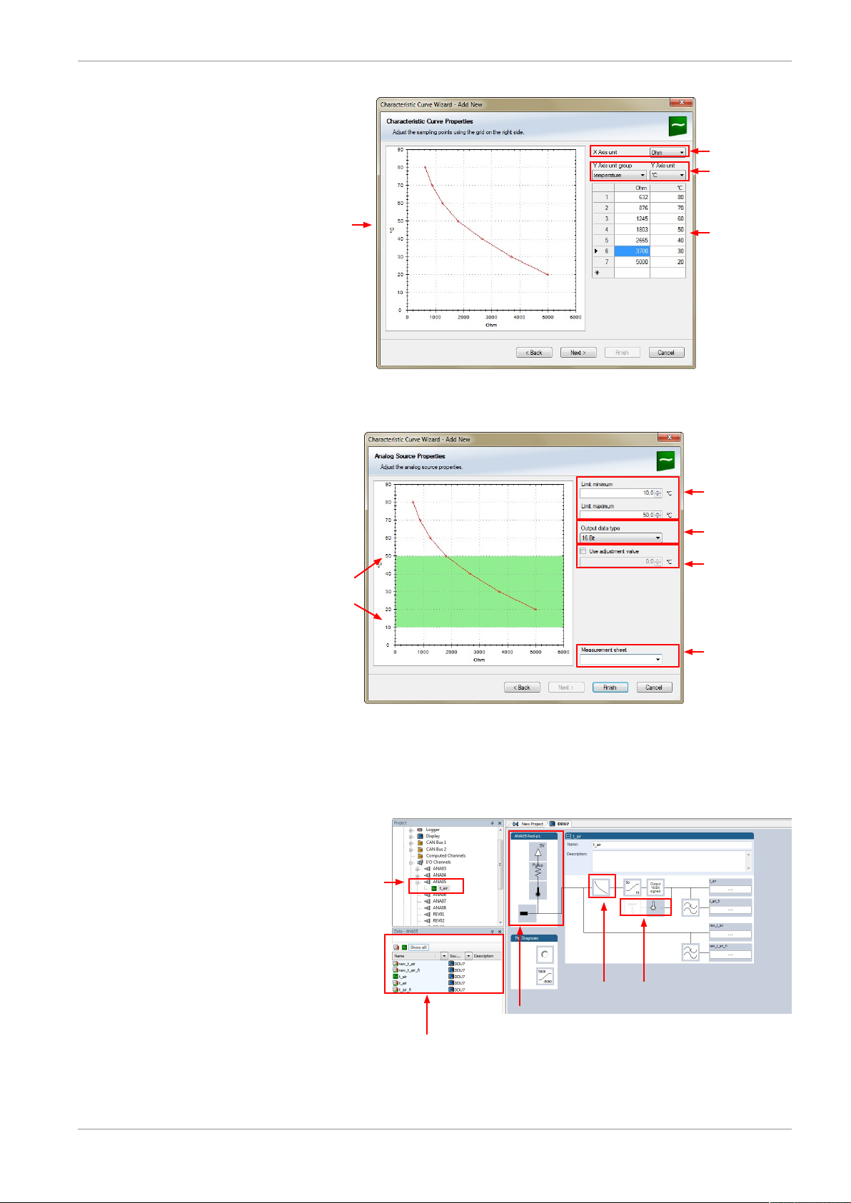
Physical
(channel)
value
Choose 'Ohm' to
enter datasheet
values directly.
Select physical
unit.
Enter resistance/
temperature pairs
from sensor datasheet here (the
3.01 kOhm pullupresistor is automatically taken
into account)
6. Click ‘Next’ when done.
Physical
limits of
channel
Enter physical limits
of the channel
Choose data type of
the measurement
variable
This sensor does not
need offset
calibration
Enter name to automatically create a
new measurement
sheet
Channel is linked
to ANA05
Input pin Pull-up
resistor is activated
Characteristic
curve for sensor
Adjustment
is disabled
The third part of the “Characteristic Curve Wizard” opens.
Analog and Frequency Inputs | 5
7. Click ‘Finish’ when done.
8. Enter channel name and description.
9. Click ‘OK’ when done.
The channel is inserted into the C 70 Project Tree.
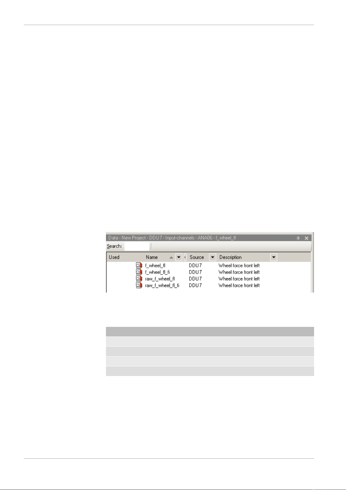
Available measurements for channel:
Bosch Motorsport Data Logger C 70 Manual 15/112
5 | Analog and Frequency Inputs
5.2.4 Configuring a multipoint adjustment
Measurement label Function
raw_name mV value of sensor
raw_name_fi filtered mV value of sensor
name physical value of sensor
name_fi filtered physical value
NOTICE
Working with automatically created measurement sheets is explained in chapter ‘Setting up an online measurement [}28]’.
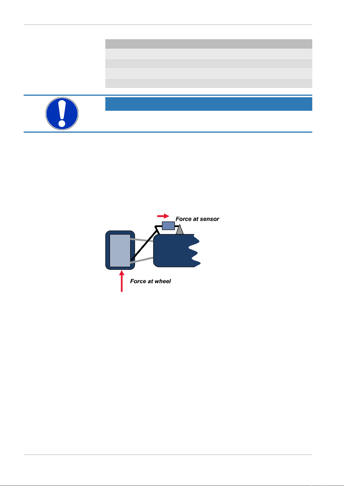
Example: Measurement of wheel force
– Physical property ‘wheel force’ not directly measureable
– Load transfer through suspension kinematics
– Physical value at sensor position defined by vehicle
– Curve definition by online adjustment at vehicle
1. Click on ‘Measurement Sources’ in the Toolbox.
2. Expand the list of ‘I/O Channels’ by clicking on ‘+’ in the C 70 Project Tree.
3. Drag the ‘Multipoint Adjustment’ analog signal source from the Toolbox and drop it
on the desired analog input channel in C 70 Project Tree.
16/112 Data Logger C 70 Manual Bosch Motorsport

Analog and Frequency Inputs | 5
Drag + Drop
A ‘Multipoint Adjustment Wizard’ opens.
4. To activate the internal pullup-resistor, check the box. The internal pullup-resistor is
used to get a 5 V signal at the analog channel of the C 70. It allows you to use a pushbutton. The fixed value of the internal pullup-resistor is 3.01 kOhm. If using an additional external pullup-resistor, set up the overall resistance.
5. Click ‘Next’ when done.
Bosch Motorsport Data Logger C 70 Manual 17/112
The second part of the ‘Multipoint Adjustment Wizard’ opens.
5 | Analog and Frequency Inputs
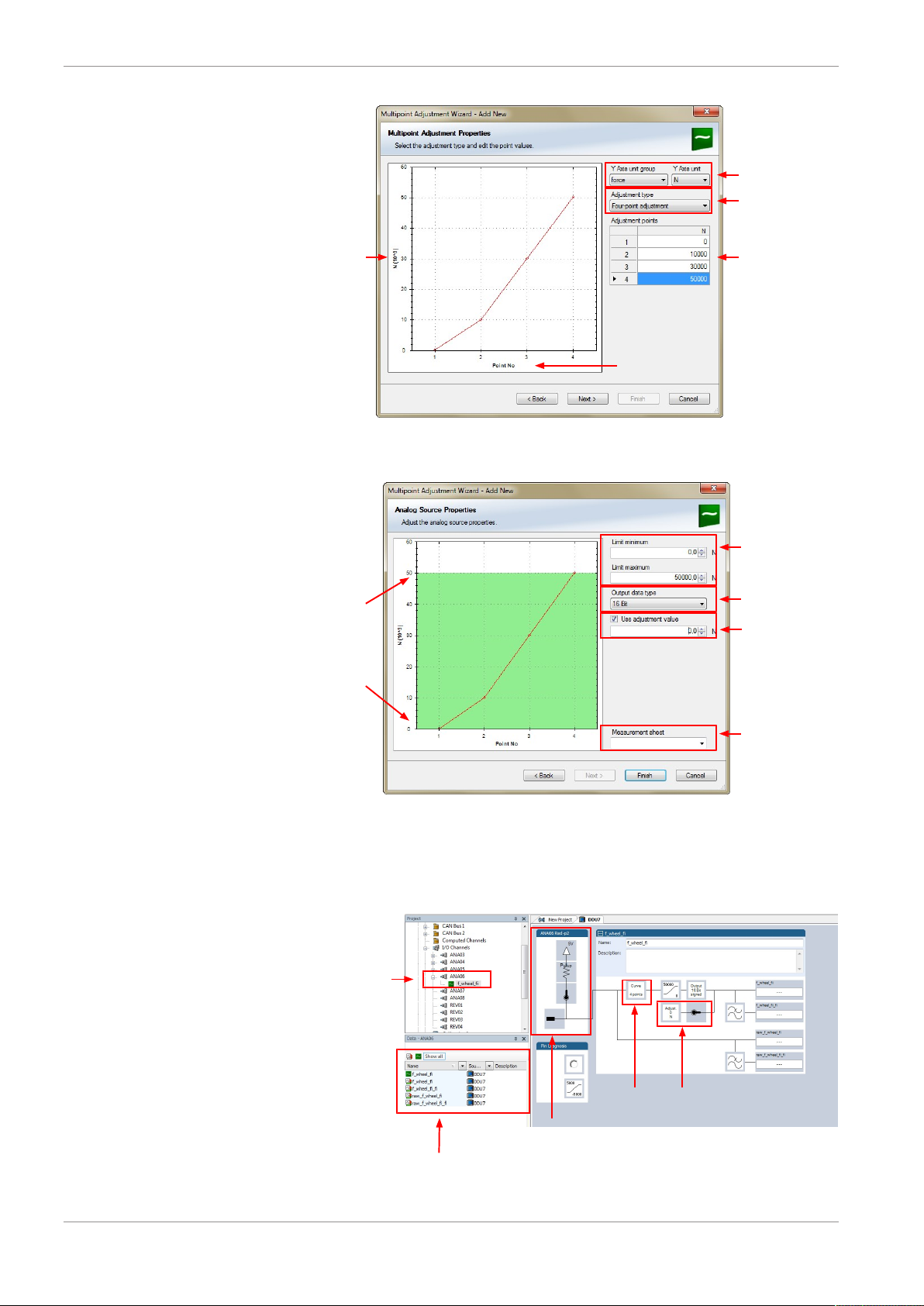
Physical
(channel)
value
Choose unit group
and unit of physical
value
Select type of curve
Enter physical
adjustment values
her (can still be
edited later)
Electrical (pin) value
Physical limits
of channel
Enter physical limits
of the sensor
Choose data type
of the measurement
variable
Enable additional
online calibration
Enter name to automatically create a
new measurement
sheet
Channel is linked
to ANA06
Input pull-up resistor
is deactivated
Characteristic
curve for sensor
Adjustment
is enabled
6. Click ‘Next’ when done.
The third part of the ‘Multipoint Adjustment Wizard’ opens.
18/112 Data Logger C 70 Manual Bosch Motorsport
7. Click ‘Finish’ when done.
8. Enter channel name and description.
9. Click ‘OK’ when done.
The channel is inserted into the C 70 Project Tree.
Available measurements for channel:

Analog and Frequency Inputs | 5
Measurement label Function
raw_name mV value of sensor
raw_name_fi filtered mV value of sensor
name physical value of sensor
name_fi filtered physical value
Online definition of the curve is covered in the chapter ‘Online calibration of measurement
channels [}33]’ of this manual.
NOTICE
Working with automatically created measurement sheets is explained in chapter ‘Setting up an online measurement [}28]’.
Bosch Motorsport Data Logger C 70 Manual 19/112
5 | Analog and Frequency Inputs
0 500 1000 1500 2000 2500 3000
-2
-1.5
-1
-0.5
0
0.5
1
1.5
2
Abtastwerte (roh)
Wert
10000Hz Abtastrate
0 5 10 15 20 25 30
-1.5
-1
-0.5
0
0.5
1
1.5
Abtastwerte (gefiltert)
Wert
100Hz Abtastrate
0 5 10 15 20 25 30
-1.5
-1
-0.5
0
0.5
1
1.5
Abtastwerte (dezimiert)
Wert
100Hz Abtastrate
Sensor signal with noise
Recorded signal 100Hz
(unfiltered)
Recorded signal 100Hz
(filtered)
5.2.5 Digital filter details
C 70 uses A/D converter oversampling and digital filtering to recording rate.
Digital filters eliminate ‘out-of-band’ noise
Cut-off frequency automatically adjusted to recording rate
Example:
– 100 Hz recording rate (10 ms)
– <40 Hz pass band (>99 %)
– >50 Hz stop band (<1 %)
Linear phase – no signal distortion
20/112 Data Logger C 70 Manual Bosch Motorsport
Latency compensation – no filter delay in recorded data
– Filtering is (smart) averaging over several samples
– Filtered signal is delayed with respect to real time signal
– C 70 filters have constant, frequency independent delay
Drag + Drop
– Delay (e.g. 22 samples at 10 ms) is corrected during recording
– No delay filtered vs. unfiltered in recorded data
– Correction is (of course) not possible for real time data (display, online, PWM out)
– Use filtered data for recording, use unfiltered data for real-time
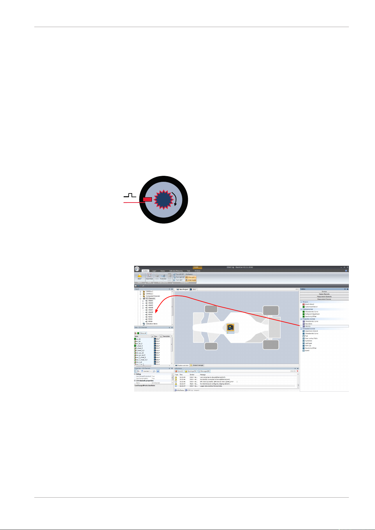
5.2.6 Configuring a frequency input
Example: measurement of wheel speed
– Pulse wheel attached to wheel
– Each passing tooth of pulse wheel triggers hall sensor
– Calculation of wheel speed with wheel circumference
Analog and Frequency Inputs | 5
1. Click on ‘Measurement Sources’ in the Toolbox.
2. To expand the list of ‘I/O Channels’, click on the ‘+’ in the C 70 Project Tree.
3. Drag the ‘Velocity’ digital signal source from the Toolbox and drop it on the desired
‘REV’ input channel in the C 70 Project Tree.
The ‘Velocity Wizard’ opens.
4. Select the sensor type. The DDU10 works with Halleffect and DF11 sensors.
Bosch Motorsport Data Logger C 70 Manual 21/112
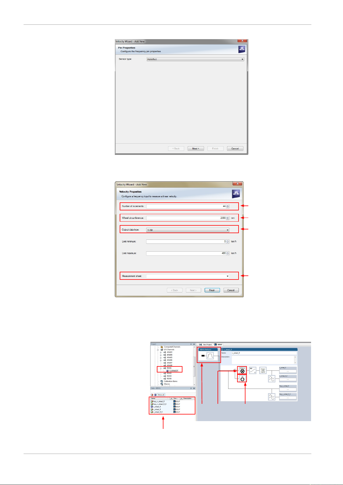
5 | Analog and Frequency Inputs
Number of teeth on the
pulse wheel
Circumference of wheel
for speed calculation
Choose data type of the
measurement variable
Enter name to automatically
create a new measurement sheet
Channel is linked
to REV01
Input pin
has hall
interface
Number of
teeth
Wheel
circumference
5. Click ‘Next’.
6. Define the settings for the sensor.
22/112 Data Logger C 70 Manual Bosch Motorsport
7. Click ‘Finish’ when done.
8. Enter the channel name and description.
9. Click ‘OK’ when done.
The channel is inserted into the C 70 Project Tree.
Available measurements for channel:
Measurement label Function
Drag + Drop
raw_name mV value of sensor
raw_name_fi filtered mV value of sensor
name physical value of sensor
name_fi filtered physical value
NOTICE
Measurement of ‘Revolution’ is similar.
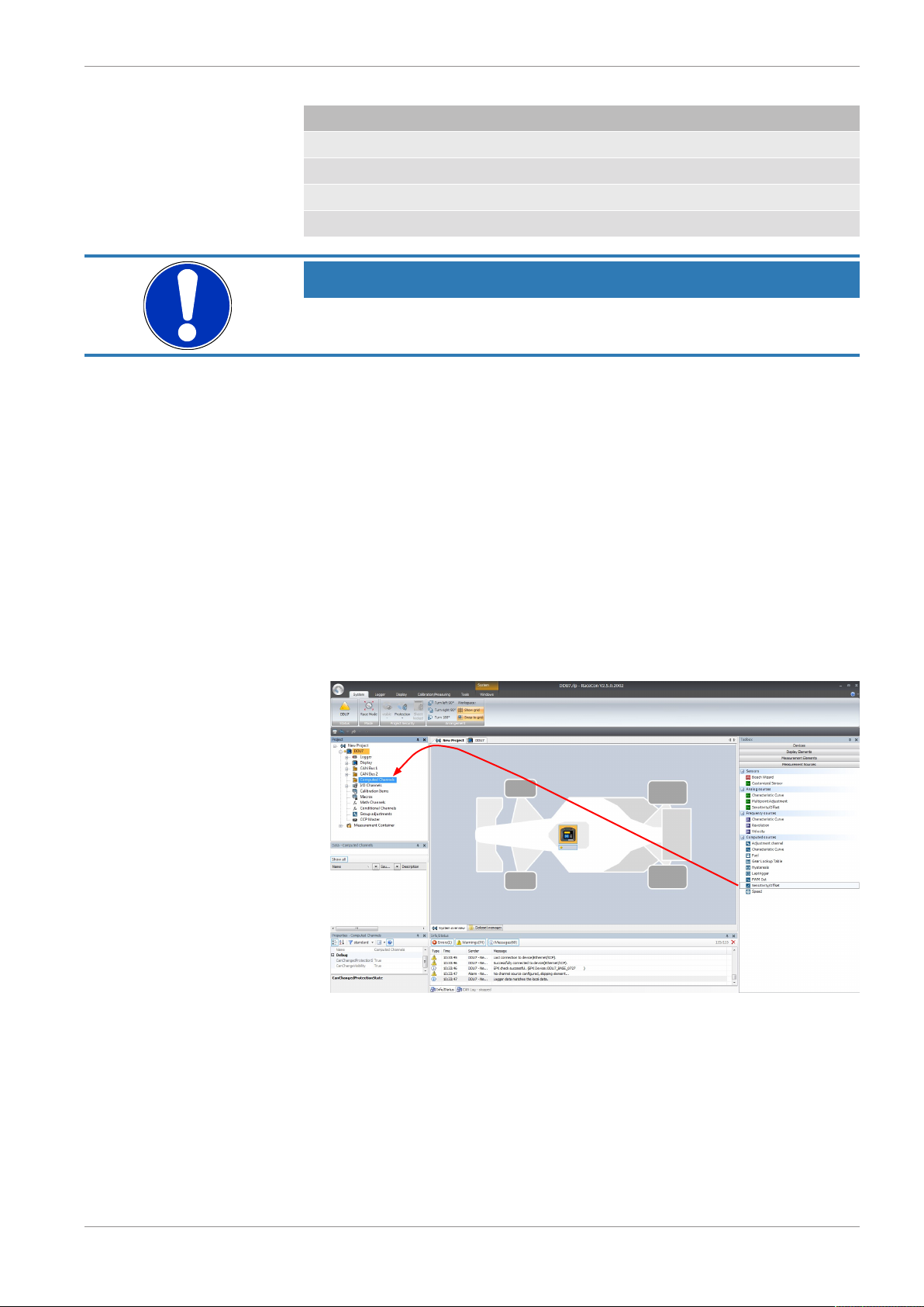
5.3 Configuring computed sources
Computed sources receive data from a measurement channel rather than an input pin.
– Sensitivity/Offset calculation on input channel
– Characteristic curve calculation on input channel
Analog and Frequency Inputs | 5
– Computed vehicle speed
– Lap trigger (covered in a special separate section)
Example: Sensitivity/offset calculation on input channel
1. Click ‘Measurement Sources’ in the Toolbox.
2. Drag the ‘Sensitivity/Offset’ computed source from the Toolbox and drop it on ‘Computed Channels’ in the C 70 Project Tree.
A ‘Computed Sensitivity/Offset Wizard’ opens.
Bosch Motorsport Data Logger C 70 Manual 23/112
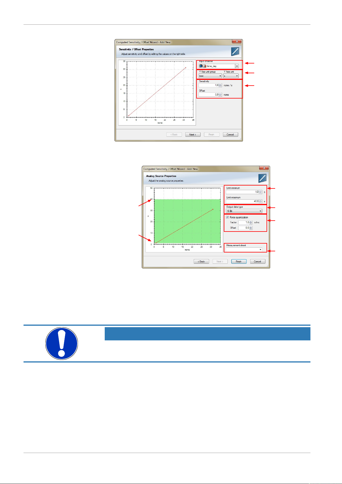
5 | Analog and Frequency Inputs
Choose input channel
Choose unit group and
unit of output
Enter sensivity and offset
of conversion formula
Physical limits
of channel
Enter physical limits
of the channel
Choose data type of
the measurement
variable
Check the box to
force the channel's
quantization if the
quantization should
be a fixed value in
the whole CAN
system.
Enter name to automatically create a
new measurement
sheet.
3. Click ‘Next’ when done.
The second part of the ‘Computed Sensitivity/Offset Wizard’ opens.
4. Click ‘Finish’ when done.
5. Enter channel name and description.
6. Click ‘OK’ when done.
The channel is inserted into the C 70 Project Tree.
NOTICE
Working with automatically created measurement sheets is explained in chapter ‘Setting up an online measurement’.
5.4 Hysteresis
The hysteresis function avoids the high-frequent switchover of the measurement channel
value. The hysteresis can be adjusted for each input measurement channel individually
and can be used for further processing.
1. Click ‘Measurement Sources’ in the Toolbox.
2. Drag the ‘Hysteresis’ computed source from the Toolbox and drop it on ‘Computed
Channels’ in the C 70 Project Tree.
A ‘Hysteresis Wizard’ opens.
24/112 Data Logger C 70 Manual Bosch Motorsport
Analog and Frequency Inputs | 5
a)
b)
c)
d)
e)
f)
g)
h)
i)
j)
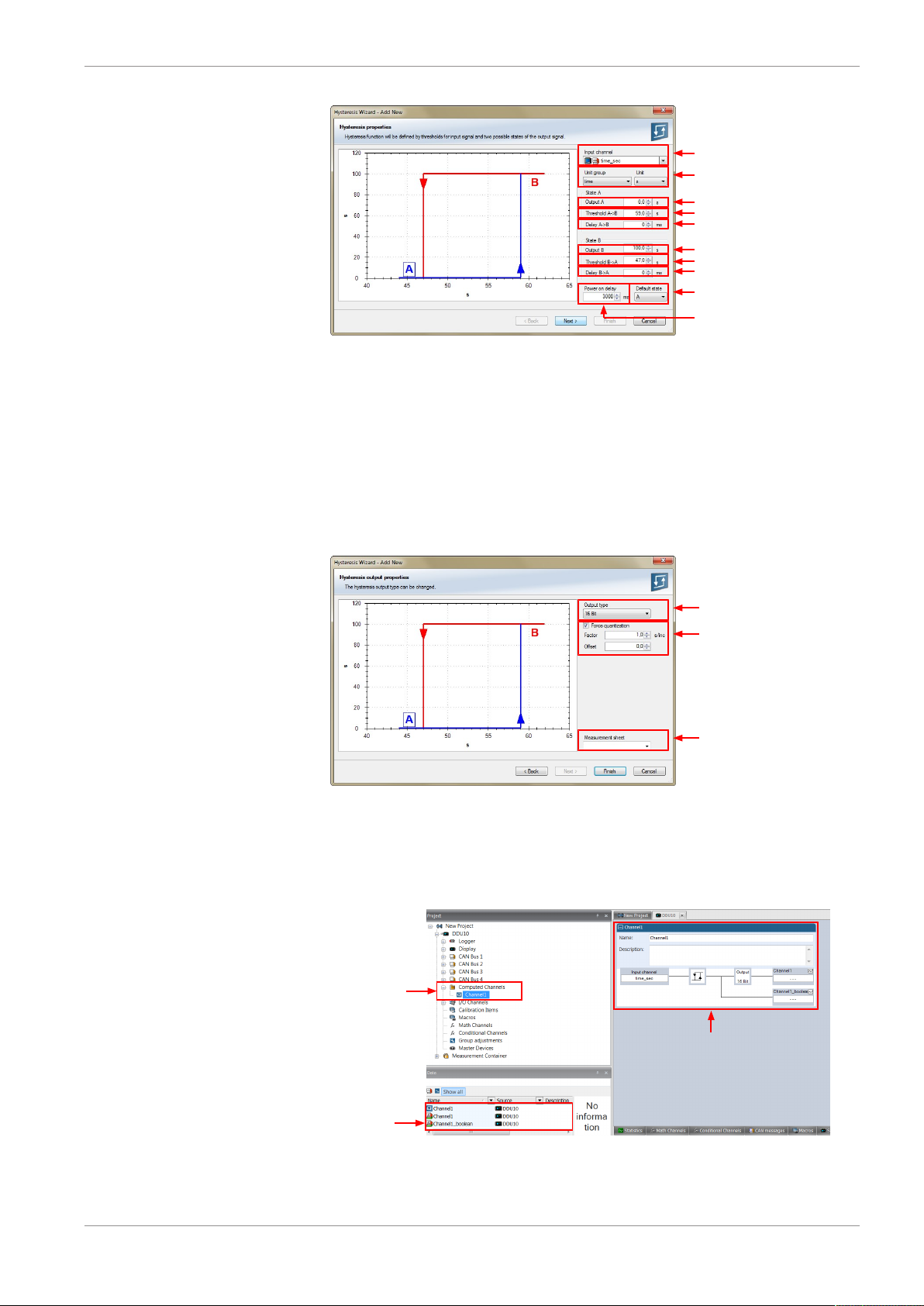
a) Choose input measurement channel.
b) Choose unit group and unit of output.
c) Enter output value of state A in the unit selected in b).
d) Enter threshold value when state changes from A to B.
e) Enter delay time when state changes from A to B.
f) Enter output value of state B in the unit selected in b).
g) Enter threshold value when state changes from B to A.
h) Enter delay time when state changes from B to A.
i) Enter time when the hysteresis function is activated after vehicle´s startup.
j) Enter the channel´s state (A or B) at startup.
Choose data type of
the measurement variable
Check the box to force the
channel's quantization if the
quantization should be a fixed
value in the whole CAN system
Enter name to automatically
create a new measurement sheet
Channels available
in Computed sources
Available
measurements
for channel
Calculation of hysteresis
channel
3. Click ‘Next’ when done.
The second part of the ‘Hysteresis Wizard’ opens.
4. Click ‘Finish’ when done.
5. Enter channel name and description.
6. Click ‘OK’ when done.
The channel is inserted into the C 70 Project Tree.
Bosch Motorsport Data Logger C 70 Manual 25/112
5 | Analog and Frequency Inputs
Drag + Drop
5.4.1 Special functionality: Vehicle speed
This functionality allows:
– high performance vehicle owners to measure wheel spin under acceleration and
wheel slip/lock under braking.
– calculating vehicle ‘speed over ground’.
Vehicle speed calculation function
– Calculating vehicle speed of 2 wheel drive: (Wheel speeds of non-driven axle as input)
Calculated speed is average of both speeds if speed difference between wheels <
limit.
Calculated speed is maximum of both speeds if speed difference between wheels >
limit.
– Calculating vehicle speed of 4 wheel drive: (Wheel speeds of all wheels as input)
Calculated speed is speed of 2nd fastest wheel.
5.4.2 Setting up calculated speed
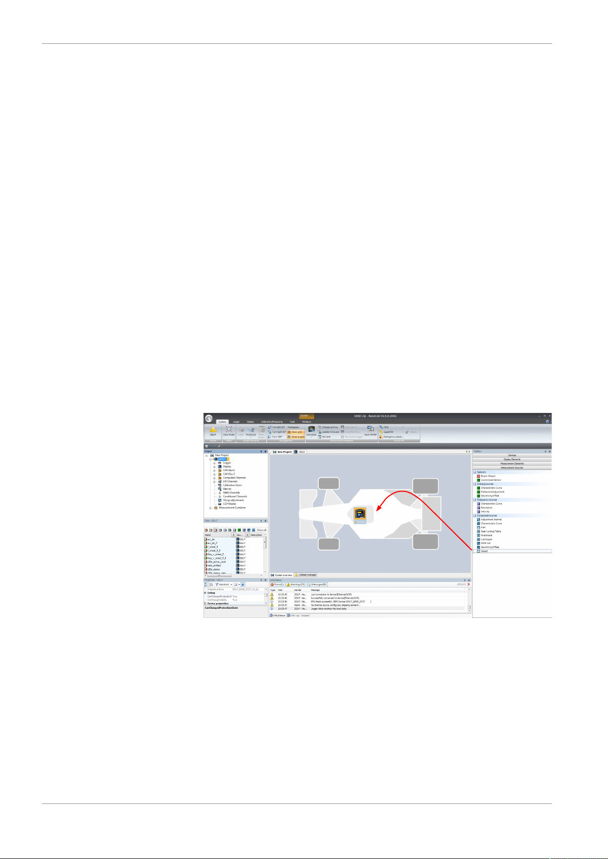
1. Click on tab ‘System Overview’.
2. Click on ‘Measurement Sources’ in the Toolbox.
3. Drag the ‘Speed’ computed source from the Toolbox and drop it on the project name
in the C 70 Project Tree. Do not drop it on ‘C 70’!
A ‘Calculated Speed Wizard’ opens.
26/112 Data Logger C 70 Manual Bosch Motorsport
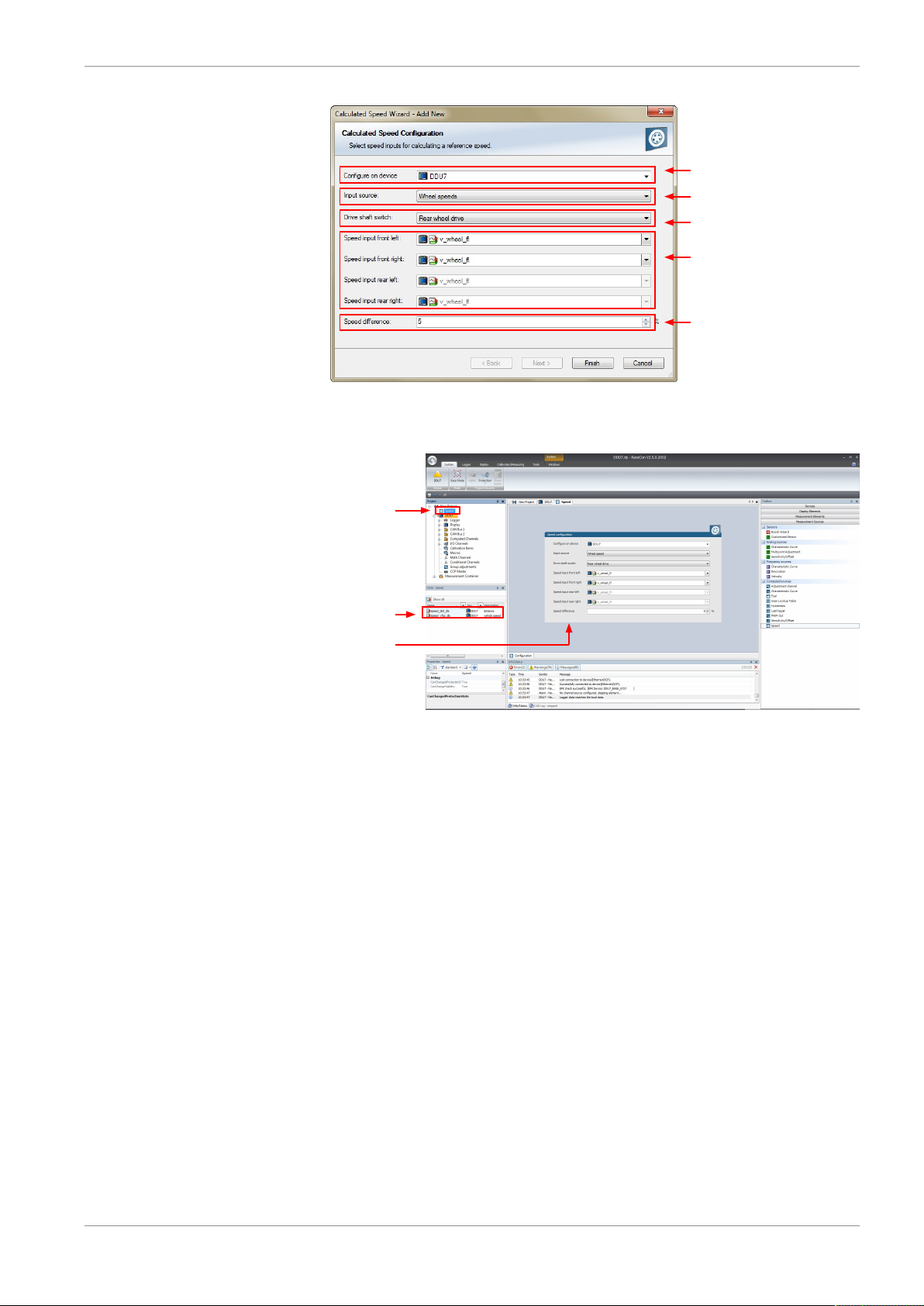
Choose device
Choose input source
(internal/external)
Choose driven axle
Choose individual wheel
speed channels
Set limit for speed
difference for calculation
4. Click ‘Finish’ when done.
Speed calculation
in DDU Project
Tree
Measurement
channels
calculated speed
and calculated
distance
Configuration
window
The speed calculation is inserted into the C 70 Project Tree.
Analog and Frequency Inputs | 5
Bosch Motorsport Data Logger C 70 Manual 27/112
6 | Online Measurement
RaceCon changes
automatically
to "Calibration/
Measuring"
6 Online Measurement
C 70 configuration
– System configuration (channel + display configuration, CAN I/O, etc.) is stored in the
C 70
– Use RaceCon to create and download configuration from the PC to C 70 Communica-
tion interface: Ethernet
– Communication protocol: XCP
Online measurement + calibration
– System status and diagnosis
– Check and calibrate sensors in the vehicle
– Live display of sensor values on the PC
– Use RaceCon for diagnosis, online measurement and calibration
– Communication interface: Ethernet
– Communication protocol: XCP
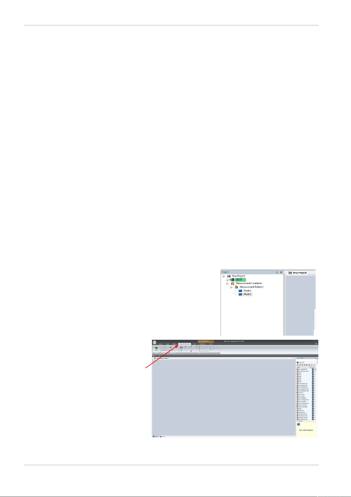
6.1 Setting up an online measurement
C 70 supports online measurement of sensor values and diagnostic variables.
1. Expand ‘Measurement Container’ and ‘Measurement Folder 1’ in the Project Tree and
double-click on ‘Sheet1’. Alternatively, click on the ‘Calibration/Measuring’ tab to
open the window directly.
‘Sheet 1’ opens in a new ‘Calibration/Measuring’ window.
28/112 Data Logger C 70 Manual Bosch Motorsport
2. Click on the ‘Folder/Sheets’ tab, which appears when you are in the ‘Calibration/
Measurement’ window, to create a new measurement folder.
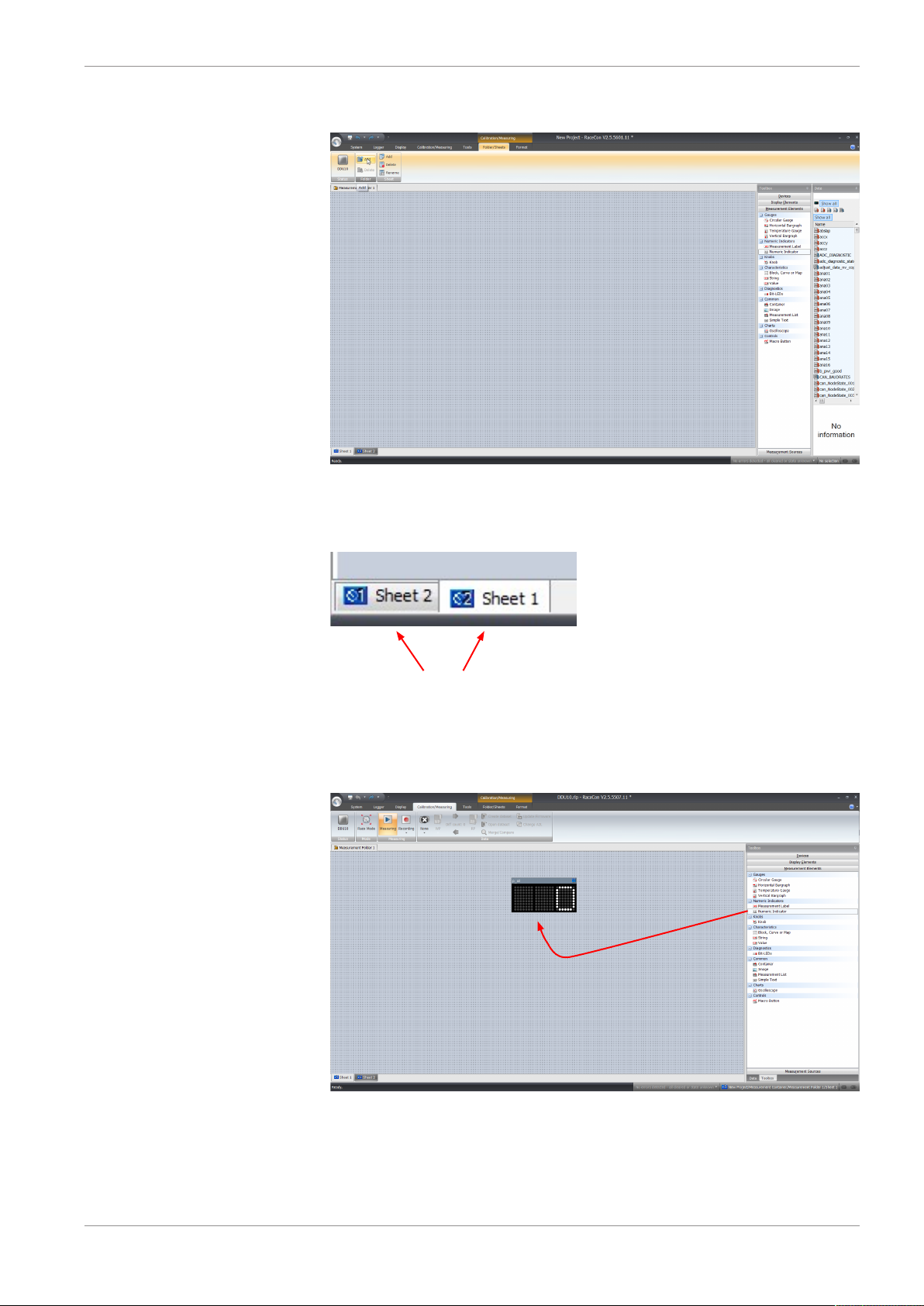
Online Measurement | 6
Tabs to switch between sheets
Drag + Drop
3. Click on the ‘Add’ button for folders in the upper left corner.
In the menu for sheets, you will find buttons to add, delete and rename new sheets
4. To change between different sheets, click on the tabs on the bottom of the ‘Calibration/Measuring’ window.
To add an element to a measurement sheet, perform the following steps:
5. Drag a measurement element from the Toolbox and drop it on the measurement
sheet.
Bosch Motorsport Data Logger C 70 Manual 29/112
6. Select the desired measurement channel from the ‘Data’ area and drop it on the
measurement element.
If the C 70 shows the green status, the value is displayed.
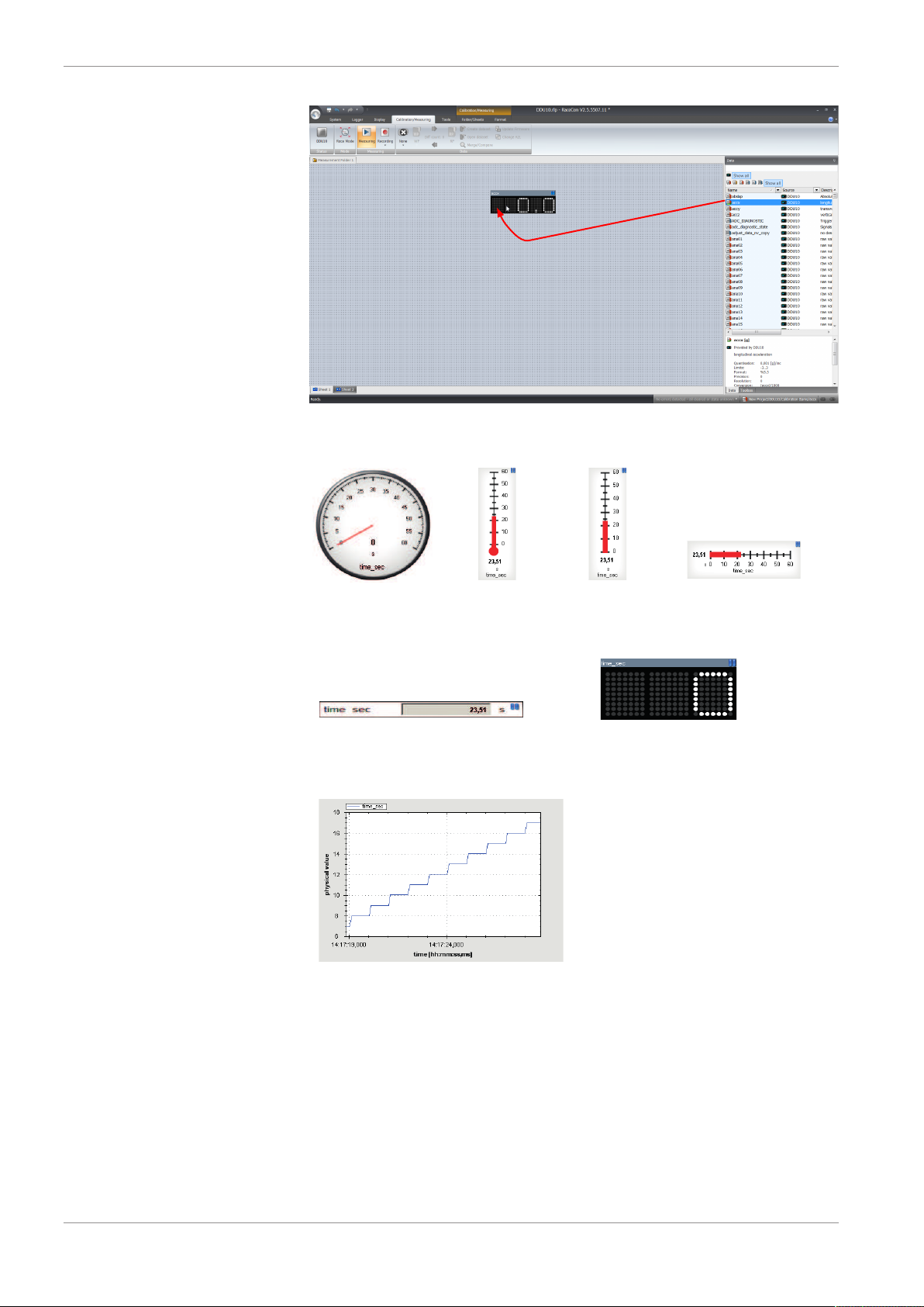
6 | Online Measurement
Drag + Drop
Vertical Bar
graph style
Temperature
gauge
Horizontal Bar
graph style
Circular gauge
Numeric indicator
Measurement label
Oscilloscope (Chart)
RaceCon offers different types of measurement elements:
30/112 Data Logger C 70 Manual Bosch Motorsport
6.1.1 Automatic creation of measurement sheets
RaceCon can create measurement sheets automatically.
You can create and use measurement sheets with the C 70 as well as with all other devices
connected to RaceCon.
 Loading...