

Bosch BEA 150, BEA 250, BEA 350 Repair Instructions

Repair Instructions
Bosch Emissions Analysis
BEA 150
BEA 250
BEA 350
In conjunction with Service
software for PC
1

Contents: Page
Contents: Page
1. Important information 4
1.1 Compulsory calibration 4
2. Testing equipment and settings for the
Service software 5
2.1 Testing equipment 5
2.2 Calibrating gases (with manufacturer's certicate) 5
2.3 Settings for the Service software 6
2.3.1 Setting the interface for the Service program 6
2.3.2 Service Software Language Selection 6
2.3.3 Language Selection for RTM 430
Smoke Opacity Module Service Software 7
3. Brief description of unit functions and
Servicing the unit 8
3.1 Exhaust-gas analyzer module 8
3.1.1 Analyzer part (HC, CO and CO2 measurement) 8
3.1.2 System calibration 8
3.1.3 Self-test 8
3.1.4 Adjustment (HC, CO and CO2 measuring channels) 8
3.1.5 O2 measuring channel 8
3.1.6 Compensation of pressure inuence 8
3.1.7 Compensation of temperature inuence 8
3.1.8 Measurement of excess-air factor (lambda) 8
3.1.9 Corrected CO concentration (CO
3.1.10 Parameterization 9
3.1.11 Filtration 9
3.1.12 Principle of ltration 9
3.2 Servicing the unit 9
3.2.1 Half-yearly service 9
3.2.2 Yearly service 9
) 9
vrai
4. Checking the AMM exhaust-gas analyzer
module 11
4.1 Read operating mode 12
4.2 Leakage test 12
4.3 Read measurement values 13
4.4 Read parameters 13
4.5 Write parameters 13
4.5.1 Country-specic settings 14
4.5.2 Lambda calculation On 15
4.5.3 Lambda calculation O 15
4.5.4 CO
4.5.5 CO
4.5.6 O2 sensor available 16
4.5.7 O2 sensor not available 16
4.5.8 Entering lambda coecients OCV and HCV 16
4.6 Identication 17
4.7 Test functions 17
4.7.1 Pump On 18
4.7.2 Pump O 18
4.7.3 Install new O2 sensor 18
4.7.4 O2 measurement 18
4.7.5 Readjustment with test gas 19
4.7.6 Analysis mode 21
4.7.7 Barometric sensor 21
4.7.8 Maintenance (service date) 22
4.8 Read adjustment data 22
4.9 Adjustment functions 23
4.10 Reset 23
4.11 Error inquiry 23
4.12 NO-Sensor 24
calculation On 15
vrai
calculation O 15
vrai
4.12.1 Read NO-Sensor 24
4.12.2 Set NO-Sensor 24
4.12.3 NO-Measurement 25
4.12.4 Mounting a new NO-Sensor 25
4.12.5 Readjustment with test gas 28
4.12.6 Read calibration data 30
4.12.7 Calibration interval setting 30
4.12.8 Calibration sequence setting 30
4.13 Checking opacimeter RTM 430 31
5. Checking the PCB and periphery of the
BEA control module 32
5.1 Checking the interface for DTM 32
5.2 Checking the interface for RTM 33
5.3 Checking the interface for AMM 33
5.4 Checking the interface for OBD 34
5.5 Checking the interface for OBD extern
(without CAN-protocol) 34
5.5.1 Loop test 35
5.5.2 OBD error messages 36
5.6 Testing 26-pin interface for OBD external
(with CAN protocol) 37
5.7 Checking the interface for the data terminal
(not for BEA-Euro) 38
5.8 Checking the hard disk 38
5.9 Checking the Floppy disk drive 39
5.10 Checking the internal printer 39
5.11 Checking the external printer 39
5.12 Setting the date and time 40
5.13 Video RAM test 40
5.14 Display test 41
5.15 Display test geometry image 41
5.16 Display test full screen all white 41
5.17 Display test full screen all black 42
5.18 Checking the Foil keypad 42
5.19 Checking the PC keyboard 42
5.20 Checking the remote control 43
5.21 Checking the Test calibration switch for Customer
Service 43
5.22 Reading out the Error list 43
5.23 Download SystemSoft 43
6. Checking the engine-speed and
temperature measuring module (DTM) 45
6.1 Checking oil temperature and engine speed in
Diesel Diagnosis 45
6.1.1 Terminal diagram of connection cable for
clamp-on pickup 46
6.1.2 Terminal diagram of temperature sensor 46
6.2 Checking oil temperature and engine speed in
Petrol Diagnosis 47
6.2.1 Terminal diagram of inductive clip-on trigger sensor 48
6.3 Checking V-lambda 48
6.3.1 Terminal diagram of V-lambda cable 49
6.4 Checking the ignition point and dwell angle 49
6.5 Checking the dwell angle 50
6.5.1 Terminal diagram of timing light 51
6.5.2 Terminal diagram of TD/TN connection cable 51
2

Contents: Page
Contents: Page
7. Technical information (measuring ranges,
resolution and tolerances) 52
7.1 Exhaust-gas analysis in petrol-driven vehicles 52
7.2 Opacity measurement 52
7.3 Engine measurement system TDM+ 52
7.3.1 Temperature measurement 52
7.3.2 RPM measurement, petrol-driven vehicles 52
7.3.3 RPM measurement, diesel vehicles 52
7.3.4 Multiple measurements 53
7.3.5 Ignition point/timing 53
7.3.6 Dwell angle 53
7.3.7 Start of delivery/Injection timing 53
8. Trouble-shooting by message number 54
8.1 Explanations on reference numbers 54
8.2 General messages 54
8.3 Messages about boot test functions 55
8.4 Messages about software installation functions 56
8.5 Messages about printing functions 57
8.6 Messages about hardware test functions 57
8.7 Messages about opacimeter RTM 430 58
8.9 Messages about EAM exhaust-gas analyzer module 59
8.10 Reference numbers when downloading DTM rmware 60
8.11 Reference messages on OBD printed circuit board 61
8.11.1 Reference numbers for errors in "Fatal" group 61
8.11.2 Reference numbers for errors in "Status error" group 61
8.11.3 Reference numbers for errors in "Download" group 61
8.11.4 Reference numbers for errors in „Communication
error“ group 62
8.12 Reference numbers in combination with AWN.Modul 62
8.13 Malfunction messages for testing OBD printed
circuit board with KTS115PC program 63
8.13.1 Error messages for "SDTEST" 63
8.13.2 Error messages for "DLCTEST" 63
8.13.3 Error messages for "LBCTEST" 64
8.13.4 Error messages for "CANTEST" 64
9. Adjustment functions 65
9.1 Setting the Maintenance interval 65
9.2 Setting the calibration interval 66
9.3 Setting the calibration gas components 66
9.4 Setting the calibration sequenz 66
9.5 Setting the leakage test interval 67
9.6 Setting the HC test 67
9.7 Setting CO
9.8 National regulation settings 68
9.9 Download 68
67
vrai
10.13 Checking the pump suction power 78
10.14 Replacing the pump 79
10.15 Checking the pressure sensor 79
10.16 Checking the response time of the pressure sensor 79
10.17 Replacing the pressure sensor 80
10.18 Replacing the water separator 80
10.19 Replacing the solenoid valve 81
10.20 Replacing the NO sensor 81
10.21 Replacing the internal printer 82
10.21.1 Replacing the printing mechanism 82
10.21.2 Replacing the controller PCB 82
10.22 Replacing the disk drive 83
10.23 Replacing the TFT display 83
10.24 Replacing the membrane keypad 84
10.25 Replacing the receiver diode for the remote control 84
10.26 Replacing the control module PCB 85
10.27 Replacing the temperature and RPM PCB 85
10.28 Replacing the control-power transformer 85
10.29 Replacing the OBD circuit board 86
10.30 Replacing AWN printed circuit board 87
10.31 Replacing the power switch 88
10.32 Replacing the battery 88
10.33 Replacing hard disc 88
11. BEA test software OS9 89
11.1 Hard disk 89
11.1.1 Identication 89
11.1.2 Testing 89
11.1.3 Formatting 90
11.2 Flash 90
11.3 Floppy disk 91
11.4 Language 91
12. Overview 92
12.1 Electrical wiring (Siemens analysis chamber) 92
12.2 Circuit diagram (Siemens analysis chamber) 93
12.3 Wiring diagram (Siemens analysis chamber) 94
12.4 Hosing (Siemens analysis chamber) 95
12.5 Gas circuit diagram (Siemens analysis chamber) 96
12.6 Electrical wiring (Andros analysis chamber) 97
12.7 Circuit diagram (Andros analysis chamber) 98
12.8 Wiring diagram (Andros analysis chamber) 99
12.9 Hosing (Andros analysis chamber) 100
12.10 Gas circuit diagram (Andros analysis chamber) 101
12.11 Overview of components 102
10. Repairs 69
10.1 Adjusting mains voltage for toroidal mains transformer 69
10.2 AC / DC voltage supply to control module PCB 69
10.3 Block circuit diagram of voltage supply 71
10.4 View of equipment side of control module PCB 72
10.5 Visual inspection of measuring bank of exhaust-gas
analyzer module 73
10.6 Electrical test of measuring bank of exhaust-gas
analyzer module 73
10.7 Leak test of measuring bank 73
10.8 Cleaning the lamp reector 74
10.9 Cleaning the analysis chambers and windows 75
10.10 Replacing the measuring bank 76
10.11 Install new O2 sensor 76
10.12 Checking cross sensitivity 78
3
1. Important information
1.1 Compulsory calibration
Installation and/or repair may only be performed by trained and
instructed service staff at Robert Bosch GmbH or by an organization nominated by Robert Bosch GmbH. All warranty claims are
rendered null and void in the event that any devices are opened
or modified by a non-authorized person.
Electrical systems and equipment may only be operated in proper
working condition (see also Test Equipment Information
0108_084). This requirement is met if it is ensured following a
modification or repair (initial test) that the applicable electrical
engineering standards have been complied with. To this end,
tests based on the type and scope of measures specified in the
electrical engineering standards (e.g. in Germany BGV A2) are to
be carried out. The type and scope of tests to be carried out is
specified for Germany in VDE 0701/0702 Part 1. Compliance
with the corresponding national standards for countries outside
Germany must be ensured.
When the BEA is used in systems for which calibration is required
by law, legal provisions in the country of use regarding operation,
maintenance and calibration must be observed.
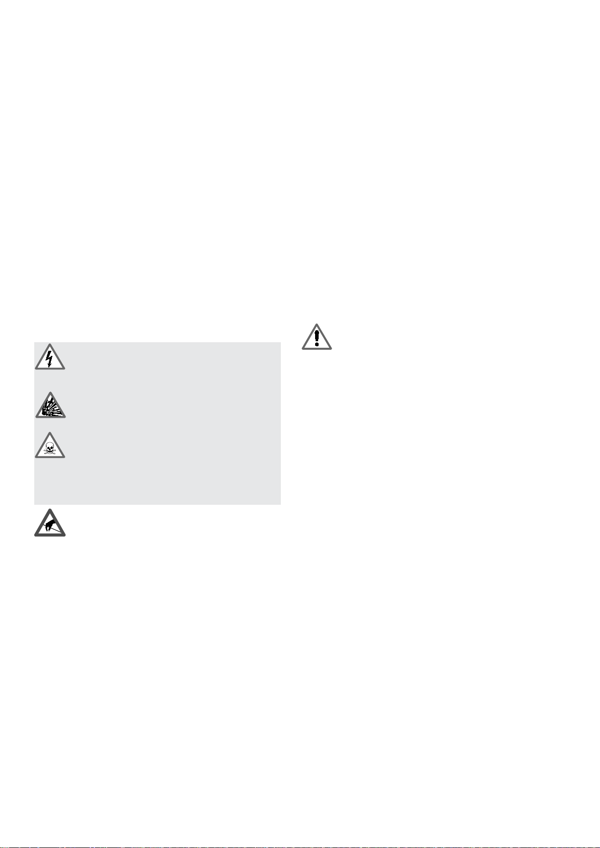
The BEA carries dangerous contact voltage. Unsatisfactory or insufficient maintenance and repair work may
lead to a risk of accident through electric shock.
The regulations governing the calibration of exhaust-gas analyzers in the specific country of use must be complied with.
At half-yearly intervals
the BEA must be serviced by expert, instructed persons.
If an official test seal is broken during such work, proper and
expert repair must be performed and confirmed by the authorized
Service Agent and a new calibration undertaken by the responsible calibration authorities.
Service work
must be recorded in writing, including the following information:
z Time of service
z Type of service work undertaken
z Name of person or company performing the work
These records must be preserved for the duration of five years.
The Operating Instructions must be kept with the BEA so that they
are available at all times.
The owner of the BEA is responsible for compliance
with calibration laws and for regular service and
maintenance.
The BEA must not be used to measure explosive gases.
The exhaust-gas analyzer must not be operated in
rooms where there is a risk of explosion.
During work with toxic gases, care must be taken to
ensure that a concentration which is hazardous to
health cannot arise in the workplace.
Improperly conducted maintenance and repair work
may lead to a risk of intoxication when working with toxic
gases.
The printed circuit boards contain electrostatic sensitive devices.
Observe ESD regulations!
4
2. Testing equipment and settings for the Service software
2.1 Testing equipment
2.2 Calibrating gases (with manufacturer's certificate)
In order to save on calibrating-gas bottles, we recommend a
calibrating-gas bottle filled with mixed gases:
z 1 laptop or PC
z P100
z P140
z Service software for BEA
z ESA module system software to test Engine test functions
z KTS module system software to test OBD functions
i The system software versions for Emissions System Analysis
and the KTS module must be installed on your laptop or PC,
otherwise the Service software will not be fully functional!
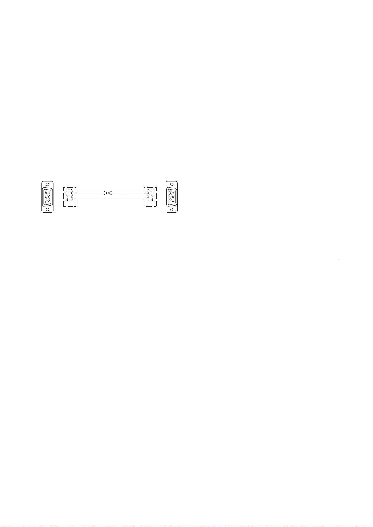
z BEA - PC or laptop, COM1 connecting lead.
As an alternative to the lead shown, the connecting lead for
the data terminal (DTL) 1 684 465 320, can be used.
1
6
9
5
455901-7
1
6
9
5
z Adaptor cable AL350 to check OBD connecting line to
control device.
z Test connector KS350 to check OBD interface in BEA
z 1 flow meter (rotameter), measuring range 1.5 to 2 l/min or
10 l/min, test medium air, 20 °C, 1 bar absolute
z 1 absolute-pressure gauge (barometer) or adjusting barometer
set to absolute pressure. Measuring accuracy 5 hPa (5 mbar)
z 1 gas wash bottle (pearl bottle)
z 1 digital multimeter (DMM)
z 1 DC calibrator, 0 to 15 mV
z 1 stabilizer DC U = 0Volts - 30Volts
z Viton hose for calibrating-gas connection (do not use hoses
of different material)
z 1 U-tube, water gauge 100 cm, inside diameter max. 8 mm
z Compressed air for cleaning exhaust-sample probe and hose
z Torque screwdriver 0.2 - 4 Nm
Insert for inner TORX screws size T15
No. 4 5 % CO + 7.5 % CO
+ 2.000 ppm C3H8 (propane)*,
2
accuracy of analysis ± 1%
In some countries (e.g. Germany), calibrating gases to OIML
Directive R99 A and B are used for calibration. In this case, gas
no. 4 can be dispensed with.
A 2000 ppm vol. C3H8 (propane)*, accuracy of analysis ± 1%
3.5 % vol. CO, accuracy of analysis ± 1%
14 % vol. CO2, accuracy of analysis ± 1%
B 200 ppm vol. C3H8 (propane)*, accuracy of analysis ± 2%
0.5 % vol. CO, accuracy of analysis ± 1%
6 % vol. CO
, accuracy of analysis ± 1%
2
* For practical reasons, the exhaust-gas analyzer module is
calibrated regularly with propane instead of hexane.
When the exhaust-gas analyzer module is calibrated in the
menu Readjustment with test gas in the Test functions
menu, the module is informed of the concentration of the
calibrating gas in ppm propane. The exhaust-gas analyzer
automatically takes account of the required "propane factor".
Additional test equipment and calibrating gas for optional NO
measuring sensor
z NO calibrating-gas bottle: From 1000 to 5000 ppm NO
+ 2 %
z Shutoff valve
z Stopwatch
z 0 - 12 V DC stabilizer
5
2.3 Settings for the Service software
i The Service software contains the functions for AMM
(opacimeter) and the BEA (Bosch Emissions Analysis) control module.
RTM
Your laptop or PC must also have the system software for the emission system
analysis and KTS module installed.
(exhaust-gas analyzer module),
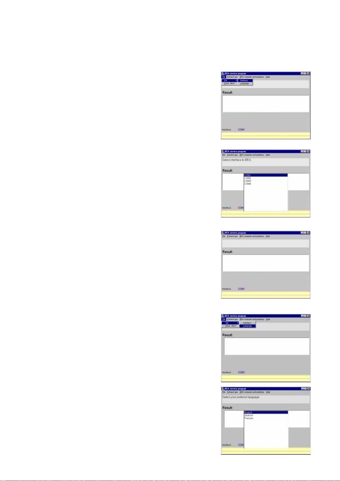
2.3.1 Setting the interface for the Service program
Start the Service program BEAKD.
Open the File menu.
Select Set
Select the appropriate interface and confirm by double-clicking the left-hand
mouse button or by pressing E Enter .
The interface you have selected is displayed below the results window.
and then Interface.
2.3.2 Service Software Language Selection
6
Start the service program BEAKD.
Open the File menu.
Go to Settings and select the Language
menu.
Use the mouse or the o and u keys to
select the laguage for the service program.
Confirm by double clicking the mouse
button or pressing the Enter E key.
The following languages are available:
English
German
French
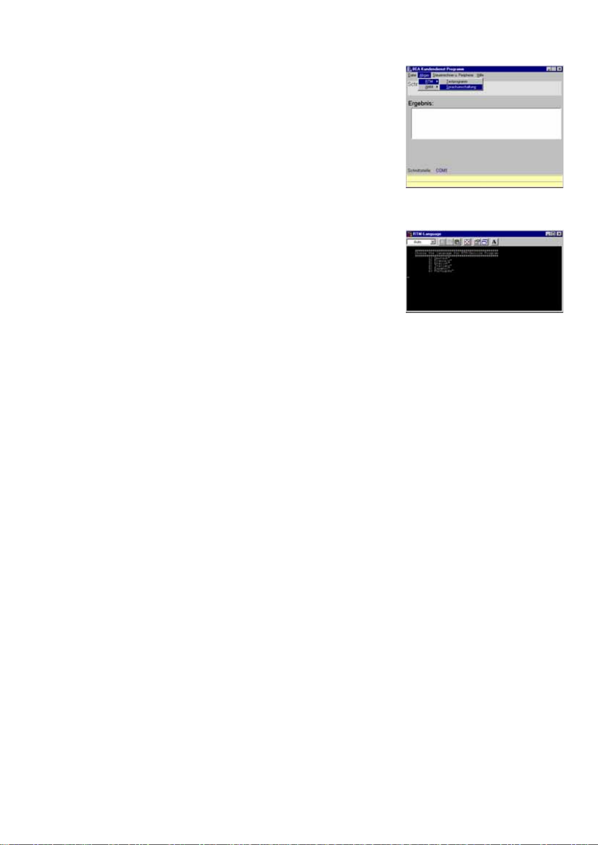
2.3.3 Language Selection for RTM 430 Smoke Opacity Module Service Software
Open the Exhaust Gas menu and select
the RTM menu.
Open the Swap Languages menu.
A DOS window is opened with a language-selection capability.
Choose the language, by pressing
the appropriate number in front of the
language on your keyboard.
After entering the corresponding number,
the language is automatically changed to.
7

3. Brief description of unit functions and Servicing the unit
3.1 Exhaust-gas analyzer module
The exhaust-gas analyzer module is designed for the following
measuring ranges:
z Carbon monoxide (CO) 0...10.00 % vol.
z Hydrocarbons (HC) 0...9999 ppm
z Carbon dioxide (CO
z Oxygen (O
) 0...22 % vol.
2
z Excess-air factor (lambda) 0.500...9.999
z Nitrogen monoxide (NO) 0...5000 ppm vol. NO
3.1.1 Analyzer part (HC, CO and CO
) 0...18 % vol.
2
measurement)
2
3.1.3 Self-test
The BEA performs a self-test during which it checks all its most
important functions. Any malfunctions detected result in an error
message (Section 8).
3.1.4 Adjustment (HC, CO and CO
measuring channels)
2
During 1-point adjustment (recalibration) with calibrating gas, the
measurement effect (difference from zero) is measured. The
analyzer module is informed by means of a nominal value as to
which concentration of calibrating gas corresponds to this
measurement effect.
You may preselect different adjustment options which vary in type
and frequency, to suit your application.
The measuring channels for HC, CO and CO
infrared pulsating-light method.
function using the
2
This technique makes use of the ability of different gases to
absorb infrared rays of a certain wavelength.
An infrared ray is produced by a lamp and interrupted in cycles by
a chopper wheel, then it passes through analysis systems for CO,
HC and CO
sensitive to infrared light of different wavelengths and can there-
in succession. The individual analysis systems are
2
fore be mechanically arranged one behind the other.
Each of these systems consists of an analysis chamber through
which test gas flows, and a receiving chamber filled with a suitable
gas mixture.
The systems are constructed in such a way that when zero gas
(air) flows through the analysis chamber, a maximum electric
alternating-voltage signal – the measured-value signal – is generated in the receiving chambers.
The signal is amplified by the appropriate channel amplifier,
rectified and conveyed on the motherboard to an analog-to-digital
converter (ADC). The digitalized signal is read and stored by the
MPU.
When test gas containing the component to be measured flows
through the analysis chambers, component-specific wavelengths
of the infrared ray are attenuated accordingly. A smaller measured-value signal is generated in the receiving chambers (see gas
circuit diagram, Section 12.5).
3.1.2 System calibration
System calibration is always started automatically when the
system switches to a measuring mode and the infrared measured
values at this moment differ from zero.
During system calibration, a solenoid valve switches the zero-gas
inlet (with carbon canister) into the test-gas duct for the duration
of calibration. During this process, zero gas (air) is used to
determine the actual system sensitivity of the HC, CO and CO
measuring channels. This value is then stored as the zero point.
If the exhaust-gas analyzer module is still in analysis mode after
15 minutes, system calibration is repeated. Here, the analyzer
module automatically checks whether analysis is currently taking
place and, if it is, delays system calibration until all measured
values have fallen to zero.
3.1.5 O
measuring channel
2
The sensitivity of this measuring channel is adjusted automatically
during each system calibration. During this process, the measured oxygen content is set against the compensating air = 20.9 %
and the condition of the O
zero point of the O
cally.
2
measuring sensor is monitored. The
2
measuring channel is recognised automati-
The oxygen measurement function can be deactivated
(Section 4.5, Write parameters
menu).
3.1.6 Compensation of pressure influence
Different levels of atmospheric pressure mean that different
concentrations are measured in the analysis system. In order for
the exhaust-gas analyzer module to achieve a correct measurement, the atmospheric pressure to be taken into consideration is
determined by means of an integral pressure sensor. The exhaustgas analyzer module can then calculate the correct displayed
value itself.
3.1.7 Compensation of temperature influence
Temperature sensors are situated on the receiving chambers and
on the infrared lamp. The operating temperatures measured there
are automatically taken into account during the adjustment of the
exhaust-gas analyzer module and the conversion of the measured
value to the displayed value.
3.1.8 Measurement of excess-air factor (lambda)
The exhaust-gas analyzer module calculates the excess-air factor
(lambda λ) from the measured concentrations of CO, HC, CO
2
and O2. The lambda value is indicated on the display if the
measured CO
content exceeds 2 % and both the oxygen
2
measurement and excess-air measurement functions are activated. The oxygen measurement is extremely important for calculating the excess-air factor. An imprecise oxygen measurement
leads to the incorrect calculation of the excess-air factor. The
lambda measurement function can be deactivated (Section 4.5,
Write parameters menu).
2
8
3.1.9 Corrected CO concentration (CO
vrai
)
3.2 Servicing the unit
The exhaust-gas analyzer module calculates the true CO concentration (CO
process also takes , for example, factors such as leaks in the
) from the concentrations of CO and CO2. This
vrai
exhaust system into consideration.
This function can be deactivated (Section 4.5, Write parameters
menu).
3.1.10 Parameterization
The exhaust-gas analyzer module can be parameterized for its
specific intended tasks in the Set parameters menu (Section 4.5).
Additional possibilities for parameterization are contained in the
Adjustment functions
menu (Section 9). However, these - like
the adjustment functions themselves - can only be accessed if a
test seal has been broken.
3.1.11 Filtration
Particles and aerosols are removed from the test gas by a
cascade of filters.
Particles constitute solid bodies such as dust and soot, while
aerosols are tiny droplets of fluid which condense in the gas duct
and analysis chambers. There they form a coating which may give
rise to error messages.
For this reason, it is imperative to ensure the correct manner of
filtration.
The service work listed below must be performed irrespective of
legal requirements in the country of operation.
3.2.1 Half-yearly service
i At this interval, only work for testing and maintaining opera-
tional readiness must be performed.
1. Replace GF1 filter (Item 1)
2. Replace inlet filter GF2 (Item 2)
3. Check that both PVC hoses are connected to the gas outlet
(Items 3, 4)
4. Visual inspection of exhaust-sample probe (Item 6)
In the case of major contamination, blow out with compressed air against the direction of suction
5. Perform leak test (Sec. 4.2)
6. Update service date (Sec. 4.7.8)
3.1.12 Principle of filtration
The first filter, GF1, filters the majority of particles and aerosols out
of the gas flow. This filter clogs most rapidly and must therefore
be replaced most frequently: about once a week.
The inlet filter, GF2, at second place in the cascade, filters out a
further part of particles and aerosols. The more clogged the filter
is, the smaller the mesh size and thus the better the filtering action.
The filter becomes wet very quickly from water in the exhaust gas.
This moisture washes the aerosols out of the flow of gas and filters
the particles better. A wet filter is therefore desirable!
This filter should be replaced from around once a month to once
a year.
Filters GF3 and GF4 have the task of protecting the internal
pumps. When the filtration system as a whole is being used
correctly, these filters must only be replaced once a year, at the
most.
Filter GF4, in particular, also has a better filtering action when wet
than dry.
459715/8Ha
4
2
3.2.2 Yearly service
3
6
This service work must be performed by expert maintenance
personnel. It consists of the work included in the half-yearly
service plus the additional items:
1
! It is essential to read Sections 3.1.11 (Filtration) and 3.1.12
before replacing the filters!
1. Replace pump protection filters GF 3 and GF4.
i The pump protection filter GF4 is situated in the interior of the
unit.
! When the GF4 filter is replaced annually, the internal piping
should also always be replaced. Use the parts set 1 687 010
125 for this purpose. Be very careful to consult the gas flow
plan in chapter 12.5.
GF4
459715/9Ha
AF1
GF3
9

Procedure:
Using a non-soluble felt pen, write the current date on the
adhesive label 1 689 980 296 and confirm with your signature
(see illustration).
aktuelles Datum
Datum/Date
Unterschrift/Sign
Unterschrift
459558/23 Ha
Stick the completed adhesive labels onto the new GF3 and
GF4 coarse filters.
Install the new GF3 and GF4 coarse filters.
2. Replace the carbon canister AF1 in the zero gas pipe.
3. Check the measuring accuracy of the exhaust-gas analyzer
with calibrating gas.
i Always ensure a flow rate of > 1 l/min when letting gas flow
through the calibrating-gas inlet. Allow a sufficient warm-up
time (min: 5 minutes).
Click on Test functions (Sec. 4.7) and open the menu item
Analysis mode (Sec. 4.7.6).
Automatic zero calibration takes place.
Let test gas no. 4 (sensitivity test) or single gases of the
appropriate concentration in succession flow through the
exhaust-gas analyzer via the calibrating-gas inlet. Note down
the displayed values.
Next, use test gases no. 5 and no. 1 (gas mixture for sag test)
to check linearity, and note down the displayed values.
If the display deviates from the certified calibrating-gas value
during a measurement (sensitivity or linearity) by more than 5
%, replace the measuring bank (Section 10.10).
! If regular calibration is required due to special regulations,
execute the menu Readjustment with test gas (4.7.5) in the
Test functions menu (4.7). This will reset the monitoring
clock.
10
4. Checking the AMM
exhaust-gas analyzer
module
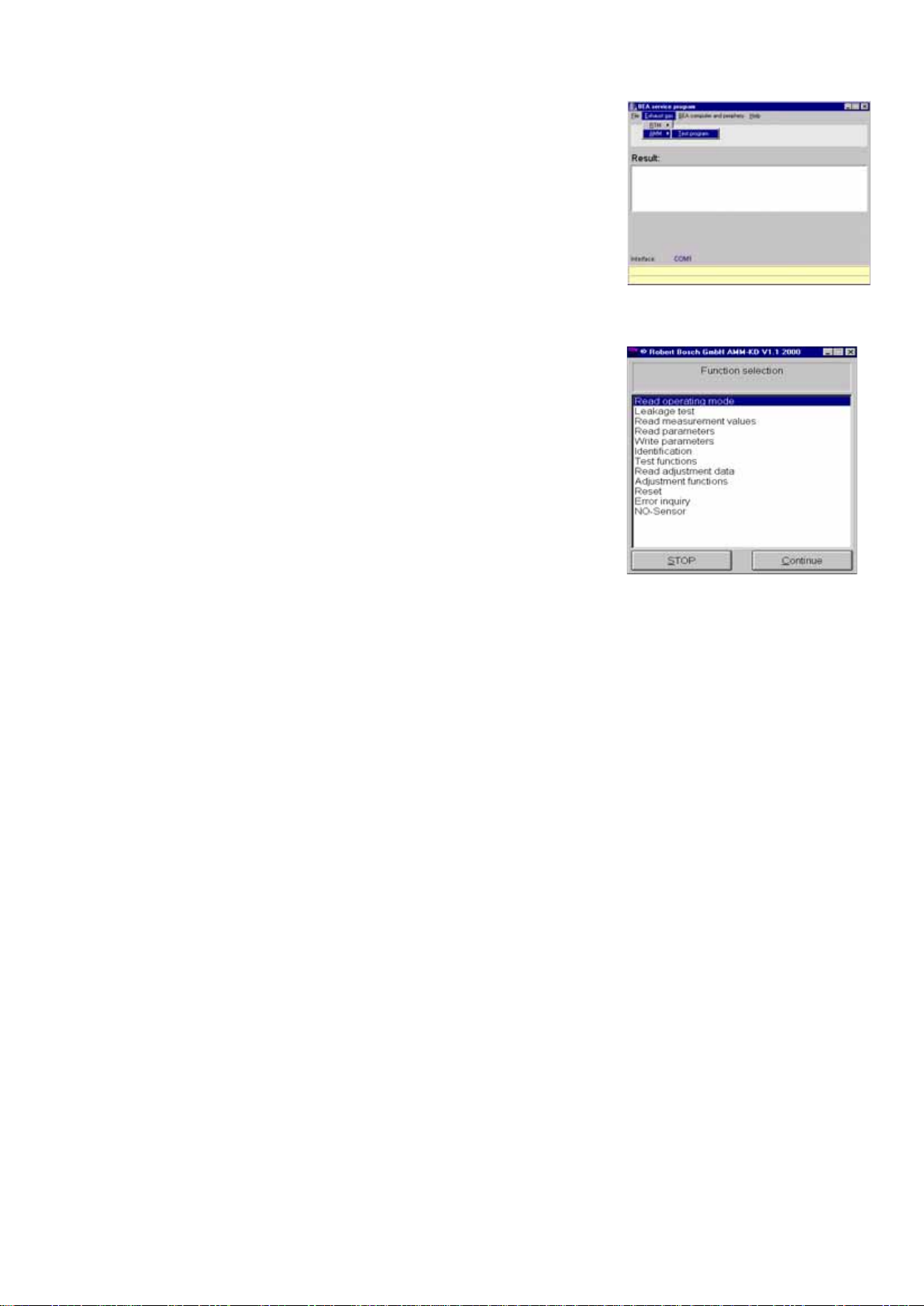
Open the Exhaust gas menu and select
AMM.
Then choose the Test program
Function selection menu (main
The
menu.
menu) opens.
The Function selection menu contains the
following items:
Read operating mode Display the current status (mode) of the exhaust-gas
analyzer module.
Leakage test Perform a manual leak test.
Read measurment values Display current measured values of HC, CO, CO
, lambda CO
O
2
and air pressure.
cor
Read parameters Read out set parameters.
Write parameters Enter parameters which are important for the opera-
tion of the exhaust-gas analyzer module (countryspecific stipulations).
Identification Read out software version and checksum.
Test functions Check unit functions.
Read adjustment data Display setting data important for operation of the
exhaust-gas analyzer module (country-specific stipulations).
Adjustment functions Settings for the exhaust-gas analyzer module.
Reset Restart the exhaust-gas analyzer module. (When this
option is selected, the exhaust-gas analyzer module
is disabled for approx. 15 s).
,
2
Error inquiry Read out the internal fault memory.
NO - Sensor Menu for operating the NO - Sensor.
11
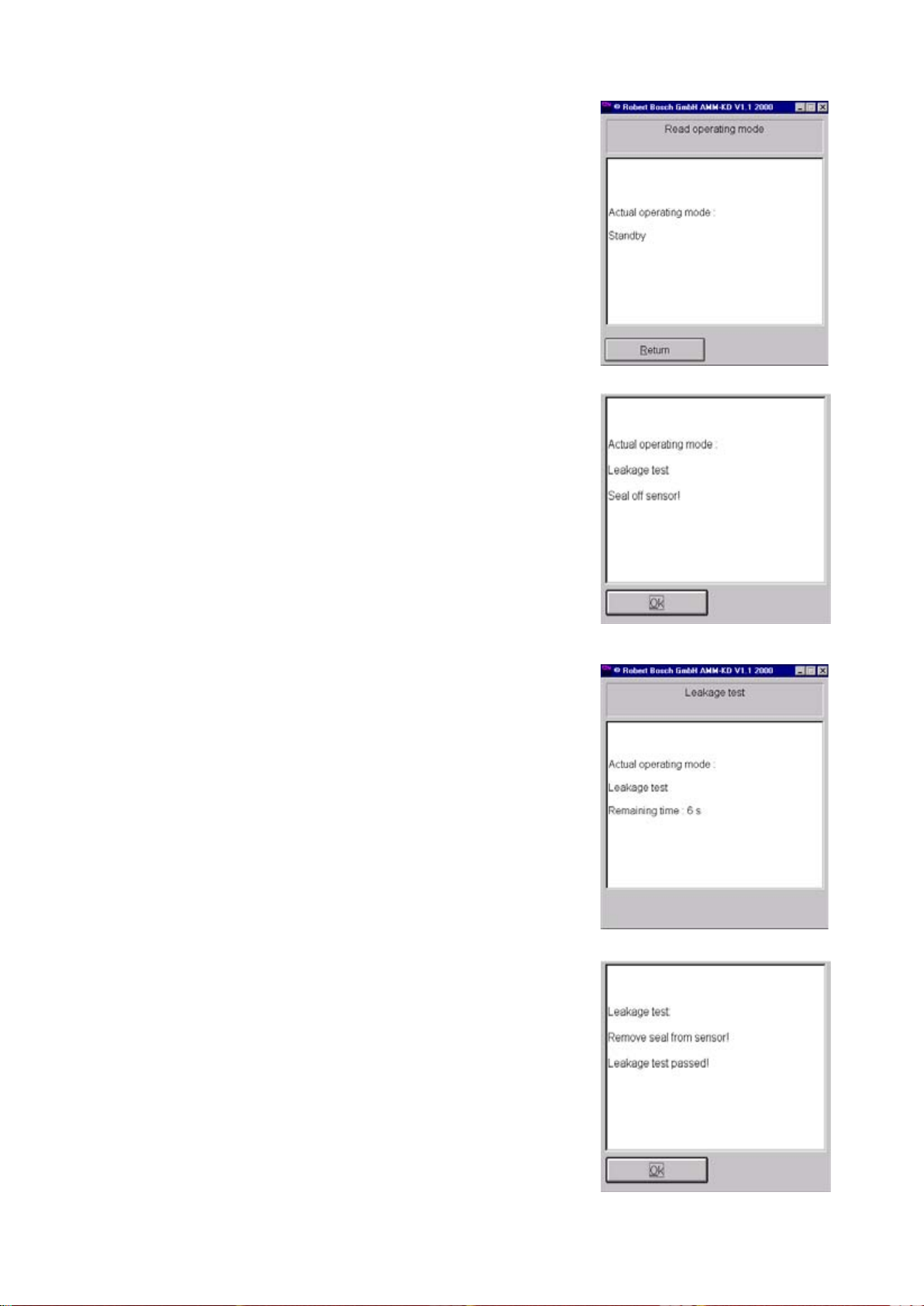
4.1 Read operating mode
The current status (mode) of the exhaustgas analyzer module is displayed.
Depending on when this menu is started,
the following modes may be displayed:
z Leakage test
z Warm-up phase
z Standby
z Error message
4.2 Leakage test
This menu allows you to perform a leakage
test manually to check the tightness of the
exhaust-gas analyzer module.
Seal off the exhaust-sample probe with
the plastic hose or the test bush and
confirm by pressing E or clicking OK.
Follow the instructions on screen.
The pump is then switched on and off in
cycles over a period of approx. 3 sec. until
a certain level of vacuum is reached. After
this, the exhaust-gas analyzer module
measures the drop in pressure over a
period of 15 s. The time is counted backwards from 15 s to 0.
12
Remove the seal from the exhaust-sample
probe and confirm by pressing E or
clicking OK.
If the leakage test is failed, perform trouble-shooting as described in Section 8.
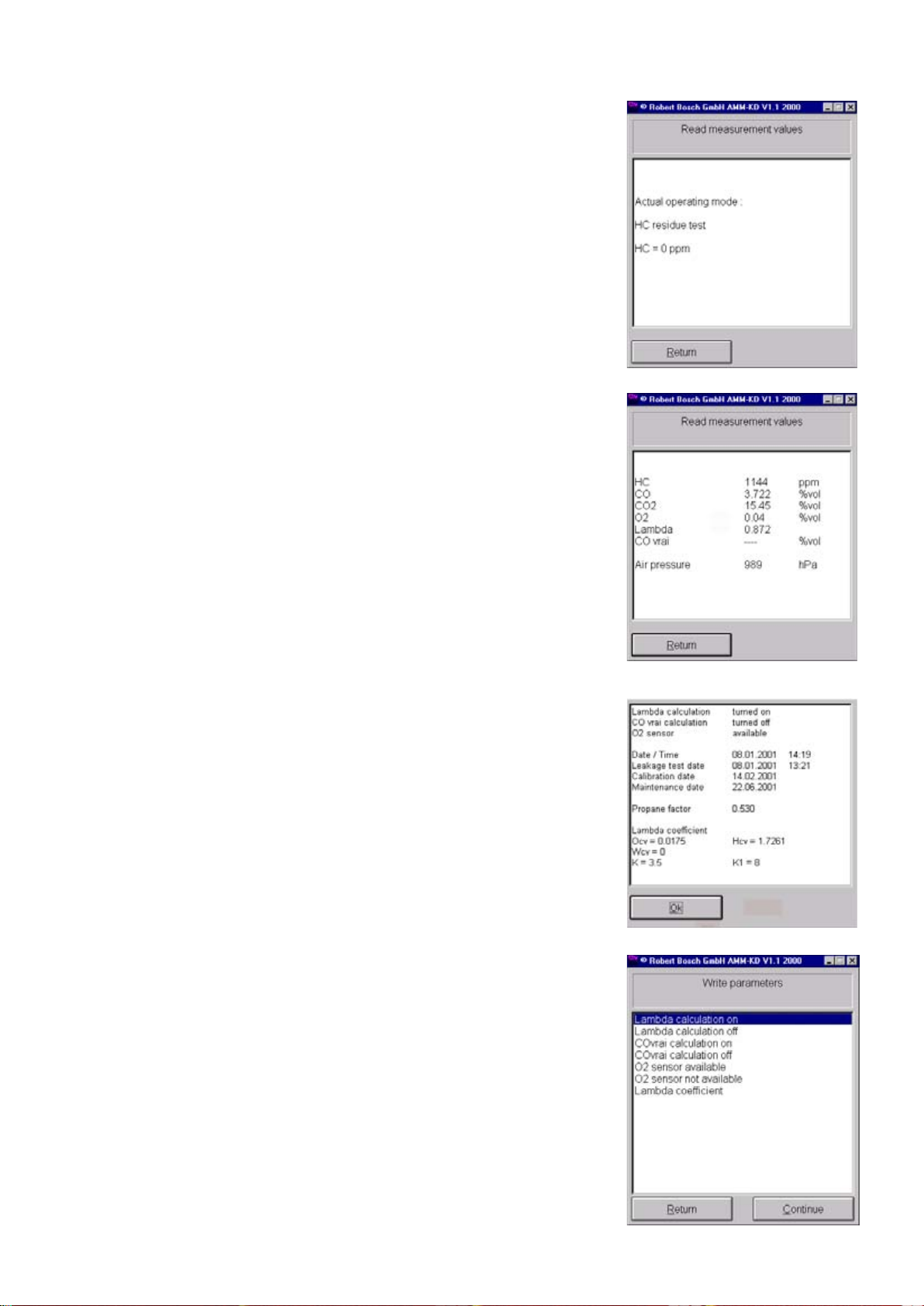
4.3 Read measurement values
After zero calibration, an HC residue test
takes place.
Next, the current measured values for HC,
CO, CO
pressure are displayed.
, O2, lambda, CO
2
and air
cor
4.4 Read parameters
4.5 Write parameters
The parameters set in the Set parameters
mode (Section 4.5) are displayed. For
example:
Parameters specific to the country of use
or required by law are set in this menu.
13
4.5.1 Country-specific settings
Parameter settings
Parameter Germany Standard EU Denmark Switz. France Holland Italy
Lambda calculation ON ON ON O N ON ON ON
CO
calculation OFF OFF ON OFF ON OFF OFF
cor
measurement ON ON ON ON ON ON ON
O
2
Adjustment data settings
Setting Germany Standard EU Denmark Switz. France Holland Italy
Recalibration interval 365 days 365 days 365 days 365 days 365 days 365 days 365 days
Gases for recalibration HC, CO, HC, CO, HC, CO, HC, CO, HC, CO, No setting HC, CO,
CO
2
CO
2
CO
2
CO
2
CO
2
CO
2
Reaction when recalibration Disable No setting No setting Disable No setting Message No setting
due
Leak test configuration Days Days NO Days NO Days Days
Leak test interval 1 day 1 day NO 1 day NO 1 day 1 day
HC residue test YES YES YES YES YES YES YES
National regul. complied with YES NO YES YES NO YES YES
Change CO
setting Disabled Enabled Disabled Disabled Enabled Disabled Enabled
cor
Service interval 183 days 183 days 183 days 183 days 183 days 183 days 183 days
14
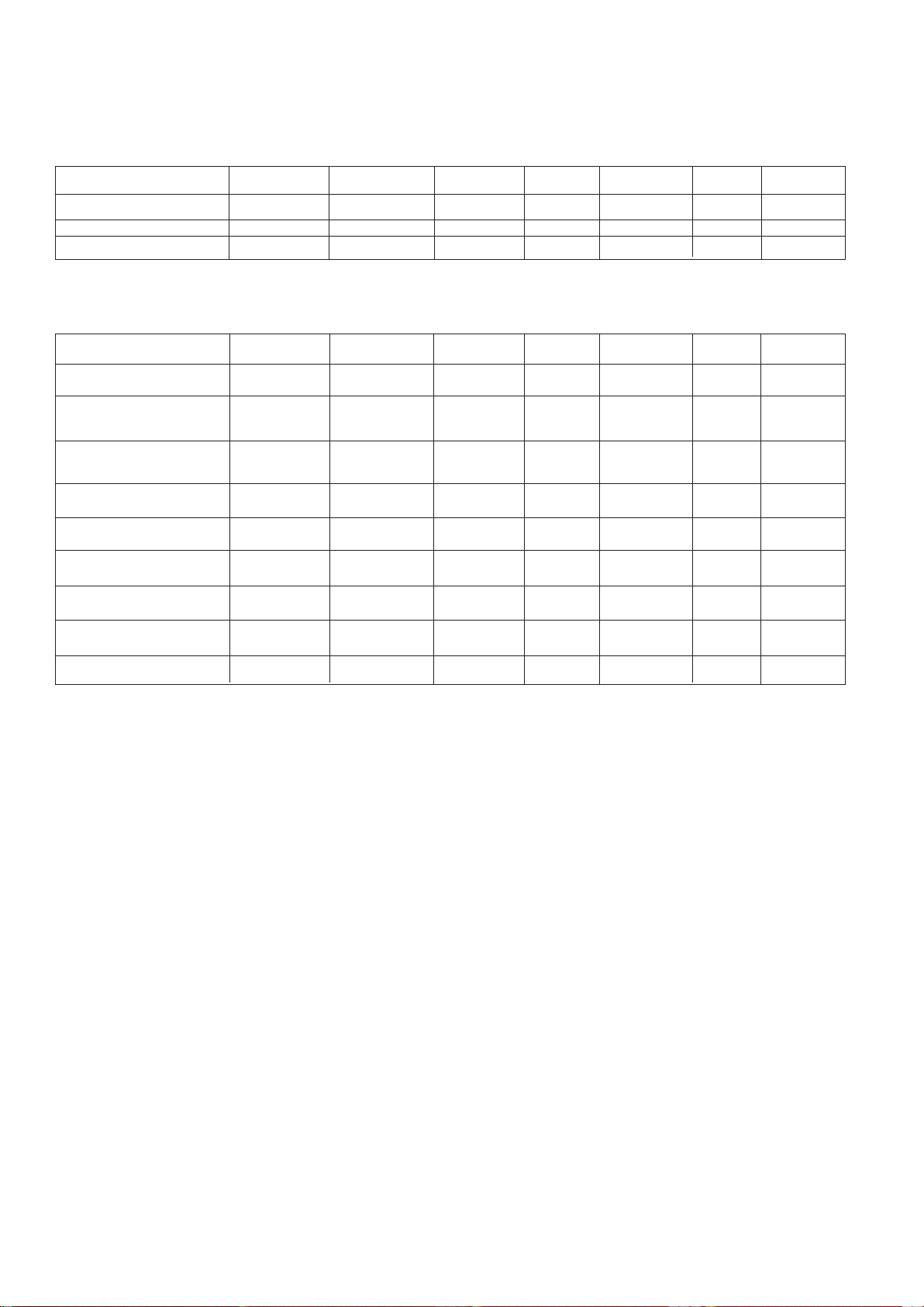
4.5.2 Lambda calculation On
Open the Lambda calculation on menu
using the o u keys and confirm with E or
by double-clicking the mouse.
The OK box is displayed for approx. 1 s.
Lambda calculation is now activated.
4.5.3 Lambda calculation Off
4.5.4 CO
calculation On
vrai
Open the Lambda calculation off
menu using the o u keys and confirm
with E or by double-clicking the mouse.
The OK box is displayed for approx. 1 s.
Lambda calculation is now deactivated.
Open the CO
calculation on menu
vrai
using the o u keys and confirm with E or
by double-clicking the mouse.
The OK box is displayed for approx. 1 s.
calculation is now activated.
CO
cor
4.5.5 CO
calculation Off
vrai
Open the CO
calculation Off menu
vrai
using the o u keys and confirm with E or
by double-clicking the mouse.
The OK box is displayed for approx. 1 s.
calculation is now deactivated.
CO
cor
15
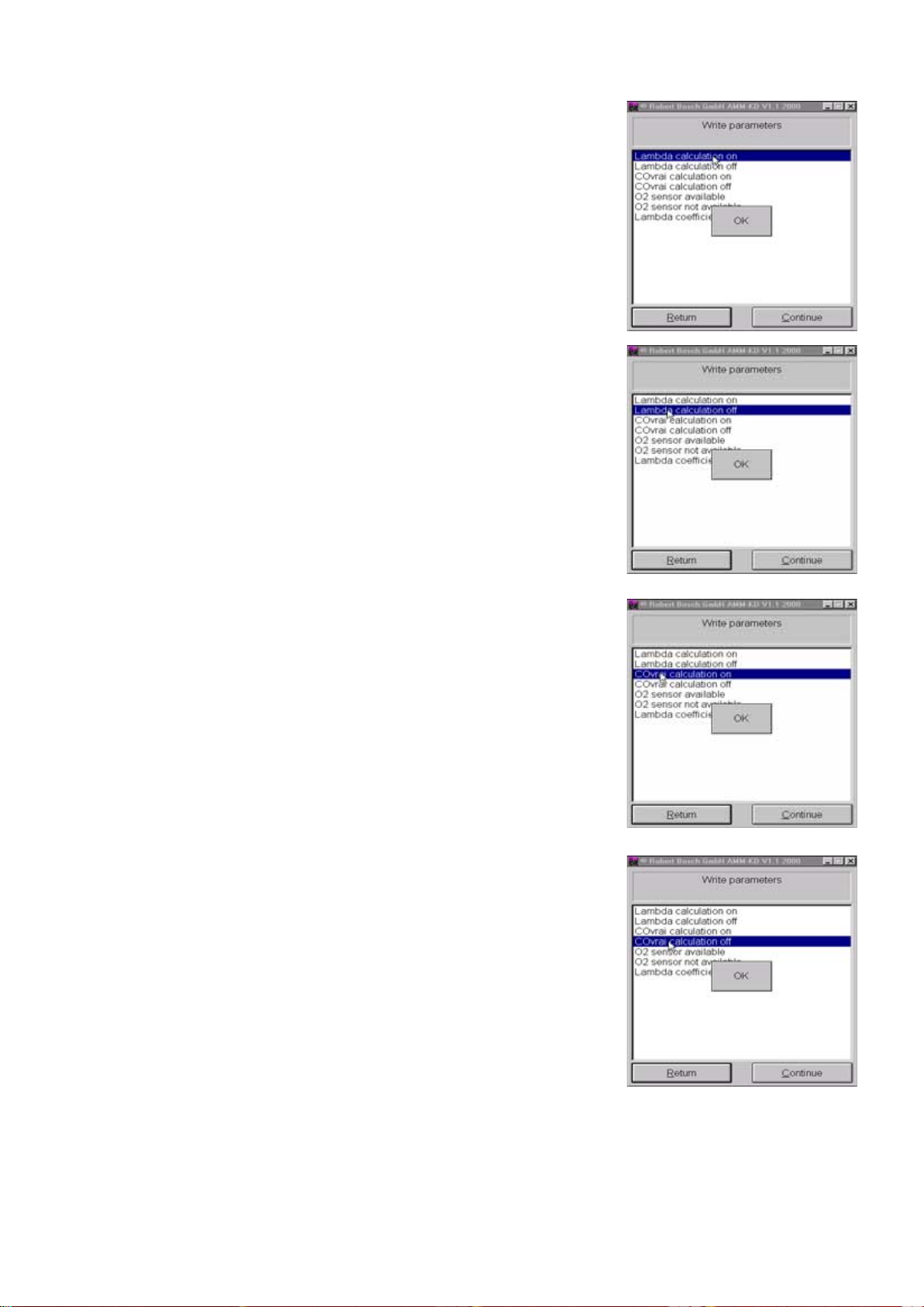
4.5.6 O
sensor available
2
Open the O2 sensor available menu using
the oukeys and confirm with E or by
double-clicking the mouse.
4.5.7 O
sensor not available
2
After confirmation that the O
sensor is not
2
available, the measuring chamber's
measuring computer (SI BENCH) is restarted. After this it jumps back to the Set
parameters sub menu.
i The exhaust-gas analyzer is then once
more in the warm-up phase. Further
measurement with the Service software is disabled for 60 seconds. A
message appears on screen.
Open the O
sensor not available menu
2
using the ou keys and confirm with E or
by double-clicking the mouse.
After confirmation that the O
available, the measuring chamber's
sensor is not
2
measuring computer (SI BENCH) is restarted. After this it jumps back to the Set
parameters sub menu.
i The exhaust-gas analyzer is then once
more in the warm-up phase. Further
measurement with the Service software is disabled for 60 seconds. A
message appears on screen.
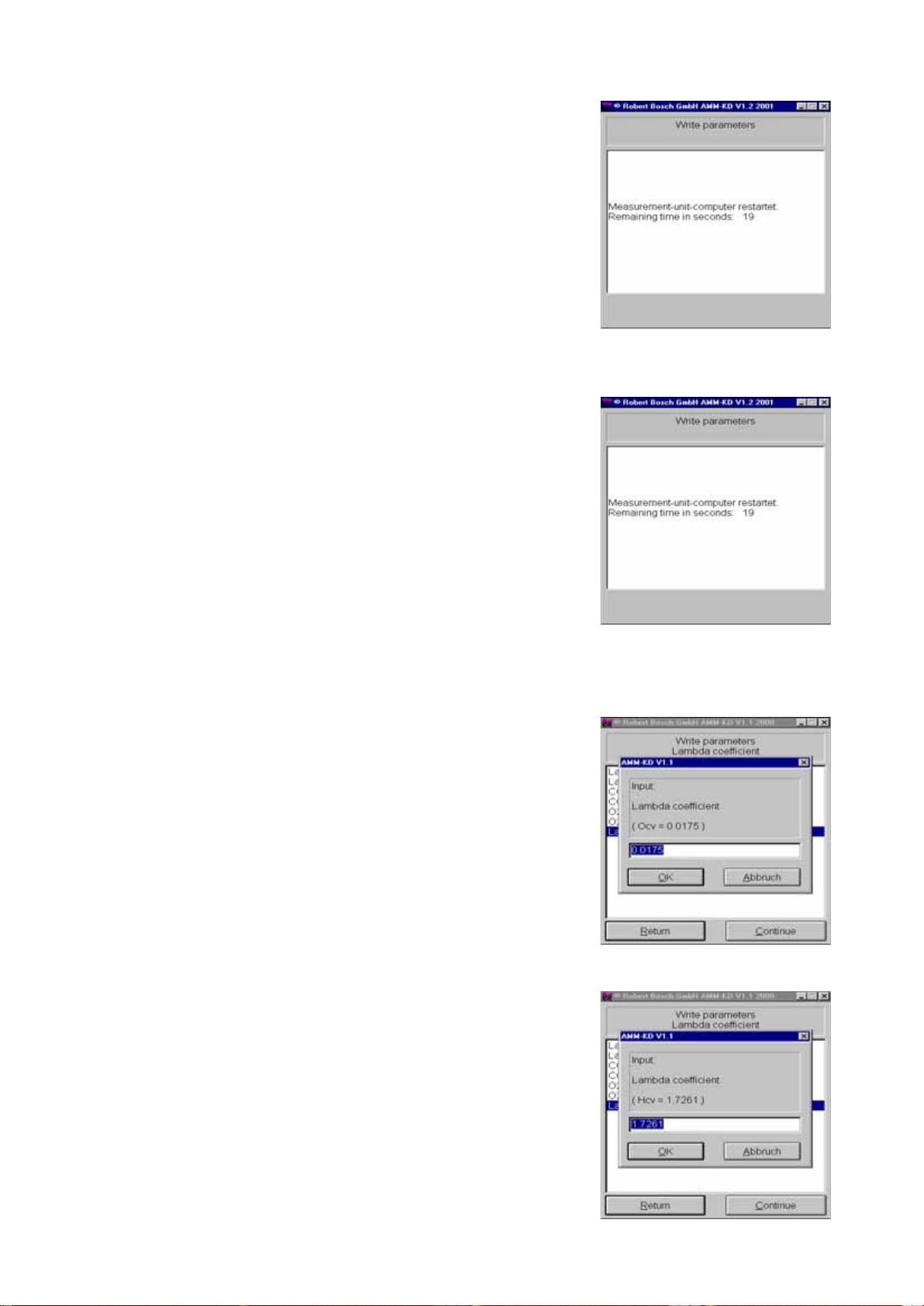
4.5.8 Entering lambda coefficients
OCV and HC
V
i Lambda coefficients must also be set
in accordance with regulations specific to the country of use and must be
stipulated by the law of that country.
Lambda coefficients OC
and HC
V
are fuel-specific values and are required to calculate the lambda value.
Enter the values for OC
on the keyboard
V
and confirm by clicking OK or by pressing E.
e.g.: 0.0175.
Enter the values for HC
on the keyboard
V
and confirm by clicking OK or by pressing E.
e.g.: 1.7261.
V
16
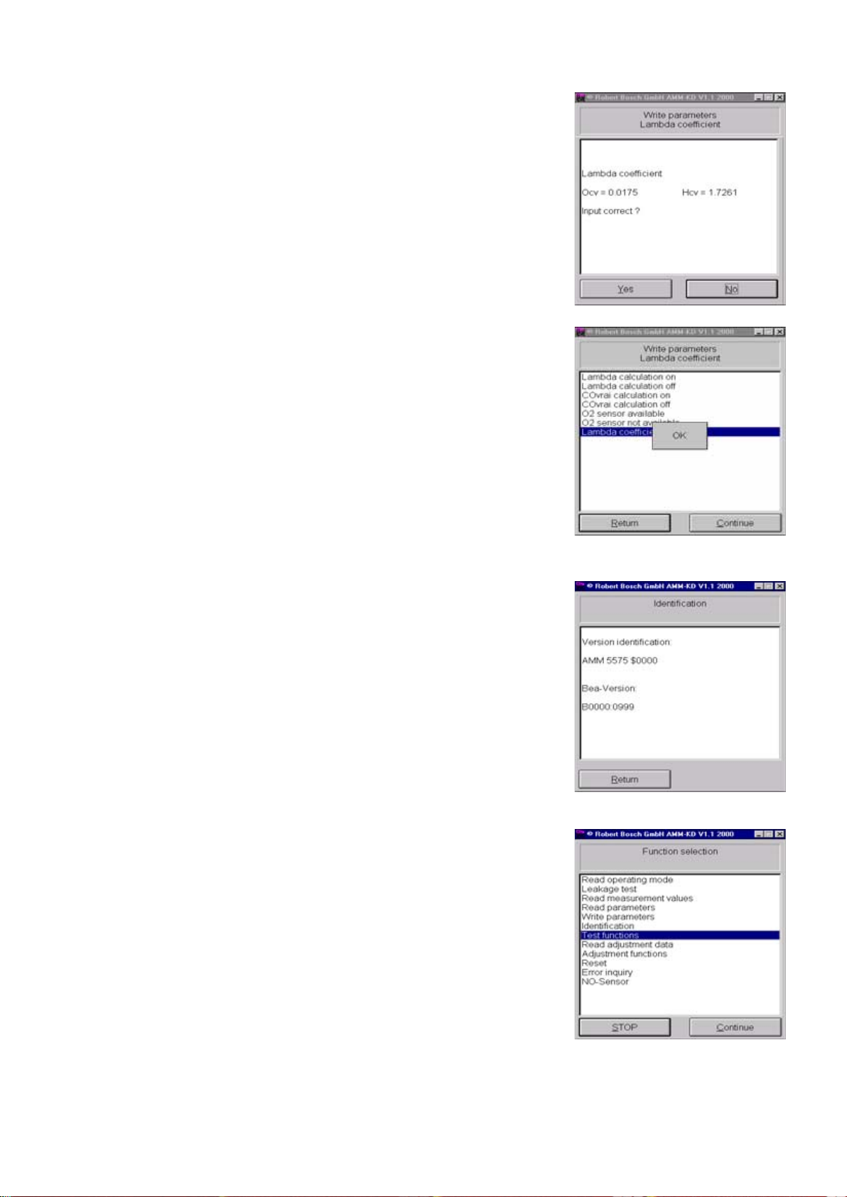
4.5.8 Entering lambda coefficients
HC
and OC
V
V
You are now asked if your entry is correct.
Confirm your entry by clicking Yes or by
selecting Yes with the v z buttons and
pressing E.
The OK box is displayed for approx. 1 s.
The HC
and OCV values are stored in the
V
exhaust-gas analyzer.
If you have entered the values incorrectly,
click No or cancel your entry with E.
Enter the lambda coefficient values again.
4.6 Identification
4.7 Test functions
The software version and checksum of the
exhaust-gas analyzer module are displayed. For example (see screenshot):
You can test various functions of the
exhaust-gas analyzer module in the Test
functions menu.
17
4.7.1 Pump On
Select this menu by double-clicking the
mouse or with the o u keys and confirm
with E.
The pump is switched on and the OK box
is displayed for 1 s.
This function can be used, for example, to
purge the exhaust-gas analyzer module if
it has been contaminated with HC.
4.7.2 Pump Off
4.7.3 Install new O2 sensor
4.7.4 O2 measurement
Select this menu by double-clicking the
mouse or with the o u keys and confirm
with E.
The pump is switched off and the OK box
is displayed for 1 s.
See Section 10.11.
Start the menu by double-clicking the
mouse or with E.
The pump is switched on and zero calibration takes place. During this process, the
measuring channel is recalibrated to
O
2
20.9% O
(this same calibration is also
2
performed automatically during each
system calibration with zero gas/air).
18
After zero calibration, the pump is switched off.
The exhaust-gas analyzer module displays
the concentration of oxygen with the current ADC voltage value below it.
If the current ADC voltage lies at the lower
threshold of 7 mV, you must replace the
measuring sensor (Section 10.11).
O
2
Nominal voltage: 7 mV - 11 mV
4.7.5 Readjustment with test gas i A distinguishing feature of the exhau-
st-gas analyzer module is the excellent long-time stability of its measuring accuracy. Despite this, the exhaust-gas analyzer may be required
by law or by the regulations of approval authorities to be recalibrated with
calibrating gas at given intervals.
To recalibrate the exhaust-gas analyzer,
you will need a calibrating-gas mixture
with the following concentrations (depending on requirements):
HC: 400 to 2000 ppm vol C3H8,
in propane
entry
CO: 1% to 10% vol CO
CO2: 5% to 18% vol CO
2
Using the keyboard, enter the calibratinggas values for CO as stated on the certificate.
Confirm your entry of these values by
clicking OK or by pressing E.
Using the keyboard, enter the calibratinggas values for CO
as stated on the certifi-
2
cate.
Confirm your entry of these values by
clicking OK or by pressing E.
Using the keyboard, enter the calibratinggas values for HC as stated on the certificate.
Confirm your entry of these values by
clicking OK or by pressing E.
19
4.7.5 Readjustment with test gas Set the flow to
i Only push the calibrating-gas hose
onto the calibrating-gas inlet following successful zero calibration.
The calibrating-gas mixture must be fed
into the calibrating-gas inlet.
The exhaust-gas analyzer module performs zero calibration.
> 1 l/min.
After zero calibration, push the calibratinggas hose onto the calibrating-gas inlet.
Start the flow at
The calibrating-gas values are displayed.
Over a period of 30 seconds, the software
of the exhaust-gas analyzer module compares the measured values with the
entered nominal values.
If readjustment with test gas has been
successful, quit the menu by clicking on
OK or with E.
The screen now returns to the Test
functions menu.
i If recalibration was unsuccessful, the
fault is stated in plain text. Repeat the
recalibration process.
> 1 l/min.
20
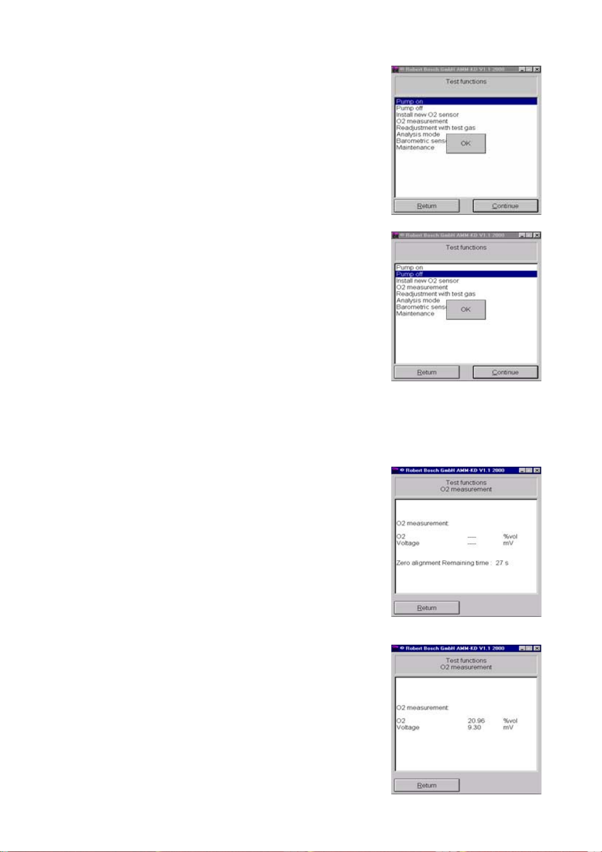
4.7.6 Analysis mode
In this mode, measured values are analyzed
whilst the pump is switched off. This saves
on calibrating gas.
i Drift correction is ineffectual in this
mode, as the warm-up phase has
been bypassed. The zero points therefore drift and may lead to errors.
Once you have started this menu, zero
calibration takes place.
Push the calibrating-gas hose onto the
calibrating-gas inlet and start the flow at
> 1 l/min.
Compare the measured values with the
calibrating-gas values.
In the event of deviations, perform troubleshooting as described in Section 10,
Repairs.
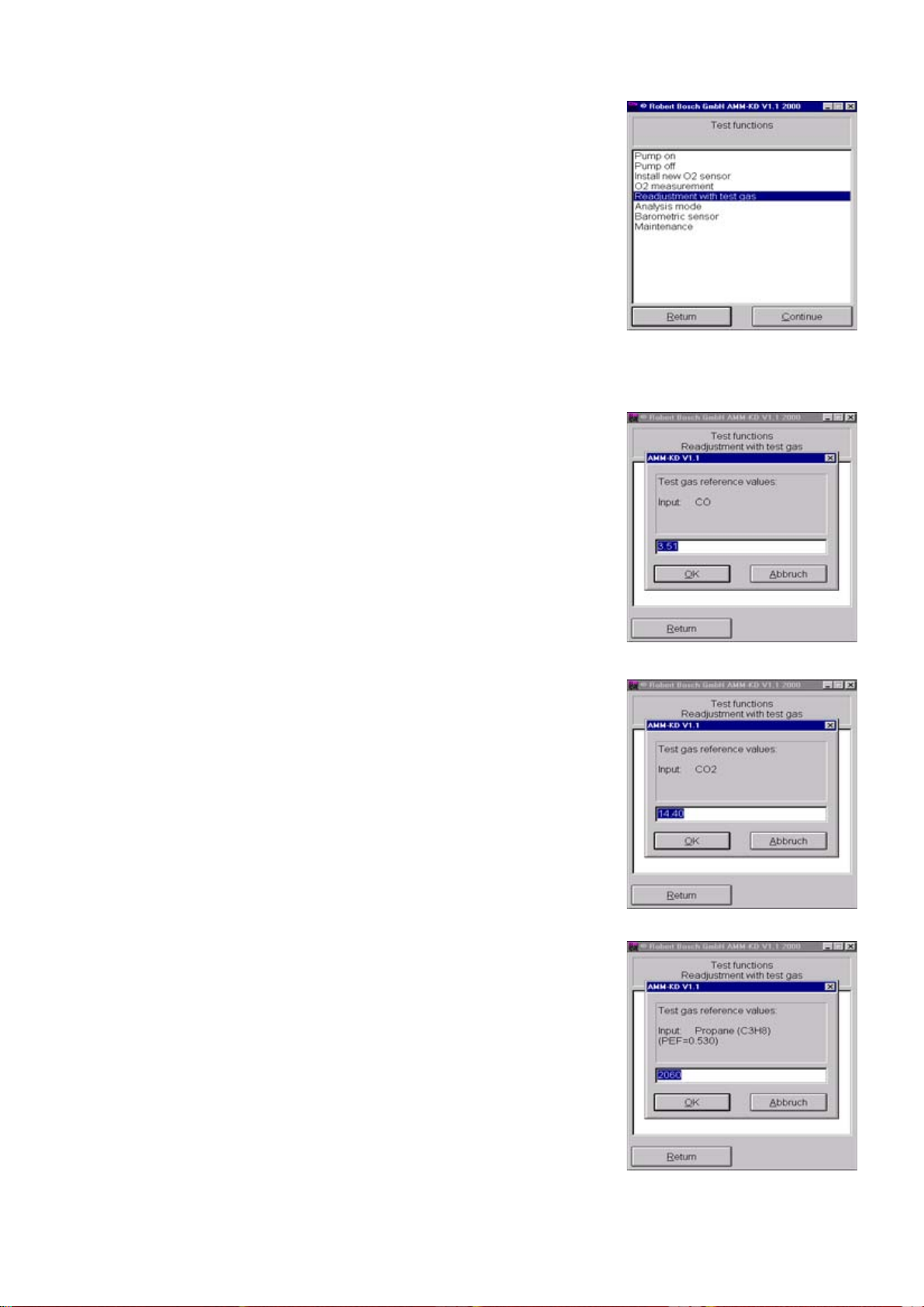
4.7.7 Barometric sensor
The current air pressure is displayed in hPa.
Return to the Test functions menu by
clicking Back
or by pressing E .
21
4.7.8 Maintenance (service date)
i In the case of service intervals stipula-
ted by law, confirm completed service
on the exhaust-gas analyzer. This sets
the internal clock to the next service
date.
Select Yes by clicking on it or using the
tab key .
Confirm that service
by clicking Yes or by pressing E.
Confirm the new service date by clicking
OK or with E. The screen now returns to
the Test functions menu.
has been performed
4.8 Read adjustment data
Here, the parameters set in the Adjustment functions menu are read out.
Quit the Read adjustment data menu
by clicking OK or with E.
22
4.9 Adjustment functions
i Make sure that the Service switch is
set to On
functions menu.
For details on how to adjust the exhaustgas analyzer module and undertake
country-specific settings, please refer to
Section 4.5.1 (country-specific settings).
Return to the function menu by clicking
Back or by pressing keys Alt + B.
before you open the Setting
4.10 Reset
A reset must be performed when entries
have been modified in the Setting
functions menu. These modified
settings will only be stored in the
flashprom of the exhaust-gas analyzer
module after a reset.
Select Yes by clicking it or with the tab
key . Confirm that you wish to perform
a reset with E or by double-clicking the
mouse.
The fault memory is deleted and the
exhaust-gas analyzer module is restarted.
i For approx. 15 s, the exhaust-gas
analyzer module has no connection to
the laptop or PC.
The following message therefore appears:
The measuring device reported hardware
failure!
The error code must be read!
After 15 s, restart the Service program
with E or by clicking OK.
4.11 Error inquiry
Any current faults in the exhaust-gas
analyzer module are displayed in plain
text.
Confirm the readout of the fault memory
with E or by clicking OK. The fault
memory is deleted and the screen returns
to the Function menu.
i If a fault still remains in the exhaust-
gas analyzer, this will be displayed
again.
23
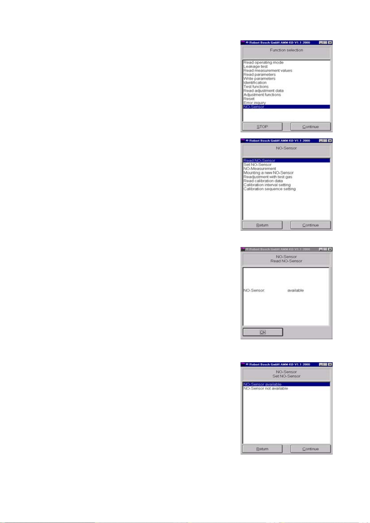
4.12 NO-Sensor
i This menu is only for BEA's equipped
with a retrofit NO measuring sensor!
This menu is used for monitoring, installing and checking the NO measuring sensor.
Start the menu with E or by doubleclicking the mouse.
The following menus can be executed:
z Read NO-Sensor
z Set NO-Sensor
z NO-Measurement
z Mounting an new NO-Sensor
z Readjustment with test gas
z Calibration interval setting
z Calibration sequence setting
4.12.1 Read NO-Sensor
4.12.2 Set NO-Sensor
The status of the NO measuring sensor is
displayed in this menu.
In this menu, the BEA is informed as to
whether or not an NO measuring sensor is
installed.
Confirm your selection of this menu with
E or by double-clicking the mouse.
The OK box appears for 1 s.
24
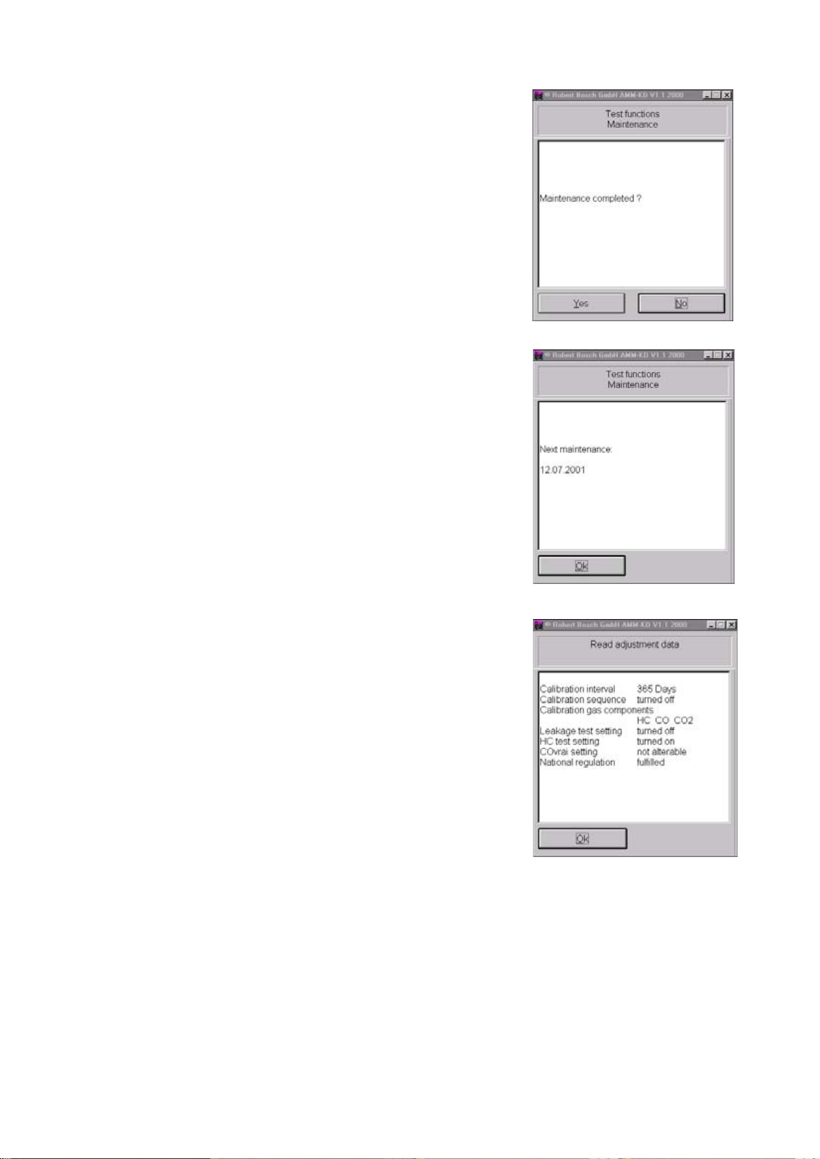
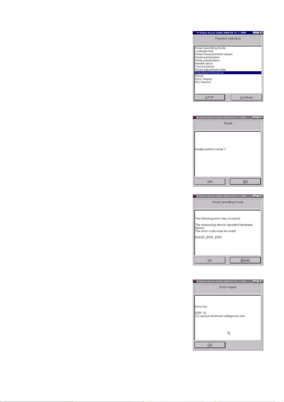
4.12.3 NO-Measurement
This menu is used to check the NO
measuring sensor.
Start the NO test by pressing E or by
double-clicking the mouse.
Zero calibration now takes place.
After zero calibration, the data of the NO
measuring sensor are displayed.
Limit values with air:
NO < 20ppm NO
Voltage 3.290 V
Current 10 µA
+ 0.040 V
+ 10µA
If the limit values are not complied with,
perform trouble-shooting as described in
Section 10.20.
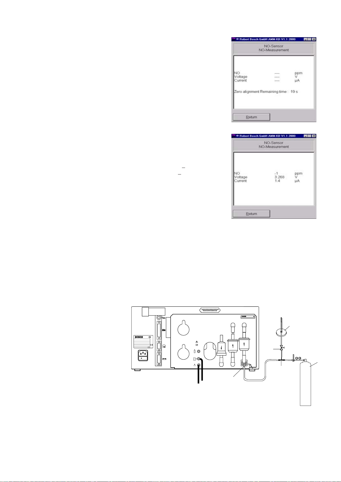
4.12.4 Mounting a new NO-Sensor
Return to the NO menu by clicking Back
or by pressing Alt + B.
i See Section 10.20 for sensor
installation
After the NO measuring sensor has been installed, it must be calibrated. The date of
calibration is written in the flashprom, enabling the age of the NO measuring sensor to be
determined subsequently at any time.
The same calibrating gas is used for calibrating the NO measuring sensor as for
recalibration.
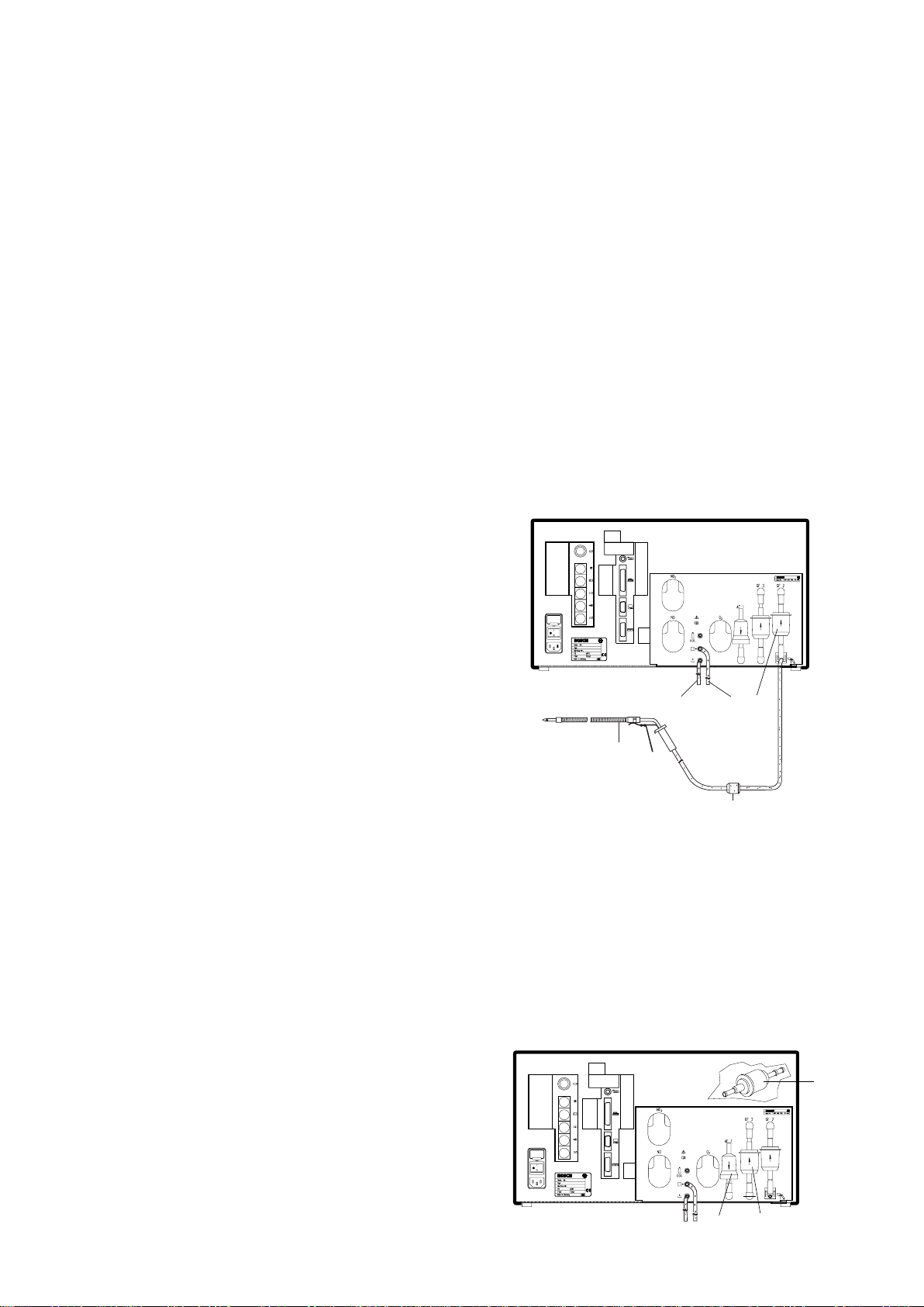
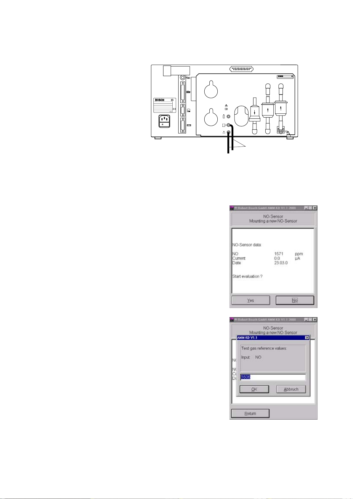
Before commencing calibration, connect the BEA to the calibrating-gas bottle as shown
in the illustration below.
Best. Nr. 1687 022 768 FD xxx
Best.- Nr.
Typ
Geräte - Nr.
FD U ( V )
P ( W ) F ( Hz )
Made in Germany
GF 3 GF 2
AF 1
O
2
088
cal
459737/25Ha
3
5
2
4
NO
1
1 Calibrating-gas bottle
2 Flow meter (rotameter)
3 Shutoff valve
4 Tee
5 Test-gas inlet
25
4.12.4 Mounting a new NO-Sensor
! For initial calibration, it is imperative that the hoses (1) are of the same length and are
connected to the gas outlets of the exhaust-gas analyzer in the same manner as will
actually be the case during subsequent operation by the user.
Best. Nr. 1687 022 768 FD xxx
GF 3 GF 2
AF 1
Best.- Nr.
Typ
Geräte - Nr.
FD U ( V )
P ( W ) F ( Hz )
Made in Germany
088
O
2
cal
459737/26Ha
1
i If the outlet hoses are shortened or lengthened, calibration must be performed again.
The signal from the NO measuring sensor is very sensitive to vibrations from the
pump. The strength of these vibrations depends upon the length of the outlet hoses.
Following successful calibration, the timer for monitoring the set recalibration interval
is started.
- Start evaluation by clicking on Yes or
selecting this button with the z key and
confirming with E.
26
Using the keyboard, enter the calibratinggas value in ppm NO.
i If the calibrating-gas value is stated
on the certificate in mg/m
3
you must
convert this value to ppm.
The formula required for conversion
is:
Test gas value x 0.737.
Example:
2179 mg/m
3
= 1606 ppm NO
Confirm your entry with E or by clicking
OK.
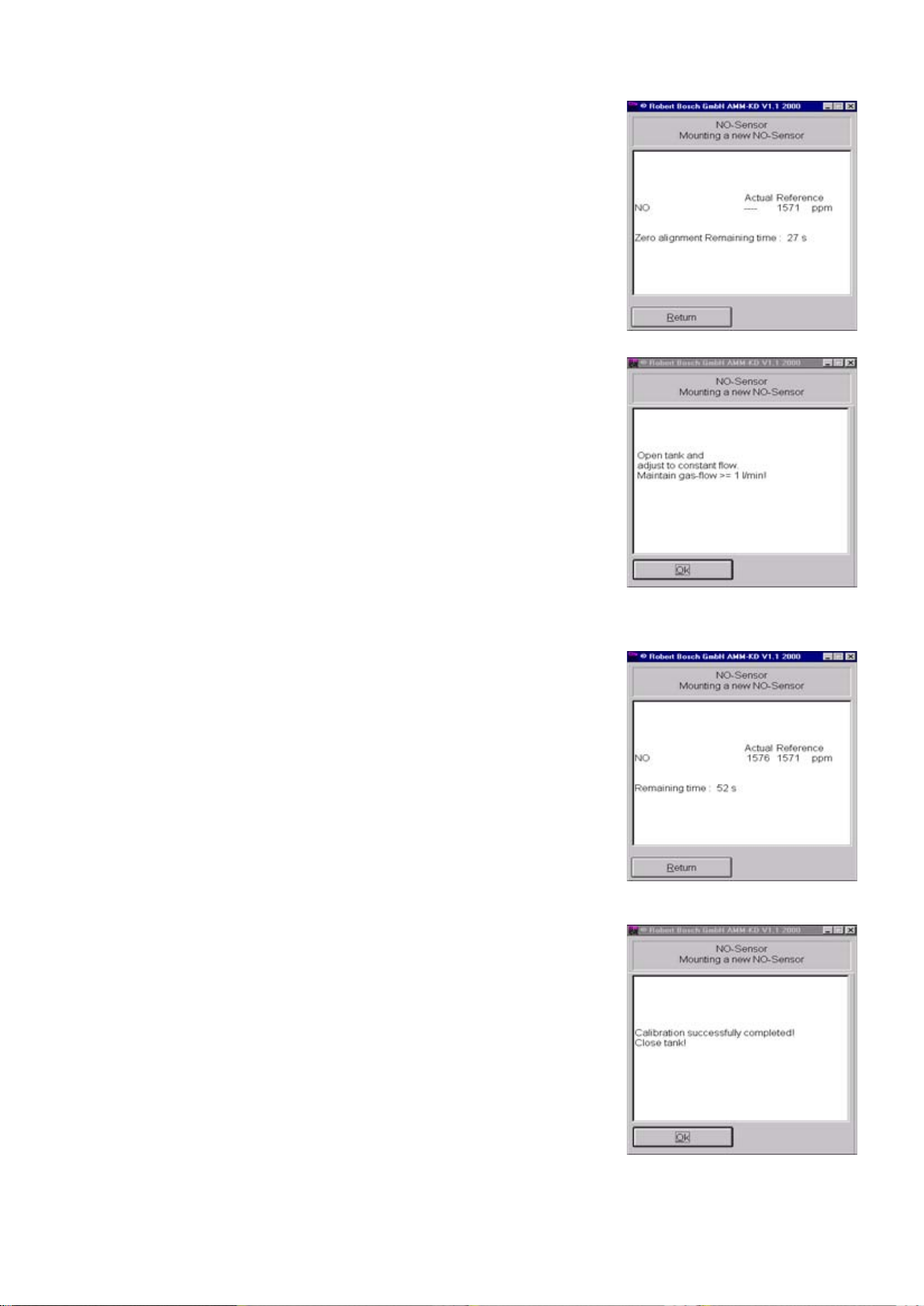
4.12.4 Mounting a new NO-Sensor Zero calibration is performed.
Allow calibrating gas to flow through the
BEA in line with the instructions on
screen.
Open the Test-gas bottle sufficiently to
allow some Test gas to continually flow
out through the rotameter, even with the
pump running (pressure-less calibration).
i The NO measuring sensor is very
sluggish. An "advance flow" through
the NO measuring sensor is therefore
necessary.
After this flow, confirm with E or by
clicking OK.
Assessment is performed. The remaining
flow time is displayed.
After calibrating gas has flown through
the BEA, the measured NO value, the
corresponding test current and the date
calibration are displayed.
To end calibration of the NO measuring
sensor, confirm No by pressing E or
clicking on No.
of
You will now return to the NO-Sensor
menu, and the timer for the adjustment
interval is started.
27
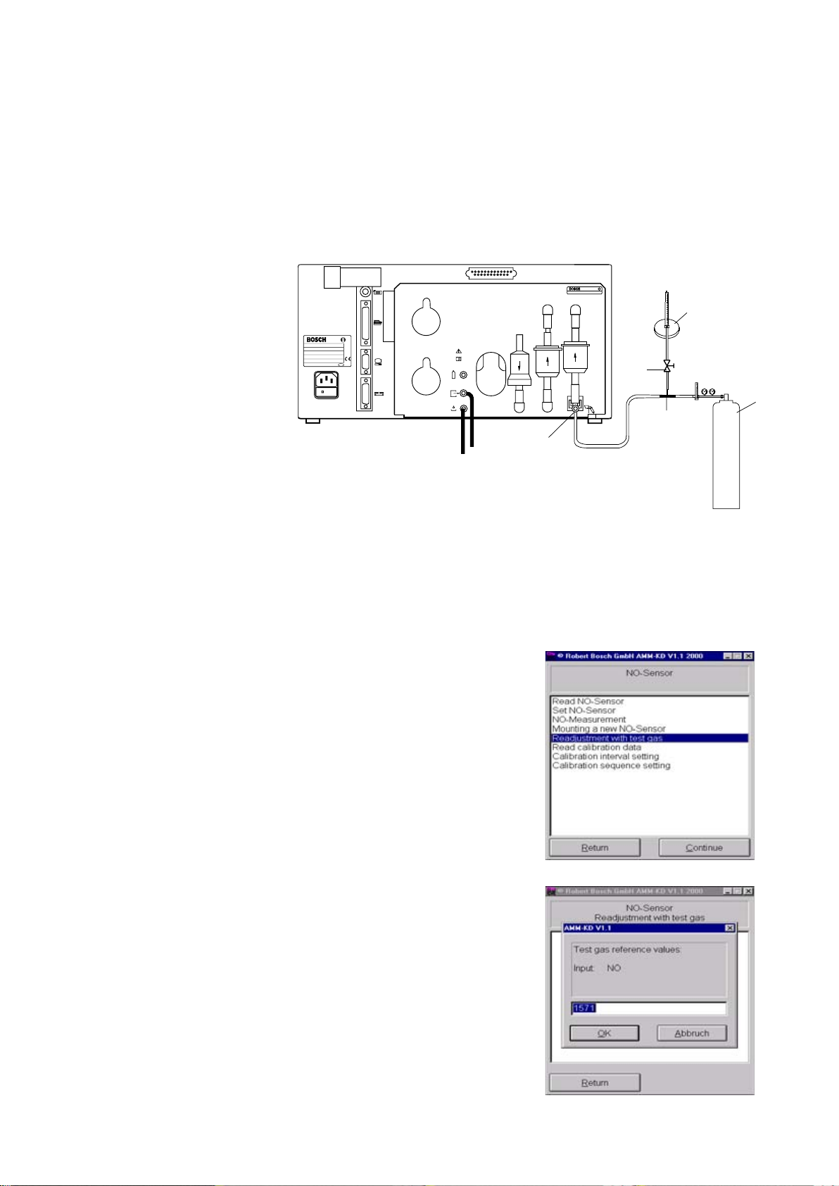
4.12.5 Readjustment with test gas i To calibrate the NO measuring sensor you will require a calibrating gas with the following composition:
From 1000 to 5000 ppm NO in nitrogen (N).
The electrochemical measuring sensor must be recalibrated at regular intervals. Only in
this way can measuring accuracy be reliably maintained. The recalibration process also
allows faulty NO measuring sensors to be detected.
Before commencing recalibration, connect the calibrating-gas bottle as shown in the
illustration below. Connect the calibrating-gas connection to the test-gas inlet.
Best. Nr. 1687 022 768 FD xxx
Best.- Nr.
Typ
Geräte - Nr.
FD U ( V )
P ( W ) F ( Hz )
Made in Germany
GF 3 GF 2
AF 1
O
2
088
cal
459737/25Ha
3
5
2
4
NO
1
1 Calibrating-gas bottle
2 Flow meter (rotameter)
3 Shutoff valve
4 Tee
5 Test-gas inlet
Start recalibration with E or by doubleclicking the mouse.
Using the keyboard, enter the calibratinggas value in ppm NO.
i If the calibrating-gas value is stated
3
on the certificate in mg/m
you must
convert this value to ppm.
The formula required for conversion
is:
Calibrating-gas value x 0.737.
Example:
3
2179 mg/m
= 1606 ppm NO
28
Confirm your entry with E or by clicking
OK.
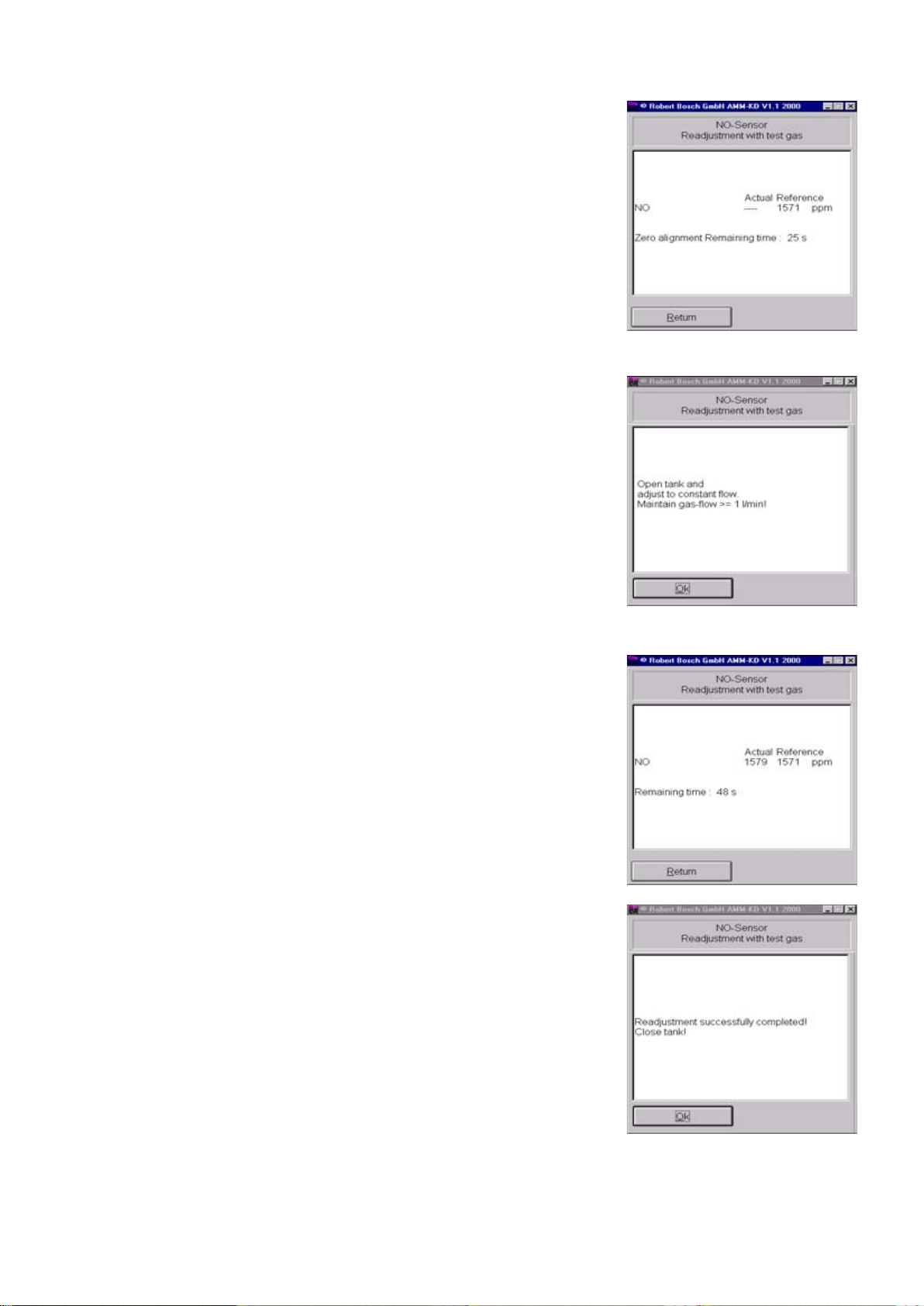
4.12.5 Readjustment with test gas ! Do not yet open the gas bottle!
The BEA performs zero calibration.
Allow calibrating gas to flow through the
BEA in line with the instructions on
screen.
Open the calibrating-gas bottle sufficiently to allow some calibrating gas to continually flow out through the rotameter, even
with the pump running (pressure-less calibration).
i The NO measuring sensor is very
sluggish. An "advance flow" through
the NO measuring sensor is therefore
necessary.
After this flow, confirm with E or by
clicking OK.
The remaining flow time is displayed.
Once recalibration has successfully been
completed, close the calibrating-gas bottle.
End recalibration by pressing E or by
clicking OK.
! If you have recalibrated the NO
measuring sensor because you have
just installed a new one, you must
also proceed according to the
instructions in Section 4.12.4,
Calibration of a new NO measuring
sensor.
29
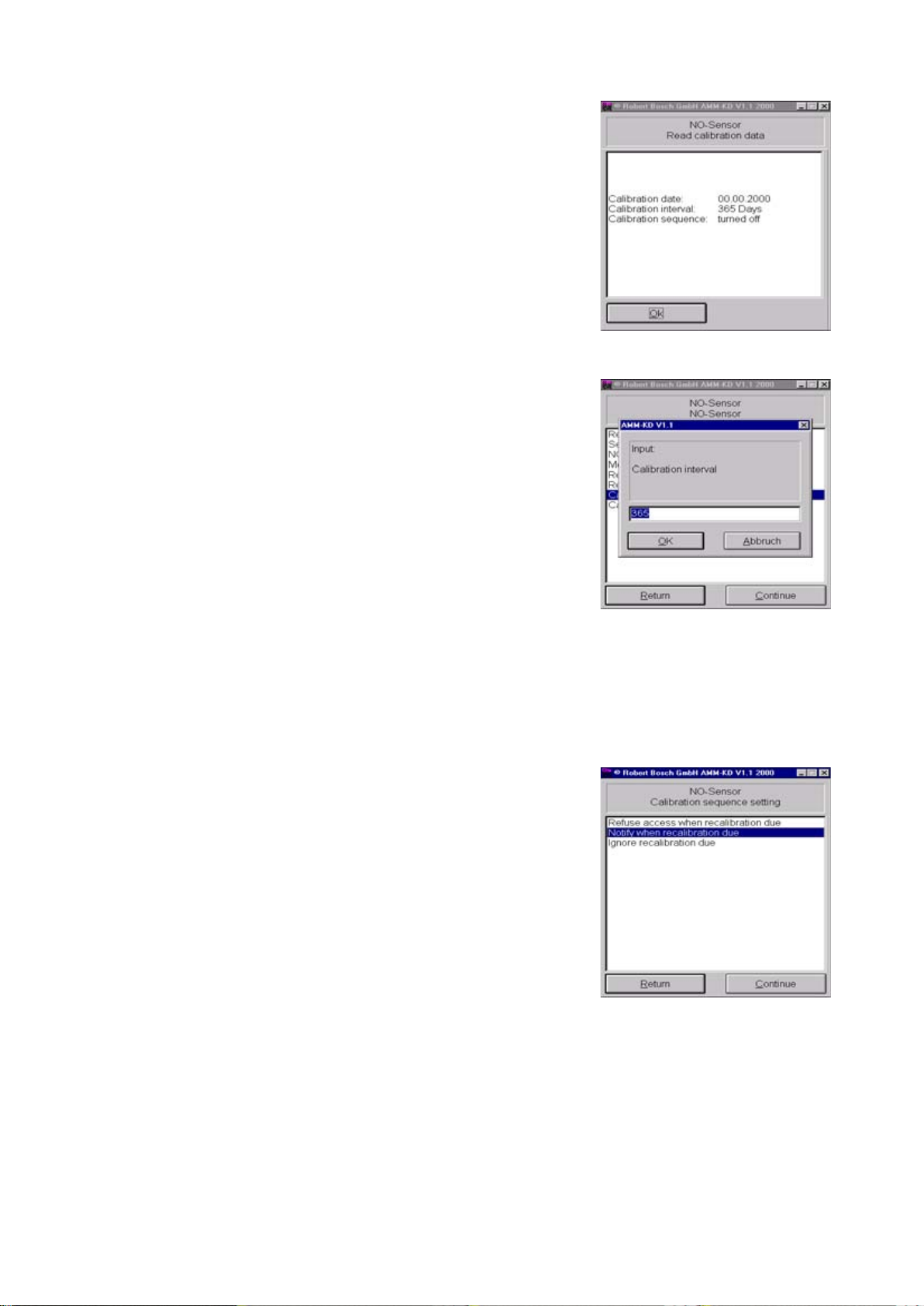
4.12.6 Read calibration data
The following data are read out in this
menu:
Calibration date
Date of next calibration.
Calibration interval
Interval before recalibration in days.
Calibration sequence
Reaction after the calibration interval has
elapsed (Sec. 4.12.8).
4.12.7 Calibration interval setting
4.12.8 Calibration sequence setting
i To access the Set calibration interval
menu, set the Service switch on the
test computer PCB to On.
In this menu, enter the number of days
after which the NO measuring sensor
must be recalibrated.
Enter the number of days using the keyboard.
Confirm your entry with E or by clicking
OK.
The OK window is displayed for 1 s.
This menu enables you to define how the
BEA should react once the calibration
interval has elapsed.
You can choose between the following
options:
Refuse access when recalibration
due:
Once the calibration interval has elapsed,
the BEA is disabled and displays a
message.
The BEA is only ready for measurement
once more after the NO measuring sensor
has been successfully recalibrated.
30
Notify when recalibration due:
Once the calibration interval has elapsed,
the BEA displays a message but remains
ready for measurement.
Ignore recalibration due
No message appears and the BEA
remains ready for measurement.
 Loading...