

Bosch CA, BC Installation, Operation And Maintenance Manual
CA Model
Installation, Operation and Maintenance Manual
970-293 (2014/06)
2 | Contents
Contents
Console Model
Model Nomenclature ...............................................2
Introduction: ............................................................3
Safety Considerations:.............................................3
Initial Inspection, Moving And Storage: ...................3
Installation: ..............................................................3
Piping: ......................................................................4
Condensate Piping:..................................................4
Hose Kits:.................................................................4
Electrical: .................................................................4
Cooling Tower/Boiler Applications: .........................4
Earth Coupled Systems: ..........................................5
Maintenance: ...........................................................5
System Checkout: ....................................................5
Unit Start-Up: ...........................................................5
Unit Protection Module (Upm) ................................6
Power Random Start Up ..........................................6
Y Call ........................................................................6
High And Low Pressure Protection ..........................6
Ground .....................................................................7
Dip Switch Settings .................................................7
Freeze Protection .....................................................7
Brownout Protection ...............................................8
Condensation Overow ...........................................8
Upm Sequence Of Operation (Soo) Flow Chart ......9
Wiring Diagrams ....................................................10
Operating Temperatures & Pressures Consoles ....13
Unit Check-Out Sheet ............................................15
Cuc Solid State ......................................................16
Freeze Sensor ..........................................................6
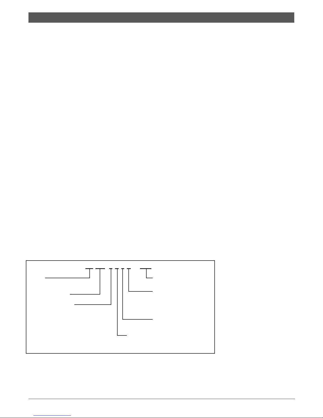
MODEL NOMENCLATURE
CA 012 - 1 U L C - XXX
SERIES:
CA - R-410A Refrigerant Slope Top
NOMINAL CAPACITY:
VOLTAGE DESIGNATION:
0 - 115/1/60
1 - 208/1/60 & 230/1/60
2 - 265/1/60
CONTROLS:
U - Manual/Auto Change Over (Unit Mounted)
R - Remote Thermostat
NOT USED
HEAT EXCHANGER:
C - COPPER
N - CUPRO-NICKEL
WATER CONNECTION LOCATION
L - LEFT
R - RIGHT
970-293 (2014/06) Subject to change without prior notice CA Series
3 | EP Series
Console Model
Introduction | 3
INTRODUCTION:
The console water source heat pumps are designed for
use as decentralized room terminals that are eld
connected to a closed- circuit piping loop within a
structure. Typically these units are installed in perimeter
zones and are ideal for installations where ducted
systems are impractical.
All units are designed for boiler/tower systems
geothermal closed loop applications and can operate
with uid temperatures as low as 25°F in heating and as
high as 110°F in cooling. Units are available in 3/4, 1,
1-1/4 and 1-1/2 tons nominal capacity in cooling. Refer
to the unit specication sheet for precise performance
gures at various entering air and water conditions.
NOTE: Console units are designed for indoor
installation in the conditioned space only. Do
not install outdoors, in attics or in any other
location that would subject the unit to extreme
temperature or humidity or to corrosive
environments. Doing so will inhibit
performance, reliability and service life of the
unit.
SAFETY CONSIDERATIONS:
Installation and servicing of this system can be
hazardous due to system pressure, electrical
components and moving par ts. Only trained and
qualied service personnel should install and service
this equipment. Untrained personnel can per form basic
maintenance such as cleaning coils/cabinet or replacing
lters.
WARNING: Before per forming service or
maintenance operations on system, turn off
main power to unit. On units with unit mounted
controls, the On/Off switch DOES NOT
disconnect the unit from main power. High
voltage components or moving parts can
cause injury or death.
When working on this equipment, always observe
precautions described in the literature, tags and labels
attached to the unit. Follow all safety codes. Wear safety
glasses and work gloves. Use a quenching cloth for
brazing operations and place a re extinguisher close to
the work area.
This unit is designed to be operated with the cabinet,
sub base and lter in place. Never operate unit without
the cabinet and lter in place or with open access
panels. Doing so can expose the operator to hazardous
voltage and moving parts and can damage the
equipment.
INITIAL INSPECTION, MOVING AND
STORAGE:
Inspect the carton or packaging of each console unit as
it is received at the job site and before signing the freight
bill. Note any damage or shortage on all copies of the
freight bill. Concealed damage must be reported to the
carrier within 24 hours of receipt.
Unit wiring diagrams and Installation/Operation
manuals are provided with each unit. Read these
manuals prior to star t up to become familiar with the
unit and its operation.
Note that an Installation/start-up checklist is
provided at the end of this manual to
encourage thorough unit check- out at
start-up.
Take care when moving the unit as most of the unit’s
weight is located on the left (compressor) end. Always
store and move unit in an upright position. Take care to
protect the unit cabinet and sub base when moving or
storing. Never move or lift unit by its water connections.
If the equipment is not needed for immediate
installation, it should be stored in its original packaging
in a clean, dry area. Units must be moved and stored in
an upright position, never lay the unit on it’s side. When
storing, do not stack units.
INSTALLATION:
Before installing the unit, examine each pipe, tting and
valve; remove any dirt or debris found on or in these
components. Use care when installing the system
components to avoid damage to the cabinet nish or
chassis.
1. After removing the console unit from its packaging
remove the cabinet by removing the cabinet screws
on either side of the unit and lifting the cabinet off
the chassis. Set the cabinet aside and cover it (the
console unit ’s pack aging can be used for this
purpose).
2. Position the sub base directly on the nished oor.
Make sure the sub base is level (use shims if
necessary). The sub base has a frame that supports
the cabinet and may be secured to wall.
3. Position the chassis onto the sub base. Check and
align electrical, water and condensate connections
and secure to the sub base with 4 screws.
4. Before connecting the unit to water, make sure that
the loop has been properly ushed. After ushing
the system, connect piping or hoses to the proper
supply, return and condensate connections. Refer to
the piping section of this manual for more
information
970-293 (2014/06)CA Series Subject to change without prior notice

4 | Piping
Console Model
5. Make all necessary electrical connections to the unit.
Refer to the unit wiring diagram and the Electrical
section of this manual.
CAUTION: When making electrical
connections to the unit make sure that the
power is disconnected. Failure to do
disconnect power before connecting power
wiring to the unit can result in serious injury or
death and damage to the unit.
6. Make sure the unit’s washable lter is clean and
installed in the sub base. Also make sure that the
lter clip is in place.
7. Reinstall the unit cabinet via locating pins at the top
of the chassis and two screws in the unit sub base.
PIPING:
SUPPLY AND RETURN PIPING:
The following items should be adhered to in addition to
applicable piping codes.
• A drain valve at the base of each riser to enable
proper ushing of the system at startup and during
servicing.
• Shut-off/Isolation ball valves at the supply and return
connections and unions at each unit to permit proper
ow balancing and unit servicing.
• Strainers at the inlet of each circulating pump.
• Use of teon tape on threaded pipe ttings to
eliminate water leaks and insure against air entering
the system.
• Flexible hose connections between the unit and the
rigid system to eliminate the possibility of vibration
transmission through the piping.
• Insulation is not normally required on supply and
return piping for boiler tower installations except in
unheated sections or outdoor runs.
• Insulation is required for closed-loop geo-thermal
installations as loop temperatures may fall below the
dew point and can even fall below the freezing point
of water during heating season.
CONDENSATE PIPING:
Console units are designed with a blow-through
conguration in the air handling section. This means that
there is positive pressure at the unit drain pan and thus
trapping is not required. Condensate is routed from the
drain pan via a 5/8” non-pressure rated vinyl hose that is
located below the supply and return water connections.
Though horizontal runs of condensate piping are usually
too short to pose problems, horizontal runs should be
pitched at least 1 inch for every 10 feet of piping. Avoid
low spots or unpitched piping, as these areas can collect
sediment and eventually block condensate ow.
Always inspect both internal and external condensate
piping for kinks that could block condensate ow.
HOSE KITS:
When using optional hose kits follow the manufacturer’s
recommendations for installation. Never stretch or twist
hoses and never use hoses that show external wear or
damage or are suspected of having damage. Never
exceed the manufacturer’s maximum working pressure
recommendations.
ELECTRICAL:
CAUTION: Use only copper conductors for
eld installed electrical wiring. Always make
sure that the power disconnect is open before
per forming service on the unit’s electrical
circuits.
Field wiring must comply with local and national re,
safety and electrical codes. Power to the unit must be
within the operating voltage range indicated on the unit
chassis nameplate or the performance data sheet.
Properly sized fuses or HACR breakers must be installed
for branch circuit protection. See unit chassis name plate
for maximum size.
Each chassis is supplied with a 2 x 4 junction box for
power connection. Inside this box there are 2 pigtail
leads for power wiring. The eld ground is to be
connected to the ground connection on the junction box.
On remote thermostat and master/slave units there are
also 5 position terminal blocks for low voltage thermostat
or slave unit connection. On remote thermostat units,
connect the thermostat wires to the low voltage terminal
block. On master/slave units connect the thermostat to
the “Master ” terminal block of the lead unit and the
“Slave” terminal block to the “Master ” terminal block of
the next unit, daisy chaining the units together as
required. Note that there is no limit to the number of
units that can be connected together in this manner as
each unit provides it’s own low voltage power supply.
NOTE: All 208/230 volt (-1 voltage code) units
are factory wired to 230 volts unless ordered
other wise. In 208 voltage applications the
transformer wiring may need to be switched
from the 230 volt tap to the 208 volt tap. Cap
all unused leads.
COOLING TOWER/BOILER
APPLICATIONS:
The cooling tower and boiler water loop temperature is
usually maintained between 50°F and 100°F to assure
adequate cooling and heating performance.
In the cooling mode, heat is rejected from the console
unit into the water loop. A cooling tower provides
evaporative cooling to the loop water thus maintaining a
constant supply water temperature to the unit. When
970-293 (2014/06) Subject to change without prior notice CA Series

5 | EP Series
Console Model
Earth Coupled Systems | 5
utilizing open cooling towers chemical water treatment
is mandatory to ensure the water is free from corrosive
elements. A secondary heat exchanger may also be used
between the unit and the cooling tower water. In closed
loop systems such as this it is imperative that all air be
removed from the closed side of the system to insure
against fouling of the heat pump water-to-refrigerant
heat exchanger.
In the heating mode, heat is absorbed from the loop by
the console unit. A boiler may be used to maintain the
loop at the desired temperature.
No unit should be connected to the supply or return
piping until the water system has been completely
cleaned and ushed to remove any dirt, piping chips or
other foreign material. Supply and return hoses should
be connected together during this process to ensure the
entire system is properly ushed. After the cleaning and
ushing has taken place the unit may be connected to
the water loop and should have all valves wide open.
EARTH COUPLED SYSTEMS:
Closed loop and pond applications require specialized
design knowledge. No attempt at these installations
should be made unless the contractor has received
specialized training.
Anti freeze solutions are utilized when low evaporating
conditions are expected to occur (I.E.: low loop
temperatures in heating). Typical temperatures are 30°F
uid temperature in heating and 100°F in cooling.
MAINTENANCE:
1. Filter changes or cleanings are required at regular
intervals. The time period between lter changes will
depend upon type of environment the equipment is
used in. In a single family home, that is not under
construction, changing or cleaning the lter every 60
days is sufcient. I n other applications, such as
motels, where daily vacuuming procedures a large
amount of lint, lter changes may need to be as
frequent as biweekly.
2. An annual “checkup” is recommended by a licensed
refrigeration mechanic. Recording the performance
measurements of volts,amps, and water temperature
differences (both heating and cooling) is
recommended. This data should be compared to the
information on the unit’s data plate and the data
taken at the original startup of the equipment.
3. Lubrication of the blower motor is not required.
4. The condensate drain should be checked annually by
cleaning or ushing to insure proper drainage.
5. Periodic lockouts almost always are caused by air or
water ow problems. The lockout (shut down) of the
unit is a normal protective measure in the design of
the equipment. If continual lockouts occur call a
mechanic immediately and have them check for:
water ow problems, water temperature problems,
air ow problems or air temperature problems. Use of
the pressure and temperature charts for the unit may
be required to properly determine the cause.
SYSTEM CHECKOUT:
• After completing the installation, and before
energizing the unit, the following system checks
should be made:
• Verify that the supply voltage to the heat pump is in
accordance with the nameplate ratings.
• Make sure that all electrical connections are tight and
secure.
• Check the electrical fusing and wiring for the correct
size.
• Verify that the low voltage wiring bet ween the
thermostat and the unit is correct.
• Verify that the water piping is complete and correct.
• Check that the water ow is correct, and adjust if
necessary.
• Check the blower for free rotation, and that it is
secured to the shaft.
• Verify that vibration isolation has been provided.
• Unit is serviceable. Be certain that all access panels
are secured in place.
UNIT START-UP:
1. Set the thermostat to the highest setting.
2. Set the thermostat system switch to “COOL”, and the
fan switch to the “AUTO” position. The reversing valve
solenoid should energize. The compressor and fan
should not run.
3. Reduce the thermostat setting approximately 5
degrees below the room temperature.
4. Verify the heat pump is operating in the cooling
mode.
5. Turn the thermostat system switch to the “OFF”
position. The unit should stop running and the
reversing valve should de-energize.
6. Leave the unit off for approximately (5) minutes to
allow for system equalization.
7. Turn the thermostat to the lowest setting.
8. Set the thermostat switch to “HEAT”.
9. Increase the thermostat setting approximately 5
degrees above the room temperature.
10. Verify the heat pump is operating in the heating
mode.
11. Set the thermostat to maintain the desired space
temperature.
12. Check for vibrations, leaks, etc...
970-293 (2014/06)CA Series Subject to change without prior notice
6 | Freeze Sensor
Console Model
FREEZE SENSOR
This is optional and can be set to ignore or monitor a
freeze sensor. There are 2 congurable freeze points,
30°F and 15°F. The unit will enter a soft lock out until the
temperature climbs above the set point and the anti-short
cycle time delay has expired. The freeze sensor may not
provide protection in the case of loss of ow in the
heating mode. A ow switch or pressure differential
switch is recommended to prevent unit operation in case
of loss of ow.
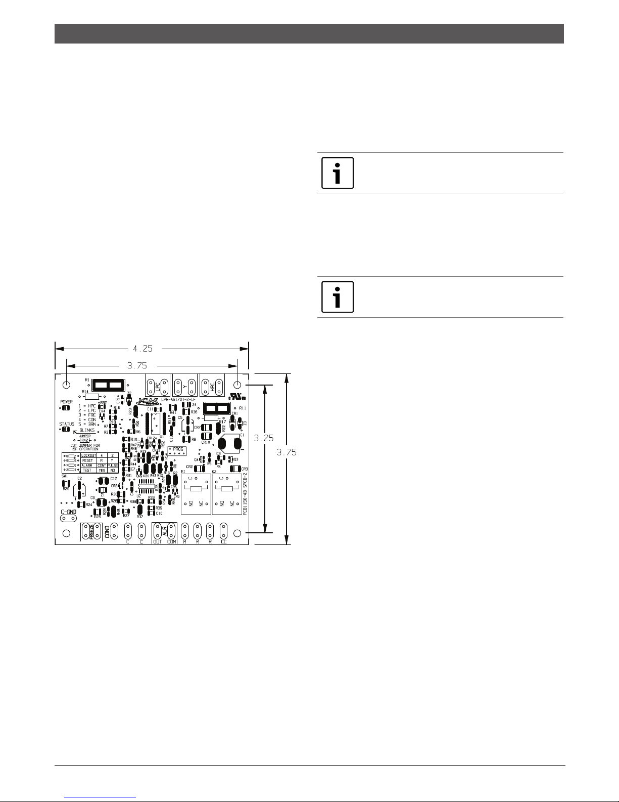
UNIT PROTECTION MODULE (UPM)
The Unit Protection Module (UPM) as shown in gure 1, is
a printed circuit board (PCB) that inter faces with the
thermostat or the digital direct controller.
The main purpose of this device is to protect the
compressors by monitoring the different states of
switches and sensors of each refrigerant circuit, this
device provides time delays and protects the unit against
freezing of the water and refrigerant heat exchangers as
well as condensate overow when the appropriate
sensors are installed (Figure 1).
If the controller has been completely powered down for
more than 28 milliseconds, a random delay is initiated
typically the unit will start between the time range of 270
and 300 seconds, this only if the controller is set to
normal operation (test switch set to NO).
In order for the random sequence to initiate the unit
power must be removed completely.
IMPORTANT: If the board is set to “ TEST ”
mode through the “ TEST ” DIP switch SW1
delay will be 10 seconds.
ANTI SHORT CYCLE DELAY
This feature protects the compressor short cycling if the
Y call is set and removed.
The anti short cycle delay is 300sec delay on break during
normal operation.
NOTE: If the board is set to test mode through
the “ TEST ” DIP switch the delay will be 5
seconds.
Y CALL
The UPM will energize the compressor’s output (CC) in
an event of a “Y” call from a thermostat or controller
(after the random start up and/or the anti short cycle
delays have elapsed). Y input terminal must be energized
with a 24 VAC signal.
HIGH AND LOW PRESSURE PROTECTION
The UPM monitors the state of the High and Low pressure
Switch inputs of each refrigerant circuit, HPC and LPC on
the board respectively, these switches must be closed in
order for the controller to energize the compressor output
(CC). The CC output will only be energized when the
switches are closed and the anti short cycle (and /or
random start up when applicable) has expired.
HIGH PRESSURE PROTECTION
If the HPC switch is open upon a Y call the UPM will not
Figure 1—Refer to unit wiring diagram for
connection details
Alarm output is Normally Open (NO) dry contact. If 24
VAC output is needed R must be wired to the ALR- COM
terminal; 24VAC will be available on the ALR-OUT terminal
when the unit is in alarm condition. If pulse is selected
the alarm output will be pulsed.
POWER RANDOM START UP
This feature prevents multiple units sharing same
electrical circuit or network from starting at the same
time.
It assures that Heat Pumps sharing the same electrical
circuit do not demand high inrush currents
simultaneously when star ting back up after a power
failure.
970-293 (2014/06) Subject to change without prior notice CA Series
energize the CC output and therefore the compressor
will remain off, the fault LED will ash one (1) time for
the HPC and the alarm contact will remain off.
If the compressor is running in normal mode on a Y call
and the high pressure switch opens, the UPM will shut
down the compressor output and will keep it off until the
switch closes and the anti short cycle has expired. The
controller will keep track of the number of times the
switch opens, if within one (1) hour period the switch
opens the number of times set via the DIP switch the
controller will shut the compressor down and per form a
hard lockout condition under this condition the alarm
contact will be energized.
The UPM allows the user to congure the counts that the
HPC will be allowed to open within one hour before the
UPM per forms a hard lockout on the compressor. The
 Loading...