

Bosch AVENAR panel 8000 Datasheet
Fire Alarm Systems - AVENAR panel 8000
AVENAR panel 8000
u Completely modular fire panel, expandable up
to 32 loops, provides customized solutions for
medium to large size applications
u High resolution display with bright colors to
indicate alarms and events
u 8" touch pad with fixed and programmable
buttons, thus adaptable to the situation
The fire panel allows mixed operation of analog
addressable and conventional technology. It supports
connecting periphery in either stub or loop topologies.
Analog addressable fire detectors, manual call points,
signaling devices, inputs and outputs are identified
and managed by the fire panel as single elements. As
required by the building structure the peripherals are
grouped software wise in logical zones.
The completely modular designed fire panel uses
functional modules that are clicked in a slot on a rail.
The rail provides power and internal communication
to the functional modules. A wide range of functional
modules are available providing: addressable loops,
conventional zones, inputs and outputs, and
interfaces to various devices. The fire alarm panel can
be equipped with 46 functional modules, of which a
maximum of 32 can be analog addressable loop
modules. This results in a tailor-made fire panel
suitable for medium to large size applications.
Two different types of housings are available to
assemble the fire panel:
• Wall mount housing
• Frame mount housing
The slim wall mount housings are for mounting
directly to the wall. Frame mount housings require an
additional frame between the housing and the wall.
The frame lets space for e.g. cabling, media
converters, and larger batteries. Special installation
u Integrated Ethernet switch for networking and
interfaces to remote services, building
management and voice alarm systems
u Adaptable to local requirements and regulations
kits also allow installation in 19" racks. Both housing
types can be extended with up-to four housings to
increase the number slots for the functional modules.
The panel controller is the central component of the
fire panel. A color display shows all messages. The
touch screen is for operation of the entire system. The
user-friendly interface adapts to various situations.
This causes correct operation that is simple and clear
as well as targeted and intuitive.
Panels and keypads of the AVENAR series and of the
FPA-5000 series (MPC-xxxx-B and MPC-xxxx-C) can be
combined in one panel network using the Ethernet
and the CAN bus interfaces. The remote keypad is for
decentralized operation of the panel or of the panel
network.
Integration into large-scale systems can be done by an
Ethernet interface to the Bosch Hierarchy panel
(UGM) or to Building Integration System (BIS).
Integration into third party management systems is
possible with the availability of OPC server and
Software Development Kit.
A data interface enables monitoring and full control of
Bosch voice alarm systems. This makes the fire panel
a complete safety solution.
The fire panel is configured on a laptop using the
FSP-5000-RPS programming software. The
programming software enables further adaptation,
e.g. to country-specific requirements and regulations.
Fire Alarm Systems - AVENAR panel 8000
N
I
TUO
AUX3AUX+AUX2+AUX AUX5+-AUX6
+-
BM0
4
1
6
7
9
8
N
I
TUO
LSN 0 30 0 A
AUX1+-LSN 1
a-b+
AUX2+-LSN 2
a-b+
ZONE4
Störung
ZONE3
Störung
ZONE2
Störung
ZONE1
Störung
CZM0004A
AUX1+-OUT1+-IN1+-AUX2+-OUT2+-IN2
+-
AUX3+-OUT3+-IN3+-AUX4+-OUT4+-IN4
+-
ANI0016A
F2F1
NC1
NO1C1NC2
NO2
C2
FB1
+
-
FB2
+-
RELAIS2
Störung
RELAIS1
Störung
RMH0002A
5
2
3
2 | 10
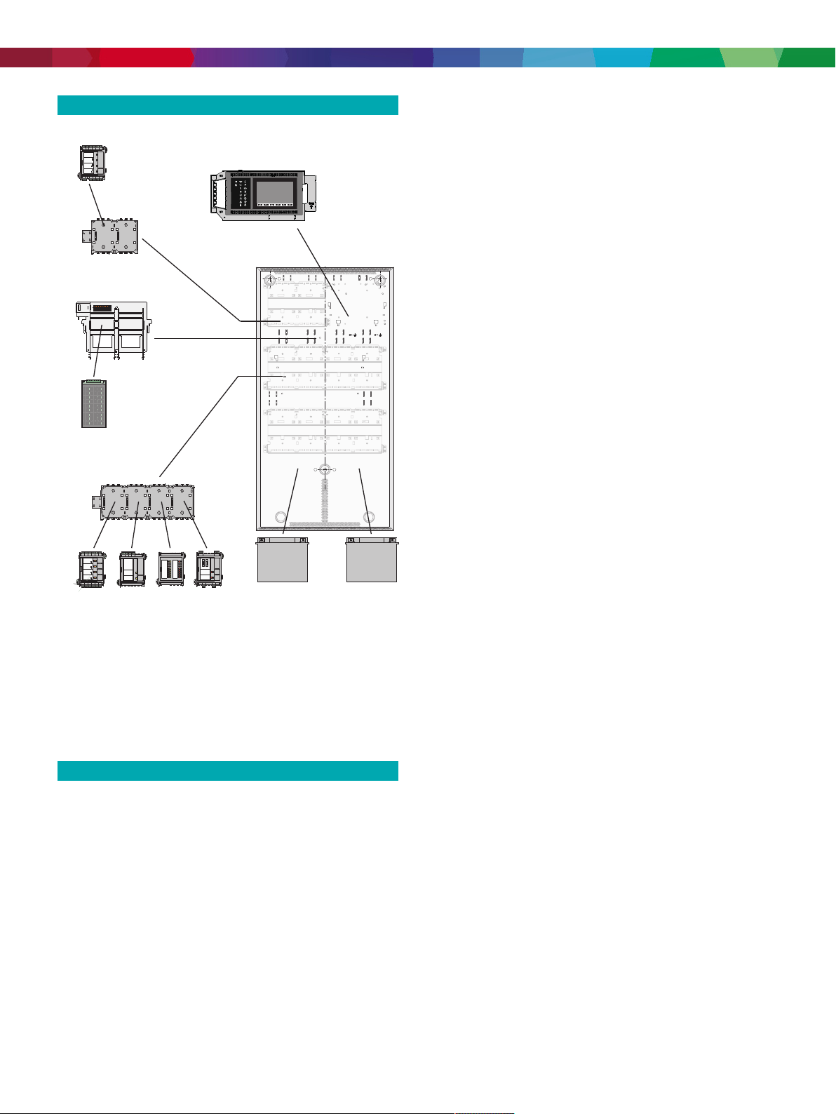
System overview
– Optional 19'' rack mounting kits
2. Panel controller
– Standard license: EN54 compliant fire detection
– Premium license: EN54 compliant fire detection,
various Ethernet interfaces and comfort features
– Panel redundancy: with additional panel con-
troller or with keypad
1. Functional modules
– Analogue addressable loops: standard or high
performance
– Conventional detection zones
– Conventional notification zones
– In- and output interfaces
– Serial communication interfaces
– LED annunciators
2. Power supply
– Battery capacity
– Battery autonomy: up-to 72 hours standby and
additional 30 minutes alarm condition
Alarm indication
All messages are shown on the display with a bright
color. The displayed messages contain the following
information:
• Message type
Fig.1:
Example configuration
1 Panel controller 2 BCM‑0000‑B Battery
Controller Module
3 Functional modules 4 PRS-0002-C Panel Rail Short
5 PRD 0004 A Panel Rail Long 6 Power supply bracket
7 Power supply unit 8 HBC 0010 A Panel Housing for
10 modules
9 Batteries
Functions
AVENAR panel 8000 is a completely modular fire panel
for medium to large size systems. All panel
components are separately available to provide
compete flexibility and tailor made solutions for
complex applications. Safety Systems Designer
supports the planning of the fire panel. The software
provides information about the size and number of
housings, the modules, interfaces various systems and
the energy balance calculation.
Depending on specific requirements, the planning
involves choosing from the following options:
1. Housing
– Frame mounting: slim design
– Wall mounting: additional space for cabling, me-
dia converters and larger batteries
• Type of the triggering element
• Description of the exact location of the triggering
element
• Logical zone and sub-address of the triggering
element
18Icon LEDs give continuous information about the
operating status of the panel or the system. A red icon
LED shows an alarm. A blinking yellow icon LED
shows a fault. A steady yellow icon LED shows a
disabled function. A green icon LED shows proper
operation.
Two status LEDs, one red and one yellow, are
programmable. The red one shows a self-defined
alarm. The yellow one shows a self-defined fault or
deactivation.
Additional annunciator modules, each with 16red and
16yellow LEDs are available to indicate a larger
number of self-defined alarms, faults or deactivations.
Operation and processing of messages
For operating the panel, an 8 inch touch pad as input
medium is put upon the display. There are 6 buttons
with fixed functionality as well as 3 programmable
function keys.
Examples for the assignment of the function keys:
• Set the panel controller to day mode, set the panel
controller to night mode
• Enable detection points or outputs, disable
detection points or outputs

Fire Alarm Systems - AVENAR panel 8000
3 | 10
• Set standard sensor sensitivity, set alternative
sensor sensitivity
Each function key has a virtual status indicator.
At any time, an operator with sufficient user rights can
control the function keys.
Overview of evacuation zones and outputs
At any time, the operator can get a clear overview of
each evacuation zone and of each output connected
to the fire protection equipment. Each zone and each
output is marked with a programmable text label and
a clearly distinctive color reflecting the state: Green
shows idle state, power is available. Red shows an
activation during fire alarm condition, and fuchsia an
activation without a fire alarm condition. Yellow shows
a fault or disabled state. An operator with sufficient
user rights is able to start the evacuation in selected
zones and activate outputs connected to the fire
protection equipment through the user interface.
Saving and printing messages
The history log keeps incoming alarms and events
internally. The history log has a capacity to store
10000 messages. The messages can be shown on the
display, and you can export the messages.
Additionally, you can connect a log printer via a serial
interface module for real-time printing incoming
messages.
Languages
The operator can change the language of the user
interface. A printed quick user guide for each language
is supplied with the package. Following languages are
included: English, German, Bulgarian, Croatian, Czech,
Danish, Dutch, Estonian, French, Greek, Hungarian,
Italian, Latvian, Lithuanian, Polish, Portuguese,
Romanian, Russian, Serbian, Slovak, Slovenian,
Spanish, Swedish and Turkish.
Licenses
The panel controller is delivered with a hard coded
software license. This software license is implemented
during production and cannot be modified, revoked or
transported. The license defines the maximum panel
network size and availability of certain features and
interfaces.
 Loading...