
Bosch Atino Service Manual

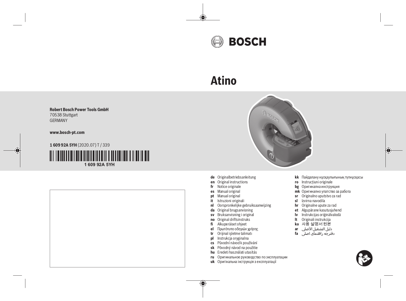
Atino

Robert Bosch Power Tools GmbH

70538 Stuttgart

GERMANY

www.bosch-pt.com

1 609 92A 5YH (2020.07) T / 339

1 609 92A 5YH


de

Originalbetriebsanleitung

kk

Пайдалану нұсқаулығының түпнұсқасы


en

Original instructions

ro

Instrucțiuni originale


fr

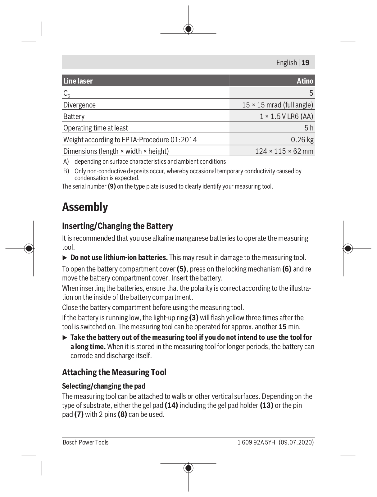
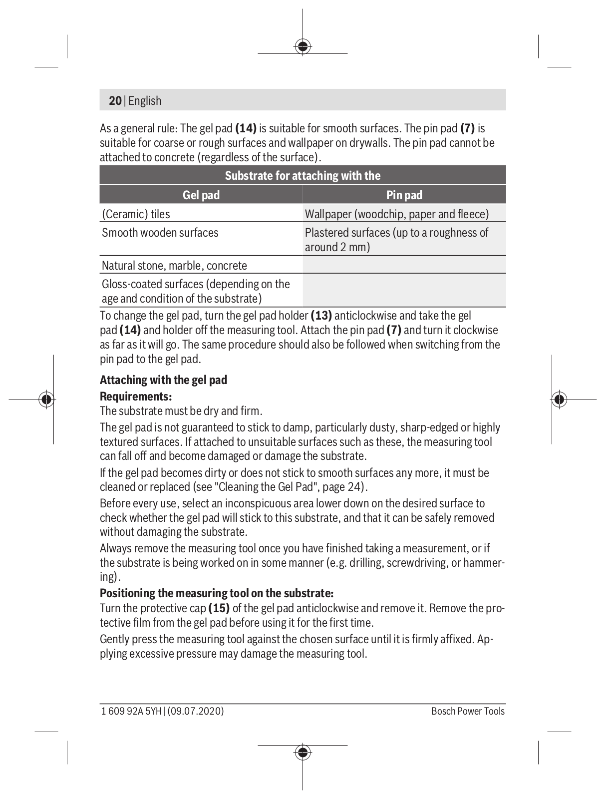
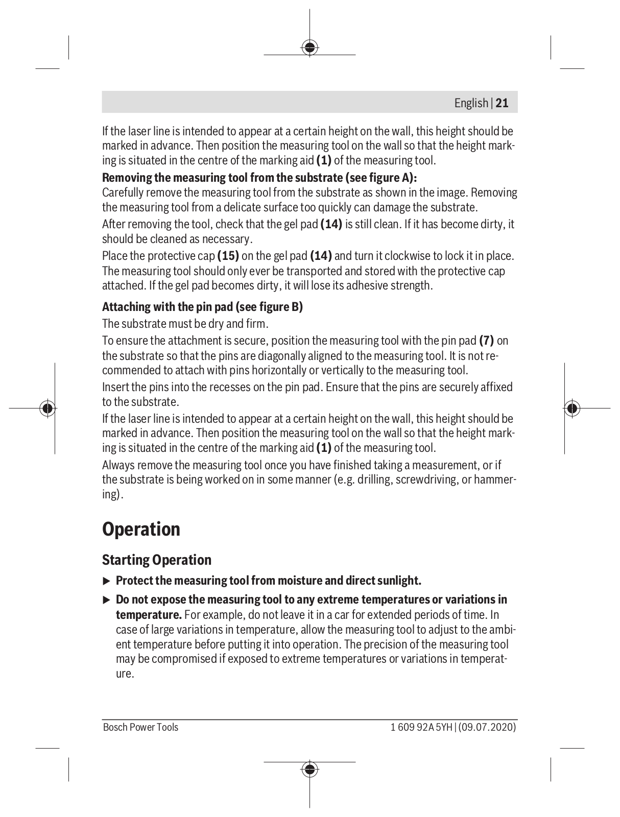
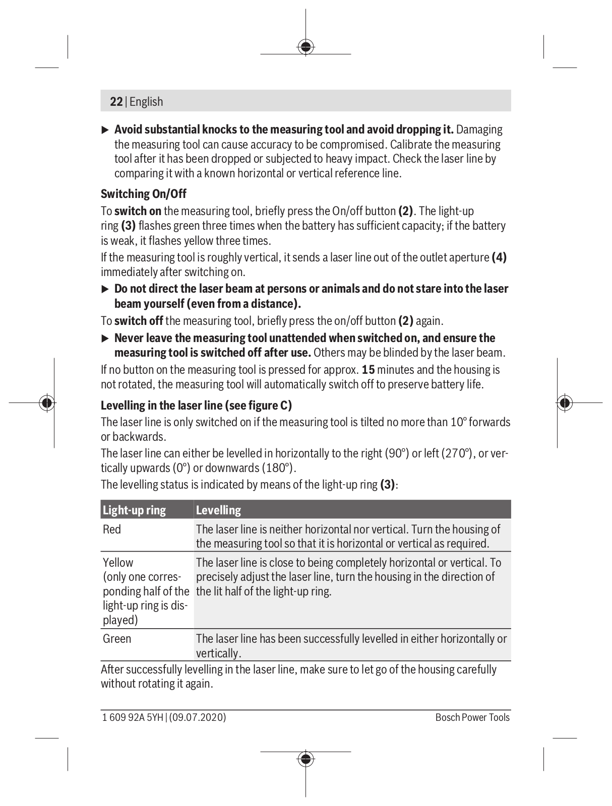
Notice originale

bg

Оригинална инструкция


es

Manual original

mk

Оригинално упатство за работа


pt

Manual original

sr

Originalno uputstvo za rad


it

Istruzioni originali

sl

Izvirna navodila


nl

Oorspronkelijke gebruiksaanwijzing

hr

Originalne upute za rad


da

Original brugsanvisning

et

Algupärane kasutusjuhend


sv

Bruksanvisning i original

lv

Instrukcijas oriģinālvalodā


no

Original driftsinstruks

lt

Originali instrukcija


fi

Alkuperäiset ohjeet

ko


el

Πρωτότυπο οδηγιών χρήσης

ar

يلصلأا ليغشتلا ليلد


tr

Orijinal işletme talimatı

fa

یلصا یامنهار هچرتفد


pl

Instrukcja oryginalna


cs

Původní návod k používání


sk

Pôvodný návod na použitie


hu

Eredeti használati utasítás


ru

Оригинальное руководство по эксплуатации


uk

Оригінальна інструкція з експлуатації


2 |

Deutsch . . . . . . . . . . . . . . . . . . . . . . . . . . . . . . . . . . . . .

. . . . Seite

6

English . . . . . . . . . . . . . . . . . . . . . . . . . . . . . . . . . . . . . . .

. . . .Page

16

Français. . . . . . . . . . . . . . . . . . . . . . . . . . . . . . . . . . . . . .

. . . .Page

26

Español . . . . . . . . . . . . . . . . . . . . . . . . . . . . . . . . . . . . . .

. . Página

37

Português . . . . . . . . . . . . . . . . . . . . . . . . . . . . . . . . . . . .

. . Página

47

Italiano . . . . . . . . . . . . . . . . . . . . . . . . . . . . . . . . . . . . . . .

. . Pagina

57

Nederlands . . . . . . . . . . . . . . . . . . . . . . . . . . . . . . . . . . .

. . Pagina

67

Dansk . . . . . . . . . . . . . . . . . . . . . . . . . . . . . . . . . . . . . . . .

. . . . Side

77

Svensk . . . . . . . . . . . . . . . . . . . . . . . . . . . . . . . . . . . . . . .

. . . Sidan

87

Norsk . . . . . . . . . . . . . . . . . . . . . . . . . . . . . . . . . . . . . . . .

. . . . Side

96

Suomi. . . . . . . . . . . . . . . . . . . . . . . . . . . . . . . . . . . . . . . .

. . . . Sivu

105

Ελληνικά . . . . . . . . . . . . . . . . . . . . . . . . . . . . . . . . . . . . .

. . Σελίδα

114

Türkçe . . . . . . . . . . . . . . . . . . . . . . . . . . . . . . . . . . . . . . .

. . . Sayfa

125

Polski . . . . . . . . . . . . . . . . . . . . . . . . . . . . . . . . . . . . . . . .

. . Strona

137

Čeština. . . . . . . . . . . . . . . . . . . . . . . . . . . . . . . . . . . . . . .

. Stránka

147

Slovenčina . . . . . . . . . . . . . . . . . . . . . . . . . . . . . . . . . . .

. Stránka

157

Magyar . . . . . . . . . . . . . . . . . . . . . . . . . . . . . . . . . . . . . . .

. . . Oldal

167

Русский. . . . . . . . . . . . . . . . . . . . . . . . . . . . . . . . . . . . .

Страница

177

Українська . . . . . . . . . . . . . . . . . . . . . . . . . . . . . . . . . . .

Сторінка

189

Қазақ . . . . . . . . . . . . . . . . . . . . . . . . . . . . . . . . . . . . . . . .

. . . . . Бет

200

Română . . . . . . . . . . . . . . . . . . . . . . . . . . . . . . . . . . . . . .

. . Pagina

212

Български. . . . . . . . . . . . . . . . . . . . . . . . . . . . . . . . . . .

Страница

222

Македонски . . . . . . . . . . . . . . . . . . . . . . . . . . . . . . . . .

Страница

232

Srpski. . . . . . . . . . . . . . . . . . . . . . . . . . . . . . . . . . . . . . . .

. . Strana

242

Slovenščina . . . . . . . . . . . . . . . . . . . . . . . . . . . . . . . . . .

. . . Stran

252

Hrvatski . . . . . . . . . . . . . . . . . . . . . . . . . . . . . . . . . . . . . .

Stranica

262

Eesti . . . . . . . . . . . . . . . . . . . . . . . . . . . . . . . . . . . . . . . . .

Lehekülg

271

Latviešu . . . . . . . . . . . . . . . . . . . . . . . . . . . . . . . . . . . . . .

Lappuse

280

Lietuvių k. . . . . . . . . . . . . . . . . . . . . . . . . . . . . . . . . . . . .

Puslapis

290

. . . . . . . . . . . . . . . . . . . . . . . . . . . . . . . . . . . . . .

. 299

يبرع . . . . . . . . . . . . . . . . . . . . . . . . . . . . . . . . . . . . . . . .

. ةحفصلا

309

یسراف . . . . . . . . . . . . . . . . . . . . . . . . . . . . . . . . . . . . . . .

. . هحفص 319

. . . . . . . . . . . . . . . . . . . . . . . . . . . . . . . . . . . . . . . . . . . . . . . .

I

1 609 92A 5YH | (09.07.2020)


Bosch Power Tools


Bosch Atino Service Manual

| 3

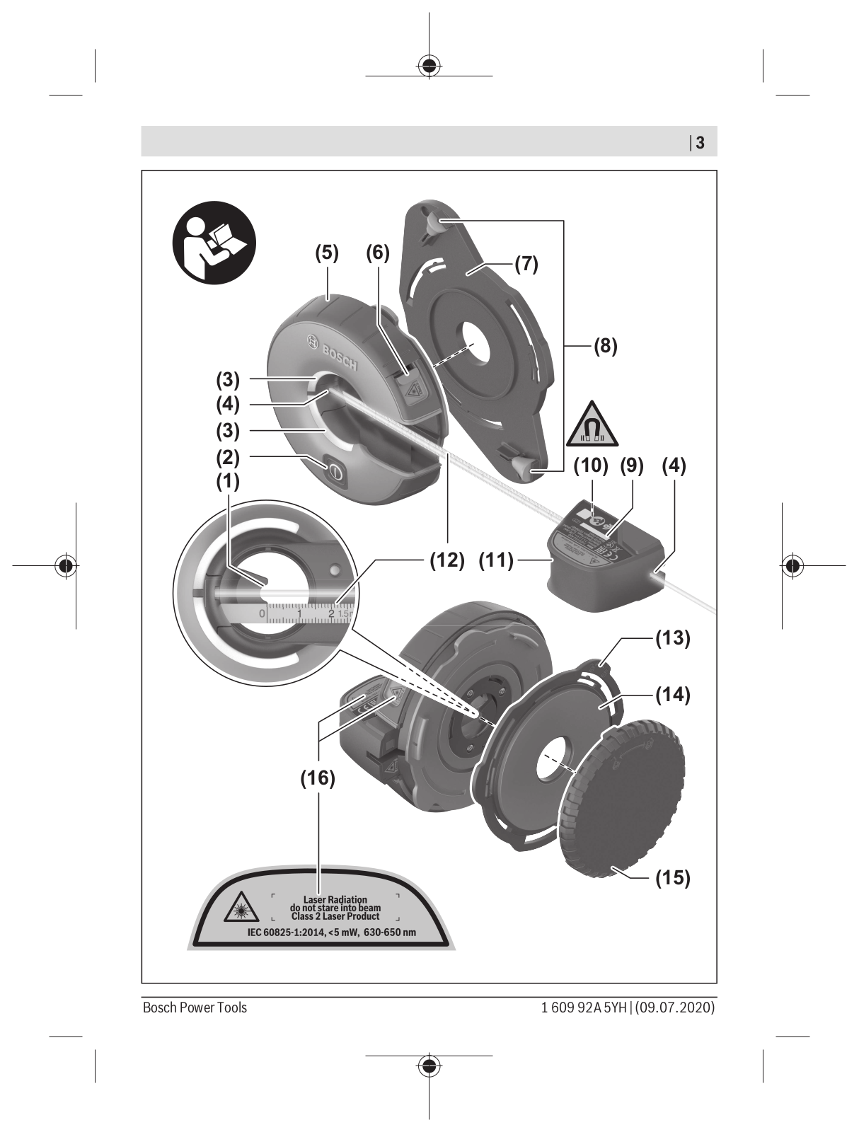
(5) (6)

(7)

(8)

(3)

(4)

(3)

(2)

(10)

(9)

(4)

(1)


(12) (11)

(13)

(14)

(16)

(15)

Bosch Power Tools


1 609 92A 5YH | (09.07.2020)


4 |

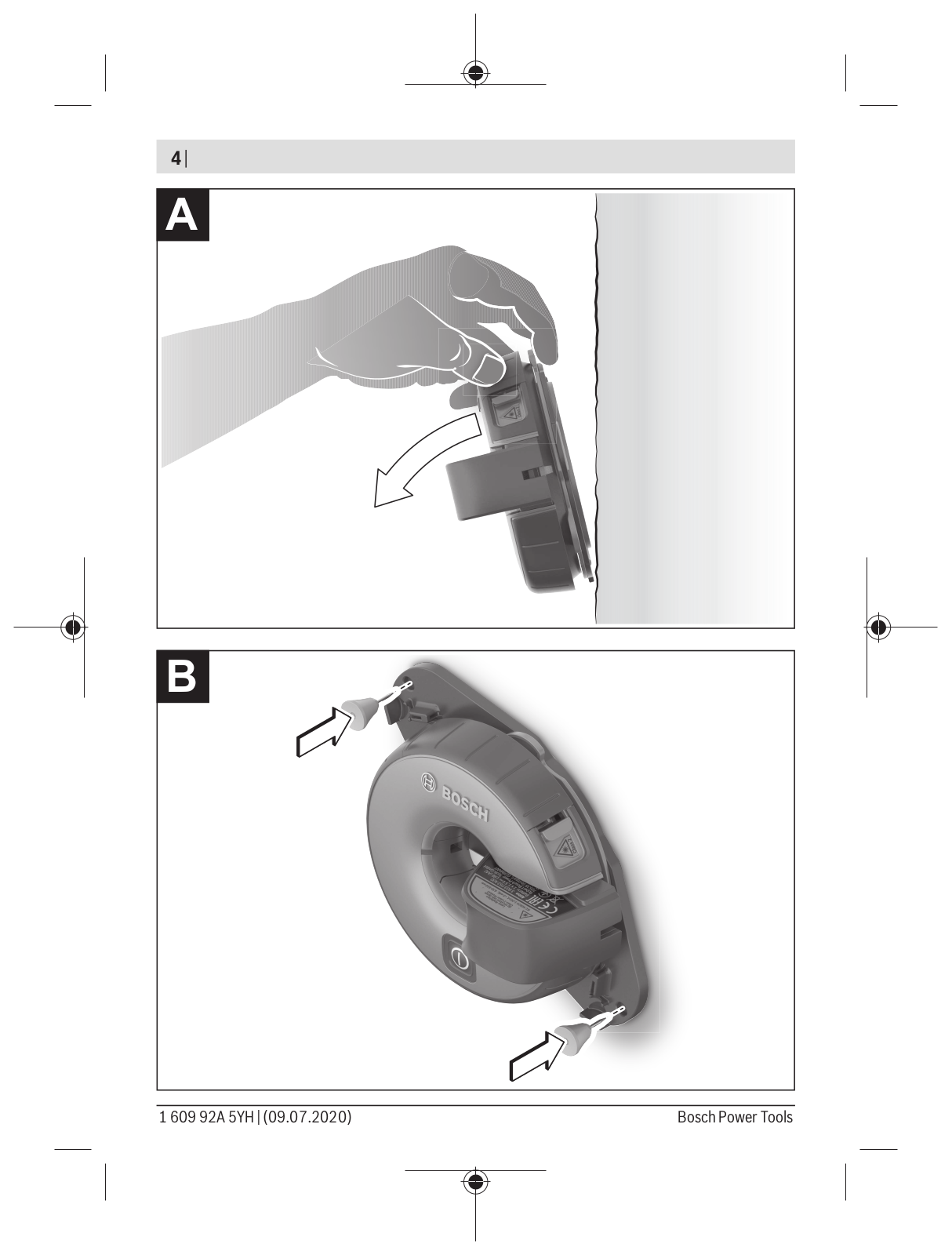
A

B

1 609 92A 5YH | (09.07.2020)


Bosch Power Tools


| 5

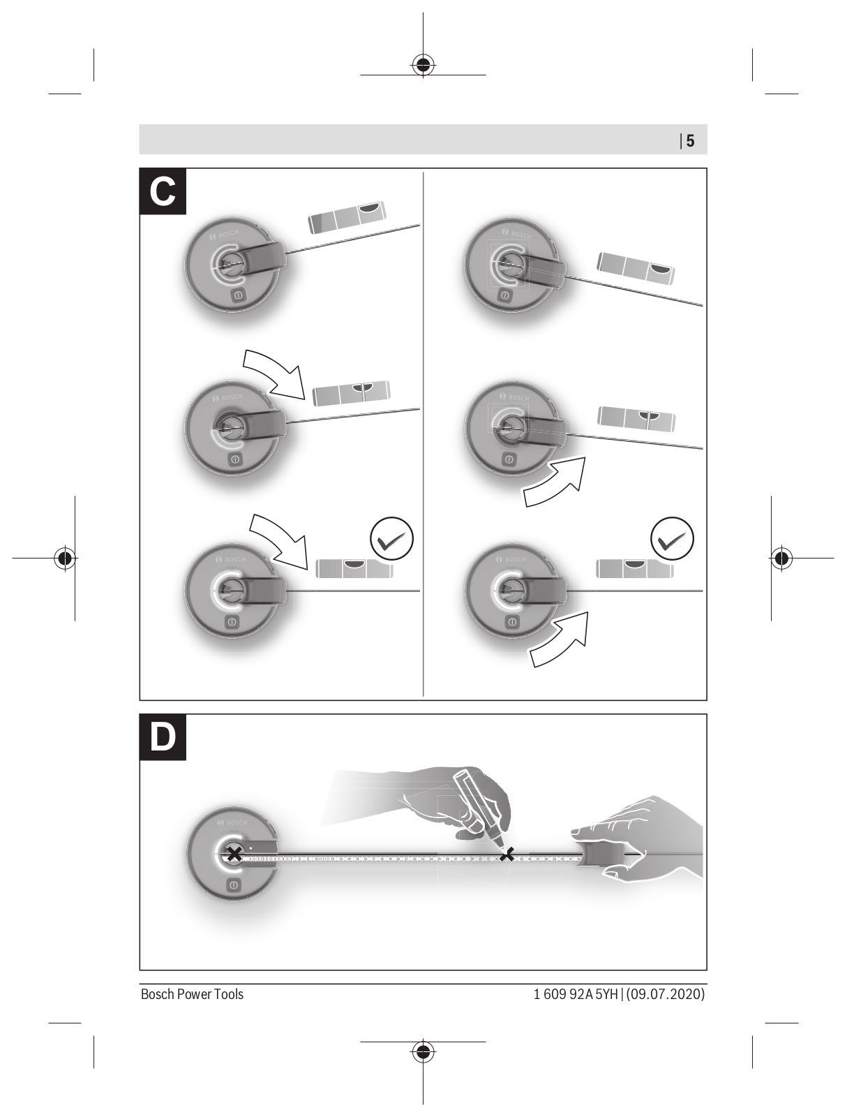
C

D

Bosch Power Tools


1 609 92A 5YH | (09.07.2020)


6 | Deutsch

Deutsch

Sicherheitshinweise

Sämtliche Anweisungen sind zu lesen und zu beachten, um mit dem Messwerkzeug gefahrlos und sicher zu arbeiten. Wenn das Messwerkzeug nicht entsprechend den vorliegenden Anweisungen verwendet wird, können die integrierten Schutzvorkehrungen im Messwerkzeug beeinträchtigt werden. Machen Sie Warn-

schilder am Messwerkzeug niemals unkenntlich. BEWAHREN SIE DIESE ANWEISUNGEN GUT AUF UND GEBEN SIE SIE BEI WEITERGABE DES MESSWERKZEUGS MIT.

uVorsicht – wenn andere als die hier angegebenen Bedienungsoder Justiereinrichtungen benutzt oder andere Verfahrensweisen ausgeführt werden, kann dies zu gefährlicher Strahlungsexposition führen.

uDas Messwerkzeug wird mit einem Laser-Warnschild ausgeliefert (in der Darstellung des Messwerkzeugs auf der Grafikseite gekennzeichnet).

uIst der Text des Laser-Warnschildes nicht in Ihrer Landessprache, dann überkleben Sie ihn vor der ersten Inbetriebnahme mit dem mitgelieferten Aufkleber in Ihrer Landessprache.

Richten Sie den Laserstrahl nicht auf Personen oder Tiere und bli-

cken Sie nicht selbst in den direkten oder reflektierten Laser-

strahl. Dadurch können Sie Personen blenden, Unfälle verursachen

oder das Auge schädigen.

uFalls Laserstrahlung ins Auge trifft, sind die Augen bewusst zu schließen und der Kopf sofort aus dem Strahl zu bewegen.

uNehmen Sie keine Änderungen an der Lasereinrichtung vor.

uVerwenden Sie die Laser-Sichtbrille nicht als Schutzbrille. Die Laser-Sichtbrille dient zum besseren Erkennen des Laserstrahls; sie schützt jedoch nicht vor der Laserstrahlung.

uVerwenden Sie die Laser-Sichtbrille nicht als Sonnenbrille oder im Straßenverkehr. Die Laser-Sichtbrille bietet keinen vollständigen UV-Schutz und vermindert die Farbwahrnehmung.

1 609 92A 5YH | (09.07.2020)


Bosch Power Tools


Deutsch | 7

uLassen Sie das Messwerkzeug nur von qualifiziertem Fachpersonal und nur mit Original-Ersatzteilen reparieren. Damit wird sichergestellt, dass die Sicherheit des Messwerkzeuges erhalten bleibt.

uLassen Sie Kinder das Laser-Messwerkzeug nicht unbeaufsichtigt benutzen. Sie könnten unbeabsichtigt Personen blenden.

uArbeiten Sie mit dem Messwerkzeug nicht in explosionsgefährdeter Umgebung, in der sich brennbare Flüssigkeiten, Gase oder Stäube befinden. Im Messwerkzeug können Funken erzeugt werden, die den Staub oder die Dämpfe entzünden.

Bringen Sie den Magnet nicht in die Nähe von Implantaten oder

sonstigen medizinischen Geräten, wie z.B. Herzschrittmacher

oder Insulinpumpe. Durch den Magnet wird ein Feld erzeugt, das die

Funktion von Implantaten oder medizinischen Geräten beeinträchti-

gen kann.

uHalten Sie das Messwerkzeug fern von magnetischen Datenträgern und magnetisch empfindlichen Geräten. Durch die Wirkung der Magnete kann es zu irreversiblen Datenverlusten kommen.

Produktund Leistungsbeschreibung

Bitte beachten Sie die Abbildungen im vorderen Teil der Betriebsanleitung.

Bestimmungsgemäßer Gebrauch

Das Messwerkzeug ist bestimmt zum Ermitteln und Überprüfen von waagerechten und senkrechten Linien.

Das Messwerkzeug ist zur Verwendung im Innenbereich geeignet.

Abgebildete Komponenten

Die Nummerierung der abgebildeten Komponenten bezieht sich auf die Darstellung des Messwerkzeugs auf der Grafikseite.

(1)Markierungshilfe

(2)Ein-/Aus-Taste

(3)Leuchtring

(4)Austrittsöffnung Laserstrahlung

(5)Batteriefachdeckel

(6)Arretierung des Batteriefachdeckels

(7)Pinpad

Bosch Power Tools


1 609 92A 5YH | (09.07.2020)


8 | Deutsch

(8)

Pin

(9)

Seriennummer

(10)

Magnet

(11)

Maßband-Gehäuse

(12)

Maßband

(13)

Halterung Gelpad

(14)

Gelpad

(15)

Schutzkappe Gelpad

(16)

Laser-Warnschild

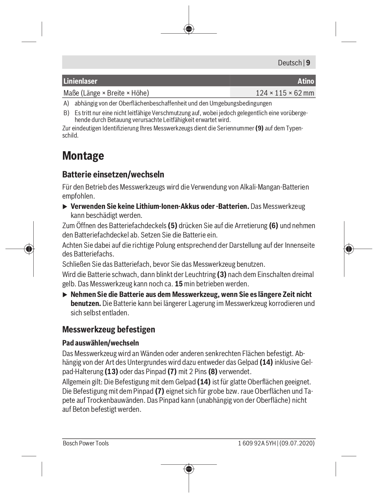
Technische Daten

Linienlaser

Atino

Sachnummer

3 603 F63 A..

Länge LaserlinieA)

1,7 m

Nivelliergenauigkeit der sichtbaren Laserlinie

±0,3°

Länge Maßband

1,5 m

Messgenauigkeit Maßband

±2 mm/m

Genauigkeitsklasse Maßband


Betriebstemperatur

+5 °C … +40 °C

Lagertemperatur

–20 °C … +70 °C

max. Einsatzhöhe über Bezugshöhe

2000 m

relative Luftfeuchte max.

90 %

Verschmutzungsgrad entsprechend IEC 61010-1

2B)

Laserklasse

2

Lasertyp

630−650 nm, < 5 mW

C6

5

Divergenz

15 × 15 mrad (Vollwinkel)

Batterie

1 × 1,5 V LR6 (AA)

Betriebsdauer mindestens

5 h

Gewicht entsprechend EPTA-Procedure 01:2014

0,26 kg

1 609 92A 5YH | (09.07.2020)


Bosch Power Tools


Deutsch | 9


Linienlaser

Atino

Maße (Länge × Breite × Höhe)

124 × 115 × 62 mm

A)abhängig von der Oberflächenbeschaffenheit und den Umgebungsbedingungen

B)Es tritt nur eine nicht leitfähige Verschmutzung auf, wobei jedoch gelegentlich eine vorübergehende durch Betauung verursachte Leitfähigkeit erwartet wird.

Zur eindeutigen Identifizierung Ihres Messwerkzeugs dient die Seriennummer (9) auf dem Typenschild.

Montage

Batterie einsetzen/wechseln

Für den Betrieb des Messwerkzeugs wird die Verwendung von Alkali-Mangan-Batterien

empfohlen.

uVerwenden Sie keine Lithium-Ionen-Akkus oder -Batterien. Das Messwerkzeug kann beschädigt werden.

Zum Öffnen des Batteriefachdeckels (5) drücken Sie auf die Arretierung (6) und nehmen den Batteriefachdeckel ab. Setzen Sie die Batterie ein.

Achten Sie dabei auf die richtige Polung entsprechend der Darstellung auf der Innenseite des Batteriefachs.

Schließen Sie das Batteriefach, bevor Sie das Messwerkzeug benutzen.

Wird die Batterie schwach, dann blinkt der Leuchtring (3) nach dem Einschalten dreimal gelb. Das Messwerkzeug kann noch ca. 15 min betrieben werden.

uNehmen Sie die Batterie aus dem Messwerkzeug, wenn Sie es längere Zeit nicht benutzen. Die Batterie kann bei längerer Lagerung im Messwerkzeug korrodieren und sich selbst entladen.

Messwerkzeug befestigen

Pad auswählen/wechseln

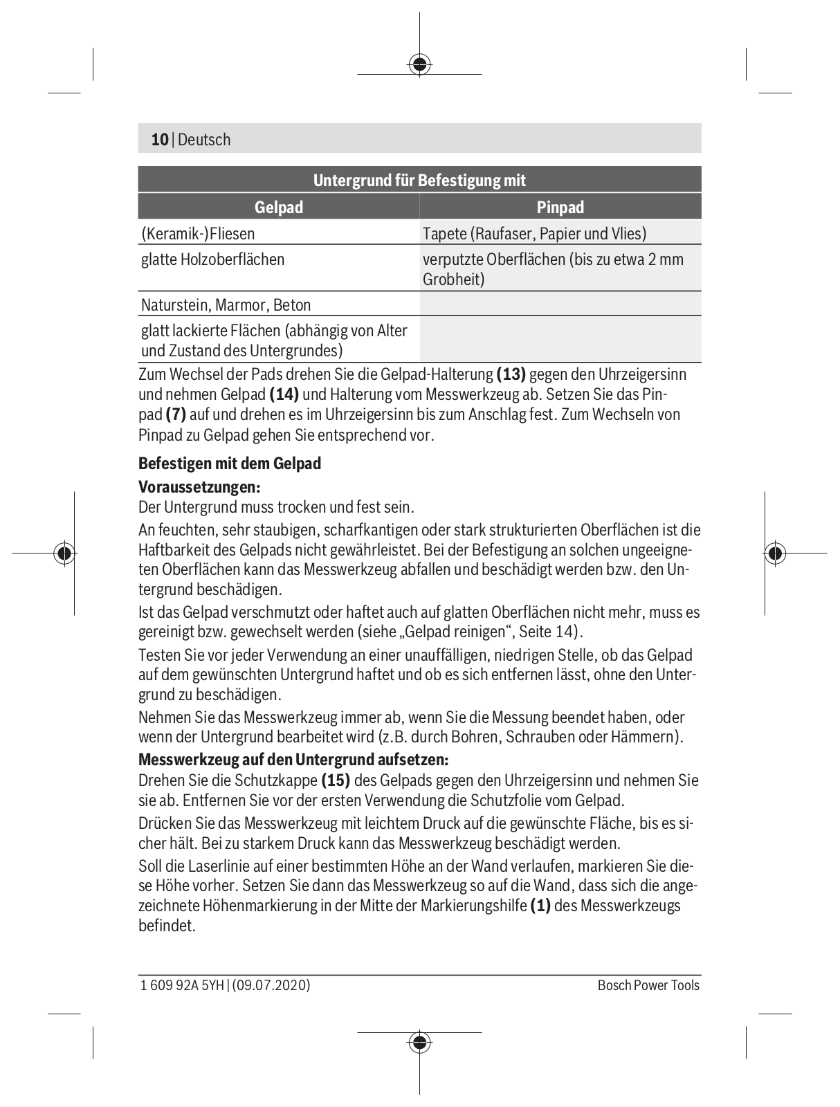
Das Messwerkzeug wird an Wänden oder anderen senkrechten Flächen befestigt. Abhängig von der Art des Untergrundes wird dazu entweder das Gelpad (14) inklusive Gel- pad-Halterung (13) oder das Pinpad (7) mit 2 Pins (8) verwendet.

Allgemein gilt: Die Befestigung mit dem Gelpad (14) ist für glatte Oberflächen geeignet. Die Befestigung mit dem Pinpad (7) eignet sich für grobe bzw. raue Oberflächen und Tapete auf Trockenbauwänden. Das Pinpad kann (unabhängig von der Oberfläche) nicht auf Beton befestigt werden.

Bosch Power Tools


1 609 92A 5YH | (09.07.2020)


10 | Deutsch


Untergrund für Befestigung mit

Gelpad


Pinpad

(Keramik-)Fliesen


Tapete (Raufaser, Papier und Vlies)

glatte Holzoberflächen


verputzte Oberflächen (bis zu etwa 2 mm


Grobheit)

Naturstein, Marmor, Beton


glatt lackierte Flächen (abhängig von Alter und Zustand des Untergrundes)

Zum Wechsel der Pads drehen Sie die Gelpad-Halterung (13) gegen den Uhrzeigersinn und nehmen Gelpad (14) und Halterung vom Messwerkzeug ab. Setzen Sie das Pinpad (7) auf und drehen es im Uhrzeigersinn bis zum Anschlag fest. Zum Wechseln von Pinpad zu Gelpad gehen Sie entsprechend vor.

Befestigen mit dem Gelpad

Voraussetzungen:

Der Untergrund muss trocken und fest sein.

An feuchten, sehr staubigen, scharfkantigen oder stark strukturierten Oberflächen ist die Haftbarkeit des Gelpads nicht gewährleistet. Bei der Befestigung an solchen ungeeigneten Oberflächen kann das Messwerkzeug abfallen und beschädigt werden bzw. den Untergrund beschädigen.

Ist das Gelpad verschmutzt oder haftet auch auf glatten Oberflächen nicht mehr, muss es gereinigt bzw. gewechselt werden (siehe „Gelpad reinigen“, Seite 14).

Testen Sie vor jeder Verwendung an einer unauffälligen, niedrigen Stelle, ob das Gelpad auf dem gewünschten Untergrund haftet und ob es sich entfernen lässt, ohne den Untergrund zu beschädigen.

Nehmen Sie das Messwerkzeug immer ab, wenn Sie die Messung beendet haben, oder wenn der Untergrund bearbeitet wird (z.B. durch Bohren, Schrauben oder Hämmern).

Messwerkzeug auf den Untergrund aufsetzen:

Drehen Sie die Schutzkappe (15) des Gelpads gegen den Uhrzeigersinn und nehmen Sie sie ab. Entfernen Sie vor der ersten Verwendung die Schutzfolie vom Gelpad.

Drücken Sie das Messwerkzeug mit leichtem Druck auf die gewünschte Fläche, bis es sicher hält. Bei zu starkem Druck kann das Messwerkzeug beschädigt werden.

Soll die Laserlinie auf einer bestimmten Höhe an der Wand verlaufen, markieren Sie diese Höhe vorher. Setzen Sie dann das Messwerkzeug so auf die Wand, dass sich die angezeichnete Höhenmarkierung in der Mitte der Markierungshilfe (1) des Messwerkzeugs befindet.

1 609 92A 5YH | (09.07.2020)


Bosch Power Tools


Deutsch | 11

Messwerkzeug vom Untergrund abnehmen (siehe Bild A):

Drücken Sie das Messwerkzeug wie im Bild dargestellt vorsichtig vom Untergrund weg. Bei zu schnellem Abreißen können empfindliche Oberflächen beschädigt werden. Prüfen Sie nach dem Abnehmen, ob das Gelpad (14) verschmutzt ist, und reinigen Sie es gegebenenfalls.

Setzen Sie die Schutzkappe (15) auf das Gelpad (14) und verriegeln Sie sie im Uhrzeigersinn. Transportieren und lagern Sie das Messwerkzeug nur mit aufgesetzter Schutzkappe. Bei Verschmutzung wird die Haftfähigkeit des Gelpads verringert.

Befestigen mit dem Pinpad (siehe Bild B)

Der Untergrund muss trocken und fest sein.

Für eine sichere Befestigung setzen Sie das Messwerkzeug mit dem Pinpad (7) so auf den Untergrund, dass die Pins diagonal zum Messwerkzeug angeordnet sind. Die Befestigung mit Pins waagerecht oder senkrecht zum Messwerkzeug wird nicht empfohlen. Stecken Sie die Pins durch die Aussparungen des Pinpads. Achten Sie darauf, dass die Pins sicher im Untergrund haften.

Soll die Laserlinie auf einer bestimmten Höhe an der Wand verlaufen, dann markieren Sie diese Höhe vorher. Setzen Sie dann das Messwerkzeug so auf die Wand, dass sich die angezeichnete Höhenmarkierung in der Mitte der Markierungshilfe (1) des Messwerkzeugs befindet.

Nehmen Sie das Messwerkzeug immer ab, wenn Sie die Messung beendet haben, oder wenn der Untergrund bearbeitet wird (z.B. durch Bohren, Schrauben oder Hämmern).

Betrieb

Inbetriebnahme

uSchützen Sie das Messwerkzeug vor Nässe und direkter Sonneneinstrahlung.

uSetzen Sie das Messwerkzeug keinen extremen Temperaturen oder Temperaturschwankungen aus. Lassen Sie es z.B. nicht längere Zeit im Auto liegen. Lassen Sie das Messwerkzeug bei größeren Temperaturschwankungen erst austemperieren, bevor Sie es in Betrieb nehmen. Bei extremen Temperaturen oder Temperaturschwankungen kann die Präzision des Messwerkzeugs beeinträchtigt werden.

uVermeiden Sie heftige Stöße oder Stürze des Messwerkzeugs. Durch Beschädigungen des Messwerkzeugs kann die Genauigkeit beeinträchtigt werden. Kalibrieren Sie das Messwerkzeug nach einem heftigen Stoß oder Sturz. Vergleichen Sie die Laserlinie zur Kontrolle mit einer bekannten waagerechten oder senkrechten Referenzlinie.

Bosch Power Tools


1 609 92A 5YH | (09.07.2020)


12 | Deutsch

Ein-/Ausschalten

Zum Einschalten des Messwerkzeugs drücken Sie kurz die Ein-/Aus-Taste (2). Der Leuchtring (3) blinkt bei ausreichender Kapazität der Batterie dreimal grün, bei schwacher Batterie dreimal gelb.

Befindet sich das Messwerkzeug in annähernd senkrechter Lage, dann sendet es sofort nach dem Einschalten eine Laserlinie aus der Austrittsöffnung (4).

uRichten Sie den Laserstrahl nicht auf Personen oder Tiere und blicken Sie nicht selbst in den Laserstrahl, auch nicht aus größerer Entfernung.

Zum Ausschalten des Messwerkzeugs drücken Sie die Ein-/Aus-Taste (2) erneut kurz.

uLassen Sie das eingeschaltete Messwerkzeug nicht unbeaufsichtigt und schalten Sie das Messwerkzeug nach Gebrauch ab. Andere Personen könnten vom Laserstrahl geblendet werden.

Wird ca. 15 min lang keine Taste am Messwerkzeug gedrückt und das Gehäuse nicht gedreht, schaltet sich das Messwerkzeug zur Schonung der Batterie automatisch ab.

Laserlinie einnivellieren (siehe Bild C)

Die Laserlinie wird nur eingeschaltet, wenn das Messwerkzeug maximal 10° nach vorn oder hinten geneigt ist.

Die Laserlinie kann entweder waagerecht nach rechts (90°) bzw. links (270°) oder senkrecht nach oben (0°) bzw. unten (180°) einnivelliert werden.

Der Nivellierungszustand wird durch den Leuchtring (3) angezeigt:

Leuchtring

Nivellierung

rot

Die Laserlinie ist weder waagerecht noch senkrecht. Drehen Sie


das Gehäuse des Messwerkzeugs in die Richtung der gewünschten


Waagerechten oder Senkrechten.

gelb

Die Laserlinie ist nahe einer Waagerechten oder Senkrechten. Zur

(jeweils nur eine

Feineinstellung drehen Sie das Gehäuse in Richtung der leuchten-

Leuchtringhälfte)

den Leuchtringhälfte.

grün

Die Laserlinie ist waagerecht oder senkrecht einnivelliert.

Achten Sie darauf, nach erfolgreicher Nivellierung das Gehäuse vorsichtig loszulassen, ohne es zu drehen.

Arbeitshinweise

Arbeiten mit dem Maßband (siehe Bild D)

In der Mitte der Markierungshilfe (1) befindet sich der Nullpunkt des Maßbandes (12) und kann direkt auf dem Untergrund angezeichnet werden.

1 609 92A 5YH | (09.07.2020)


Bosch Power Tools


Deutsch | 13

Hinweis: Die Markierung des Nullpunktes kann bis ±1 mm gegenüber der Laserlinie versetzt sein.

Ziehen Sie das Maßband-Gehäuse (11) vom Messwerkzeug weg und markieren Sie weitere Punkte in den gewünschten Abständen auf Höhe der Laserlinie. Achten Sie beim Markieren darauf, dass der Leuchtring (3) weiterhin grün leuchtet und das Messwerkzeug damit einnivelliert ist.

Ziehen Sie das Maßband (12) nicht weiter als bis zum Ende der aufgedruckten Skala heraus.

Das Maßband rollt sich automatisch wieder auf. Halten Sie das Maßband-Gehäuse (11) locker und lassen Sie das Maßband langsam einziehen. Achten Sie darauf, dass das Maß- band-Gehäuse in der Aussparung am Messwerkzeug einrastet.

Hinweis: Lassen Sie das ausgerollte Maßband nicht los. Beim unkontrollierten Einzug kann das Maßband beschädigt werden.

Laserlinie kalibrieren

Führen Sie in folgenden Fällen eine Kalibrierung durch:

nach einem heftigen Sturz oder Stoß,

alle 6 Monate.

Überprüfen Sie die Nivellierung der Laserlinie gegebenenfalls an einer bekannten waagerechten oder senkrechten Referenzlinie.

Führen Sie die Kalibrierung immer sorgfältig und vollständig durch, um falsche Messergebnisse zu vermeiden.

Befestigen Sie das Messwerkzeug an einer senkrechten Fläche.

Drücken Sie am einoder ausgeschalteten Messwerkzeug die Ein-/Aus-Taste (2) so lange, bis der Laserstrahl blinkt und der Leuchtring (3) erlischt.

Drehen Sie das Gehäuse des Messwerkzeugs langsam und gleichmäßig einmal um mehr als 360° (im oder gegen den Uhrzeigersinn). Die Drehung sollte mindestens 15 s dauern.

Die Kalibrierung ist erfolgreich abgeschlossen, sobald der Leuchtring (3) grün aufleuchtet.

Leuchtet der Leuchtring (3) nach der Kalibrierung rot, ist die Kalibrierung fehlgeschlagen. Starten Sie die Kalibrierung erneut.

Störungen beheben


Problem

Abhilfe


Der Leuchtring (3) blinkt bei laufendem

Wechseln Sie die Batterie.

Betrieb 3× gelb, danach schaltet sich das


Messwerkzeug ab.


Bosch Power Tools


1 609 92A 5YH | (09.07.2020)


14 | Deutsch

Problem

Abhilfe

Das Messwerkzeug ist außerhalb der in den

Lassen Sie das Messwerkzeug austempe-

technischen Daten angegebenen Betriebs-

rieren und schalten Sie es wieder ein, wenn

temperatur und schaltet sich ab.

es sich im Betriebstemperaturbereich be-


findet.

Das Gelpad (14) haftet nicht.

– Prüfen Sie, ob der Untergrund für das


Gelpad geeignet ist.


– Ist das Gelpad verschmutzt, dann reini-


gen Sie es.


– Ist das Gelpad beschädigt, dann tau-


schen Sie es aus.

Die Laserlinie ist nach dem Einnivellieren

Kalibrieren Sie die Laserlinie.

nicht senkrecht bzw. waagerecht.


Wartung und Service

Wartung und Reinigung

Halten Sie das Messwerkzeug stets sauber.

Tauchen Sie das Messwerkzeug nicht ins Wasser oder andere Flüssigkeiten. Wischen Sie Verschmutzungen mit einem feuchten, weichen Tuch ab. Verwenden Sie keine Reinigungsoder Lösemittel.

Reinigen Sie insbesondere die Flächen an der Austrittsöffnung des Lasers regelmäßig und achten Sie dabei auf Fusseln.

Gelpad reinigen

Reinigen Sie das Gelpad (14), wenn es mit Staub oder anderen Partikeln verschmutzt ist oder seine Haftfähigkeit verringert ist.

uWaschen Sie ausschließlich das demontierte Gelpad. Das Messwerkzeug selbst darf nicht abgewaschen oder ins Wasser getaucht werden.

Zur Demontage drehen Sie die Gelpad-Halterung (13) gegen den Uhrzeigersinn und nehmen die Halterung ab.

Spülen Sie das Gelpad (14) mit Wasser. Waschen Sie es bei Bedarf mit einer haushaltsüblichen neutralen Seife oder einem Spülmittel. Verwenden Sie keine alkoholoder lösemittelhaltigen Reinigungsmittel. Reinigen Sie gegebenenfalls auch die Schutzkap-

pe (15).

1 609 92A 5YH | (09.07.2020)


Bosch Power Tools


Deutsch | 15

Lassen Sie Gelpad, Halterung und Schutzkappe vollständig trocknen. Das Gelpad darf nicht erwärmt werden (z.B. durch Warmluft oder Heizung).

Setzen Sie die Schutzkappe (15) auf das Gelpad (14) und drehen Sie sie im Uhrzeigersinn fest. Setzen Sie die Gelpad-Halterung (13) auf das Messwerkzeug und drehen Sie sie im Uhrzeigersinn fest.

Ist die Haftfähigkeit auch nach der Reinigung nicht ausreichend, dann tauschen Sie das Gelpad (14) aus.

Kundendienst und Anwendungsberatung

Der Kundendienst beantwortet Ihre Fragen zu Reparatur und Wartung Ihres Produkts sowie zu Ersatzteilen. Explosionszeichnungen und Informationen zu Ersatzteilen finden Sie auch unter: www.bosch-pt.com

Das Bosch-Anwendungsberatungs-Team hilft Ihnen gerne bei Fragen zu unseren Produkten und deren Zubehör.

Geben Sie bei allen Rückfragen und Ersatzteilbestellungen bitte unbedingt die 10-stelli- ge Sachnummer laut Typenschild des Produkts an.

Deutschland

Robert Bosch Power Tools GmbH

Servicezentrum Elektrowerkzeuge

Zur Luhne 2

37589 Kalefeld – Willershausen

Kundendienst: Tel.: (0711) 40040480

E-Mail: Servicezentrum.Elektrowerkzeuge@de.bosch.com

Unter www.bosch-pt.de können Sie online Ersatzteile bestellen oder Reparaturen anmelden.

Anwendungsberatung:

Tel.: (0711) 40040480

Fax: (0711) 40040482

E-Mail: kundenberatung.ew@de.bosch.com

Weitere Serviceadressen finden Sie unter:

www.bosch-pt.com/serviceaddresses

Entsorgung

Messwerkzeuge, Zubehör und Verpackungen sollen einer umweltgerechten Wiederverwertung zugeführt werden.

Bosch Power Tools


1 609 92A 5YH | (09.07.2020)


16 | English

Werfen Sie Messwerkzeuge und Batterien nicht in den Hausmüll!

Nur für EU-Länder:

Gemäß der europäischen Richtlinie 2012/19/EU müssen nicht mehr gebrauchsfähige Messwerkzeuge und gemäß der europäischen Richtlinie 2006/66/EG müssen defekte oder verbrauchte Akkus/Batterien getrennt gesammelt und einer umweltgerechten Wiederverwendung zugeführt werden.

English

Safety Instructions

All instructions must be read and observed in order for the measuring tool to function safely. The safeguards integrated into the

measuring tool may be compromised if the measuring tool is not used in accordance with these instructions. Never make warning signs on the measuring tool unrecognisable. SAVE THESE IN-

STRUCTIONS FOR FUTURE REFERENCE AND INCLUDE THEM WITH THE MEASURING TOOL WHEN TRANSFERRING IT TO A THIRD PARTY.

uWarning! If operating or adjustment devices other than those specified here are used or other procedures are carried out, this can lead to dangerous exposure to radiation.

uThe measuring tool is delivered with a laser warning sign (marked in the illustration of the measuring tool on the graphics page).

uIf the text of the laser warning label is not in your national language, stick the provided warning label in your national language over it before operating for the first time.

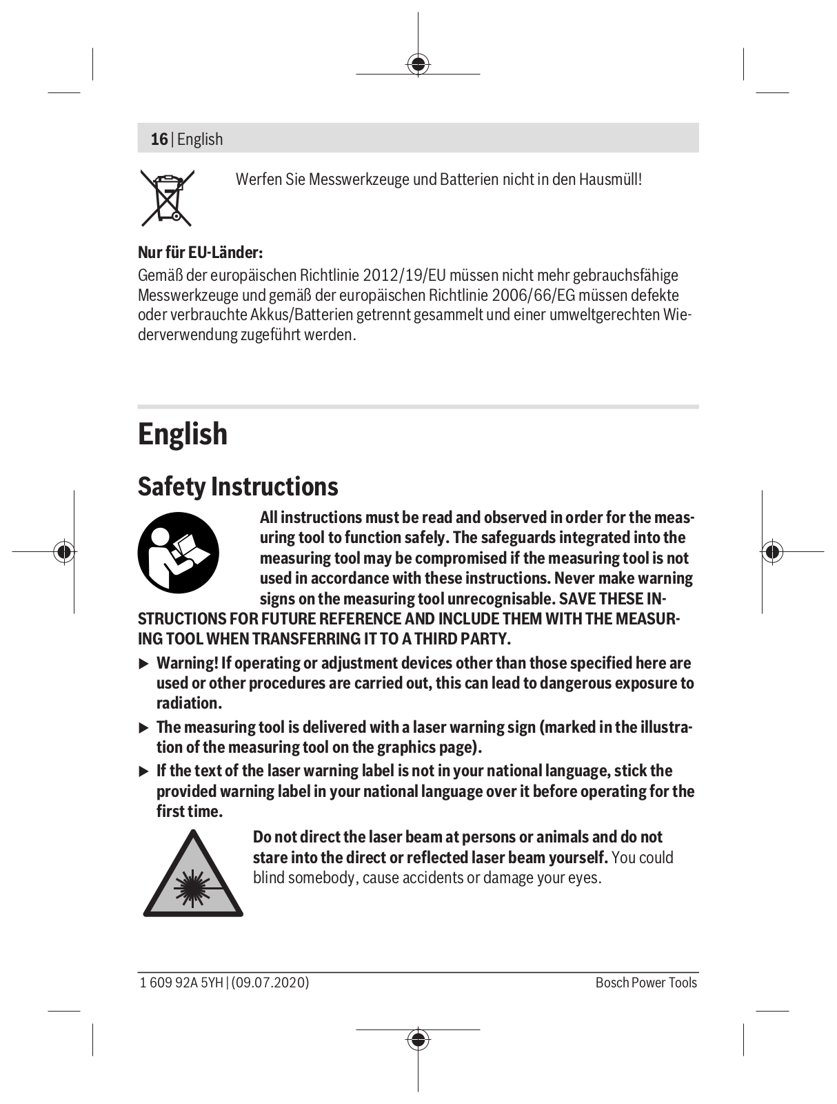
Do not direct the laser beam at persons or animals and do not

stare into the direct or reflected laser beam yourself. You could

blind somebody, cause accidents or damage your eyes.

1 609 92A 5YH | (09.07.2020)


Bosch Power Tools


English | 17

uIf laser radiation hits your eye, you must close your eyes and immediately turn your head away from the beam.

uDo not make any modifications to the laser equipment.

uDo not use the laser goggles as protective goggles. The laser goggles make the laser beam easier to see; they do not protect you against laser radiation.

uDo not use the laser goggles as sunglasses or while driving. The laser goggles do not provide full UV protection and impair your ability to see colours.

uHave the measuring tool serviced only by a qualified specialist using only original replacement parts. This will ensure that the safety of the measuring tool is maintained.

uDo not let children use the laser measuring tool unsupervised. They could accidentally dazzle someone.

uDo not use the measuring tool in explosive atmospheres which contain flammable liquids, gases or dust. Sparks may be produced inside the measuring tool, which can ignite dust or fumes.

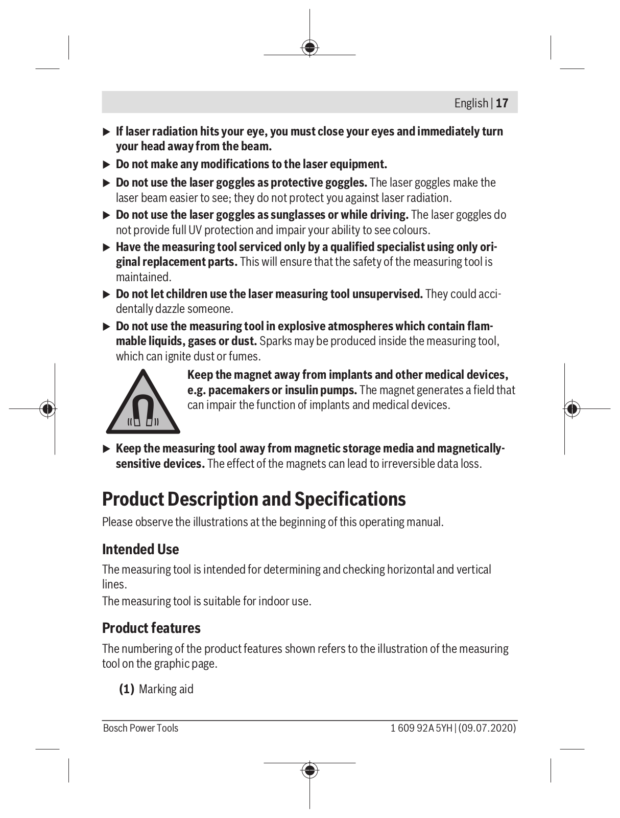
Keep the magnet away from implants and other medical devices,

e.g. pacemakers or insulin pumps. The magnet generates a field that

can impair the function of implants and medical devices.

uKeep the measuring tool away from magnetic storage media and magneticallysensitive devices. The effect of the magnets can lead to irreversible data loss.

Product Description and Specifications

Please observe the illustrations at the beginning of this operating manual.

Intended Use

The measuring tool is intended for determining and checking horizontal and vertical lines.

The measuring tool is suitable for indoor use.

Product features

The numbering of the product features shown refers to the illustration of the measuring tool on the graphic page.

(1) Marking aid

Bosch Power Tools


1 609 92A 5YH | (09.07.2020)


18 | English

(2)On/off button

(3)Light-up ring

(4)Laser beam outlet aperture

(5)Battery compartment cover

(6)Battery compartment cover locking mechanism

(7)Pin pad

(8)Pin

(9)Serial number

(10)Magnet

(11)Tape measure housing

(12)Tape measure

(13)Holder for gel pad

(14)Gel pad

(15)Protective cap for gel pad

(16)Laser warning label

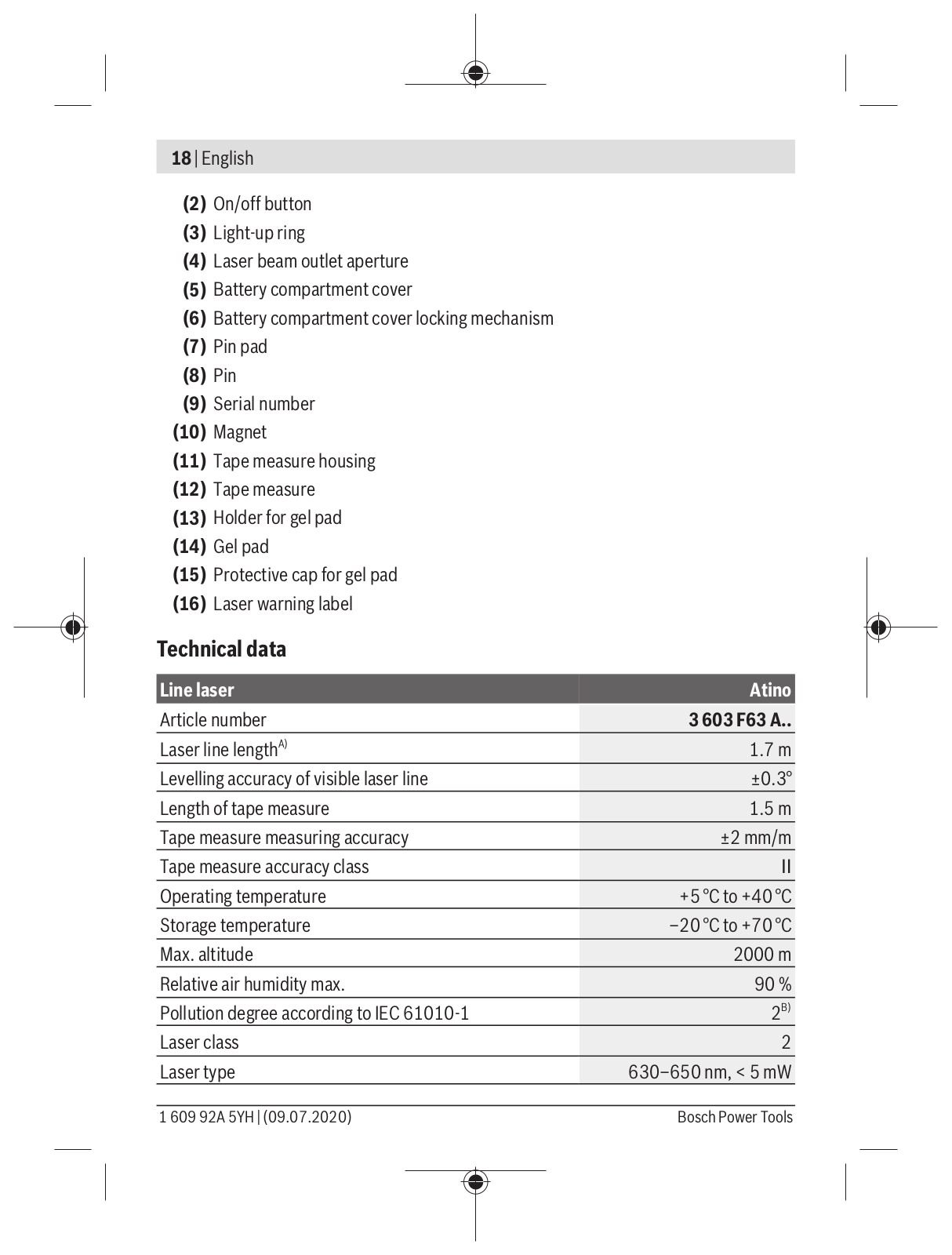
Technical data

Line laser

Atino

Article number

3 603 F63 A..

Laser line lengthA)

1.7 m

Levelling accuracy of visible laser line

±0.3°

Length of tape measure

1.5 m

Tape measure measuring accuracy

±2 mm/m

Tape measure accuracy class


Operating temperature

+5 °C to +40 °C

Storage temperature

–20 °C to +70 °C

Max. altitude

2000 m

Relative air humidity max.

90 %

Pollution degree according to IEC 61010-1

2B)

Laser class

2

Laser type

630–650 nm, < 5 mW

1 609 92A 5YH | (09.07.2020)


Bosch Power Tools


English | 19


Line laser

Atino

C6

5

Divergence

15 × 15 mrad (full angle)

Battery

1 × 1.5 V LR6 (AA)

Operating time at least

5 h

Weight according to EPTA-Procedure 01:2014

0.26 kg

Dimensions (length × width × height)

124 × 115 × 62 mm

A)depending on surface characteristics and ambient conditions

B)Only non-conductive deposits occur, whereby occasional temporary conductivity caused by condensation is expected.

The serial number (9) on the type plate is used to clearly identify your measuring tool.

Assembly

Inserting/Changing the Battery

It is recommended that you use alkaline manganese batteries to operate the measuring tool.

u Do not use lithium-ion batteries. This may result in damage to the measuring tool. To open the battery compartment cover (5), press on the locking mechanism (6) and remove the battery compartment cover. Insert the battery.

When inserting the batteries, ensure that the polarity is correct according to the illustration on the inside of the battery compartment.

Close the battery compartment before using the measuring tool.

If the battery is running low, the light-up ring (3) will flash yellow three times after the tool is switched on. The measuring tool can be operated for approx. another 15 min.

uTake the battery out of the measuring tool if you do not intend to use the tool for a long time. When it is stored in the measuring tool for longer periods, the battery can corrode and discharge itself.

Attaching the Measuring Tool

Selecting/changing the pad

The measuring tool can be attached to walls or other vertical surfaces. Depending on the type of substrate, either the gel pad (14) including the gel pad holder (13) or the pin pad (7) with 2 pins (8) can be used.

Bosch Power Tools


1 609 92A 5YH | (09.07.2020)


20 | English

As a general rule: The gel pad (14) is suitable for smooth surfaces. The pin pad (7) is suitable for coarse or rough surfaces and wallpaper on drywalls. The pin pad cannot be attached to concrete (regardless of the surface).

Substrate for attaching with the

Gel pad

Pin pad

(Ceramic) tiles

Wallpaper (woodchip, paper and fleece)

Smooth wooden surfaces

Plastered surfaces (up to a roughness of


around 2 mm)

Natural stone, marble, concrete


Gloss-coated surfaces (depending on the age and condition of the substrate)

To change the gel pad, turn the gel pad holder (13) anticlockwise and take the gel

pad (14) and holder off the measuring tool. Attach the pin pad (7) and turn it clockwise as far as it will go. The same procedure should also be followed when switching from the pin pad to the gel pad.

Attaching with the gel pad

Requirements:

The substrate must be dry and firm.

The gel pad is not guaranteed to stick to damp, particularly dusty, sharp-edged or highly textured surfaces. If attached to unsuitable surfaces such as these, the measuring tool can fall off and become damaged or damage the substrate.

If the gel pad becomes dirty or does not stick to smooth surfaces any more, it must be cleaned or replaced (see "Cleaning the Gel Pad", page 24).

Before every use, select an inconspicuous area lower down on the desired surface to check whether the gel pad will stick to this substrate, and that it can be safely removed without damaging the substrate.

Always remove the measuring tool once you have finished taking a measurement, or if the substrate is being worked on in some manner (e.g. drilling, screwdriving, or hammering).

Positioning the measuring tool on the substrate:

Turn the protective cap (15) of the gel pad anticlockwise and remove it. Remove the protective film from the gel pad before using it for the first time.

Gently press the measuring tool against the chosen surface until it is firmly affixed. Applying excessive pressure may damage the measuring tool.

1 609 92A 5YH | (09.07.2020)


Bosch Power Tools


English | 21

If the laser line is intended to appear at a certain height on the wall, this height should be marked in advance. Then position the measuring tool on the wall so that the height marking is situated in the centre of the marking aid (1) of the measuring tool.

Removing the measuring tool from the substrate (see figure A):

Carefully remove the measuring tool from the substrate as shown in the image. Removing the measuring tool from a delicate surface too quickly can damage the substrate.

After removing the tool, check that the gel pad (14) is still clean. If it has become dirty, it should be cleaned as necessary.

Place the protective cap (15) on the gel pad (14) and turn it clockwise to lock it in place. The measuring tool should only ever be transported and stored with the protective cap attached. If the gel pad becomes dirty, it will lose its adhesive strength.

Attaching with the pin pad (see figure B)

The substrate must be dry and firm.

To ensure the attachment is secure, position the measuring tool with the pin pad (7) on the substrate so that the pins are diagonally aligned to the measuring tool. It is not recommended to attach with pins horizontally or vertically to the measuring tool.

Insert the pins into the recesses on the pin pad. Ensure that the pins are securely affixed to the substrate.

If the laser line is intended to appear at a certain height on the wall, this height should be marked in advance. Then position the measuring tool on the wall so that the height marking is situated in the centre of the marking aid (1) of the measuring tool.

Always remove the measuring tool once you have finished taking a measurement, or if the substrate is being worked on in some manner (e.g. drilling, screwdriving, or hammering).

Operation

Starting Operation

uProtect the measuring tool from moisture and direct sunlight.

uDo not expose the measuring tool to any extreme temperatures or variations in temperature. For example, do not leave it in a car for extended periods of time. In case of large variations in temperature, allow the measuring tool to adjust to the ambient temperature before putting it into operation. The precision of the measuring tool may be compromised if exposed to extreme temperatures or variations in temperature.

Bosch Power Tools


1 609 92A 5YH | (09.07.2020)


22 | English

uAvoid substantial knocks to the measuring tool and avoid dropping it. Damaging the measuring tool can cause accuracy to be compromised. Calibrate the measuring tool after it has been dropped or subjected to heavy impact. Check the laser line by comparing it with a known horizontal or vertical reference line.

Switching On/Off

To switch on the measuring tool, briefly press the On/off button (2). The light-up

ring (3) flashes green three times when the battery has sufficient capacity; if the battery is weak, it flashes yellow three times.

If the measuring tool is roughly vertical, it sends a laser line out of the outlet aperture (4) immediately after switching on.

uDo not direct the laser beam at persons or animals and do not stare into the laser beam yourself (even from a distance).

To switch off the measuring tool, briefly press the on/off button (2) again.

uNever leave the measuring tool unattended when switched on, and ensure the measuring tool is switched off after use. Others may be blinded by the laser beam.

If no button on the measuring tool is pressed for approx. 15 minutes and the housing is not rotated, the measuring tool will automatically switch off to preserve battery life.

Levelling in the laser line (see figure C)

The laser line is only switched on if the measuring tool is tilted no more than 10° forwards or backwards.

The laser line can either be levelled in horizontally to the right (90°) or left (270°), or vertically upwards (0°) or downwards (180°).

The levelling status is indicated by means of the light-up ring (3):

Light-up ring

Levelling

Red

The laser line is neither horizontal nor vertical. Turn the housing of


the measuring tool so that it is horizontal or vertical as required.

Yellow

The laser line is close to being completely horizontal or vertical. To

(only one corres-

precisely adjust the laser line, turn the housing in the direction of

ponding half of the

the lit half of the light-up ring.

light-up ring is dis-


played)


Green

The laser line has been successfully levelled in either horizontally or


vertically.

After successfully levelling in the laser line, make sure to let go of the housing carefully without rotating it again.

1 609 92A 5YH | (09.07.2020)


Bosch Power Tools


English | 23

Working Advice

Working with the tape measure (see figure D)

The zero point of the tape measure (12) is situated in the centre of the marking aid (1) and can be marked directly on the substrate.

Note: The zero point marking can be offset by up to ±1 mm compared to the laser line. Pull the tape measure housing (11) away from the measuring tool and mark additional points at the required distances at the height of the laser line. When marking, ensure that the light-up ring (3) continues to be illuminated green and that the measuring tool is consequently levelled in.

Do not pull the tape measure (12) out any further than up to the end of the imprinted scale.

The tape measure will roll itself up again automatically. Hold the tape measure hous-

ing (11) with a relaxed grip and allow the tape measure to slowly retract itself. Make sure that the tape measure housing engages in the recess on the measuring tool.

Note: Do not let go of the tape measure while it is unrolled. Uncontrolled retraction may damage the tape measure.

Calibrating the Laser Line

Calibration should be carried out in the following cases:

After the tool has been dropped or subjected to heavy impact

Every 6 months

If necessary, check the levelling of the laser line on a known horizontal or vertical reference line.

Always perform a thorough and complete calibration to avoid incorrect measuring results.

Attach the measuring tool to a vertical surface.

While the measuring tool is either switched on or off, press and hold the on/off button (2) until the laser beam starts flashing and the light-up ring (3) is no longer lit.

Slowly and evenly rotate the housing of the measuring tool once by more than 360° (either clockwise or anticlockwise). The rotation should take at least 15 s.

The calibration process is completed successfully once the light-up ring (3) lights up green.

If the light-up ring (3) lights up red after calibration, the calibration has failed. Restart the calibration.

Bosch Power Tools


1 609 92A 5YH | (09.07.2020)


24 | English

Rectifying Errors


Problem

Corrective measures

The light-up ring (3) flashes yellow 3 times

Replace the battery.

during operation, then the measuring tool


switches off.


The measuring tool is not within the operat-

Allow the measuring tool to reach the cor-

ing temperature range specified in the

rect temperature and switch it back on

technical data and switches itself off.

once it is back within the operating temper-


ature range.

The gel pad (14) does not affix properly.

– Check whether the substrate is suitable


for the gel pad.


– If the gel pad is dirty, it should be


cleaned.


– If the gel pad is damaged, it should be


replaced.

The laser line is not vertical or horizontal as

Calibrate the laser line.

required after it has been levelled in.


Maintenance and Service

Maintenance and Cleaning

Keep the measuring tool clean at all times.

Never immerse the measuring tool in water or other liquids.

Wipe off any dirt using a damp, soft cloth. Do not use any detergents or solvents.

The areas around the outlet aperture of the laser in particular should be cleaned on a regular basis. Make sure to check for lint when doing this.

Cleaning the Gel Pad

Clean the gel pad (14) whenever it has become contaminated with dust or other particles, or if its adhesive strength has been reduced.

uOnly wash the gel pad when it has been detached from the tool. The measuring tool itself must not be washed or submerged in water.

To detach the gel pad, turn the gel pad holder (13) anticlockwise and take off the holder.

Rinse the gel pad (14) with water. Wash it as necessary using a common household neutral soap or a detergent. Do not use any cleaning agents that contain alcohol or solvents. If necessary, the protective cap (15) should also be cleaned.

1 609 92A 5YH | (09.07.2020)


Bosch Power Tools


English | 25

Leave the gel pad, holder and protective cap to dry completely. The gel pad must not be warmed up (e.g. through warm air or heating).

Place the protective cap (15) on the gel pad (14) and turn it clockwise to lock it in place. Place the gel pad holder (13) on the measuring tool and turn it clockwise to secure it.

If the adhesive strength is still not sufficient even after the gel pad (14) has been cleaned, it should be replaced.

After-Sales Service and Application Service

Our after-sales service responds to your questions concerning maintenance and repair of your product as well as spare parts. You can find explosion drawings and information on spare parts at: www.bosch-pt.com

The Bosch product use advice team will be happy to help you with any questions about our products and their accessories.

In all correspondence and spare parts orders, please always include the 10 digit article number given on the nameplate of the product.

Great Britain

Robert Bosch Ltd. (B.S.C.)

P.O. Box 98

Broadwater Park

North Orbital Road

Denham Uxbridge

UB 9 5HJ

At www.bosch-pt.co.uk you can order spare parts or arrange the collection of a product in need of servicing or repair.

Tel. Service: (0344) 7360109

E-Mail: boschservicecentre@bosch.com

You can find further service addresses at:

www.bosch-pt.com/serviceaddresses

Disposal

Measuring tools, accessories and packaging should be recycled in an environmentally friendly manner.

Do not dispose of measuring tools or batteries with household waste.

Bosch Power Tools


1 609 92A 5YH | (09.07.2020)


26 | Français

Only for EU countries:

According to the Directive 2012/19/EU, measuring tools that are no longer usable, and according to the Directive 2006/66/EC, defective or used battery packs/batteries, must be collected separately and disposed of in an environmentally correct manner.

Français

Consignes de sécurité

Pour une utilisation sans danger et en toute sécurité de l’appareil de mesure, lisez attentivement toutes les instructions et tenez-

en compte. En cas de non-respect des présentes instructions, les fonctions de protection de l’appareil de mesure risquent d’être altérées. Faites en sorte que les étiquettes d’avertissement se

trouvant sur l’appareil de mesure restent toujours lisibles. CONSERVEZ CES INSTRUCTIONS DANS UN LIEU SÛR ET REMETTEZ-LES À TOUT NOUVEL UTILISATEUR DE L’APPAREIL DE MESURE.

uAttention – L’utilisation d’autres dispositifs de commande ou d’ajustage que ceux indiqués ici ou l’exécution d’autres procédures risque de provoquer une exposition dangereuse aux rayonnements.

uL’appareil de mesure est fourni avec une étiquette d’avertissement laser (repérée dans la représentation de l’appareil de mesure sur la page des graphiques).

uSi le texte de l’étiquette d’avertissement laser n’est pas dans votre langue, recouvrez l’étiquette par l’autocollant dans votre langue qui est fourni, avant de procéder à la première mise en service.

Ne dirigez jamais le faisceau laser vers des personnes ou des animaux et ne regardez jamais dans le faisceau laser projeté par l’appareil ou réfléchi. Vous risqueriez d’éblouir des personnes, de provo-

quer des accidents ou de causer des lésions oculaires.

uAu cas où le faisceau laser frappe un œil, fermez immédiatement les yeux et déplacez la tête pour l’éloigner du faisceau. N’apportez jamais de modifications au dispositif laser.

uN’apportez aucune modification au dispositif laser.

1 609 92A 5YH | (09.07.2020)


Bosch Power Tools


Français | 27

uN’utilisez pas les lunettes de vision laser comme des lunettes de protection. Les lunettes de vision laser aident seulement à mieux voir le faisceau laser ; elles ne protègent pas contre les effets des rayonnements laser.

uN’utilisez pas les lunettes de vision laser comme des lunettes de soleil ou pour la circulation routière. Les lunettes de vision laser n’offrent pas de protection UV complète et elles faussent la perception des couleurs.

uNe confiez la réparation de l’appareil de mesure qu’à un réparateur qualifié utilisant uniquement des pièces de rechange d’origine. La sécurité de l’appareil de mesure sera ainsi préservée.

uNe laissez pas les enfants utiliser l’appareil de mesure laser sans surveillance. Ils pourraient éblouir des personnes par inadvertance.

uNe faites pas fonctionner l’appareil de mesure en atmosphère explosive, en présence de liquides, gaz ou poussières inflammables. L’appareil de mesure peut produire des étincelles susceptibles d’enflammer les poussières ou les vapeurs.

N’approchez pas l’aimant de personnes porteuses d’implants chi-

rurgicaux ou d’autres dispositifs médicaux (stimulateurs car-

diaques, pompe à insuline, etc.). L’aimant génère un champ magné-

tique susceptible d’altérer le fonctionnement des implants chirurgi-

caux et dispositifs médicaux.

uN’approchez pas l’appareil de mesure de supports de données magnétiques ou d’appareils sensibles aux champs magnétiques. Les aimants peuvent provoquer des pertes de données irréversibles.

Description des prestations et du produit

Référez-vous aux illustrations qui se trouvent au début de la notice d’utilisation.

Utilisation conforme

L’appareil de mesure est conçu pour projeter et vérifier des lignes horizontales et verticales.

L’appareil de mesure est approprié pour une utilisation en intérieur.

Éléments constitutifs

La numérotation des éléments de l’appareil se réfère à la représentation de l’appareil de mesure sur la page graphique.

(1) Aide au marquage

Bosch Power Tools


1 609 92A 5YH | (09.07.2020)


28 | Français

(2)Touche Marche/Arrêt

(3)Anneau lumineux

(4)Orifice de sortie du faisceau laser

(5)Couvercle du compartiment pile

(6)Verrouillage du couvercle du compartiment pile

(7)Support à épingles

(8)Épingle

(9)Numéro de série

(10)Aimant

(11)Boîtier de mètre ruban

(12)Mètre ruban

(13)Support de gel pad

(14)Gel pad

(15)Bouchon protecteur de gel pad

(16)Étiquette d’avertissement laser

Caractéristiques techniques

Mètre laser lignes

Atino

Référence

3 603 F63 A..

Longueur de la ligne laserA)

1,7 m

Précision de nivellement de la ligne laser visible

±0,3°

Longueur du mètre ruban

1,5 m

Précision de mesure du mètre ruban

±2 mm/m

Classe de précision du mètre ruban


Températures de fonctionnement

+5 °C … +40 °C

Températures de stockage

–20 °C … +70 °C

Altitude d’utilisation maxi

2 000 m

Humidité d’air relative maxi

90 %

Degré d’encrassement selon CEI 61010-1

2B)

Classe laser

2

Type de laser

630−650 nm, < 5 mW

1 609 92A 5YH | (09.07.2020)


Bosch Power Tools


Français | 29


Mètre laser lignes

Atino

C6

5

Divergence

15 × 15 mrad (angle plein)

Pile

1 × 1,5 V LR6 (AA)

Autonomie minimale

5 h

Poids suivant EPTA-Procedure 01:2014

0,26 kg

Dimensions (longueur x largeur x hauteur)

124 × 115 × 62 mm

A)dépend de la nature de la surface et des conditions ambiantes

B)N’est conçu que pour les salissures/saletés non conductrices mais supporte occasionnellement la conductivité due aux phénomènes de condensation.

Pour une identification précise de votre appareil de réception, servez-vous du numéro de série (9) inscrit sur la plaque signalétique.

Montage

Mise en place/changement de la pile

Il est recommandé d’utiliser des piles alcalines au manganèse.

u N’utilisez pas de batteries lithium-ion. Cela pourrait endommager le télémètre. Pour ouvrir le couvercle du compartiment pile (5), appuyez sur le verrouillage (6) et retirez le couvercle du compartiment pile. Introduisez la pile.

Respectez ce faisant la polarité indiquée sur le graphique qui se trouve à l’intérieur du compartiment à piles.

Refermez le compartiment pile avant d’utiliser l’appareil de mesure.

Quand la pile devient faible, l’anneau lumineux (3) clignote trois fois en jaune à la mise en marche. L’appareil de mesure peut alors encore être utilisé pendant env. 15 min.

uSortez la pile de l’appareil de mesure si vous savez que l’appareil ne va pas être utilisé pendant une longue durée. Elle risque sinon de se corroder et de se décharger.

Fixation de l’appareil de mesure

Sélection/remplacement du support de fixation

L’appareil de mesure peut être fixé sur des murs ou d’autres surfaces verticales. Selon la nature de la surface, il convient d’utiliser soit le gel pad (14) et son support (13), soit le support (7) avec les 2 épingles (8).

Bosch Power Tools


1 609 92A 5YH | (09.07.2020)


30 | Français

Règle générale : Le gel pad (14) est conçu pour les surfaces lisses. Le support à épingles (7) est conçu pour les surfaces rugueuses et les papiers peints sur des cloisons sèches. Le support à épingles ne peut pas être fixé sur du béton (quel que soit l’aspect de la surface).

Surfaces appropriées à l’utilisation du

Gel pad

Support à épingles

Carrelages (céramique)

Papiers peints (ingrain, papier ou non-tissé)

Surfaces en bois lisses

Crépis (avec jusqu’à 2 mm de profondeur de


rugosité)

Pierre naturelle, marbre, béton


Surfaces peintes bien lisses (selon l’âge et l’état du revêtement)

Pour changer de support de fixation, tournez le support de gel pad (13) dans le sens antihoraire et retirez-le avec le gel pad (14). Positionnez le support à épingles (7) et tour- nez-le dans le sens horaire jusqu’en butée. Pour remplacer le support à épingles par le gel pad, procédez de façon analogue.

Fixation avec le gel pad

Conditions préalables :

La surface sur laquelle doit être fixé le gel pad doit être sèche et propre.

Le gel pad n’adhère pas bien sur les surfaces poussiéreuses, avec des arêtes vives ou du relief. Sur de telles surfaces, l’appareil de mesure risque de tomber et d’être endommagé ou bien d’endommager la surface.

Si le gel pad est sale ou n’adhère plus bien sur des surfaces même lisses, nettoyez-le ou remplacez-le (voir « Nettoyage du gel pad », Page 35).

Avant chaque utilisation, testez à un endroit peu visible et assez près du sol si le gel pad adhère correctement et s’il peut être retiré sans endommager la surface.

Retirez toujours l’appareil de mesure après avoir effectué la mesure ou avant de procéder à des travaux (perçages, perforations, vissages, etc.).

Positionnement de l’appareil de mesure sur la surface :

Tournez le bouchon protecteur (15) du gel pad dans le sens antihoraire et retirez-le. Avant la première utilisation, retirez le film protecteur du gel pad.

Appliquez en exerçant une légère pression l’appareil de mesure contre la surface jusqu’à ce qu’il tienne bien. Une pression trop importante risque de détériorer l’appareil de mesure.

Si la ligne laser doit parcourir le mur à une certaine hauteur, marquez préalablement cette hauteur. Appliquez ensuite l’appareil de mesure contre le mur de façon à ce que le

1 609 92A 5YH | (09.07.2020)


Bosch Power Tools


Loading...
+ 309 hidden pages