

Bosch ASL-APE3P-BASE, ASL-APE3P-BEXT, ASL-APE3P-CLI, ASL-APE3P-RDR, ASL-APE3P-VIDB Operation Manual
...Page 1

Access Professional Edition
3.0
en Configuration Manual
Page 2

Page 3

Access Professional
Edition 3.0
Table of contents
Table of Contents | en 3
1
1.1 Restrictions and options 6
1.2 Installation on one computer 8
1.3 Installation on multiple computers 9
1.4 System Prerequisites 10
2
2.1 Introduction 12
2.2 User Login 15
2.3 Menu and Tool bar 18
2.4 General system settings 22
2.5 Layout of the main dialog 27
2.6 Menu and tool bar 28
2.7 Layout of the main dialog 32
2.8 Menu and Tool bars 33
2.9 Enrollment Configuration 35
2.9.1 Enrollment via AMC connected readers 37
3
3.1 Creating new configurations 42
3.2 Opening configurations 44
3.3 Activating a new configuration 45
3.4 Propagating configurations to the controllers 46
4
4.1 Defining and modifying new controllers 49
4.2 Controller Settings 54
5
5.1 Input signals 57
5.2 Output signals 60
5.3 Defining conditions for output signals 67
5.4 Creating Extension boards 73
6
6.1 Creating and modifying door models 76
6.2 Display and parameterization 82
6.3 Door models with special settings 91
Bosch Access Systems GmbH 2014-03 | 3.0 | Configuration Manual
System Overview 5
General 12
Configurations 42
Controllers 49
Signals 57
Entrances 76
Page 4

4 en | Table of Contents
Access Professional
Edition 3.0
7
8
9
Areas 92
Personnel Groups 97
Access Authorizations 101
9.1 Create and assign 101
9.2 Special rights 105
10
Special days 110
10.1 Create and modify 110
11
Daymodels 113
11.1 Create and modify 113
12
Timemodels 115
12.1 Create and modify 118
13
Texts 120
13.1 Displaytexts 121
13.2 Event Log messages 122
14
15
Additional Personnel data 125
Map Viewer and Alarm Management 129
15.1 Configuring a map 130
15.2 Adding a device to a map 133
16
17
Card Definition 136
Appendix 140
17.1 Signals 140
17.2 Default Doormodels 142
17.3 Doormodel 01 143
17.4 Doormodel 03 145
17.5 Doormodel 06c 146
17.6 Doormodel 07 146
17.7 Doormodel 10 149
17.8 Doormodel 14 151
17.9 Examples of mantrap configurations 153
17.10 Configuring Entrance Model 07 156
17.11 Display Arming/Disarming 158
17.12 Procedures in Access Control 160
17.13 Access PE ports 164
18
PIN types 166
2014-03 | 3.0 | Configuration Manual Bosch Access Systems GmbH
Page 5

Access Professional
Edition 3.0
System Overview | en 5
1
System Overview
Access Professional Edition System (hereunder referred to as
Access PE) consists of four modules
– LAC Service: a process which is in constant communication
with the LACs (Local Access Controllers – hereafter
referred to as Controllers). AMCs (Access Modular
Controllers) are used as Controllers.
– Configurator
– Personnel Management
– Logviewer
These four can be divided into server and client modules.
The LAC service needs to remain in constant contact with the
controllers because firstly it constantly receives messages from
them regarding movements, presence and absence of
cardholders, secondly because it transmits data modifications,
e.g. assignment of new cards, to the controllers, but mainly
because it carries out meta-level checks (access sequence
checks, anti-passback checks, random screening).
The Configurator should also run on the server; however it can
be installed on client workstations and operated from there.
The modules Personnel Management and Logviewer belong to
the Client component and can be run on the Server in addition,
or on a different PC with a network connection to the server.
The following Controllers can be used.
– AMC2 4W (with four Wiegand reader interfaces) - can be
extended with an AMC2 4W-EXT
– AMC2 4R4 (with four RS485 reader interfaces)
Bosch Access Systems GmbH 2014-03 | 3.0 | Configuration Manual
Page 6

6 en | System Overview
Access Professional
Edition 3.0
1.1
Restrictions and options
You can use Access PE for systems that do not exceed the
following thresholds for connectable components and
manageable data volume.
– Max. 10,000 cards
– Up to three cards per person
– PIN length: 4 to 8 characters (configurable)
– PIN types:
– Verification PIN
– Identification PIN
– Arming PIN
– Door PIN
– Access variants:
– Only with card
– Only with PIN
– PIN or card
– Max. 255 time models
– Max. 255 access authorizations
– Max. 255 area-time authorizations
– Max. 255 authorization groups
– Max. 16 workstations
– Max. 128 readers
– Max. one I/O extension board (AMC2 8I-8O-EXT, AMC2
16I-16O-EXT or AMC2 16I-EXT) per Controller
– The following restrictions apply to each controller type:
2014-03 | 3.0 | Configuration Manual Bosch Access Systems GmbH
Page 7

Access Professional
Edition 3.0
System Overview | en 7
Controller AMC2 4W AMC2 4W
Readers/entrances
Max. readers per
4 8 8
with AMC2
4W-EXT
AMC2 4R4
AMC
Max. readers per
1 1 8
interface/bus
Table 1.1: System limits — readers and entrances
Video system — restrictions and options
– Max. 128 cameras
– Up to 5 cameras per entrance
– 1 identification camera
– 2 back surveillance cameras
– 2 front surveillance cameras
– You can configure one of these cameras as an alarm
and log book camera.
Offline Locking System (OLS) — restrictions and options
– Max. 1024 doors
– The number of entrances and authorization groups in the
authorizations depends on the dataset length that can be
written to the cards.
– Max. 15 time models
– Up to 4 periods per time model
– Max. 10 special days/holidays (from the online system)
Bosch Access Systems GmbH 2014-03 | 3.0 | Configuration Manual
Page 8

8 en | System Overview
Access Professional
Edition 3.0
1.2
Installation on one computer
The following figure shows a complete Access PE system
installed on a single computer. Controllers can be connected via
a serial interface. If a dialog reader is used then this is also
connected via a serial interface.
Figure 1.1: System Overview – Single Computer Configuration
2014-03 | 3.0 | Configuration Manual Bosch Access Systems GmbH
Page 9

Access Professional
Edition 3.0
System Overview | en 9
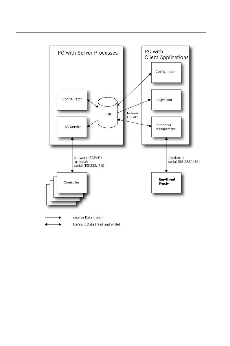
1.3
Installation on multiple computers
The following figure shows an Access PE system distributed
across 2 computers. This is particularly beneficial in cases
where the Server to which the Controllers are connected is in a
locked computer room, but the personnel data is maintained,
for example, by the personnel department elsewhere.
The Access PE Client can be installed on up to 16 computers,
which access common data on the Server via the network.
Client workstations can be configured to use two monitors.
Window positions maintained by the operating system, ensure a
familiar operators’ environment across login sessions.
Bosch Access Systems GmbH 2014-03 | 3.0 | Configuration Manual
Page 10
10 en | System Overview
Access Professional
Edition 3.0
Figure 1.2: System overview – Distributed System
1.4
2014-03 | 3.0 | Configuration Manual Bosch Access Systems GmbH
System Prerequisites
The installation of Access PE requires:
Operating Systems (one of):
– Windows XP SP2 Professional
– Windows XP SP3 Professional
– Windows 2008 Server
– Windows 7
Other software:
Page 11

Access Professional
Edition 3.0
– To run the AmcIpConfig application supplied (and the
– To create and display lists and reports, you must install
Separate setups are available on the installation CD.
Hardware Requirements
Both Server an Client require a Standard Windows PC with:
– 4 GHz CPU
– 4 GB RAM at least
– 20 GB free disk space (Server)
– 1 GB free disk space (Client)
– 100 Mbit Ethernet Network Card (PCI)
– Graphical adapter with 1024x768 resolution and 32k colors
– Resolution support:
– CD/DVD-ROM Drive
– I/O Expansion Option
– USB Keyboard and Mouse
System Overview | en 11
Bosch Video SDK), you need the .NET Framework 4.0
platform.
Crystal Reports applications.
– 1024 by 768
– 1280 by 1024
– 2048 by 768
– 2560 by 1024
Notice!
Microsoft Windows XP Professional is required for any video
integration.
Please consult the documentation of the chosen devices and
ensure that you can use an operating system supported by both
software and devices.
Bosch Access Systems GmbH 2014-03 | 3.0 | Configuration Manual
Page 12

12 en | General
Access Professional
Edition 3.0
2
2.1
General
Introduction
Access PE is an Access Control System which has been
designed to offer the highest standards of security and flexibility
to small and medium sized installations.
Access PE owes its stability and upgradeability to a 3-tier
design: The top tier is the administration level with its
controlling services. All administrative tasks are carried out
here, e.g. the registration of new cards and the assignment of
access rights.
The second tier is formed by the Local Access Controllers
(LACs) which govern each group of doors or entrances. Even
when the system is offline a LAC is able independently to make
access control decisions. LACs are responsible for controlling
the entrances, governing door opening times or requesting PINcodes at critical access points.
The third tier consists of card readers which, like the
Controllers, are identical across all BOSCH access controls.
They provide not only a consistently high degree of security, but
also a simple upgrade and expansion path for the system,
protecting previous investments.
Access PE multi-user version allows multiple workstations to
control the system. Customizable user rights levels regulate
access and guarantee security. In this way it is possible, for
example, to maintain card data from one workstation whilst
using another to verify whether an employee is present in the
building.
Access PE offers exceptionally flexible configuration of access
rights, time models and entrance parameters. The following list
gives an overview of the most important features:
Quick & Easy card Assignment
2014-03 | 3.0 | Configuration Manual Bosch Access Systems GmbH
Page 13

Access Professional
Edition 3.0
Cards (up to three) can be assigned to persons either manually
or using a dialog reader connected to a PC via a serial
connection. Only one card can be active per person at any one
time. When upgrading cards the old card is automatically
overwritten and becomes invalid, thus preventing old cards from
gaining access even if those responsible forgot or were unable
to cancel them.
Access Rights (including Group Privileges)
Each person can inherit group privileges as well as having
individual rights assigned to him. Privileges can be restricted by
area and time to an accuracy of one minute. Group privileges
can be used to grant and limit access rights for any or all
cardholders simultaneously. Group privileges can be made
dependent on time models which restrict their access to certain
times of day.
Access tracking
By defining Areas it is possible to track and enforce a correct
sequence of accesses. Even without monitoring, this
configuration makes it possible to display a cardholder's
location.
Anti-Passback
When a card has been read it can be blocked for a defined
period from entering at the same access point. Hence it is
possible to prevent "passback", where a user hands his card
back across a barrier to provide access for an unauthorized
person.
Automatic Cancelation of cards upon Expiration
Visitors and temporary staff frequently require access for a
limited period only.
cards can be registered for a specific time period, so that they
automatically lose their validity when that period expires.
Time Models and Day Models
General | en 13
Bosch Access Systems GmbH 2014-03 | 3.0 | Configuration Manual
Page 14

14
en | General
Access Professional
A cardholder can be assigned to specific time models which
regulate the hours in which that person has access. Time
models can be defined flexibly using day models which
determine how specific weekdays, weekends, holidays and
special days deviate from normal working days.
Identification via PIN-Code
Instead of a card a person can use a special PIN-Code to enter.
Verification via PIN-Code
Particularly sensitive areas can be programmed to require
additional PIN-Codes. This protection can in turn be made
dependent on time models, so that, for instance, a PIN-Code is
only required for access during holiday times or outside of
defined working hours.
Flexible Door Management
Flexible parameterization of individual door models allows an
optimum balance between security and comfort. The "shunt" or
alarm suppression period can be individually specified to
regulate for how long a door may remain open. In cooperation
with an alarm system the access point can then optionally be
locked.
Periodic Door Release
In order to facilitate access, door alarms can be shunted to
release doors for specific periods. Door release periods can be
defined manually or automatically via a time model.
Time and Attendance
Access points can be parameterized to record ingress and
egress for time & attendance purposes.
Card Design
The graphical add-in module Card Personalization (CP) is fully
integrated into the Access Control system to allow the operator
to create cards without switching applications.
Assignment of Photos
If the add-in module Card Personalization (CP) is not activated
photographic identification can nevertheless be imported and
associated with cardholders.
Edition 3.0
2014-03 | 3.0 | Configuration Manual Bosch Access Systems GmbH
Page 15

Access Professional
Edition 3.0
Offline locking system
Areas which are not covered, for whatever reason, by the highavailability online access control system can nevertheless be
locked offline.
Administration of video devices
Entrances can be equipped additionally with cameras to identify
and track the movements of persons using them.
General | en 15
2.2
User Login
– Start the user applications using the desctop icons:
Personnel Management
Configurator
Logviewer
Map and Alarm Management
Video Verification
or choose the tools via : Start > Programs > Access
Professional Edition
– Start the : Map & Alarm Management application using the
desctop icon
Professional Edition > Map & Alarm Management.
– Start the : Video Verification application using the desctop
or via : Start > Programs > Access Professional
icon
Edition > Video Verification.
– Start the : Configurator application using the desctop icon
or via : Start > Programs > Access Professional Edition >
Configurator.
or via : Start > Programs > Access
Bosch Access Systems GmbH 2014-03 | 3.0 | Configuration Manual
Page 16
16
en | General
Access Professional
– Start the : Logviewer application using the desctop icon
or via : Start > Programs > Access Professional Edition >
Logviewer.
– Start the : Personnel Management application using the
desctop icon
or via : Start > Programs > Access
Professional Edition > Personnel Management.
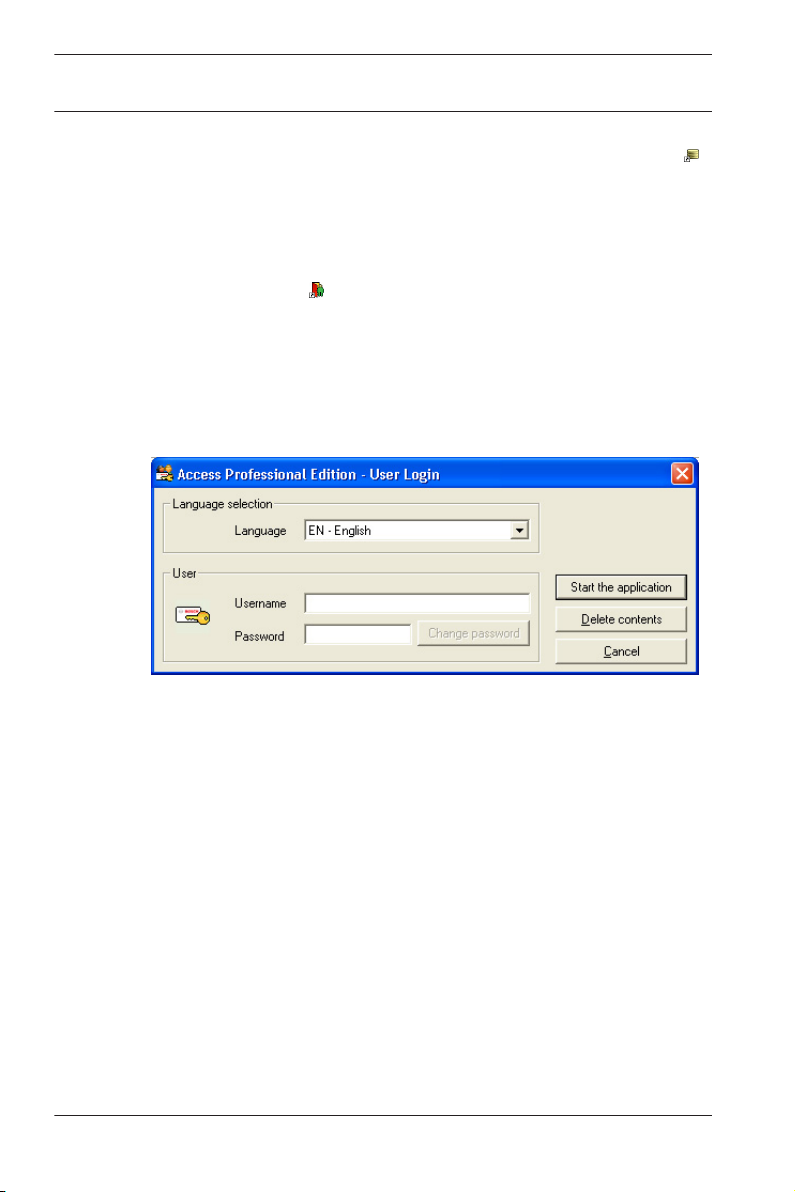
The system's applications are protected from unauthorized use.
A login with a valid username and password is required in order
to invoke the dialog-based subsystems.
Edition 3.0
The upper drop-down list can be used to select the desired
interaction language. The default is that language which was
used to install the application. If there is a change of user
without restarting the application then the previous language is
retained. For this reason it is possible for a dialog box to appear
in an undesired language. In order to avoid this, please log in to
Access PE again.
Access PE applications can be run in the following languages:
– English
– German
– Russian
– Polish
– Chinese (PRC)
– Dutch
– Spanish
2014-03 | 3.0 | Configuration Manual Bosch Access Systems GmbH
Page 17
Access Professional
Edition 3.0
– Portuguese (Brazil)
Notice!
All facilities such as device names, labels, models and user-
rights schemes are displayed in the language in which they
were entered.Similarly buttons and labels controlled by the
operating system may appear in the language of the operating
system.
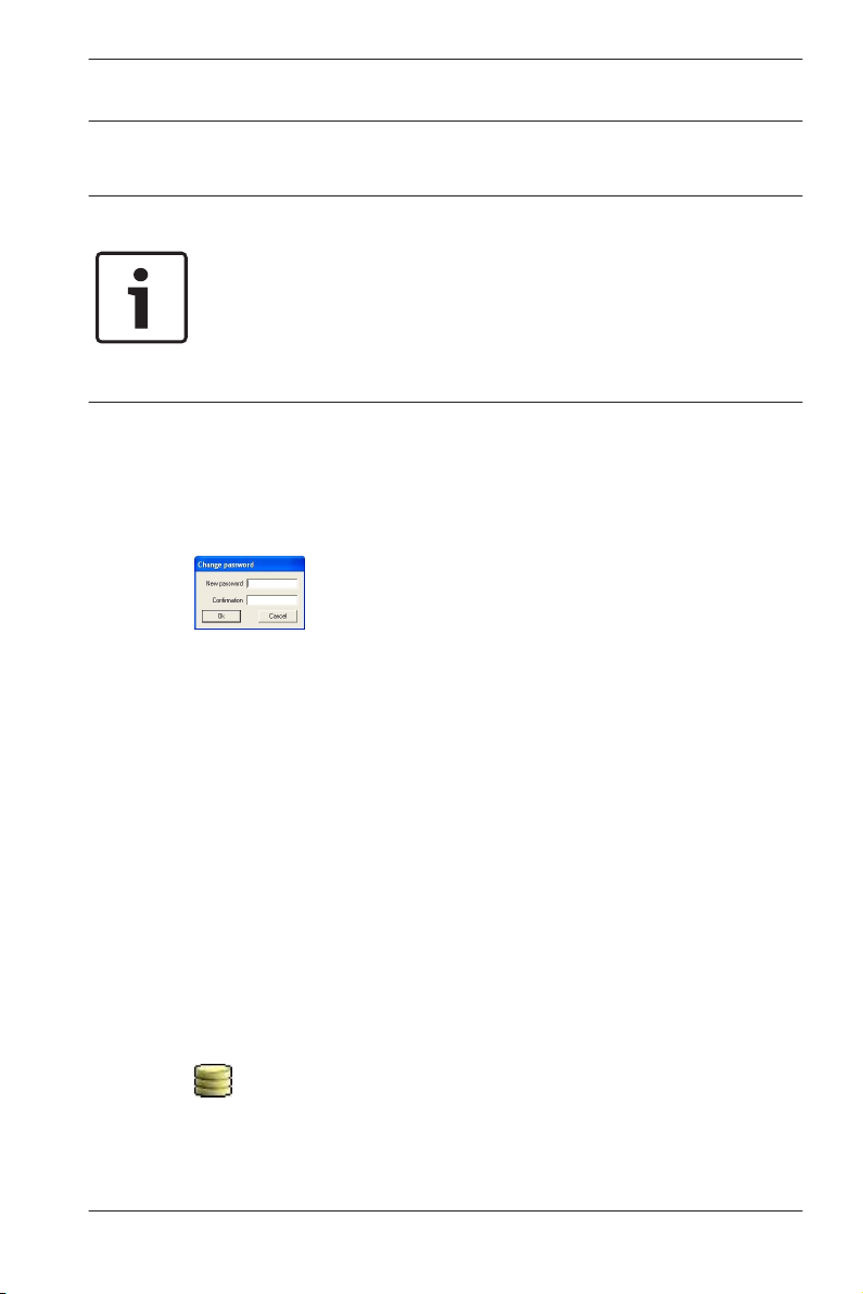
If a valid username/password pair are entered then the button :
Change Password appears. This can be used to start a new
dialog to change the password.
The button Start the application checks the user's privileges
and, based on these, starts the application. If the system is
unable to authenticate the login then the following error
message appears: : Wrong username or password!
General | en 17
Login via Personnel Management
If the user is already logged into the Access PE Personnel
Management application, and if the user's rights include the
other tools, he can start the : LogViewer, : Configurator, : Alarm
Management and : Video Verification using the toolbar buttons.
If the user is already logged into the Access PE Personnel
Management application, and if the user's rights include :
LogViewer, then : LogViewer may be invoked directly using the
button in the tools list, without requiring a separate login to
the LogViewer application.
Bosch Access Systems GmbH 2014-03 | 3.0 | Configuration Manual
Page 18
18 en | General
If the user is already logged into the Access PE Personnel
Management application, and if the user's rights include :
Configurator, then : Configurator may be invoked directly using
the button in the tools list, without requiring a separate
login to the Configurator application.
If the user is already logged into the Access PE Personnel
Management application, and if the user's rights include : Video
Verification, then : Video Verification may be invoked directly
using the
login to the Configurator application.
If the user is already logged into the Access PE Personnel
Management application, and if the user's rights include : Alarm
Management, then : Alarm Management may be invoked
Access Professional
Edition 3.0
button in the tools list, without requiring a separate
directly using the
separate login to the Configurator application.
2.3
2014-03 | 3.0 | Configuration Manual Bosch Access Systems GmbH
Menu and Tool bar
The following functions can be invoked via the menus, the icons
in the toolbar or specific keyed shortcuts.
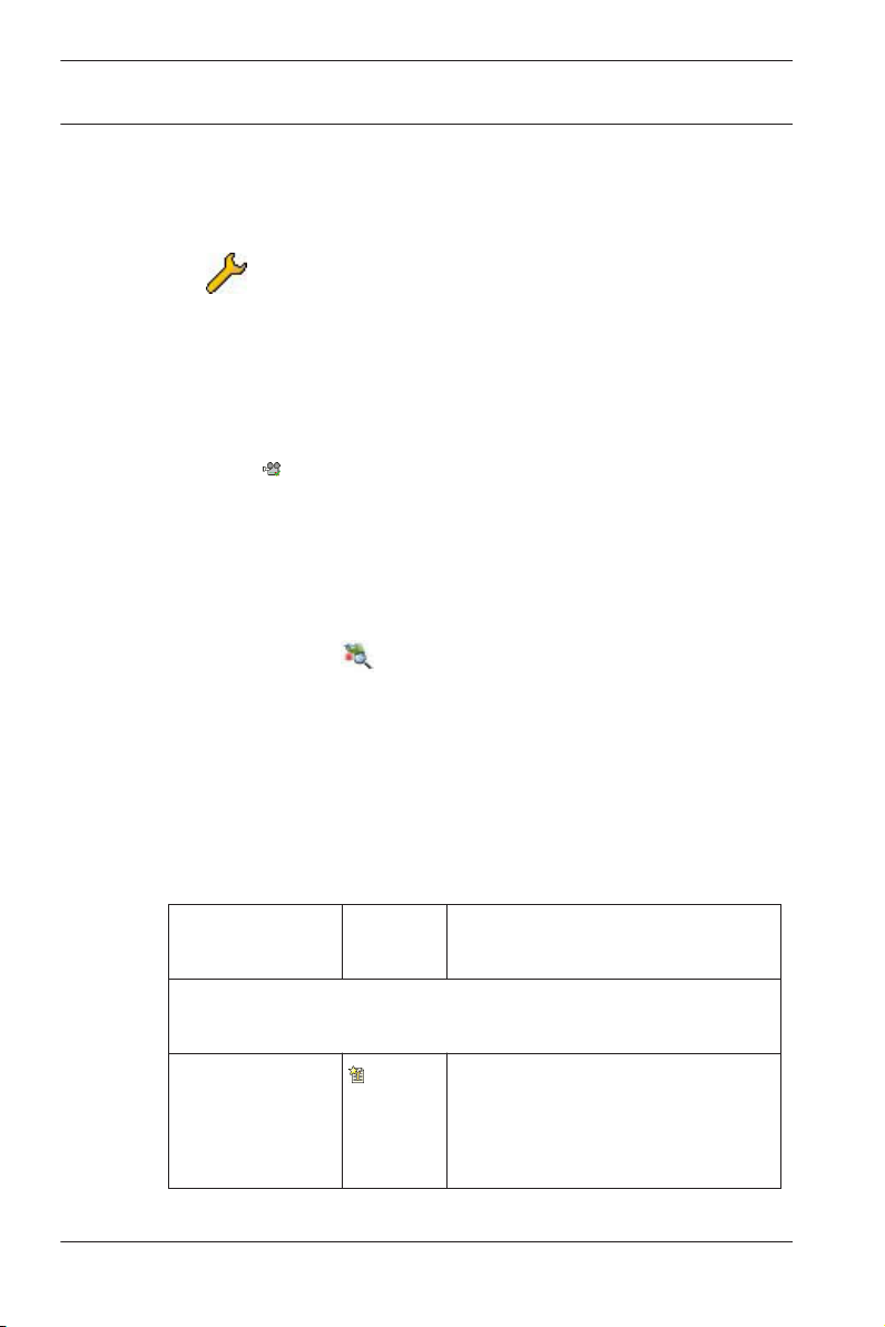
Function Icon/
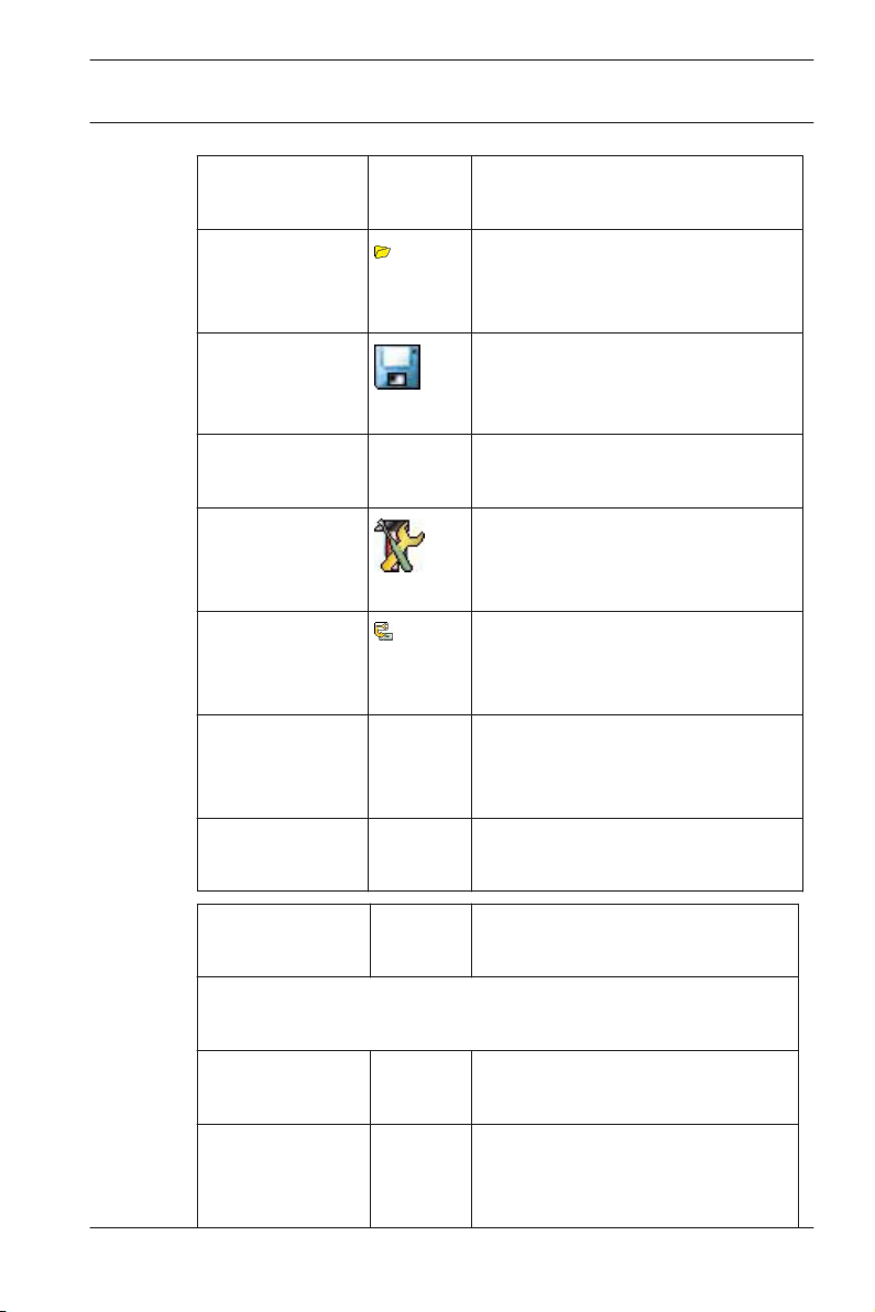
Menu File
New
button in the tools list, without requiring a
Description
Shortcut
Clears all configuration dialog
Crtl + N
boxes (except for default
settings) in order to define a
new configuration.
Page 19
Access Professional
Edition 3.0
General | en 19
Function Icon/
Description
Shortcut
Open...
Crtl + O
Opens a dialog box to select a
different configuration for
loading.
Save
Saves changes into the current
configuration file.
Crtl + S
Save as... Saves the current configuration
into a new file.
Activate
Configuration
Activates a loaded configuration
and saves the hitherto active
configuration.
Send
Configuration to
Propagates saved configuration
changes to the LAC-Service.
LAC
List recently
active
configurations
Opens configurations directly,
circumventing the Open
function's selection dialog.
Exit Shuts down Access PE
Configurator.
Function Icon/
Description
Shortcut
Menu View
Tool bar Toggles display of the tool bar
(default = on).
Status bar Toggles display of the status bar
at the bottom edge of the
window (default = on).
Bosch Access Systems GmbH 2014-03 | 3.0 | Configuration Manual
Page 20
20 en | General
Access Professional
Edition 3.0
Function Icon/
Description
Shortcut
Menu Configuration
General Opens the General Settings
dialog for setting up Controllers
and general system parameters.
Input signals Opens the dialog box for
parametrizing input signals.
Output signals Opens the dialog box for
parametrizing output signals.
Entrances Opens the Entrances dialog for
parametrizing doors and card
readers.
Areas Opens the Area Configuration
dialog for dividing the protected
installation into virtual areas.
Holidays Opens the Holidays dialog box
for defining holidays and special
days.
Day Models Opens the Day Models dialog
box for defining time periods
within a day for the activation of
access functions.
Time Models Opens the dialog Time Models
for defining timezones
dependent on days of the week
or calendar.
2014-03 | 3.0 | Configuration Manual Bosch Access Systems GmbH
Page 21
Access Professional
Edition 3.0
General | en 21
Function Icon/
Description
Shortcut
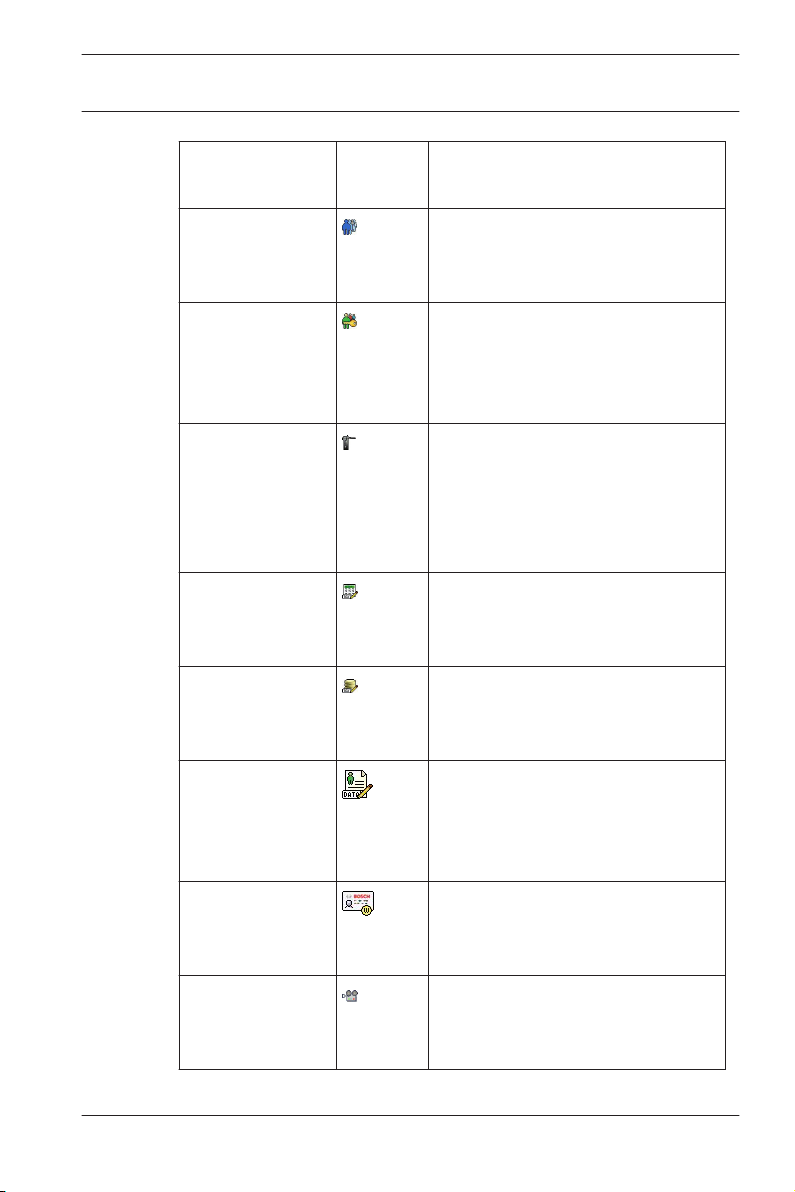
Personnel
Groups
Opens the dialog box Personnel
Groups for dividing personnel
into logical groups.
Access
Authorization
Groups
Opens the dialog box Access
Authorization Groups for
defining groupings of
authorizations to entrances.
Offline locking
system
Opens the Offline locking
system dialog for configuring
special elements of the
installation (Entrances, Time
models, Authorization groups).
Display Texts Opens the dialog box Display
texts for editing the texts to be
displayed at the card readers.
Log Messages Opens the dialog box Log
Messages for editing and
categorizing log messages.
Additional
personnel fields
Opens the dialog box
Additional personnel fields for
defining data fields for
personnel.
Wiegand - cards Opens the dialog box Wiegand-
cards for defining the structures
of card data.
Administering
video devices
Opens the Video devices dialog
for configuring cameras to be
used in video verification.
Bosch Access Systems GmbH 2014-03 | 3.0 | Configuration Manual
Page 22
22 en | General
Access Professional
Edition 3.0
2.4
Function Icon/
Shortcut
Map Viewer and
Alarm
management
Menu ? (Help)
Help topics Opens this help text.
About Access
Professional
Edition Configurator
Displays general information
Description
Opens the Map Viewer for an
areal view of maps and control
devices and the alarm list for
alarm handling.
about Access Professional
Edition - Configurator
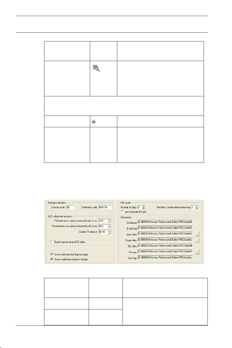
General system settings
General system settings are displayed below the list of
controller settings. These are valid for all installations.
Parameter
Country Code 00 Some card data are appended
Customer Code 056720
2014-03 | 3.0 | Configuration Manual Bosch Access Systems GmbH
Default
value
Description
to the manually entered card
number.
Page 23

Access Professional
Edition 3.0
General | en 23
Parameter Default
Description
value
Poll interval on
serial
connected LAC
in ms
Read-Timeout
on serial
connected LAC
in ms
200 The time interval in milliseconds
between pollings by the LACService to verify intact
connections to a controller.
500
Range of values for poll interval:
1 to 500
Possible values for readtimeout: 1 to 3000
Create TA dataat00:01 Specification of the time at
which the Time & Attendance
data file should be created.
Export
personnel and
TA data
deactivated When activated this option
causes time & attendance data
to written continuously to the
export file.
When not activated the data file
is created at the time specified
by the parameter Create TA
data at.
The file containing attendance time-stamps is created in the
following directory:
C:\Program Files\Bosch\Access Professional Edition\PE\Data
\Export
Under the name TA_<Current date YYYYMMDD>.dat
Bosch Access Systems GmbH 2014-03 | 3.0 | Configuration Manual
Page 24

24 en | General
Access Professional
Edition 3.0
Parameter Default
value
Show welcome/
activated Given appropriate reader type
leaving
message
Show
aktiviert Readers with display will show
cardholder
name in display
Number of
4 Determines the number of
digits
Description
and settings (Arriving, Leaving
or Check ok in the Entrances
dialog) the reader will display
those welcome and leaving
texts which are stored for the
cardholder in the Personnel
Data dialog of the Personnel
Management application.
Does not apply to Wiegand
readers.
the Display Name as stored in
the cardholder's Personnel
Data.
Does not apply to Wiegand
readers.
digits a verification or arming
PIN requires.
This setting applies also to the
door PIN which can be set
during the configuration of
entrances.
Possible values: 4 to 8
2014-03 | 3.0 | Configuration Manual Bosch Access Systems GmbH
Page 25

Access Professional
Edition 3.0
General | en 25
Parameter Default
value
use separate
If no separate IDS PIN is set,
IDS PIN
Description
then a verification PIN can be
used to arm the IDS.
Only if the check box is
selected do the input fields for
the arming-PIN become active
in the Personnel dialog screen.
In this case the verification PIN
can no longer be used to arm
the IDS.
Bosch Access Systems GmbH 2014-03 | 3.0 | Configuration Manual
Page 26
26 en | General
Access Professional
Edition 3.0
Parameter Default
value
Count of retries
3 Number of failed attempts to
before blocking
Directory paths
to:
Database
Log file
Import files
Export files
DLL files
Image data
Test-Logging
C:\Program
Files
\BOSCH
\Access
Professiona
l Edition\PE
\Data...
\Db
\MsgLog
\Import
\Export
\Dll
\Pictures
\Log
Description
enter the PIN. If the cardholder
mistypes the PIN this many
times then s/he will incur a
system-wide block which can
only be removed by an
authorized system user
(Personnel Management).
Possible values: 1 to 9
These are the default paths. The
directories for import, export
and image files can be changed.
Notice!
When using Wiegand controllers and readers, in order to use
Identification-, arming- or door-PINs the Wiegand card definition
PIN or Card (Nr. 6) needs to be activated.
2014-03 | 3.0 | Configuration Manual Bosch Access Systems GmbH
Page 27
Access Professional
Edition 3.0
General | en 27
2.5
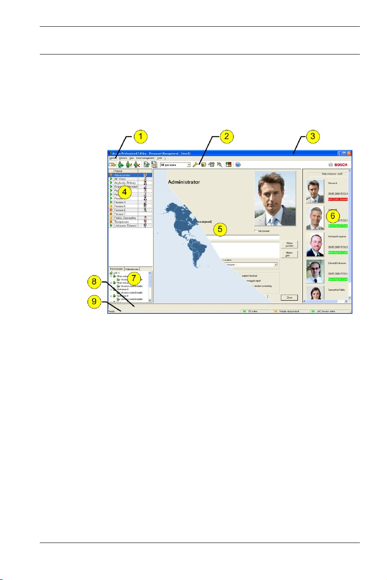
Layout of the main dialog
The dialog consists of the following parts:
1 = Menu bar — contains dialog functions displayed
according to the menu order.
2 = Toolbar — contains shortcut keys for the most
important dialog functions.
3 = Title bar — conforms to Windows standard and
contains buttons for minimizing or closing the dialog
window. The name of the registered user appears in
square brackets.
4 = Personnel table — lists all people known in the system
along with their attendance status (authorization and
location).
Bosch Access Systems GmbH 2014-03 | 3.0 | Configuration Manual
Page 28

28 en | General
5 = Dialog field — the first time this field is opened or
6 = Online swipe — lists the last five people (with
7 = Device status — lists the configured devices and
8 = Event display — faults are indicated by a flashing red
9 = Status bar — displays information on buttons and
When you enable the Video Verification component, additional
facilities will be added to this dialog; see Personnel
Management.
When you enable the Video Verification component, additional
facilities will be added to this dialog.
Access Professional
Edition 3.0
when no user is logged in, it shows a neutral image
(map of the world). When an entry is selected from the
Personnel list, this person's data is displayed.
database image) that have swiped their cards at the
entrance selected.
entrances along with their connection status. Enables
door control functions.
bar (flashes three times) with details on the cause.
menu entries that are controlled with the cursor.
Status display on card personalization program (CP),
dialog readers and LAC service.
2.6
2014-03 | 3.0 | Configuration Manual Bosch Access Systems GmbH
Menu and tool bar
The following functions are available via the menus or the icon
buttons.
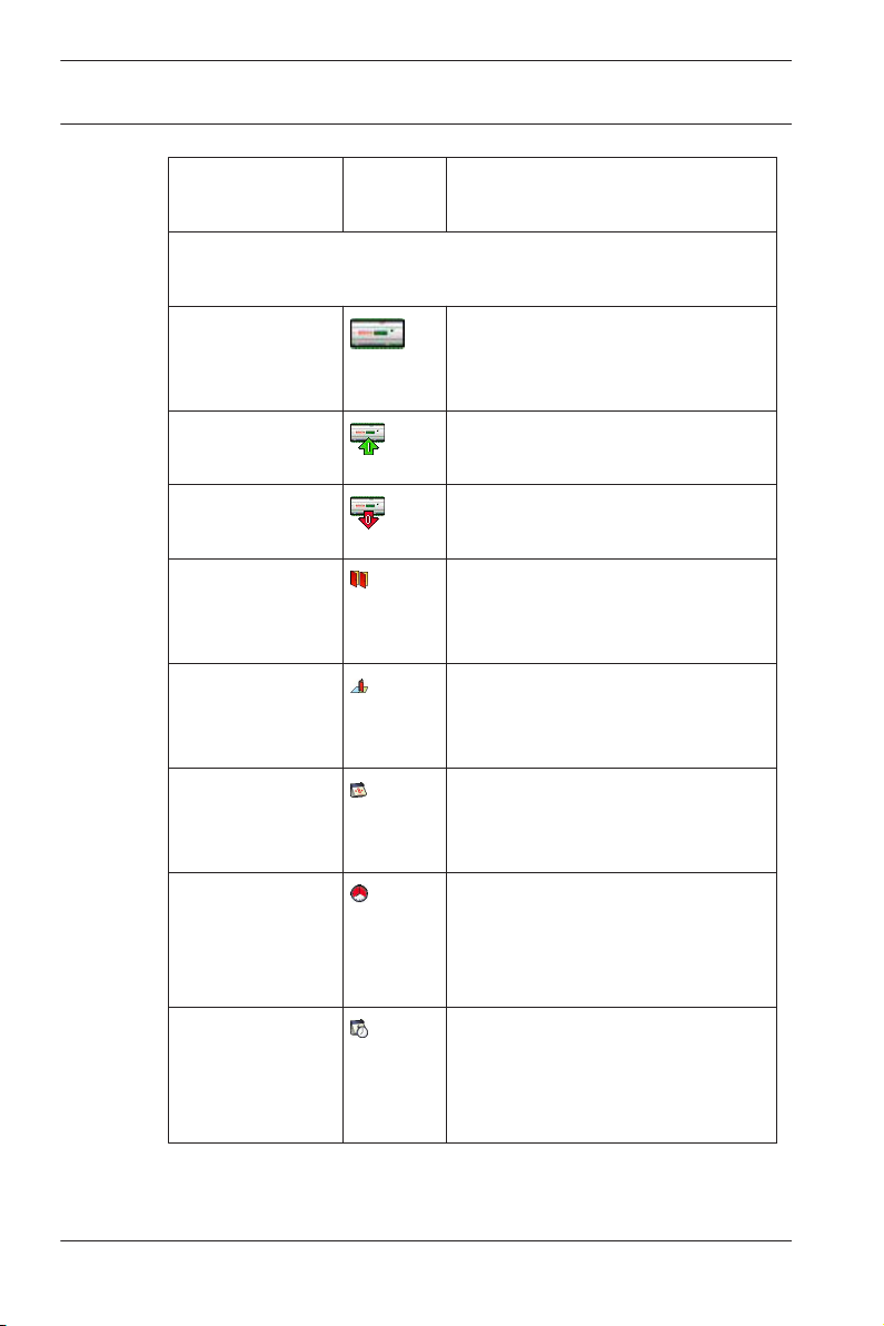
Function Icon Description
Menu Options
Refresh Refreshes the Personnel list
Page 29
Access Professional
Edition 3.0
Function Icon Description
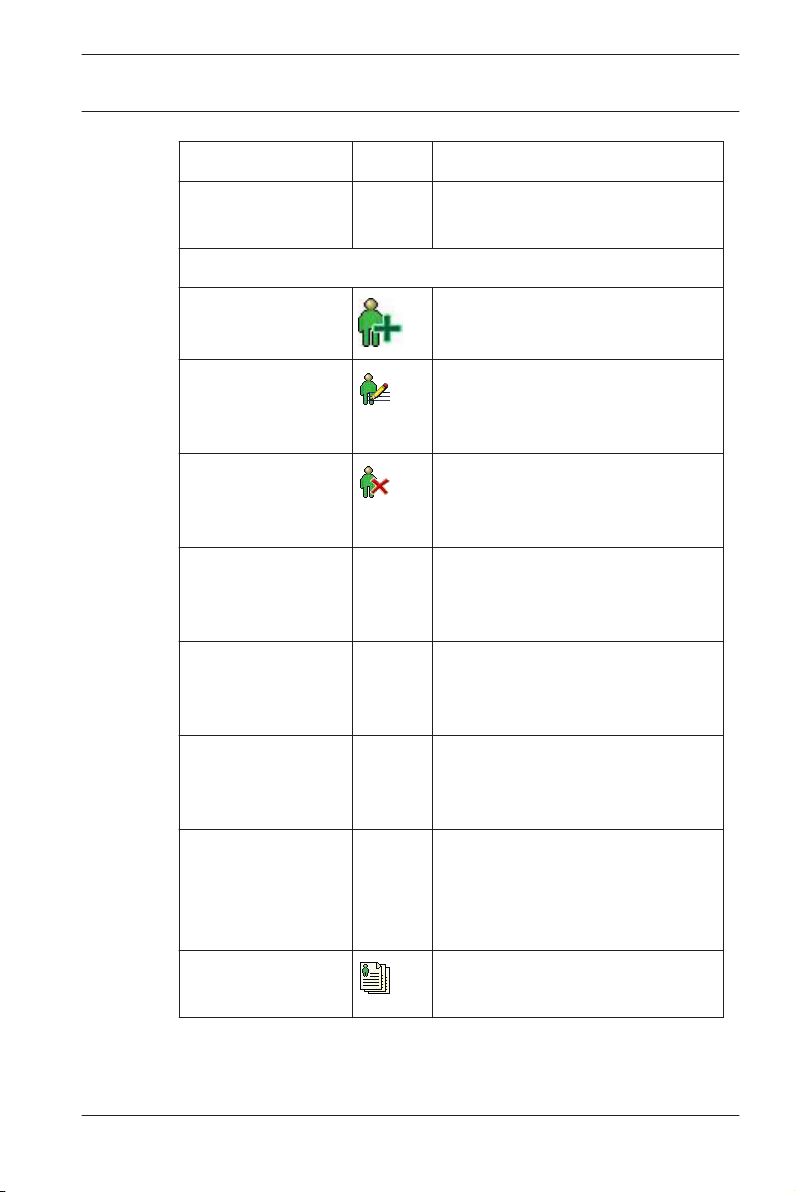
Exit Exits the Access PE Personnel
Menu Persons
New person Opens a blank personnel and
Modify person Opens the personnel and card
Delete person Deletes the selected person
General | en 29
Management application
card data dialog
data dialog with the data of the
selected person.
(after confirming a safety check
dialog).
Transmit selected
person to the LAC
service
Transmit all
persons to the
LAC service
Set all persons
absent
Transmits the selected person's
data to the LAC service and
reports success.
Transmits all persons' data to
the LAC service and reports
success.
Sets all persons absent (after
confirming a safety check
dialog).
Set location of all
persons present
to unknown
Sets the location of all persons
to unknown and deactivates
access tracing for the next
booking of each person.
View/print reports Calls the dialog for creating
report lists.
Bosch Access Systems GmbH 2014-03 | 3.0 | Configuration Manual
Page 30
30 en | General
Function Icon Description
Access Professional
Edition 3.0
List
control
Restricts the persons shown to
those of the selected group.
Menu View
Symbol bar Toggles display of the tool bar.
Default = on.
Status bar Toggles display of the status
bar. Default = on.
Personnel data:
State
Card No.
Personnel-No.
Company
Personnel Group
Choice of columns displayed in
the personnel overview in
addition to symbol and name
columns.
Default = State - Company -
Location
Phone
Location
Menu Door management
open door These
functio
ns are
The entrance selected in the
device list is displayed and can
be opened (one-off).
also
availabl
e via
2014-03 | 3.0 | Configuration Manual Bosch Access Systems GmbH
Page 31

Access Professional
Edition 3.0
Function Icon Description
Long-term open
lock door The entrance selected in the
Menu Tools
User logon Log in/off Personnel
the
context
menu
(right
click on
the
desired
door/
entranc
e)
General | en 31
The entrance selected in the
device list is displayed and can
be opened (long-term).
device list is displayed and can
be locked.
management.
Execute the
Configurator
Executes Configurator and
transfers data from personnel
management.
Execute log
viewer
Executes Log viewer and
transfers data from personnel
management.
Execute Video
verification
Execute Alarm and
Map management
Starts the application for
executing video verification.
Starts the Map viewer and
Alarm management processing
application.
Video panel Shows four displays in the
dialog field for individual video
camera feeds.
Properties Opens a dialog box for general
system settings.
Menu ? (Help)
Bosch Access Systems GmbH 2014-03 | 3.0 | Configuration Manual
Page 32

32 en | General
Function Icon Description
Help topics Opens this help file.
Access Professional
Edition 3.0
2.7
About Access
Professional
Edition Personnel
Management
Displays information about
Personnel Management.
Layout of the main dialog
1 = Menu bar - Contains all dialog functions arranged in
menus.
2 = Tool bar - Contains the most important dialog
functions as icon buttons
3 = Title bar - Conforms to Windows standard and
contains buttons to minimize and close the main
dialog window. The name of the current user is
displayed in square brackets.
2014-03 | 3.0 | Configuration Manual Bosch Access Systems GmbH
Page 33

Access Professional
Edition 3.0
4 = Device status - List of the configured devices and
5 = Message list - List of messages arrived hitherto. The
6 = Filter selection - Predefined and customized filters
7 = Alarm activation - Triggers the activation/
8 = Status bar - Dates of the log files opened. Status of
General | en 33
entrances along with their connection status.
display can be modified by specific filter settings.
can be selected from the combo-box.
deactivation of alarms for messages. An incoming
message can be accompanied by an acoustic signal.
the LAC Service. Alarm settings.
2.8
Menu and Tool bars
The following functions are available for log evaluation via
menus and icon buttons.
Menu Function Icon
button
File Print... Print the log messages
Exit Closes the LogViewer
Filter Filter
definition
Description
displayed
application.
Opens the message
filtering dialog.
Bosch Access Systems GmbH 2014-03 | 3.0 | Configuration Manual
Page 34

34 en | General
Access Professional
Edition 3.0
Menu Function Icon
button
Continuous
mode on
Continuous
mode off
Events
previous
day
Description
Starts continuous
message display. This
icon is only active
when the function is
not already running
and the message filter
is set to the current
day.
Continuous message
display is the default
setting.
Pauses the continuous
message display. This
icon is only active
when continuous
message display is
running.
Switch to previous
day's messages.
Events next
day
Switch to next day's
messages.
View Symbol bar Hides/Displays the
tool bar.
Default = on.
Status bar Hides/Displays the
status bar.
Default = on.
without a menuitem
2014-03 | 3.0 | Configuration Manual Bosch Access Systems GmbH
Page 35

Access Professional
Edition 3.0
General | en 35
2.9
Menu Function Icon
button
? (Help) Help topics Opens this help file.
About
LogViewer
Opens Help About
Description
Access PE LogViewer.
Enrollment Configuration
Enrollment Readers (RS 232) > Tools > Settings calls a dialog
in which it is possible to perform basic configuration tasks
(activate, modify) from any workstation.
– Administrative workplaces, where persons are assigned
cards, can be fitted with an enrollment reader. This must be
parameterized and configured according to the
manufacturer's specifications, or those delivered with the
device. If an enrollment reader is set up then manual card
checking is deactivated.
The required settings for supported readers are:
Reader name
DELTA 1200 Prox RS232 9600 8 N 1
DELTA 1200 iClass RS232 57600 8 E 1
DELTA 1200 USB Hitag, Legic, Mifare 9600 8 N 1
DELTA 1200 RS232 Hitag, Legic, Mifare 19200 8 N 1
Rosslare ARD-1200EM USB 9600 8 N 1
LECTUS secure 5000 MD 9600 8 N 1
Bosch Access Systems GmbH 2014-03 | 3.0 | Configuration Manual
BAUD D P S
Page 36

36
en | General
D = Data bits N = none
P = Parity E = even
S = Stop bits O = odd
Access Professional
Edition 3.0
– If the system has been installed with the optional Card
Personalization (CP) module then the corresponding check
box is selected in settings. Unchecking this box blocks all
functions for card design/creation.
2014-03 | 3.0 | Configuration Manual Bosch Access Systems GmbH
Page 37

Access Professional
Edition 3.0
– In addition the automatic transfer of personnel data via
– The display of card information during card assignment can
General | en 37
Connection to the LAC Server is also checked. This box
should always remain checked.
be disabled here. This display is only necessary when,
contrary to default settings (see General Settings in Access
PE Configurator) card data are required which do not
conform to the company standard settings.
2.9.1
Enrollment via AMC connected readers
Make sure that at least one reader is configured with a Door
Model 06c, which is the door model for enrollment.
Start the Configuration Browser and select a Local Access
Controller (LAC) (e.g. AMC2…)
Bosch Access Systems GmbH 2014-03 | 3.0 | Configuration Manual
Page 38

38 en | General
Click the Entrances symbol an add a new Entrance reader:
Access Professional
Edition 3.0
The dialog window Define Entrance opens:
2014-03 | 3.0 | Configuration Manual Bosch Access Systems GmbH
Page 39

Access Professional
Edition 3.0
General | en 39
In this dialog:
– Enter a Description (e.g. Enrollment Reader AMC)
– Select a LAC and a group ID (GID)
– Select a reader type (e.g. Wiegand)
– Select a number between 1 and 8 as Access Reader
Address
Click OK to conform the enrollment configuration.
Bosch Access Systems GmbH 2014-03 | 3.0 | Configuration Manual
Page 40

40
en | General
To assign the configured enrollment reader to a specific
workstation, you have to change tot he APE client.
– Select Tool > Properties.
Access Professional
Edition 3.0
Select an available enrollment reader to activate the enrollment
process.
Confirm that your enrollment reader is online.
If you don’t get an immediate response, restart the Personnel
Management dialog.
2014-03 | 3.0 | Configuration Manual Bosch Access Systems GmbH
Page 41

Access Professional
Edition 3.0
General | en 41
Bosch Access Systems GmbH 2014-03 | 3.0 | Configuration Manual
Page 42

42 en | Configurations
Access Professional
Edition 3.0
3
3.1
Configurations
The composition of a system (what entrances there are where,
how many readers and of what type, how access authorizations
are set up etc.) is saved in special files. Any number of these
configuration files can exist — however, only one can apply to
the current system. This makes it possible to test new
scenarios, carry out test runs and carry out quick system
changes.
Creating new configurations
All Access PE configurations are stored in the folder C:\BOSCH
\Access Professional Edition\PE\Data\Cfg (unless non-default
paths and folder names are chosen during installation). Two
configuration files are created by the installation, namely
Active.acf and Default.acf. Whereas Active.acf contains example
data, which may be helpful to the user, Default.acf contains only
predefined system data.
System data include:
– The area --outside--.
– Example holidays and special days
– The personnel groups Employees and Visitors
– Display texts for readers.
– Logbook texts
Upon startup Access PE always uses the configuration
Active.acf.
A configuration may find itself in different states, and it is
important to distinguish between them
– An Active configuration is one whose definitions, settings
etc. are currently being used by the running system.
– An Open (aka loaded) configuration is one which is
currently being edited by system users. It may later be
stored in a separate .acf file and/or later activated, but until
it is activated it has no influence on the running system.
2014-03 | 3.0 | Configuration Manual Bosch Access Systems GmbH
Page 43

!
Access Professional
Edition 3.0
Any number of configurations can be defined and stored in
Access PE. Because new configurations can be created and
modified independently of the running system, it is possible, for
example, to define new areas which will be included in the
monitored installation at a later date.
Using the
Default.acf, with its basic settings, can be opened (loaded). If
modified to create a new configuration it should be saved under
a different and appropriate name.
Configurations | en 43
button in the toolbar the default configuration
The
button starts a file-saving dialog in the Cfg directory.
The default filename untitled.acf should be replaced by a more
explanatory filename.
Warning!
The default configurations active.acf and default.acf should
never be renamed or overwritten. Always store modifications of
default.acf under a new name.
Bosch Access Systems GmbH 2014-03 | 3.0 | Configuration Manual
Page 44

44 en | Configurations
Access Professional
Edition 3.0
3.2
Opening configurations
Configurator is always started with the configuration Active.acf.
If a different configuration is to be used, then the button can
load an existing configuration from the folder C:\BOSCH\Access
Professional Edition\PE\Data\Cfg (by default).
If the user wishes to make changes to or expand an existing
configuration to be activated at a later date, then s/he can open
a basic configuration, modify it and then save it under a
different name. In this way it is possible to re-use and expand
upon previous configurations, and one does not have to start
every time from the very basic settings in default.acf.
Notice!
The active configuration too can be saved as a working copy
under a new name, and this loaded and worked on at a later
date.
2014-03 | 3.0 | Configuration Manual Bosch Access Systems GmbH
Page 45

!
Access Professional
Edition 3.0
Configurations | en 45
3.3
Activating a new configuration
Configurator offers the possibility of maintaining multiple
configurations in multiple .acf files. The active configuration is
always stored in the file Active.acf .
Caution!
As active.acf is overwritten when a new configuration is
activated, it is urgently recommended that the user make a
backup copy of the active configuration under a new filename.
Configuration files must be opened before they can be
activated. Therefore a previously modified and saved
configuration should be opened.
In order then to activate the opened configuration please
proceed as follows, either:
– Menu: File > Activate configuration or
– Use the
The activation then proceeds in stages:
– First confirm the safety check.
: Do you really want to replace the current configuration
with the new configuration?
– The hitherto active configuration is backed up as a file with
the name format: $yyyyMMddhhmmss -Active.acf (y =
year; M = month; d = day; h = hour; m = minute; s =
seconds).
– The currently open configuration is then stored under the
filename Active.acf i.e. the old active configuration will be
overwritten!
A information box shows the name of the saved file: : New
configuration was saved as <filename>!
button in the toolbar.
Bosch Access Systems GmbH 2014-03 | 3.0 | Configuration Manual
Page 46

46 en | Configurations
Access Professional
Edition 3.0
3.4
Propagating configurations to the controllers
After making changes in the active configuration Active.acf it is
necessary to propagate these changes down to the controllers.
This can be started in two ways:
– Menu File > Send configuration to LAC service
– Using the
The following dialog appears, in which you can choose which
configuration data will be propagated to the controllers.
Modified and saved data are preselected. You may select further
items or deselect already selected items.
When you have selected which data should be propagated to
the controllers then click OK.
button in the toolbar
Configuration data
General refresh ... log messages, additional fields or
System parameters ... LAC-Hardware has been modified.
Time models ... Holidays, Day or time models have
Reader texts ... Display texts have been modified.
2014-03 | 3.0 | Configuration Manual Bosch Access Systems GmbH
Propagation to the LACs becomes
necessary if...
card definitions have been modified.
been modified
Page 47

Access Professional
Edition 3.0
Configuration data Propagation to the LACs becomes
Door parameters ... at Entrances, one or more of the
Reader parameters ... at Entrances, one or more of the
Configurations | en 47
necessary if...
following have been modified
– the opening time (in 1/10 sec.)
– the door contact
– data relating to door control
(opening times, contacts, time
profiles etc.)
following have been modified
– data for the entry or departure
readers
– alarm suppression time (in 1/10
sec.).
– anti-passback behavior of the
entrance
– buttons to open the door
Door configuration ... at Entrances, the door model has
been modified.
Notice: Reinput and modification of the
address (serial number, reader-type)
can only be carried out in the input
mask Define Entrance.
Signal definitions ... parametrization of input or output
signals has been modified
Authorization
groups
... authorization groups without time
models have been modified, or a new
time model added or deleted.
Bosch Access Systems GmbH 2014-03 | 3.0 | Configuration Manual
Page 48

en | Configurations
48
Access Professional
Edition 3.0
Configuration data Propagation to the LACs becomes
necessary if...
Personnel data ... personnel data has been added or
modified, or access authorization
groups or time models have been
modified.
Complete
configuration
including LAC
service restart
.. the initial configuration of Access PE
has been concluded. A reset of the
controller can also cause the complete
configuration to be downloaded to the
controllers.
LAC service restart ... in general settings the polling interval
or the time for saving the TA data file
has been modified.
LAC service stop This option should only be used in
exceptional circumstances, e.g during
deinstallation in order to avoid a restart
of the computer.
Configurator sends a command to the : LAC Service to
propagate the configuration data to the controllers. The LAC
Service is responsible for the communication to and from the
controllers. This program is set up at installation time, as a
Windows Service which is automatically started upon booting.
Successful propagation to the LAC Service is reported as
follows:
2014-03 | 3.0 | Configuration Manual Bosch Access Systems GmbH
Page 49

Access Professional
Edition 3.0
Controllers | en 49
4
4.1
Controllers
The Local Access Controllers (LACs) are the points in Access PE
at which most access control decisions are made. Except for
system-wide control functions, such as the access sequence
check, the controllers can take independent decisions regarding
who is granted access. For this reason, they have all accessrelated data in their own memory so that limited and restricted
offline operation is also possible.
In Access PE it is predominantly AMC2 (Access Modular
Controller) controllers that are used. For replacements within
legacy systems, LACi (Local Access Controller integral)
controllers can also be configured.
Defining and modifying new controllers
The buttons (add) and (modify a selected list element)
invoke a dialog box for configuring the interfaces between
Access PE Server and the controllers.
Every controller must have a protocol assigned to it. The
following are settings are available:
Bosch Access Systems GmbH 2014-03 | 3.0 | Configuration Manual
Page 50

50 en | Controllers
COM Connection via a serial (COM) interface requiring
CIP Connection via TCP/IP over COM requiring the
UDP Connection via UDP requiring the local UDP port
Notice!
Please ensure that when using CIP or UDP interfaces the DIL
address switch on the controller at position 5 is set to ON.
Access Professional
Edition 3.0
the COM interface number (COMx)
virtual COM interface number (COMx); only
available for LACi with IP/Serial transducer.
and the IP-Address (or the network name under
DHCP).
Depending on which protocol is chosen different additional
settings will be required, as shown in the following table:
2014-03 | 3.0 | Configuration Manual Bosch Access Systems GmbH
Page 51

Access Professional
Edition 3.0
ParameterCOM CIP UDP Note
Address 1 to 8 1 to 8 always 1 When using
Controllers | en 51
COM or CIP the
DIL-switch on
the Controllers
must have the
same address
setting.
Local
UDP-Port
RemoteIPAddress
Deactivated
Deactivated
Deactivated
Deactivated
consecutiveThe port via
which the
Access PE
server is to
receive data
from the
controller. A
new controller
will receive the
next free port,
depending on
its position, but
this entry can
be overwritten.
IP address
or network
name
In networks
using DHCP the
newtwork
name should
be used,
otherwise the
IP address of
the controller.
Bosch Access Systems GmbH 2014-03 | 3.0 | Configuration Manual
Page 52

52 en | Controllers
ParameterCOM CIP UDP Note
Access Professional
Edition 3.0
RemoteIP-Port
COMPort
Deactivated
Pull-down
list of
COMPorts
LAC-Type Pull-down
list of
Controller
s
AMC-Wiegand with Wiegand
AMC-RS485-BG900 with RS485
Deactivated
Pull-down
list of
COMPorts
Pull-down
list of
Controller
s
unmodifia
ble value
10001
The port on the
controller to
receive data
from the
server.
<none> The number of
the COM port
on the Access
PE server to
which the
controller is
connected.
Pull-down
list of
Controller
The following
controller types
are available:
s
reader
interface
reader
interface
AMC-RS485-L-BUS with RS485
reader
interface for IBPR reader
LACi-BG900 with RS485
reader
interface
2014-03 | 3.0 | Configuration Manual Bosch Access Systems GmbH
Page 53

Access Professional
Edition 3.0
ParameterCOM CIP UDP Note
Controllers | en 53
LACi-L-Bus with RS485
reader
interface for IBPR reader
Program
version
(Project)
none none none may be used to
specify the
software
version
Time
offset
Combo box for specifying the time offset from the
server in cases where the AMC is in a different time
zone.
Possible values are -12:00 to +12:00 in 30 minute
intervals.
All times transmitted from the server to the AMC
(or vice versa) are adjusted by this offset. Local
AMC times are used in event messages and can be
viewed in the Event Log.
Controller (LAC) Test
Having made the settings the reachability of each controller can
be tested before saving. Thus any incorrect settings can quickly
be found and corrected or completed.
The Test LAC button at the lower edge of the dialog box
attempts to connect to the controller using the current settings.
This test can also be performed, after defining the controller, by
selecting it in the list box and clicking the
button.
The test displays one of three results using the icons below,
which are also shown in the first column of the list.
Bosch Access Systems GmbH 2014-03 | 3.0 | Configuration Manual
Page 54

54 en | Controllers
Notice!
These icons indicate only the result of the last test performed.
They are not a continuously updated indicator of the
reachability of each controller.
A controller test consists of various phases, some of which may
be skipped:
– Startup the LAC-Services.
– Download the LAC-Program
– Wait states:
– Display the result of the connection attempt.
Depending on the result, the LAC-Service Status dialog is
displayed. After clicking OK the test result is displayed in the
list.
Access Professional
Edition 3.0
The controller has not yet been tested.
Test was successful. A connection was made.
Test was unsuccessful.
– Read configuration data from the controller.
– Receive a status message from the controller
4.2
Controller Settings
The dialog box General Settings, invoked by the
button is
where Local Access Controllers (LACs) are defined and
configured.
2014-03 | 3.0 | Configuration Manual Bosch Access Systems GmbH
Page 55

Access Professional
Edition 3.0
Buttons for the following functions are displayed across the top
of the list:
The list field includes all created controller and shows the
following informations:
Controllers | en 55
Add a new controller.
Modify the selected controller.
Test the selected controller.
Delete the selected controller.
Column
Contents Description
, , or
Result of the LAC Test:
negative, not yet
tested or successful
No. 1 to 128 Number of the
controller.
Address 1 to 8 The configured
address of the
controller as set by its
DIL switch. In the case
of UDP protocol this is
always 1.
Type AMC-Wiegand,
AMC-4R4 BG900
Selected controller
type.
AMC-4R4 L-Bus
LACi BG900
LACi L-Bus
Bosch Access Systems GmbH 2014-03 | 3.0 | Configuration Manual
Page 56

en | Controllers
56
Access Professional
Edition 3.0
Column Contents Description
Projectversion Example: 37.02 Special project
program version
loaded by the
Controller.
Connection Example:
UDP.: 54545>AMCDEMO: 10001>NONE
Interface parameters:
Protocol: local UDPPort>Nework name or
IP-Address: Remote IPPort>COM-Port
Serial-No. Example: 9999 9999 Serial-No. of the
controller.
Version Example: 37.02 Program version
loaded by the
Controller.
The lower part of the dialog box contains general settings for all
devices and applications in the Access PE installation.
2014-03 | 3.0 | Configuration Manual Bosch Access Systems GmbH
Page 57

Access Professional
Edition 3.0
Signals | en 57
5
5.1
Signals
The controllers' input and output signals can be used, for
example, to determine door states and control doors.
Furthermore, these signals can also be used to associate
additional control functions with access requests. This allows
you to control and activate cameras, optical or acoustic
signaling devices, and alarm systems.
Input signals
Whereas door control and other control signals, along with
status messages, are configured under Entrances, the Input
Signals dialog is concerned with the detailed definition of signal
types and their monitoring.
Bosch Access Systems GmbH 2014-03 | 3.0 | Configuration Manual
Page 58

58 en | Signals
When this dialog is invoked the first controller is always
displayed. Please use the como-box LAC and the consecutive
numbering scheme to select the desired controller. The
standard controller definition process creates 8 input and 8
output signals. If the controller is able to handle more than
these, then the button : I/O boards +/- can be used to create
further signals.
All defined signals appear in the list. The settings for each signal
are shown in the various columns of the list as well as in the
parameter controls for the selected signal which appear below
the list. All settings can be carried out both in the list and in the
parameter controls below the list, as described in the following
table.
Access Professional
Edition 3.0
Column
1 (no
label)
Parameter Description
- Describes the state of the signal:
= Signal activated
= Signal deactivated
By double-clicking on the icon the
status can be toggled back and
forth
Board Board Number of the board where the
signal is located.
0 = Base board
1 = Extension board
This parameter is not modifiable
Signal Signal Number of the signal on the
board (1 to 16).
This parameter is not modifiable
2014-03 | 3.0 | Configuration Manual Bosch Access Systems GmbH
Page 59

Access Professional
Edition 3.0
Column Parameter Description
Signals | en 59
Signal
Name Name of the signal. In the
name
Message Message on...
State change
(open / close):
Alarm:
Camera A camera from the selection list
standard settings each signal
receives the name:
Signal <Board-No.>-<Signal-No.>
A double click in this column
allows the user to edit the name.
Graphic display of the parameter
setting in the List:
(only possible for Signal type
Analog)
A double click in this column
cycles through the message
icons.
can be assigned to certain input
signals. When the relevant signal
is activated, a log book message
is created; you can also use this
message to retrieve camera
images.
- only on
time
model...
during time
model
Shows the selected time model.
A double click in this column
allows the user to select from a
list of time models
<none> Signal type
Digital
Analog
Bosch Access Systems GmbH 2014-03 | 3.0 | Configuration Manual
The option Analog activates the
radio buttons to select the
resistance values.
Page 60

60 en | Signals
Column Parameter Description
Access Professional
Edition 3.0
5.2
R serial Serial
resistance
R par. Parallel
resistance
Notice!
Not all of the listed values can be combined with each other - a
statement regarding the use of suitable resistance pairs can be
found in the installation manual for the AMC2 device.
A double click in this column
opens a list of resistance values.
Selecting a serial or parallel
resistance value automatically
resets the signal type to Analog.
Output signals
This dialog box is used to parameterize the output signals and, if
necessary, to define further signal boards.
2014-03 | 3.0 | Configuration Manual Bosch Access Systems GmbH
Page 61

Access Professional
Edition 3.0
When this dialog is invoked the first controller is always
displayed. Please use the combo-box LAC and the consecutive
numbering scheme to select the desired controller. The
standard controller definition process creates 8 input and 8
output signals. If the controller is able to handle more than
these, then the button : I/O boards +/- can be used to create
further signals.
All defined signals appear in the list. The settings for each signal
are shown in the various columns of the list as well as in the
parameter controls for the selected signal which appear below
the list. All settings can be carried out both in the list and in the
parameter controls below the list, as described in the following
table.
Along with the settings described here it is possible to define
additional conditions which must be fulfilled in order to activate
the output signal.
Signals | en 61
Column
Parameter Description
1 (no name) - Describes the state of the
signal:
= Signal activated
= Signal deactivated
By double-clicking on the icon
the status can be toggled back
and forth.
Board Connection Number of the board where the
signal is located.
0 = Base board
1 = Extension board
This parameter is not
modifiable.
Bosch Access Systems GmbH 2014-03 | 3.0 | Configuration Manual
Page 62

62 en | Signals
Column Parameter Description
Signal Number of the signal on the
Access Professional
Edition 3.0
board (1 to 16).
This parameter is not
modifiable.
Signal
Name
Message
- only in
time
model...
Name Name of the signal. In the
standard settings each signal
receives the name:
Signal <Board-No.>-<Signal-No.>
Signals which have been defined
and activated in the Define
entrance dialog are displayed
here with their entrance names
and their signal descriptions.
A double click in this column
allows the user to edit the
name.
Message on...
State change
Graphic display of the
parameter setting in the List:
A double click in this column
toggles the setting on and off.
during time
model
Display and selection of the time
model.
2014-03 | 3.0 | Configuration Manual Bosch Access Systems GmbH
Page 63

Access Professional
Edition 3.0
Column Parameter Description
Signals | en 63
Type Action type:
Three action types are available:
Momentary
Follow state
Toggle
A double click in this column
cycles through the action types
in the order shown here.
Delay Delay Delay in seconds before the
signal is transmitted [0 - 9999].
Duration Duration Delay in seconds before the
signal is transmitted [0 - 9999 ;
0 = always or until halted by a
cancellation message.
Pulse Pulsating Activates pulse transmission,
otherwise the signal is
transmitted at a constant rate.
A double click activates this
option but marks it as undefined
with a
icon until duration and
number of pulses have been
defined. Thereafter it is marked
Pulse
with a
Duration Duration of the pulse.
.
duration
Pulse count Num. of
Number of pulses per second.
pulses
Bosch Access Systems GmbH 2014-03 | 3.0 | Configuration Manual
Page 64

64 en | Signals
Actiontype: Momentary
Access Professional
Edition 3.0
2014-03 | 3.0 | Configuration Manual Bosch Access Systems GmbH
Page 65

Access Professional
Edition 3.0
Actiontype: Toggle
Signals | en 65
Bosch Access Systems GmbH 2014-03 | 3.0 | Configuration Manual
Page 66

66 en | Signals
Actiontype: Follow state
Access Professional
Edition 3.0
A = polled state
B = steady
C = pulsed
1 = delay time
2 = action period
3 = pulse width
4 = pulse count (= 2)
2014-03 | 3.0 | Configuration Manual Bosch Access Systems GmbH
Page 67

Access Professional
Edition 3.0
5 = max. activation time
Signals | en 67
5.3
Defining conditions for output signals
The dialog box Output signals offers, apart from settings, a way
of defining additional conditions which allow the transmission of
output signals only under specific circumstances.
These special conditions are defined in the lower-right dialog
area for those signals selected in the main list.
Press the button to open the dialog below. You can use this
dialog to configure the relevant conditions.
Bosch Access Systems GmbH 2014-03 | 3.0 | Configuration Manual
Page 68

68 en | Signals
Depending on which activation condition is chosen it may be
necessary to enter further information, e.g. the name of the door
reader, before the dialog can be confirmed by clicking OK.
You can apply any number of conditions to each signal. You
must reopen the dialog for each new condition by pressing the
button.
Notice!
It is only possible to select those signals and installations
(entrances, readers, doors) which are connected to the
controller whose output signal you are parameterizing.
When defining the condition you can choose between the modes
normal (if the condition needs to be fulfilled) and not (if the
condition must not be fulfilled).
Access Professional
Edition 3.0
Further conditions are made dependent on the first by choosing
one of the operators and, and not, or or or not.
2014-03 | 3.0 | Configuration Manual Bosch Access Systems GmbH
Page 69

Access Professional
Edition 3.0
Signals | en 69
The conditions are processed in the order they are listed. If this
order does not reflect the procedure required, conditions can
be repositioned. Select the relevant condition from the list and
then reposition it by pressing the or button.
Bosch Access Systems GmbH 2014-03 | 3.0 | Configuration Manual
Page 70

70 en | Signals
What supplementary information is required for which
condition can be found in the following table:
Condition Further information required
Access Professional
Edition 3.0
Input signal will be
set
Input signal is set
Information about the device type
where the signal is located.
Selection of the board.
Selection of the connection.
Alert: Short circuit
Alert: Connection
broken
Signal deactivated by
time model
Signal activated by
time model
Output signal will be
set
Output signal will be
reset
Door will be opened Selection of the entrance.
Door will be closed
GID (Group ID) is set automatically.
Door opening
unauthorized
Door open too long
Access Selection of the reader.
Unauthorized, no
access
2014-03 | 3.0 | Configuration Manual Bosch Access Systems GmbH
Page 71

Access Professional
Edition 3.0
Condition Further information required
time model active Selection of the time model.
Sabotage at reader Selection of the reader.
Sabotage at LAC No further information necessary.
Signals | en 71
Sabotage at signal
Selection of the board.
extension board
Power failure No further information necessary.
Power ok
Connection LAC ->
APE established
Connection LAC ->
APE broken
Message from reader Selection of the message from the
predefined list.
Selection of the reader.
Message from device Selection of the message from the
predefined list.
Selection of the board.
Bosch Access Systems GmbH 2014-03 | 3.0 | Configuration Manual
Page 72

72 en | Signals
Access Professional
Edition 3.0
2014-03 | 3.0 | Configuration Manual Bosch Access Systems GmbH
Page 73

Access Professional
Edition 3.0
Signals | en 73
5.4
Creating Extension boards
You can configure extension boards in the dialogs for both input
signals and output signals. The settings configured in one
dialog will be activated in the other.
You can use and configure three types of extension board in the
Access PE access control system — all three types are processed
via one of the signal dialogs.
– AMC2 4W-EXT - to extend the interfaces of a Wiegand AMC
(AMC2 4W)
– AMC2 8I-8O-EXT — 8 further signals each
– AMC2 16I-16O-EXT — 16 further signals each
Above the list window please select the desired Controller from
the LAC combo-box. These controllers are created with 8 signals
on the main board (=0).
To create the extension board click the button marked I/O
Board +/- , which will bring up the following dialog:
Bosch Access Systems GmbH 2014-03 | 3.0 | Configuration Manual
Page 74

74
en | Signals
Access Professional
Edition 3.0
By checking one or two of the boxes the following settings can
be made:
– AMC Main Board (Signals 9 - 16)
Creates a Wiegand Extension board AMC2 4W-EXT.
This board has the same interfaces as an AMC2-4W
controller (4 Wiegand reader interfaces, 8 input and 8
output signals). However it can not function independently
and must be connected to an AMC2-4W.
This extension can only be used with an AMC2-4W.
An AMC2 4W-EXT can be configured with one additional IOBoard.
In the list field for the input and output signals the
extension board, like the controller itself, is given the board
number 0, and the signals numbered 9 through 16.
2014-03 | 3.0 | Configuration Manual Bosch Access Systems GmbH
Page 75

Access Professional
Edition 3.0
– AMC Extension Board IO8
– AMC Extension Board IO16
Signals | en 75
Board with 8 input and 8 output signals as an extension to
the controller's interfaces.
This board can be connected to any AMC2 controller and,
when used with an AMC2-4W controller, can even be
combined with a Wiegand extension board AMC2 4W-EXT
In the list field of the input/output signals the extension
board is created with the board number 1 and signals
numbered 1 through 8.
Board with 16 input and 16 output signals as an extension
to a controller's own interfaces.
This board can be connected to any AMC2 controller and,
when used with an AMC2-4W controller, can even be
combined with a Wiegand extension board AMC2 4W-EXT
In the list field of the input/output signals the extension
board is created with the board number 1 and signals
numbered 1 through 16.
Notice!
The settings made here for I/O boards apply equally to input
and output signals, and can be made in either of the two
dialogs.
Bosch Access Systems GmbH 2014-03 | 3.0 | Configuration Manual
Page 76

76 en | Entrances
Access Professional
Edition 3.0
6
6.1
Entrances
When we talk about entrances, we always mean a whole made
up of several components that belong to an access control
system. Along with the door (which can also be a turnstile, a
mantrap, a barrier or an elevator), the system also includes one
or more readers and potentially buttons and control units (bolts,
motorlocks etc.). The system can also contain optical or
acoustic signaling devices or cameras as additional control
functions.
Creating and modifying door models
A new entrance can be defined using the button or via the
context menu within the list (right-click and select New
Entrance). The entrance name, the door model or device
addresses of the selected door can be edited using the
via double click or again via the context menu (right-click and
select Change Entrance).
button,
2014-03 | 3.0 | Configuration Manual Bosch Access Systems GmbH
Page 77

Access Professional
Edition 3.0
Entrances | en 77
When defing an new entrance a name must be given, which
should be unique and as descriptive as possible, because it will
be used to define authorization groups and individual access
rights in Personnel Management.
Bosch Access Systems GmbH 2014-03 | 3.0 | Configuration Manual
Page 78

78 en | Entrances
It is also necessary to select the number of the controller to
which this entrance is connected, and the Group ID (GID). In
general only the number of the controller requires attention,
because Access PE automatically assigns the next free GID. A
suitable door model must be chosen from the combo-box Door
model. Please consult the Appendix for a table of predefined
door models and their functionalities.
Depending on the door model combo-boxes are displayed for
entry and exit readers, where reader types must be selected.
Each reader must receive a unique address within its controller.
For readers with Wiegand interface only the number of its own
controller's interface is required. For readers with RS485
interface the assigned DIP-address is essential.
The button : Search device data can be used to collect and
display a list of the readers on the current controller. When
collected these data are stored in cache, and can be retrieved
by the : Device data from cache button. If the configuration is
changed the cache will no longer be current and the list will
need to be re-collected.
Access Professional
Edition 3.0
Notice!
Please ensure that the reader addresses concur with the
devices actually installed.
You can connect a maximum of four readers of type AMC-
Wiegand, and eight of type AMC-RS485 and LACi.
2014-03 | 3.0 | Configuration Manual Bosch Access Systems GmbH
Page 79

Access Professional
Edition 3.0
Use of reader address 9:
Reader address 9 has been set up as an aid to configuration,
and serves as a buffer when rearranging parameters. If you have
assigned all the reader addresses of a controller but still need to
rearrange the parameters, then you can temporarily move a
reader to address 9 in order to free another address.
Example: You wish to swap readers 4 and 7. As you can not use
the same address twice proceed by assigning reader 4 to
address 9, move reader 7 to address 4, and finally move reader
9 (originally reader 4) to address 7.
Signal definition
Having selected the door model, all possible input and output
signals are displayed in the list box. By selecting one of the
elements and clicking the + button to the left of the list, or by
double clicking on the list element, you will invoke a dialog box
for the definition of signals.
Entrances | en 79
The signal selected from the list box is displayed for orientation.
The effect of the signal is defined in the default settings of the
parametrized controllers, but can be modified here if required.
Additionally displayed are the board from which the signal
emanates, and the number of the signal interface. For the
enumeration of signals on the controller or an extension board
please consult the relevant installation handbook for that
device.
Bosch Access Systems GmbH 2014-03 | 3.0 | Configuration Manual
Page 80

80 en | Entrances
Notice!
You should ask the installing technician for a wiring plan/listing
for the signals, which will enable you to parametrize the signals
in Access PE accordingly.
False correspondences to physical wiring can cause
considerable problems with the control of entrances and the
correct processing of their signals.
The dialog box requires you to choose between DCU (Door
Controler Unit), reader, LAC or AMC. If you choose DCU or
reader it will be necessary to enter the GID and DID of the
device. The following rules apply here:
– Reader
– LAC
– AMC
In the list box the parametrized connections are shown in their
respective columns. The first colums contains icons
representing the status of the signals:
Access Professional
Edition 3.0
– GID = GID of the reader at the entrance
– DID = 1 for the first entrance reader, = 2 for the
second entrance reader, = 3 for the first exit reader, =
4 for the second exit reader
– Signal No. = Signal at the reader 1 ... 4
– Signal No. = Signal at the LAC 1 ... 16
– On board = Board No.. 0 or 1
– Signal No. = Signal at the AMC 1 ... 8 or, in the case of
extension boards, 1 ... 16
Input signal not set
Input signal set
Output signal not set
Output signal set
2014-03 | 3.0 | Configuration Manual Bosch Access Systems GmbH
Page 81

Access Professional
Edition 3.0
A previously defined signal can be deleted using the - button.
Entrances | en 81
Bosch Access Systems GmbH 2014-03 | 3.0 | Configuration Manual
Page 82

82 en | Entrances
Access Professional
Edition 3.0
6.2
Display and parameterization
All those entrances known to the system are shown in a list on
the left hand side. By clicking one of the listed entrances the
data for that entrance will be shown in the parameter fields on
the right.
The following buttons are situated along the top of the list box:
Add an entrance
Modify an entrance.
Delete an entrance
The following connections are shown at the top of the
parameter fields.
2014-03 | 3.0 | Configuration Manual Bosch Access Systems GmbH
Page 83

Access Professional
Edition 3.0
LAC Sequential number of the controller assigned to
GID Group Number of this entrance with its door(s)
Model The door model and description.
These entries can be modified by clicking the button or double
clicking on an entrance in the list.
The following door parameters can be set:
Door Parameter Description
Entrances | en 83
this entrance.
and reader(s)
Activation time
in 1/10 s
Open time in
1/10 s
Camera
activation time
in 1/10 s
Alarm
suppression
time for control
mechanism in
1/10 s
If no door frame contact has been
configured then the door opener will be
activated for the duration set here.
Otherwise the activation of the door
opener will cease as soon as the frame
contact sense that the door is open.
Default value = 40
Maximum time for which the door may
remain open before sending the signal
"Door open too long" .
Default value = 300
If the entrance is equipped with a CCTV
camera then it will be activated for the
duration set here.
Default value = 100
Duration of alarm supression (shunt)
before the door opener is activated. The
alarm suppression time is only effective if
the time set is greater than 0.
Default value = 0
Bosch Access Systems GmbH 2014-03 | 3.0 | Configuration Manual
Page 84

84
en | Entrances
Door Parameter Description
Door contact If the door has a frame contact then this
can be parametrized to facilitate
monitoring the entry of a person. At the
same time, the signal to activate the door
opener is turned off if the door contact
shows that the door is open. This signal is
also used to control the alarm
suppression time.
Bolt contact If the door has a bolt contact sensor then
this can be parameterized to show
whether the door is really closed.
Access Professional
Edition 3.0
Part of a doorcomplex
This parameter indicates whether the door
is part of a door-complex, e.g. a "mantrap"
or airlock. In this case the signals for the
door-complex can ensure that both doors
are never open simultaneously. If only one
door is defined as part of a door-complex
then the synchronisation is not active.
Intrusion events Here you can parameterize whether a
signal should be sent in the event of
unauthorized door opening. A prerequisite
for this is the existence of a door contact.
Door status
events
Provided the entrace has a door contact
the system can be parameterized to signal
every open/close event.
The following reader settings can be parameterized for an
entrance:
2014-03 | 3.0 | Configuration Manual Bosch Access Systems GmbH
Page 85

Access Professional
Edition 3.0
Entrances | en 85
Reader Settings
Description
Entry and exit readers
Access only Only general access events are
created by the reader.
Arriving When accessing through this card
reader a time and attendance (TA)
booking is made and the person is
booked as being present.
Leaving When passing through this card
reader a time and attendance (TA)
booking is made and the person is
booked as being absent.
Bookings created by readers which are configured for time
and attendance are recorded daily in a file in the directory C:
\Bosch\Access Professional Edition\PE\Data\Export (default
path).
A file named TA_<Current date YYYYMMDD>.dat is created,
which can be edited. Fields are separated by a semicolon and
can thus be edited by 3rd party spreadsheet applications, for
example.
Each booking record contains the following data:
Last name; First Name; Company; Personnelno.; Card no.;
Additional fields 1-10 (if parametrized); Name of the
entrance; Date (yyyymmdd); Time (hhmmss plus the letter "s"
to indicate daylight-saving time); Direction of passage
expressed numerically (1 = Arriving, 2 = Leaving); Direction as
a text string (ENTER, LEAVE)
Bosch Access Systems GmbH 2014-03 | 3.0 | Configuration Manual
Page 86

86 en | Entrances
Access Professional
Edition 3.0
Reader Settings
Description
Entry and exit readers
Check OK Only for entry readers.
This parameter enables a reader to
be set up as release reader to
unblock the cards of personnel who
have been selected for random
screening.
It is important to ensure that a
release reader is not simultaneously
configured to be a screening reader
which randomly selects personnel
for screening.
Random personnel
screening - Rate-%
This parameter enables a reader to
be set up as a screening reader to
select cards randomly for personnel
screening.
As well as checking the box it is
necessary to enter a percentage rate
(1 to 99) for random screening. If no
entry is made then all cards will be
selected (100% screening).
It is important to ensure that a
screening reader is not
simultaneously configured to be a
release reader which unblocks cards
blocked by screening readers.
2014-03 | 3.0 | Configuration Manual Bosch Access Systems GmbH
Page 87

Access Professional
Edition 3.0
Entrances | en 87
Reader Settings
Entry and exit readers
Anti-passback Timeout - Group id
Entry as group required number of
persons
Description
This option blocks a card for the
specified timeout period from
reentering where it has just entered,
unless an exit has been recorded in
the meantime. This is to prevent
misuse of cards by passing them
back across a turnstile.
Timeout in minutes between 1 and
999.
Several readers can be combined in
a group. An anti-passback is valid for
each reader with the same group id.
Possible values: two characters 0 - 9
and/or A - Z
Only for entry readers.
This option grants entry only after a
group consisting of at least this
number of persons has presented
their cards.
Possible values 2-6.
With keypad Check this box if the door reader
possesses a keypad
No time model check By default accesses are checked
against time models. This behaviour
can be circumvented by setting this
parameter.
Bosch Access Systems GmbH 2014-03 | 3.0 | Configuration Manual
Page 88

88 en | Entrances
Access Professional
Edition 3.0
Reader Settings
Description
Entry and exit readers
Motor move-in This option should be activated
when the reader has a card feeder.
Push button - always
enabled
This parameter enables the
recognition of a signal to open the
door. This signal can come from a
push button or from a telephone e.g.
if no reader is available.
always enabled: If normal settings
are configured, the push button does
not work when the security system is
activated. This means that it is not
possible to exit the monitored area.
With this option the push button
remains operational, even with an
armed alarm system.
If the push button is activated, this
function includes an exit reader, too.
Notice!
Checks which go beyond the basic verification of authorizations
and time models (e.g. access sequence checks, anti-passback
checks, random screening) are carried out by the LAC
subsystem process. To deliver this functionality the Access PE
server must be running round-the-clock (24 x 7).
The unlocking of the entrance can be configured with the
following parameters:
2014-03 | 3.0 | Configuration Manual Bosch Access Systems GmbH
Page 89

Access Professional
Edition 3.0
Door unlock type Description
Normal The door is locked and will be opened
Long-term The door is open for a prolonged period,
Per time model The long-term unlocking of the door is
Entrances | en 89
only if its reader is presented with a valid
card.
e.g. during daylight hours, or as long as
the reception is continuously manned.
linked to a time model in various ways:
– Always per time model: The door is
unlocked during defined duty
periods.
– After first use: After the first use
within a duty period the door remains
unlocked until the end of that period.
– Activation via dialog: Long-term
opening during a duty period is
regulated by a special dialog-capable
reader.
Activation of
motor lock
This parameter specifies a time model to
govern the activation of a motor lock at
the entrance. (usually outside normal
business hours).
PIN-Code entry at the reader can be parameterized as follows:
PIN-Code
Description
None No PIN-Code necessary.
Always PIN-Code always necessary.
Bosch Access Systems GmbH 2014-03 | 3.0 | Configuration Manual
Page 90

90 en | Entrances
PIN-Code Description
Per time model PIN-Code entry is dependent on the time
PIN or card If the function is active, access can be
Door-PIN option to enter a door PIN — 4 to 8 figures
Verification re-enter the door PIN
Access Professional
Edition 3.0
model, as per one of the following variants:
– Outside regular hours: Outside of time
model periods PIN entry is necessary.
– Outside regular hours and at first use:
Outside of time model periods and the
first time a person crosses the
entrance PIN entry is necessary.
obtained either by entering the door PIN or
with a card.
(parameter setting — general system
settings)
per time model The option of alternative PIN entry can be
restricted to certain days or times of day via
a time model.
Notice!
The Identification- and Door-PIN variants cannot be used for
door models with security system arming (DM 10 and 14).
2014-03 | 3.0 | Configuration Manual Bosch Access Systems GmbH
Page 91

Access Professional
Edition 3.0
Entrances | en 91
6.3
Door models with special settings
Door models with special settings
Some door models require special information for setup or
special modes of use.
Door model 07: Elevator
If this door model is selected then the dialog is expanded by
several fields to include the set up of floors.
A maximum of 16 floors can be defined. These floors can be
assigned as Access Authorizations.
Door model 14: Door with IDS rearming
The configuration of this door model corresponds to that of all
others, except that, along with access authorization for this
entrance, authorization to arm and disarm the security system
(IDS) itself is also assigned. These authorizations are typically
assigned separately.
Bosch Access Systems GmbH 2014-03 | 3.0 | Configuration Manual
Page 92

92 en | Areas
Access Professional
Edition 3.0
7
Areas
The configuration of areas enables the system to locate persons
and also to enforce a correct access sequence. In this way
persons can be prevented from entering particular area by an
unauthorized route. In general this function is used only for high
security installations.
On the left hand side a list of already defined areas is displayed.
The following buttons are situated along the top of the list
box:
Add an area
Modify an area
Delete an area
2014-03 | 3.0 | Configuration Manual Bosch Access Systems GmbH
Page 93

Access Professional
Edition 3.0
By default the installation process creates the area --outside--.
No entrances can be defined for this area, because it denotes
unmonitored territory.
From this pre-installed area you can now define further areas.
These are purely virtual constructs and need not correspond to
real-world areas. The areas can consist of one or multiple
buildings (e.g. Area Company ACME Inc.), or individual floors or
even single rooms.
Notice!
The definition of a new area is always based on an existing
area. The existing area selected in the list box automatically
becomes the area source for the new area. This default can not
be overridden, therefore it is important to select the correct
area source in the list box when creating a new area.
Areas | en 93
The name of the new area can be selected from the combo-box
or a new name entered manually.
Areas must be configured so that it is in fact possible to move
from real source to real destination without gaps or missing
entrances between.
Example:
From the predefined area --outside-- a person passes through
the main entrance to the area Reception; from there to
builidings A, B or C. Hence the areas in Access PE must be
configured so that Reception is the area source for buildings A,
B and C.
Bosch Access Systems GmbH 2014-03 | 3.0 | Configuration Manual
Page 94

94
en | Areas
Access Professional
After creating a new area at least one entrance must be
assigned to it, so that it is possible to enter the area. Two list
boxes are provided on the right hand side of the dialog window
for this purpose.
Edition 3.0
The entrances in the not assigned entrances list are those
available, i.e. those which have not yet been assigned to any
area. By double clicking on the desired entance, or on the
button, that entrance is assigned to the area currently selected
in the left hand list. The button moves all the entrances in
the lower list to the upper. Conversely, double clicking in the
upper list, or using the
or buttons, undoes the
assignment.
2014-03 | 3.0 | Configuration Manual Bosch Access Systems GmbH
Page 95

Access Professional
Edition 3.0
Areas | en 95
Notice!
An entrance can only be assigned to one area.
If you have already assigned certain entrances to an area then
they will no longer be available in the not assigned entrances
list.
If you wish to use your system for access tracing then the entry
and exit readers must be parameterize accordingly. Select the
entrance you wish to parametrize in the entries to area list, and
configure it as an entrance by clicking
, or as an exit by
clicking . The buttons and can be used to undo
these configurations.
Bosch Access Systems GmbH 2014-03 | 3.0 | Configuration Manual
Page 96

96 en | Areas
Access Professional
Edition 3.0
The same functions are available through context menus (right
click on an entrance in the list).
Notice!
Checks which go beyond the basic verification of authorizations
and time models (z.B. access sequence checks, anti-passback
checks, random screening) are carried out by the LAC
subsystem process. To deliver this functionality the Access PE
server must be running round-the-clock (24 x 7).
2014-03 | 3.0 | Configuration Manual Bosch Access Systems GmbH
Page 97

Access Professional
Edition 3.0
Personnel Groups | en 97
8
Personnel Groups
Personnel groups allow a logical structuring of your company's
staff. For example newly created persons in the system can
inherit standard bundles of user rights from predefined
personnel groups.
The list of all previously defined personnel groups appears on
the left hand side.
The following buttons are situated along the top of the list box:
Add a new personnel group
Modify the selected personnel group
Delete the selected personnel group
Two personnel groups are predefined by default: Employees
and Visitors. These groups correspond to the default filters in
the Personnel Management application of Access PE.
Bosch Access Systems GmbH 2014-03 | 3.0 | Configuration Manual
Page 98

en | Personnel Groups
98
Thus it is possible to differentiate between different types of
employee (e.g. white-collar, blue-collar, cleaning staff), and
assign to such personnel groups standard bundles of user-rights
in the Authorization groups dialog. Whenever a new employee
is assigned to a particular personnel group s/he then
automatically receives the corresponding group rights.
Access Professional
Edition 3.0
The following parameters, on the right hand side of the dialog
box, can be defined for the selected personnel group:
2014-03 | 3.0 | Configuration Manual Bosch Access Systems GmbH
Page 99

Access Professional
Edition 3.0
Settings Description
Deactivated Deactivation is a preparatory phase for
Description A detailed description can be stored for
Visitor A group can be classified as being of
Personnel Groups | en 99
deletion. No new persons can be added
to the group, but the group continues
to exist.
A personnel group should not be
deleted until all members have been
removed from it.
each personnel group.
type Visitor.
The Personnel Management application
is able to filter lists of persons based on
the categories All persons, Employees
and Visitors. Personnel groups of type
Visitor can thus be viewed in isolation
from groups of type Employee.
Employee
screening:
always
at random
never
Applies only to readers which have been
configured as screening readers for
random personnel screening.
The three options are defined as
follows.
= the percentage rate of screening is
100%
= this group is screened randomly at the
defined percentage rate.
= this group is never screened
Bosch Access Systems GmbH 2014-03 | 3.0 | Configuration Manual
Page 100

100 en | Personnel Groups
Settings Description
Access Professional
Edition 3.0
Badge Layout
Front
Back
Acknowledgement
Form
In order to create cards it is necessary
to define at least one layout.
Layouts can be defined per personnel
group.
A layout for the reverse side of the card
is optional.
cards can, if so desired, be handed out
conditionally upon receipt of a
signature on a form. These forms can be
designed to be personnel-group
specific.
2014-03 | 3.0 | Configuration Manual Bosch Access Systems GmbH
 Loading...