

Page 1
Bedienungsanleitung
Operating instructions
Instructions d’emploi
Instrucciones de servicio
Manual de instruções
Istruzioni d’uso
Gebruiksaanwijzing
Betjeningsvejledning
Bruksanvisning
Brukerveiledningen
Käyttöohje
Οδηγία χειρισµού
Kullan∂m k∂lavuzu
Deutsch
English
Français
Español
Português
Italiano
Nederlands
Dansk
Svenska
Norsk
Suomi
Eλληvικά
Türkçe
ANGLE EXACT 6
ANGLE EXACT 8
ANGLE EXACT 15
Page 2

Page 3
19
16
16
21
18
A
20
1
2
3
17
6
7
14
13
12
11
10
9
8
15
5
4
16
C
23
22
23
24
22
1
B
Page 4

Deutsch–1
3 609 929 879 • (03.02) T
1 ALLGEMEINE SICHERHEITSHINWEISE
FÜR AKKUGERÄTE
Lesen Sie alle Hinweise. Bei Nichtbeachtung der folgenden Sicher-
heitshinweise können elektrischer
Schock, Brandgefahr oder ernsthafte Verletzungen die
Folge sein. Der in den folgenden Warnhinweisen verwendete Begriff „Elektrowerkzeug“ bezieht sich auf Ihr
handgehaltenes Elektrogerät (mit Netzkabel) oder Ihr
Akkugerät (kabellos).
BEWAHREN SIE DIESE HINWEISE GUT AUF.
Arbeitsplatz
Halten Sie Ihren Arbeitsplatz sauber und gut beleuchtet. Unordnung am Arbeitsplatz und unbeleuch-
tete Arbeitsbereiche können zu Unfällen führen.
Arbeiten Sie mit dem Elektrowerkzeug nicht in
explosionsgefährdeter Umgebung, in der sich
brennbare Flüssigkeiten, Gase oder Staub befinden. Elektrowerkzeuge können Funken schlagen, die
den Staub oder die Dämpfe entzünden.
Halten Sie Kinder und andere Personen von Ihrem Arbeitsplatz fern, wenn Sie das Elektrowerkzeug benutzen. Bei Ablenkung durch andere Perso-
nen können Sie die Kontrolle über das Gerät verlieren.
Sicherheit von Personen
Seien Sie aufmerksam, achten Sie darauf, was
Sie tun und gehen Sie mit Vernunft an die Arbeit
mit dem Elektrowerkzeug. Gebrauchen Sie das
Elektrowerkzeug nicht, wenn Sie müde sind oder
unter dem Einfluss von Drogen, Alkohol oder Medikamenten stehen. Ein Moment der Unaufmerk-
samkeit beim Gebrauch des Elektrowerkzeugs kann
zu ernsthaften Verletzungen führen.
Tragen Sie Schutzkleidung und immer eine
Schutzbrille. Das Tragen von Sicherheitskleidung,
wie Staubschutzmaske, rutschfeste Sicherheitsschuhe, Helme oder Gehörschutz, je nach Art und Gebrauch des Elektrowerkzeugs, verringert das Risiko
von Verletzungen.
Vermeiden Sie die unbeabsichtigte Inbetriebnahme des Elektrowerkzeugs. Vergewissern Sie
sich, dass der Ein-Aus-Schalter in der Position
„Aus“ ist, bevor Sie den Akku in das Elektrowerkzeug stecken. Wenn Sie beim Tragen des Elektro-
werkzeugs den Finger am Ein-Aus-Schalter haben
oder den Akku einsetzen, während der Ein-Aus-Schalter in der Position „Ein“ ist, kann dies zu Unfällen führen.
Entfernen Sie Einstellwerkzeuge oder Schraubenschlüssel, bevor Sie das Elektrowerkzeug
einschalten. Ein Werkzeug oder Schlüssel, der sich
in einem drehenden Geräteteil befindet, kann zu Verletzungen führen.
Überschätzen Sie sich nicht. Sorgen Sie für einen
sicheren Stand, und halten Sie jederzeit das
Gleichgewicht. Dadurch können Sie das Elektro-
werkzeug in unerwarteten Situationen besser kontrollieren.
Tragen Sie geeignete Arbeitskleidung. Tragen
Sie keine weite Kleidung oder Schmuck. Halten
Sie Haare, Kleidung und Handschuhe fern von
sich bewegenden Geräteteilen. Lockere Kleidung,
Schmuck und lange Haare können von sich bewegenden Teilen erfasst werden.
Wenn Staubabsaug- und -auffangeinrichtungen
montiert werden können, vergewissern Sie sich,
dass diese angeschlossen sind und richtig verwendet werden. Das Verwenden dieser Einrichtun-
gen verringert Gefährdungen durch Staub.
Sorgfältiger Umgang und Gebrauch von Elektrowerkzeugen
Überlasten Sie das Elektrowerkzeug nicht. Verwenden Sie für Ihre Arbeit das dafür bestimmte
Elektrowerkzeug. Mit dem passenden Elektrowerk-
zeug arbeiten Sie besser und sicherer im angegebenen Leistungsbereich.
Gebrauchen Sie kein Elektrowerkzeug, dessen
Ein-Aus-Schalter defekt ist. Ein Elektrowerkzeug,
das sich nicht mehr ein- oder ausschalten lässt, ist gefährlich und muss repariert werden.
Bewahren Sie unbenutzte Elektrowerkzeuge außerhalb der Reichweite von Kindern auf. Lassen
Sie Personen das Elektrowerkzeug nicht benutzen, die mit diesem nicht vertraut sind oder diese
Anleitung nicht gelesen haben. Elektrowerkzeuge
sind gefährlich, wenn sie von unerfahrenen Personen
benutzt werden.
Pflegen Sie Ihr Elektrowerkzeug mit Sorgfalt.
Kontrollieren Sie, ob bewegliche Geräteteile einwandfrei funktionieren und nicht klemmen, und
ob Teile gebrochen oder beschädigt sind, die die
Funktionsweise des Elektrowerkzeugs beeinflussen könnten. Lassen Sie beschädigte Geräteteile reparieren, bevor Sie das Elektrowerkzeug wieder in Betrieb nehmen. Viele Unfälle haben
ihre Ursachen in schlecht gewarteten Geräten.
Halten Sie die Einsatzwerkzeuge sauber. Sorg-
fältig gepflegte Einsatzwerkzeuge lassen sich leichter
führen und sind besser zu kontrollieren.
Page 5

Deutsch–2
3 609 929 879 • (03.02) T
Verwenden Sie Elektrowerkzeuge, Zubehör, Einsatzwerkzeuge usw. entsprechend diesen Anweisungen und so wie es für diesen speziellen
Gerätetyp vorgeschrieben wurde. Berücksichtigen Sie dabei die Arbeitsbedingungen und die
auszuführende Tätigkeit. Der Gebrauch des Elek-
trowerkzeugs für andere als die vorgesehenen Anwendungen kann zu gefährlichen Situationen führen.
Service
Lassen Sie Ihr Elektrowerkzeug nur von qualifiziertem Fachpersonal und nur mit Original-Ersatzteilen reparieren. Damit wird sichergestellt,
dass die Sicherheit des Elektrowerkzeugs erhalten
bleibt.
2 GERÄTESPEZIFISCHE SICHERHEITSHINWEISE
FÜR AKKU-PACKS
Akkus nicht Feuer oder hohen Temperaturen
aussetzen. Es besteht Explosionsgefahr.
Unter extremen Einsatz- oder Temperaturbedingungen können Akkus undicht werden. Vermeiden Sie den Kontakt mit der Haut oder den Augen
bei einem undichten Akku. Die Akkuflüssigkeit ist ät-
zend und kann chemische Verbrennungen des Gewebes verursachen. Kommt die Flüssigkeit in Kontakt mit
der Haut, sofort mit Seife und Wasser und dann mit Zitronensaft oder Essig waschen. Gelangt die Flüssigkeit
in die Augen, mindestens 10 Minuten lang mit Wasser
spülen und unverzüglich einen Arzt aufsuchen.
Sind die integrierten oder eingesetzten Akkus eines Akkugerätes leer, dürfen Sie sie nur mit dem
dafür vorgesehenen Ladegerät wieder aufladen.
Wird ein falsches Ladegerät benutzt, besteht Brandgefahr.
Achten Sie auf Akkus, die sich dem Ende ihrer
Lebensdauer nähern. Akkus können typischerweise
1000- bis 3000-mal geladen werden (abhängig vom
Ladegerät). Wenn Sie nachlassende Geräteleistung
oder deutlich kürzere Laufzeiten zwischen den Ladungen bemerken, ist es Zeit, den Akku auszuwechseln.
Wird dies versäumt, können Fehlfunktionen des Akkugerätes oder Schäden am Ladegerät entstehen.
Wenn der Akku nicht benötigt wird, bewahren
Sie ihn fern von metallenen Gegenständen wie
Papierklammern, Münzen, Schlüsseln, Nägeln,
Schrauben oder Ähnlichem auf, die eine Überbrückung zwischen den einzelnen Kontakten
herstellen könnten. Eine metallische Überbrückung
kann einen Kurzschluss, Funkenschlag oder Feuer
verursachen.
Bewahren Sie Akkus nie in einem Akkugerät auf.
Akkus halten länger und lassen sich besser aufladen,
wenn sie separat aufbewahrt werden. Denken Sie daran, den Akku nach längerer Aufbewahrung vor Gebrauch voll aufzuladen.
FÜR AKKUSCHRAUBER
Halten Sie das Gerät an den isolierten Griffflächen, wenn Sie beim Arbeiten mit dem Gerät eine
verborgene Leitung treffen könnten. Bei Kontakt
mit einer spannungsführenden Leitung werden die offen liegenden Metallteile am Gerät unter Spannung gesetzt, was zu einem elektrischen Schock führen kann.
Verwenden Sie geeignete Suchgeräte, um verborgene Versorgungsleitungen aufzuspüren,
oder ziehen Sie die örtliche Versorgungsgesellschaft hinzu. Kontakt mit Elektroleitungen kann zu
Feuer und elektrischem Schlag führen. Beschädigung
einer Gasleitung kann zur Explosion führen. Eindringen
in eine Wasserleitung verursacht Sachbeschädigung.
Halten Sie das Elektrowerkzeug von Regen oder
Nässe fern. Das Eindringen von Wasser in ein Elek-
trowerkzeug erhöht das Risiko eines elektrischen
Schlages.
Entfernen Sie den Akku aus dem Gerät, bevor Sie
Geräteeinstellungen vornehmen, Zubehörteile
wechseln oder das Gerät lagern. Diese Vorsichts-
maßnahme verhindert eine unbeabsichtigte Inbetriebnahme des Gerätes.
Achten Sie beim Einsetzen eines Einsatzwerkzeugs darauf, dass der Schaft des Einsatzwerkzeugs fest in der Werkzeugaufnahme sitzt. Wenn
der Schaft des Einsatzwerkzeugs nicht tief genug in
die Werkzeugaufnahme gesteckt wird, kann das Einsatzwerkzeug wieder herausrutschen und nicht mehr
kontrolliert werden.
Verwenden Sie nur einwandfreie, nicht verschlissene Einsatzwerkzeuge. Defekte Einsatzwerkzeuge
können beispielsweise brechen und zu Verletzungen
und Sachschäden führen.
Page 6

Deutsch–3
3 609 929 879 • (03.02) T
Benutzen Sie Spannvorrichtungen oder einen
Schraubstock, um das Werkstück festzuhalten.
Wenn Sie das Werkstück mit der Hand festhalten oder
an den Körper drücken, können Sie das Gerät nicht sicher bedienen.
Seien Sie beim Eindrehen oder Entfernen einer
Schraube auf ein Reaktionsdrehmoment gefasst. Je nach Drehmomenteinstellung tendiert das
Gerätegehäuse beim Eindrehen oder Entfernen einer
Schraube zu einer unerwarteten Bewegung in die entgegengesetzte Richtung.
Setzen Sie das Einsatzwerkzeug nur bei ausgeschaltetem Gerät auf die Mutter/Schraube auf.
Rotierende Einsatzwerkzeuge können von der Mutter/Schraube abrutschen.
Seien Sie beim Eindrehen langer Schrauben vorsichtig, es besteht Abrutschgefahr je nach
Schraubenart und verwendetem Schrauberbit.
Lange Schrauben können häufig nicht so gut kontrolliert werden und es besteht Gefahr, dass Sie beim Eindrehen abrutschen und sich verletzen.
Achten Sie auf die eingestelle Drehrichtung, bevor Sie das Gerät einschalten. Wenn Sie beispiels-
weise eine Schraube lösen wollen und die Drehrichtung ist so eingestellt, dass die Schraube eingedreht
wird, kann es zu einer heftigen unkontrollierten Bewegung des Gerätes kommen.
Schalten Sie das Gerät nie ein, während Sie es
tragen. Eine rotierende Werkzeugaufnahme kann
Kleidung oder Haare aufwickeln und zu Verletzungen
führen.
Page 7
Deutsch–4
3 609 929 879 • (03.02) T
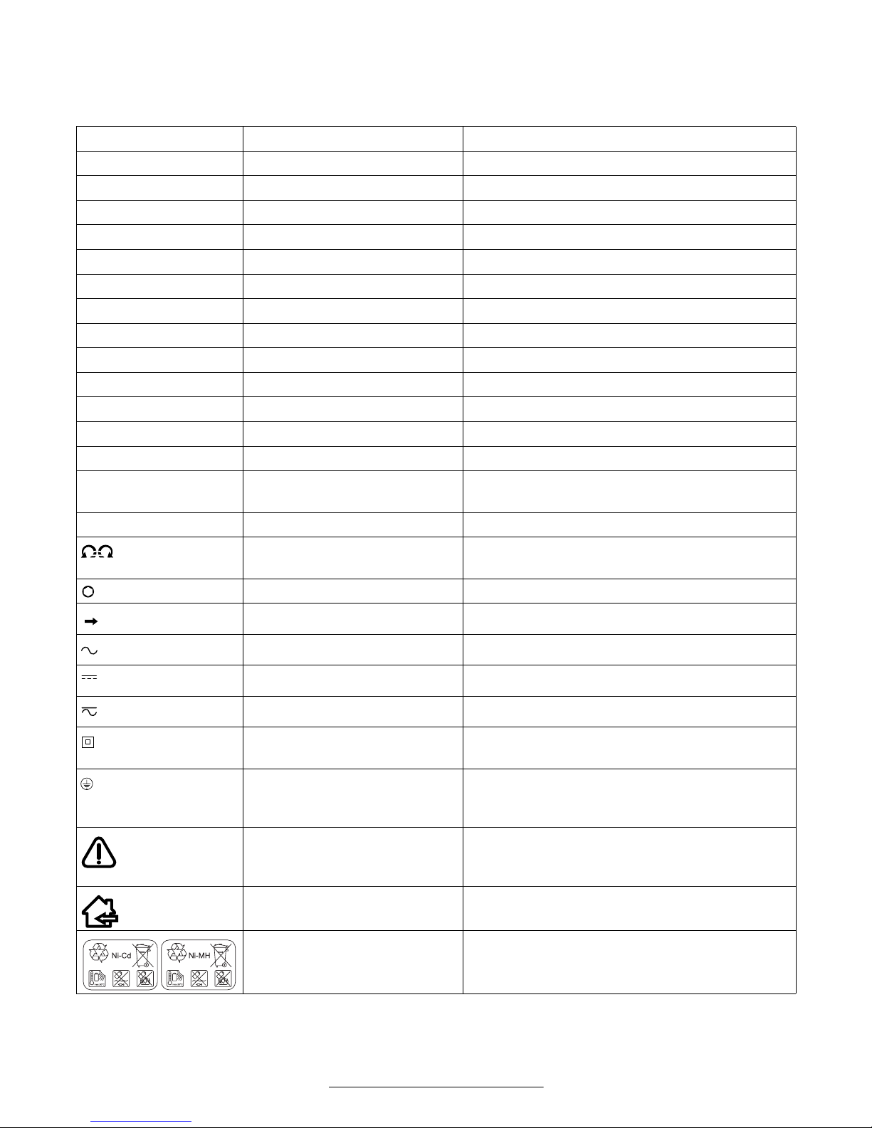
SYMBOLE
Wichtiger Hinweis: Einige der nachfolgenden Symbole können für den Gebrauch Ihres Gerätes von Bedeutung
sein. Prägen Sie sich bitte die Symbole und ihre Bedeutung ein. Die richtige Interpretation der Symbole hilft Ihnen, das Gerät besser und sicherer zu gebrauchen.
Symbol Name Bedeutung
V Volt Elektrische Spannung
A Ampere Elektrische Stromstärke
Ah Ampere Stunde Kapazität, gespeicherte elektrische Energiemenge
Hz Hertz Frequenz
W Watt Leistung
Nm Newtonmeter Energieeinheit, Drehmoment
kg Kilogramm Masse, Gewicht
mm Millimeter Länge
min/s Minuten/Sekunden Zeitspanne, Dauer
°C/°F Grad Celsius/Grad Fahrenheit Temperatur
dB Dezibel Bes. Maß der relativen Lautstärke
Ø Durchmesser z.B. Schraubendurchmesser,
Schleifscheibendurchmesser etc.
min
-1
/n
0
Drehzahl Drehzahl im Leerlauf
…/min Umdrehungen oder
Bewegungen pro Minute
Umdrehungen, Schläge, Kreisbahnen etc.
pro Minute
0 Position: Aus Keine Geschwindigkeit, kein Drehmoment
Linkslauf/Rechtslauf Drehrichtung
/ ■
Innensechskant/Außenvierkant Art der Werkzeugaufnahme
Pfeil Handlung in Pfeilrichtung ausführen
Wechselstrom Strom- und Spannungsart
Gleichstrom Strom- und Spannungsart
Wechsel- oder Gleichstrom Strom- und Spannungsart
Schutzklasse II Geräte der Schutzklasse II sind vollständig isoliert.
Schutzklasse I
lt. DIN: Schutzerde (Schutzleiter)
Geräte der Schutzklasse I müssen in gewissen
Fällen geerdet werden.
Warnhinweis Weist den Benutzer auf die korrekte Handhabung
des Gerätes hin oder warnt vor Gefahren.
Haus Halten Sie das Elektrowerkzeug von Regen oder
Nässe fern.
Nickel-CadmiumAkkumulatoren/Nickel-Metallhydrid-Akkumulatoren
Defekte oder verbrauchte Akkus müssen recycelt
oder umweltfreundlich entsorgt werden.
Page 8
Deutsch–5
3 609 929 879 • (03.02) T
3 FUNKTIONSBESCHREIBUNG
Bitte klappen Sie die Ausklappseite mit
der Darstellung des Gerätes auf, und
lassen Sie diese Seite aufgeklappt,
während Sie die Bedienungsanleitung
lesen.
Bestimmungsgemäßer Gebrauch
Das Gerät ist bestimmt zum Eindrehen und Lösen von
Schrauben sowie zum Anziehen und Lösen von Muttern
im angegebenen Abmessungs- und Leistungsbereich.
Geräusch-/Vibrationsinformation
Messwerte für Geräusch ermittelt entsprechend EN
ISO 15 744. Messunsicherheit 3 dB(A).
Messwerte für Vibration ermittelt entsprechend EN
28 662 und EN ISO 8662.
Der A-bewertete Schalldruckpegel des Gerätes beträgt typischerweise 70 dB(A). Der Geräuschpegel
beim Arbeiten kann 85 dB(A) überschreiten.
Gehörschutz tragen!
Die Hand-Arm-Beschleunigung ist typischerweise
niedriger als 2,5 m/s
2
. Messunsicherheit K = 1,2 m/s
2
.
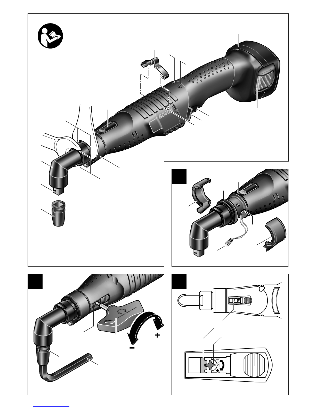
Geräteelemente
Die Nummerierung der Geräteelemente bezieht sich
auf die Darstellung des Gerätes auf der Ausklappseite.
1
Einsatzwerkzeug (z.B. Schraubernuss)*
2
Werkzeugaufnahme
3
Winkelschraubkopf
4
Gabelschlüssel (SW 27)
5
Schlüsselfläche am Winkelkopfflansch
6
Gabelschlüssel (SW 22)
7
Schieber (Drehmomenteinstellung)
8
Aufhängebügel
9
LED-Anzeige Verschraubung
10
LED-Anzeige Akku-Ladezustand
11
Akku-Pack*
12
Akku-Pack-Entriegelungstaste
13
Ein-Aus-Schalter
14
Rechts-Links-Umschaltung mit Einschaltsperre
15
Schlitze für Aufhängebügel
16
LED-Halter
17
Schlüsselfläche an der Überwurfmutter
18
Markierungsring
19
Sprengring
20
Hohlraum in der Gehäuseschale
21
LED-Arbeitslicht
22
Einstellscheibe zum Einstellen des Drehmoments
23
Einstellwerkzeug
24
Sechskant-Stiftschlüssel
* Zubehör
Abgebildetes oder beschriebenes Zubehör gehört teilweise nicht zum Lieferumfang.
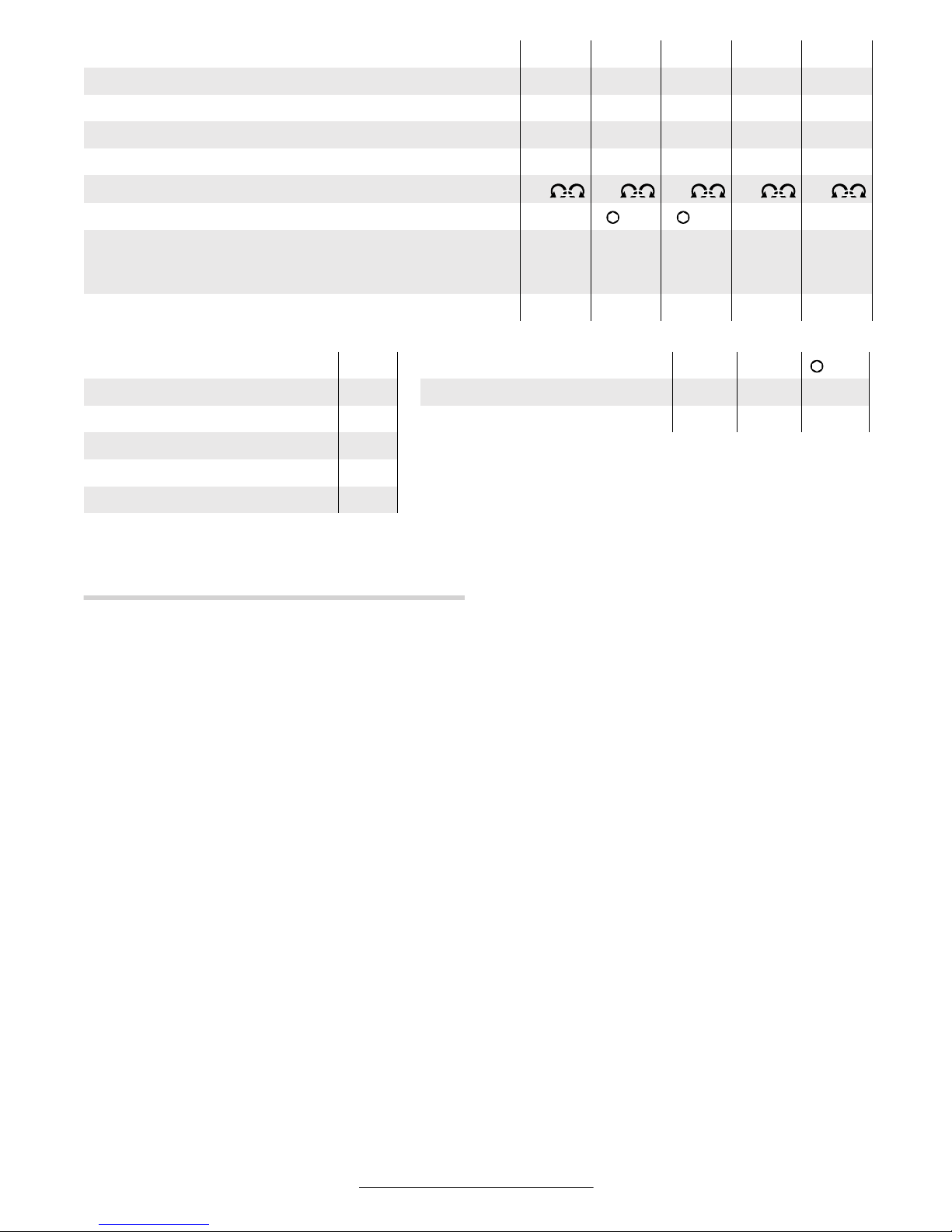
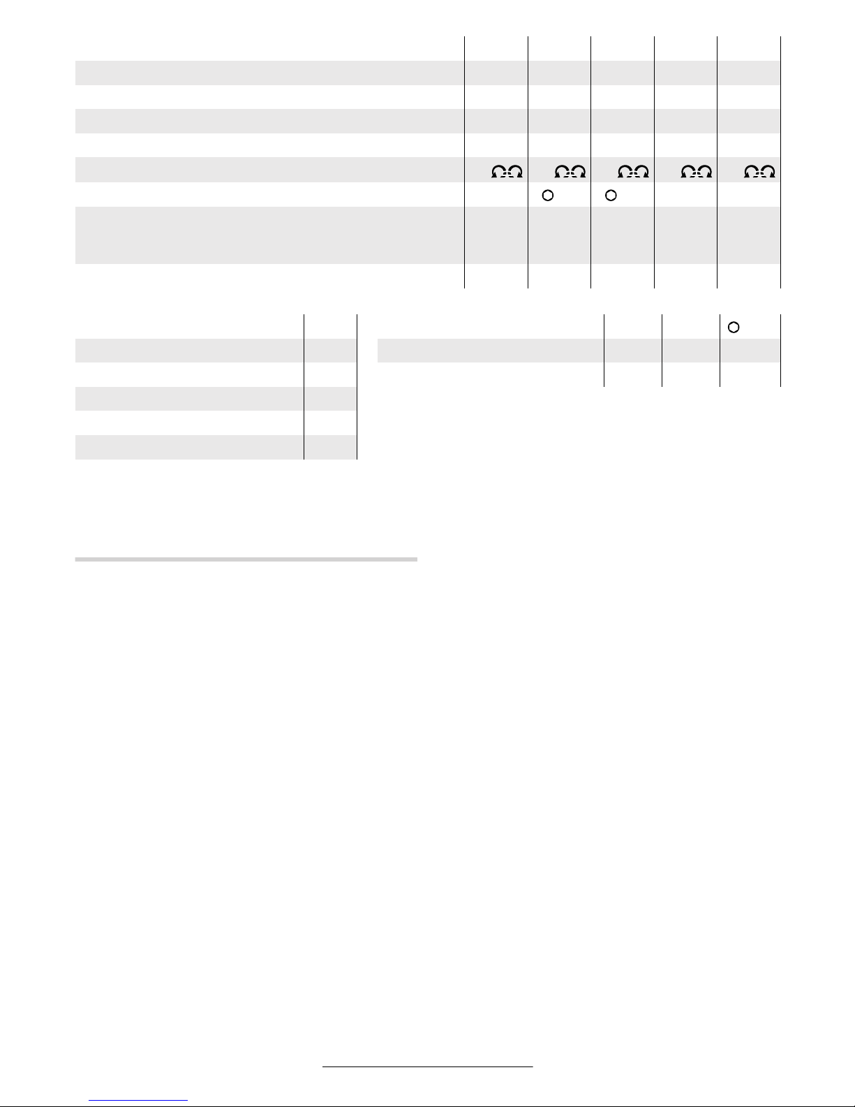
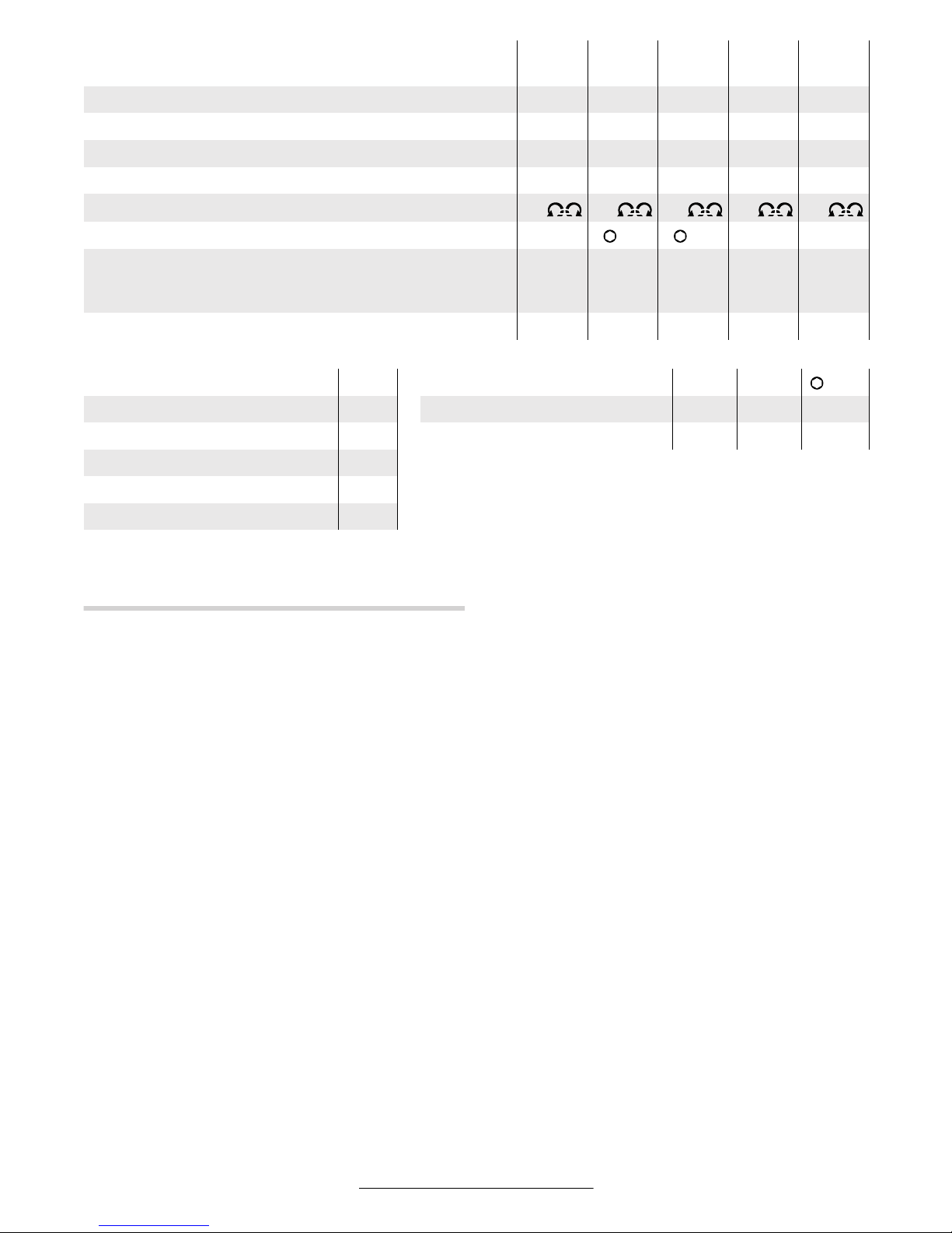
Gerätekennwerte
Industrie-Akku-Winkelschrauber 15 15888
Bestellnummer 0 602 490 ...
... 635 ... 636 ... 637 ... 638 ... 643
Drehmoment [Nm] 15 15888
Leerlaufdrehzahl [min
-1
]
250 250 420 420 420
Spannung [V] 9,6 9,6 9,6 9,6 9,6
Drehrichtung
Werkzeugaufnahme
■
3/8" ■ 3/8" ■ 3/8" ■ 3/8" ■ 1/4"
Lieferumfang
Akku-Pack
Winkelschraubkopf
–
●
●
●
–
●
●
●
–
●
Gewicht (ohne Zubehör) ca. [kg] 1,2 1,7 1,2 1,7 1,2
Page 9
Deutsch–6
3 609 929 879 • (03.02) T
4 BETRIEB
Vor der Inbetriebnahme
Beachten Sie bitte, dass der Akku bei der Lieferung
nicht in das Gerät eingesetzt ist.
Bewahren Sie Akkus nie in einem Akkugerät auf.
Akkus halten länger und lassen sich besser aufladen,
wenn sie separat aufbewahrt werden. Denken Sie daran, den Akku nach längerer Aufbewahrung vor Gebrauch voll aufzuladen.
Akku laden
Laden Sie den Akku vor dem Einsetzen in das Gerät in
einem dafür geeigneten Ladegerät auf. Die genaue
Beschreibung des Ladevorgangs entnehmen Sie bitte
der Bedienungsanleitung des Ladegeräts.
Der Akku ist mit einer NTC-Temperaturüberwachung
ausgestattet, welche Ladung nur im Temperaturbereich zwischen 0 °C (+32 °F) und 45 °C (+113 °F) zulässt. Dadurch wird eine hohe Akku-Lebensdauer erreicht. Bei richtigem Gebrauch kann der Akku bis zu
3000-mal wieder aufgeladen werden.
Ein neuer oder längere Zeit nicht verwendeter Akku
bringt erst nach ca. 5 Lade- und Entladezyklen seine
volle Leistung.
Sie sollten den Akku nach kurzzeitiger Beanspruchung
(z.B. 3 Minuten) nicht erneut laden, um ihn zu schonen.
Akku einsetzen
Drücken Sie die Rechts-Links-Umschaltung 14 in die
mittlere Position, um die Einschaltsperre zu aktivieren,
und stellen Sie den Ein-Aus-Schalter 13 in die Position
„Aus“. Sie verhindern so das unbeabsichtigte Einschalten des Gerätes.
Schieben Sie den geladenen Akku 11 von unten in den
Griff des Gerätes. Achten Sie darauf, den Akku richtig
herum einzuschieben und dass er spürbar im Griff einrastet.
Einsatzwerkzeug einsetzen
Typ 0 602 490 635 / … 636 / … 637 / … 638
Drücken Sie den Stift am Vierkant der Werkzeugaufnahme 2, z.B. mit Hilfe eines schmalen Schraubendrehers, nach innen und schieben Sie das Einsatzwerkzeug 1 über den Vierkant. Achten Sie darauf, dass der
Stift in die Aussparung des Einsatzwerkzeugs einrastet.
Typ 0 602 490 639 / … 640
Stecken Sie das Einsatzwerkzeug 1 in den Innensechskant der Werkzeugaufnahme 2, bis es spürbar einrastet.
Einsatzwerkzeug entfernen
Typ 0 602 490 635 / … 636 / … 637 / … 638
Drücken Sie den Stift in der Aussparung des Einsatzwerkzeugs 1 nach innen, und ziehen Sie das Einsatzwerkzeug von der Werkzeugaufnahme 2.
Industrie-Akku-Winkelschrauber 86666
Bestellnummer 0 602 490 ... ... 644 ... 639 ... 640 ... 641 ... 642
Drehmoment [Nm]86666
Leerlaufdrehzahl [min-1] 420 650 650 650 650
Spannung [V] 9,6 9,6 9,6 9,6 9,6
Drehrichtung
Werkzeugaufnahme ■ 1/4" 1/4" 1/4" ■ 1/4" ■ 1/4"
Lieferumfang
Akku-Pack
Winkelschraubkopf
●
●
–
●
●
●
–
●
●
●
Gewicht (ohne Zubehör) ca. [kg] 1,7 1,2 1,7 1,2 1,7
NiCd-Akku-Pack 9,6 Winkelschraubköpfe ■ 1/4" ■ 3/8" 1/4"
Bestellnummer 2 607 335 ... ... 373 Bestellnummer 0 607 453 ... ... 617 ... 620 ... 618
Zellenzahl 8 Gewicht ca. [kg] 0,2 0,2 0,2
Akku-Spannung [V] 9,6
Kapazität [Ah] 1,7
Gewicht ca. [kg] 0,4
Page 10
Deutsch–7
3 609 929 879 • (03.02) T
Typ 0 602 490 639 / … 640
Ziehen Sie das Einsatzwerkzeug 1 von der Werkzeugaufnahme 2, notfalls mit Hilfe einer Zange.
Aufhängevorrichtung
Mit dem Aufhängebügel 8 können Sie das Gerät an einer Aufhängevorrichtung befestigen.
Setzen Sie den als Zubehör beigelegten Aufhängebügel 8 auf das Gerät auf, und lassen Sie ihn in die Schlitze 15 einrasten.
Kontrollieren Sie regelmäßig den Zustand des Aufhängebügels und der Haken in der Aufhängevorrichtung.
Inbetriebnahme
Wenn Sie das Gerät starten wollen, sollten Sie zunächst die Drehrichtung mit der Rechts-Links-Umschaltung 14 einstellen, da das Gerät nur startet, wenn
die Rechts-Links-Umschaltung 14 nicht in der Mitte
(Einschaltsperre) steht.
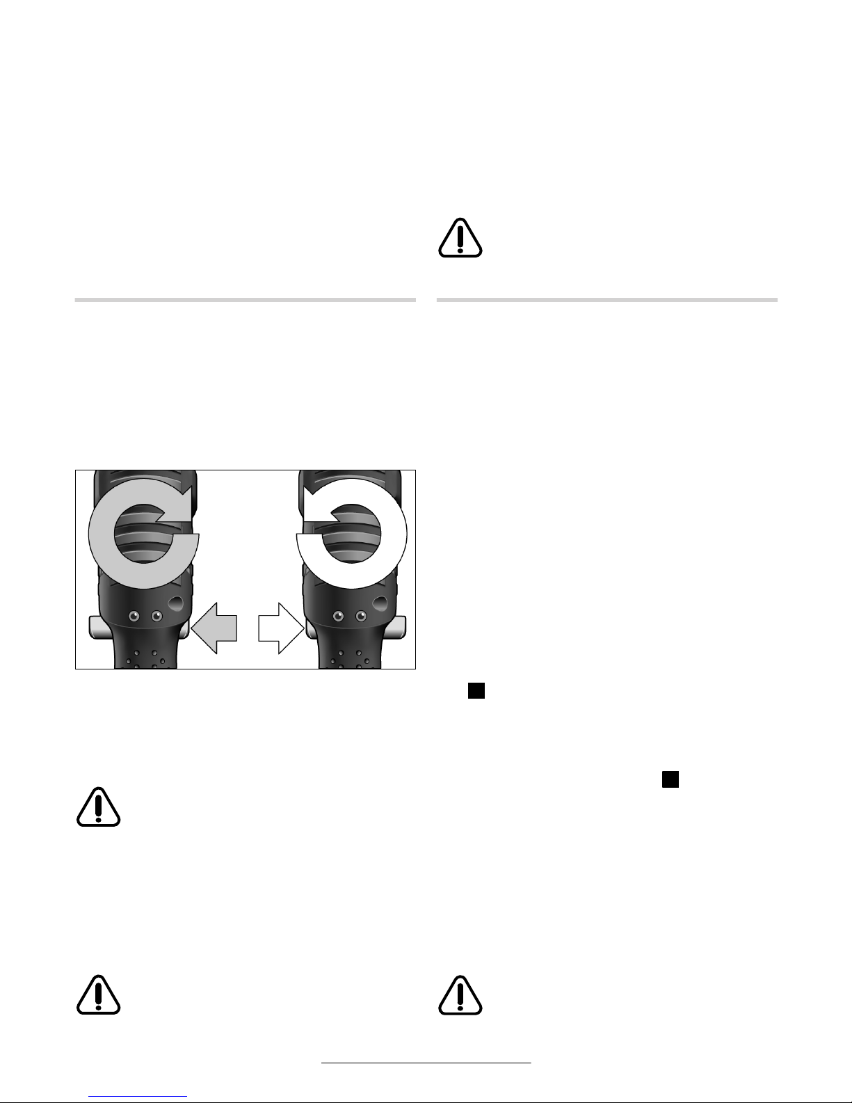
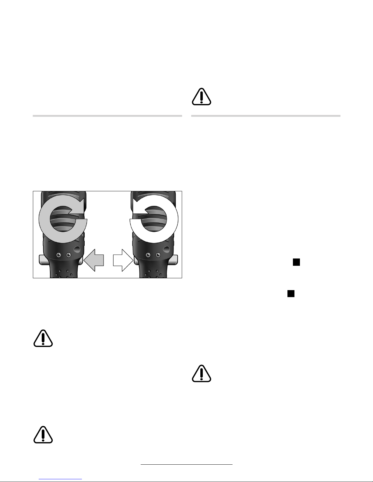
Drehrichtung einstellen
Rechtslauf: Drücken Sie die Rechts-Links-Umschal-
tung 14 bis zum Anschlag nach links (Eindrehen von Schrauben).
Linkslauf: Drücken Sie die Rechts-Links-Umschal-
tung 14 bis zum Anschlag nach rechts (Lö-
sen bzw. Herausdrehen von Schrauben).
Betätigen Sie die Rechts-Links-Umschaltung 14 nur bei Stillstand des Geräts.
LED-Arbeitslicht einschalten
Das Arbeitslicht 21 ermöglicht das Ausleuchten der
Schraubstelle bei ungünstigen Lichtverhältnissen. Sie
schalten das Arbeitslicht 21 durch leichtes Drücken
des Ein-Aus-Schalters 13 ein. Wenn Sie den Ein-AusSchalter 13 fester drücken, wird das Gerät eingeschaltet und das Arbeitslicht 21 leuchtet weiter.
Blicken Sie nicht direkt in das Arbeitslicht, es kann Sie blenden!
Ein-Aus-Schalten
Die Geräte haben eine vom Drehmoment abhängige
Abschaltkupplung, die im angegebenen Bereich einstellbar ist. Sie spricht an, wenn das eingestellte Drehmoment erreicht ist.
Einschalten: Drücken Sie den Ein-Aus-Schalter 13
bis zum Anschlag. Das Gerät schaltet
automatisch beim Erreichen des eingestellten Drehmoments ab.
Ausschalten: Lassen Sie den Ein-Aus-Schalter 13 los.
Bei vorzeitigem Loslassen des Ein-Aus-Schalters 13 wird das voreingestellte Drehmoment
nicht erreicht.
Arbeitshinweise
Entfernen Sie den Akku aus dem Gerät, bevor Sie
Geräteeinstellungen vornehmen, Zubehörteile
wechseln oder das Gerät lagern. Diese Vorsichts-
maßnahme verhindert eine unbeabsichtigte Inbetriebnahme des Gerätes.
Akku entnehmen
Der Akku 11 ist im Griff der Maschine untergebracht.
Drücken Sie auf beiden Seiten auf die Entriegelungs-
tasten 12 und ziehen Sie den Akku 11 nach unten aus
dem Griff. Keine Gewalt anwenden.
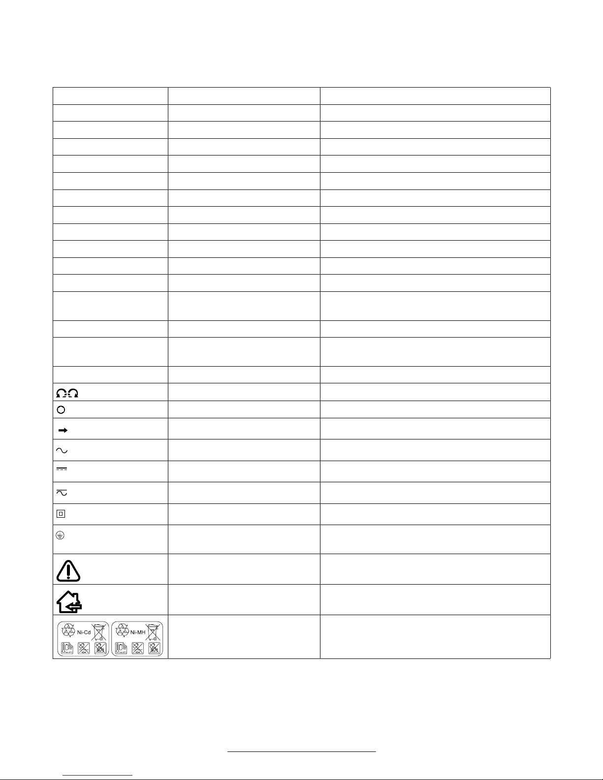
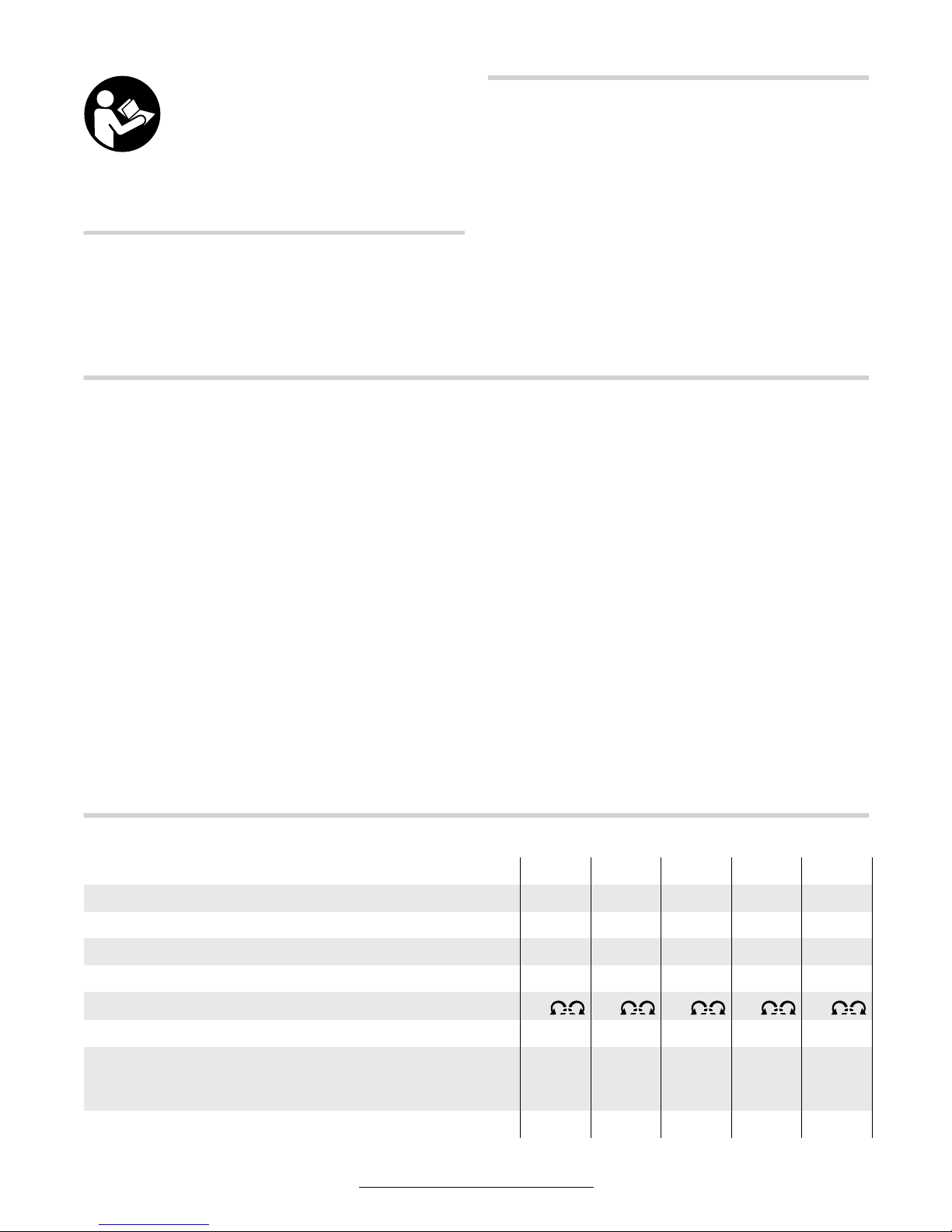
Drehmoment einstellen
Das Drehmoment hängt von der Federvorspannung
der Abschaltkupplung ab. Die Abschaltkupplung löst
sowohl im Rechts- als auch im Linkslauf bei Erreichen
des eingestellten Drehmoments aus.
Zum Einstellen des individuellen Drehmoments nur
das mitgelieferte Einstellwerkzeug 23 verwenden
(Bild ).
Schieben Sie den Schieber 7 am Gerät komplett zurück. Stecken Sie den Sechskant-Stiftschlüssel 24 in
das Einsatzwerkzeug 1 und drehen Sie ihn langsam,
bis in der Gehäuseöffnung eine kleine Ausbuchtung in
der Kupplung zu erkennen ist (Bild ). In diese Ausbuchtung das Einstellwerkzeug 23 stecken und das
Einstellwerkzeug 23 drehen.
Drehen im Uhrzeigersinn ergibt ein höheres Drehmoment, Drehen gegen den Uhrzeigersinn ein niedrigeres
Drehmoment.
Hinweis: Die erforderliche Einstellung ist von der Art
der Schraubverbindung abhängig und lässt sich am
besten im praktischen Versuch ermitteln. Probeverschraubung mit einem Drehmomentschlüssel überprüfen.
Stellen Sie das Drehmoment nur im angegebenen Leistungsbereich ein, da sonst
die Abschaltkupplung nicht mehr anspricht.
14
B
C
Page 11
Deutsch–8
3 609 929 879 • (03.02) T
Drehmomenteinstellung markieren
Zur Kennzeichnung individuell eingestellter Drehmomente können Sie den Markierungsring 18 gegen einen andersfarbigen Markierungsring austauschen.
Drücken Sie den Markierungsring 18 mit einem dünnen Schraubendreherblatt, einer Spachtel oder Ähnlichem ab.
Benutzen Sie das Gerät immer mit einem Markierungsring, da sonst das Gehäuse des Gerätes nicht
mehr geschlossen ist.
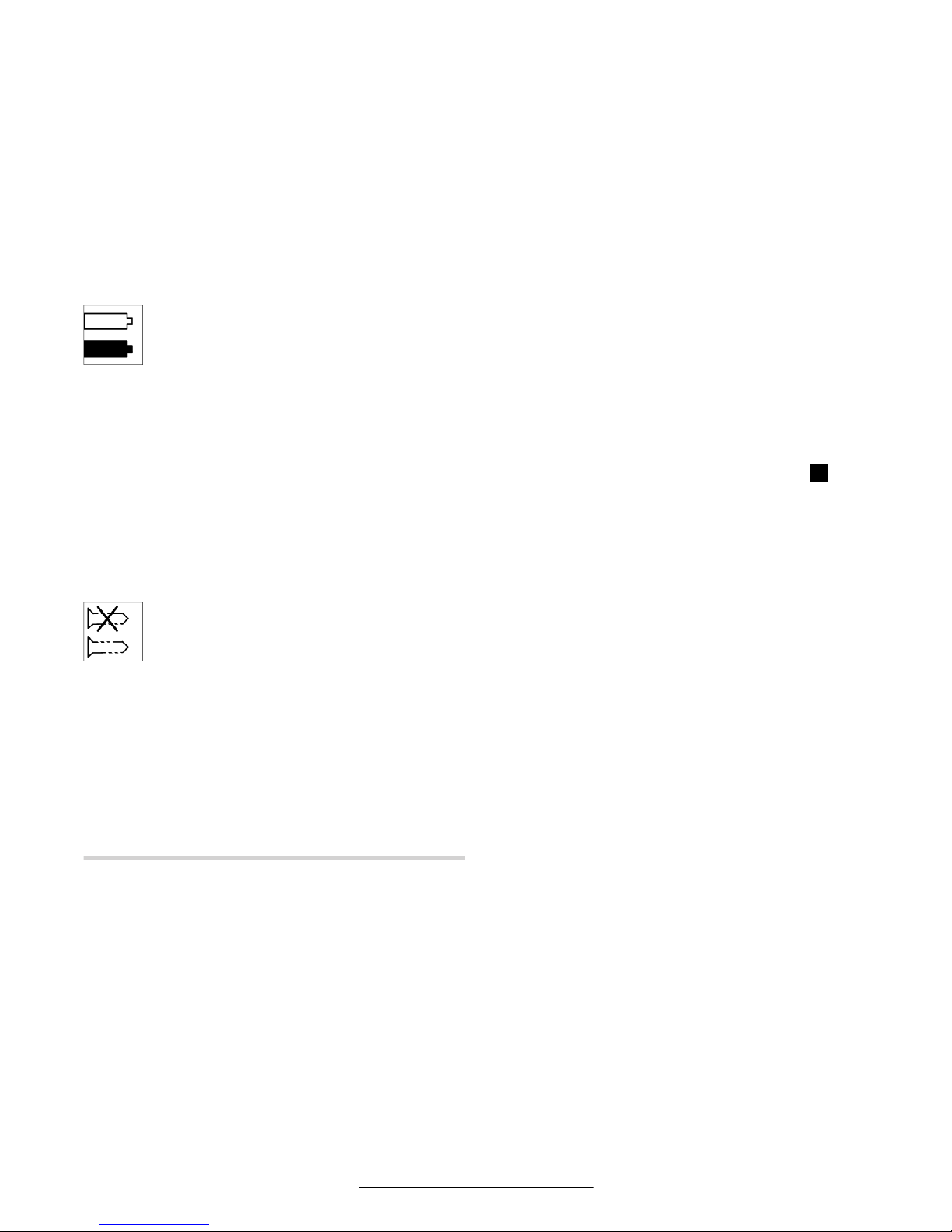
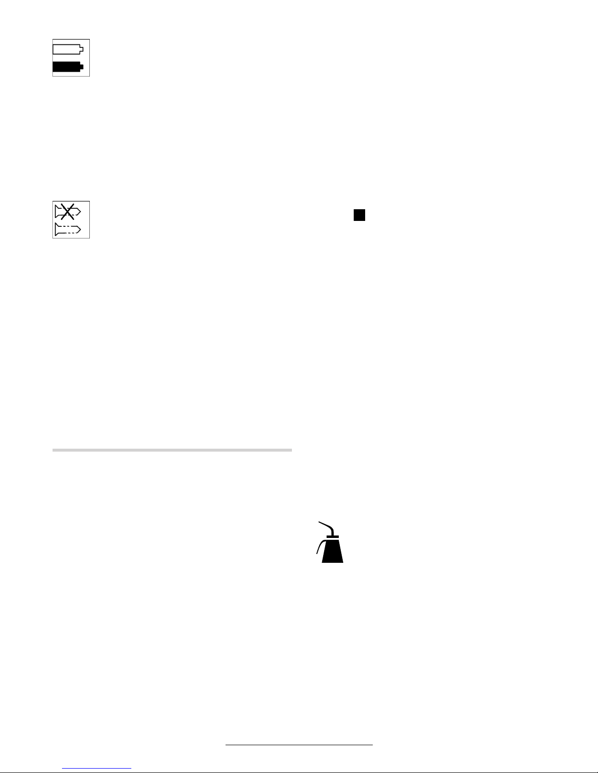
LED-Anzeige
Anzeige Akku-Ladezustand
Ist das Laden des Akkus 11 erforderlich,
blinkt die LED-Anzeige 10 grün. Sie können
das Gerät noch für ca. 6–8 Verschraubun-
gen verwenden.
Leuchtet die LED-Anzeige rot, reicht die Kapazität nicht
mehr für eine neue Verschraubung. Das Gerät kann
nicht mehr eingeschaltet werden. Die Einschaltsperre
bleibt aktiv, bis ein geladener Akku eingesetzt wird.
Eine wesentlich verkürzte Betriebszeit des Geräts
nach jeder Aufladung zeigt an, dass der Akku bald ersetzt werden muss. Entsorgen Sie verbrauchte Akkus
gemäß den gesetzlichen/länderspezifischen Bestimmungen.
Anzeige Verschraubung
Bei Erreichen des voreingestellten Drehmo-
ments löst die Abschaltkupplung aus. Die
LED-Anzeige 9 leuchtet grün.
Wurde das voreingestellte Drehmoment nicht erreicht,
leuchtet die LED-Anzeige 9 rot auf, und es ertönt ein
akustisches Signal. Die Verschraubung muss noch
einmal durchgeführt werden.
Wiederholschutz
Wurde bei einer Verschraubung die Abschaltkupplung
ausgelöst, schaltet der Motor ab. Ein Wiedereinschalten ist erst nach 0,7 Sekunden Pause möglich. Sie
vermeiden dadurch ein versehentliches Nachziehen
bereits fester Verschraubungen.
Verstellen des Winkelschraubkopfes
Sie können den Winkelschraubkopf 3 in insgesamt
acht Positionen verstellen.
Halten Sie das Gerät mit dem Gabelschlüssel 6 an der
Schlüsselfläche 5 des Winkelkopfflansches fest.
Gerät nie an den Gehäuseschalen einspannen!
Lösen Sie mit dem Gabelschlüssel 4 an der Schlüsselfläche 17 die Überwurfmutter. Verstellen Sie den Winkelschraubkopf 3 um jeweils 45° in die gewünschte
Position, und drehen Sie mit dem Gabelschlüssel 4 an
der Schlüsselfläche 17 die Überwurfmutter wieder
fest. Dabei mit dem Gabelschlüssel 6 am Winkelflansch gegenhalten.
LED-Arbeitslicht verstellen (siehe Bild )
Drücken Sie den Markierungsring 18 mit einem dünnen Schraubendreherblatt, einer Spachtel oder Ähnlichem ab. Schieben Sie den Sprengring 19 mit einer
Sprengringzange nach hinten auf die Gehäuseschale.
Die beiden Schalenhälften des LED-Halters 16, die das
LED-Arbeitslicht 21 umschließen, lassen sich nun in
jede gewünschte Position bringen. Achten Sie darauf,
das Kabel am LED-Arbeitslicht nicht zu beschädigen
und schieben Sie es, ohne es zu knicken, in den dafür
vorgesehenen Hohlraum 20 in der Gehäuseschale.
Umschließen Sie das LED-Arbeitslicht 21 wieder mit
den beiden Gehäuseschalen des LED-Halters 16. Drücken Sie den Sprengring 19 und den Markierungsring
18 wieder zurück in die ursprüngliche Position.
5 WARTUNG UND SERVICE
Wartung
Entfernen Sie den Akku aus dem Gerät, bevor Sie
Geräteeinstellungen vornehmen, Zubehörteile
wechseln oder das Gerät lagern. Diese Vorsichts-
maßnahme verhindert eine unbeabsichtigte Inbetriebnahme des Gerätes.
Wenn der Akku nicht benötigt wird, bewahren
Sie ihn fern von metallenen Gegenständen wie
Papierklammern, Münzen, Schlüsseln, Nägeln,
Schrauben oder Ähnlichem auf, die eine Überbrückung zwischen den einzelnen Kontakten
herstellen könnten. Eine metallische Überbrückung
kann einen Kurzschluss, Funkenschlag oder Feuer
verursachen.
Sollte das Gerät trotz sorgfältiger Herstell- und Prüfverfahren einmal ausfallen, ist die Reparatur von einer
autorisierten Kundendienststelle für Bosch-Elektrowerkzeuge ausführen zu lassen.
Geben Sie bitte bei allen Rückfragen und Ersatzteilbestellungen die 10-stellige Bestellnummer laut Typenschild des Gerätes an.
Nach ca. 150 Betriebsstunden ist das Getriebe erstmals zu reinigen, dann alle 300 Betriebsstunden. Nach
jeder Reinigung sollte es mit Spezial-Getriebefett geschmiert werden.
Die beweglichen Teile der Kupplung sind nach jeweils
ca. 100000 Schraubungen mit einigen Tropfen Motorenöl SAE 10/SAE 20 nachzufetten. Die gleitenden
und rollenden Teile sind mit Molykotefett zu schmieren. Danach Kupplungseinstellung überprüfen.
A
Page 12
Deutsch–9
3 609 929 879 • (03.02) T
Schmieren
Schmierstoff:
Spezial-Getriebefett 225 ml
3 605 430 009
Molykotefett
Motorenöl SAE 10/SAE 20
Lassen Sie Wartungs- und Reparaturarbeiten nur
von qualifiziertem Fachpersonal durchführen.
Damit wird sichergestellt, dass die Sicherheit des Gerätes erhalten bleibt.
Eine autorisierte Bosch-Kundendienststelle führt diese
Arbeiten schnell und zuverlässig aus.
Schmier- und Reinigungsstoffe umweltgerecht
entsorgen. Gesetzliche Vorschriften beachten.
Zubehör
Bosch bietet folgende Ladegeräte für die Akkus an:
AL 15 FC 2498
ML 60-4
Bei der Wahl des geeigneten Ladegeräts hilft Ihnen die
autorisierte Kundendienststelle für Bosch-Elektrowerkzeuge oder Ihr Fachhändler.
Über das komplette Qualitätszubehörprogramm können Sie sich im Internet unter www.bosch-pt.com und
www.boschproductiontools.com oder bei Ihrem
Fachhändler informieren.
Service
Die Robert Bosch GmbH haftet für die vertragsgemäße Lieferung dieser Maschine im Rahmen der gesetzlichen/länderspezifischen Bestimmungen. Bei Beanstandungen an der Maschine wenden Sie sich bitte an
folgende Stelle:
Deutschland
Robert Bosch GmbH
Servicezentrum Elektrowerkzeuge
Zur Luhne 2
37589 Kalefeld-Willershausen
✆ Service . . . . . . . . . . . . . . . . . . (01 80) 3 35 54 99
Fax . . . . . . . . . . . . . . . . . . . . . . . (0 55 53) 20 22 37
✆ Kundenberater . . . . . . . . . . . . (01 80) 3 33 57 99
e-mail: ProductionTools@de. bosch.com
www.boschproductiontools.com
Österreich/Schweiz
Fax . . . . . . . . . . . . . . . . . . . . . +49 (711) 7 58 24 36
www.boschproductiontools.com
Entsorgung
Gerät, Zubehör und Verpackung sollten einer umweltgerechten Wiederverwertung zugeführt werden.
Zum sortenreinen Recycling sind Kunststoffteile gekennzeichnet.
Versuchen Sie nicht, den Akku
auseinander zu bauen oder hervorstehende Teile an den Akkukontakten zu entfernen. Dies könnte zu Feuer oder Verletzungen füh-
ren. Schützen Sie offen liegende Kontakte mit
Isolierband, um einen Kurzschluss zu verhindern, bevor Sie den Akku entsorgen.
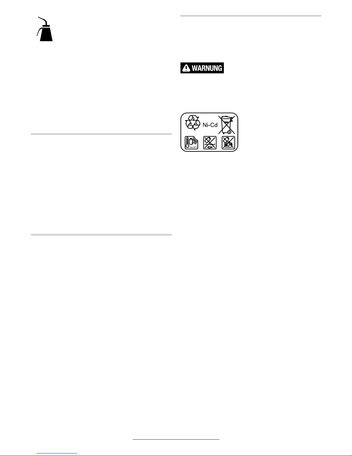
Nickel-Cadmium-Akku:
Wenn Ihr Gerät mit einem Nickel-Cadmium-Akku ausgerüstet ist, muss der Akku gesammelt, recycelt oder auf
umweltfreundliche Weise
entsorgt werden.
Defekte oder verbrauchte Akkus müssen gemäß
Richtlinie 91/157/EWG recycelt werden.
Nicht mehr gebrauchsfähige Akkus/Batterien können
direkt abgegeben werden bei:
Deutschland
Recyclingzentrum Elektrowerkzeuge
Osteroder Landstr. 3
37589 Kalefeld
Schweiz
Batrec AG
3752 Wimmis BE
Darüber hinaus können in Deutschland nicht mehr gebrauchsfähige Geräte zum Recycling beim Handel abgegeben oder (ausreichend frankiert) direkt eingeschickt werden an:
Recyclingzentrum Elektrowerkzeuge
Osteroder Landstr. 3
37589 Kalefeld
Änderungen vorbehalten
Page 13

English–1
3 609 929 879 • (03.02) T
1 GENERAL SAFETY RULES
FOR ALL BATTERY-OPERATED TOOLS
Read all instructions. Failure to follow
all instructions listed below may re-
sult in electric shock, fire and/or serious injury. The term “power tool” in all of the warnings
listed below refers to your mains-operated (corded)
power tool or battery-operated (cordless) power tool.
SAVE THESE INSTRUCTIONS.
Work area
Keep work area clean and well lit. Cluttered and
dark areas invite accidents.
Do not operate power tools in explosive atmospheres, such as in the presence of flammable
liquids, gases or dust. Power tools create sparks
which may ignite the dust or fumes.
Keep children and bystanders away while operating a power tool. Distractions can cause you to
lose control.
Personal safety
Stay alert, watch what you are doing and use
common sense when operating a power tool. Do
not use a power tool while you are tired or under
the influence of drugs, alcohol or medication. A
moment of inattention while operating power tools
may result in serious personal injury.
Use safety equipment. Always wear eye protection. Safety equipment such as dust mask, non-skid
safety shoes, hard hat, or hearing protection used for
appropriate conditions will reduce personal injuries.
Avoid accidental starting. Ensure the switch is in
the off position before inserting battery pack.
Carrying power tools with your finger on the switch or
inserting the battery pack into a power tool with the
switch on invites accidents.
Remove any adjusting key or wrench before
turning the power tool on. A wrench or a key left at-
tached to a rotating part of the power tool may result
in personal injury.
Do not overreach. Keep proper footing and balance at all times. This enables better control of the
power tool in unexpected situations.
Dress properly. Do not wear loose clothing or
jewellery. Keep your hair, clothing and gloves
away from moving parts. Loose clothes, jewellery
or long hair can be caught in moving parts.
If devices are provided for the connection of dust
extraction and collection facilities ensure these
are connected and properly used. Use of these
devices can reduce dust-related hazards.
Power tool use and care
Do not force the power tool. Use the correct
power tool for your application. The correct power
tool will do the job better and safer at the rate for which
it was designed.
Do not use the power tool if the switch does not
turn it on and off. Any power tool that cannot be
controlled with the switch is dangerous and must be
repaired.
Store idle power tools out of the reach of children and do not allow persons unfamiliar with
the power tool or these instructions to operate
the power tool. Power tools are dangerous in the
hands of untrained users.
Maintain power tools. Check for misalignment
or binding of moving parts, breakage of parts
and any other condition that may affect the power tools operation. If damaged, have the power
tool repaired before use. Many accidents are
caused by poorly maintained power tools.
Keep the tool bits clean. Well cared for tool bits are
easier to use and can be controlled better.
Use the power tool, accessories and tool bits
etc., in accordance with these instructions and in
the manner intended for the particular type of
power tool, taking into account the working conditions and the work to be performed. Use of the
power tool for operations different from those intended
could result in a hazardous situation.
Service
Have your power tool serviced by a qualified repair person using only identical replacement
parts. This will ensure that the safety of the power tool
is maintained.
Page 14

English–2
3 609 929 879 • (03.02) T
2 SPECIFIC SAFETY RULES
FOR RECHARGEABLE BATTERIES
Do not put batteries into fire or expose to high
heat. They may explode.
Battery leakage may occur under extreme usage
or temperature conditions. When a rechargeable
battery leaks, avoid contact with the skin or
eyes. The battery liquid is caustic and could cause
chemical burns to tissues. If liquid comes in contact
with skin, wash quickly with soap and water, then with
lemon juice or vinegar. If the liquid contacts your eyes,
flush them with water for a minimum of 10 minutes and
seek medical attention.
A battery-operated tool with integral batteries or
a separate battery pack must be recharged only
with the specified charger for the battery. A
charger that may be suitable for one type of battery
may create a risk of fire when used with another battery.
Be alert for battery packs that are nearing their
end of life. Battery packs typically last from 1,000 to
3,000 charges (depending on charger used). If you
notice decreased tool performance or significantly
shorter running time between charges then it is time to
replace the battery pack. Failure to do so can cause
the tool to operate improperly or damage the charger.
When battery pack is not in use, keep it away
from other metal objects such as: paper clips,
coins, keys, nails, screws, or other small metal
objects that can make a connection from one
terminal to another. Shorting the battery terminals
together may cause sparks, burns, or a fire.
Never store rechargeable batteries in a battery
powered tool. Rechargeable batteries last longer
and are easier to recharge when they are stored separately. Remember to fully recharge batteries that
have been stored for a longer time before use.
FOR CORDLESS DRIVERS
Hold tool by insulated gripping surfaces when
performing an operation where the cutting tools
may contact hidden wiring. Contact with a “live”
wire will make exposed metal parts of the tool “live”
and shock the operator.
Use appropriate detectors to determine if utility
lines are hidden in the work area or call the local
utility company for assistance. Contacting electric
lines may cause fire or electric shock. Striking a gas
line may result in explosion. Breaking into a water pipe
will cause property damage.
Do not expose power tools to rain or wet conditions. Water entering a power tool will increase the
risk of electric shock.
Remove the battery from the power tool before
adjustments are made to the tool, accessories
are changed or the tool is stored. This safety
measure prevents the unintentional switching on of the
power tool.
Take care when inserting a tool bit that the shaft
of the tool bit is seated firmly in the tool holder.
When the shaft of the tool bit is not inserted deeply
enough in the tool holder, the tool bit can slide out and
no longer be controlled.
Use only flawless tool bits that are not worn. De-
fective tool bits can break, for example, and cause injuries or damage.
Use clamps or other practical way to secure and
support the workpiece to a stable platform. Hold-
ing the work by hand or against your body is unstable
and may lead to loss of control.
Be prepared for a reaction torque when “seating” or removing a fastener. The screwdriver hous-
ing may tend to twist in the opposite direction of bit rotation when “seating” or removing a fastener
depending on the torque setting of the tool.
Place the screwdriver tool onto the nut/screw
only when the screwdriver is switched off. Rotat-
ing screwdriver tools can slide off the nut/screw.
Be careful when driving long screws – there is a
risk of sliding off the fastener head depending on
type of socket or bit used. Long screws are often
difficult to control and the danger exists that the tool
slips off when screwing in and causes injuries.
Pay attention to the direction of rotation that is
set before switching on the tool. For example,
when a screw is to be loosened and the direction of rotation is set so that the screw is tightened, this can
lead to a strong uncontrollable movement of the tool.
Do not run the tool while carrying it at your side.
A spinning bit could become entangled with clothing
and injury may result.
Page 15
English–3
3 609 929 879 • (03.02) T
SYMBOLS
Important notice: Some of the following symbols could have meaning for the use of your tool. Please take note
of the symbols and their meaning. The correct interpretation of the symbols will help you to use the tool in a
better and safer manner.
Symbol Name Meaning
V Volts Voltage
A Amperes Current
Ah Ampere-hours Capacity, quantity of stored electrical energy
Hz Hertz Frequency (cycles per second)
W Watt Power
Nm Newton-meter Unit of energy
kg Kilograms Mass, weight
mm Millimeter Length
min/s Minutes/Seconds Time
°C/°F Degrees Celsius/Degrees
Fahrenheit
Temperature
dB Decibel Unit of relative loudness
Ø Diameter Size of drill bits, grinding wheels, etc.
min
-1
/n
0
Revolutions per minute/no load
speed
Rotational speed, at no load
…/min Revolutions or reciprocation per
minute
Revolutions, strokes, surface speed, orbits, etc.
per minute
0 Off position Zero speed, zero torque
Left rotation/Right rotation Direction of Drive Rotation
/ ■
Hex socket drive/Square drive Type of tool holder
Arrow Action in the direction of arrow
Alternating current Type or a characteristic of current
Direct current Type or a characteristic of current
Alternating or direct current Type or a characteristic of current
Class II construction Designates double insulated construction tools.
Protection class I
(Earthing terminal)
Grounding terminal
Warning symbol Alerts user to warning messages. Read and under-
stand instructions before operation.
House Do not expose power tools to rain or wet condi-
tions.
Ni-Cd RBRC™ seal Designates Ni-Cd battery recycling program
Page 16

English–4
3 609 929 879 • (03.02) T
3 FUNCTION
Please open the fold-out page with the
illustration of the unit and leave it open
while you read these operating instructions.
Intended Use
The tool is intended for the screwing in and loosening
of bolts and screws as well as for the tightening and
loosening of nuts in the specified dimension and performance range.
Noise/Vibration Information
Measured sound values determined in accordance
with EN ISO15 744. Measuring inaccuracy 3 dB(A).
Measured vibrational values determined in accordance with EN 28 662 and EN ISO 8662.
The A-weighted sound pressure level of the product is
typically 70 dB(A). The noise level when working can
exceed 85 dB(A).
Wear ear protection!
The hand-arm-acceleration is typically below 2.5 m/s
2
.
Measuring inaccuracy K = 1.2 m/s
2
.
Product Elements
The numbering of the product elements refers to the
illustration on the fold-out page.
1
Insertion tool (e.g. socket nut)*
2
Tool holder
3
Angled drive head
4
Open-ended spanner (27 mm)
5
Spanner flats on the angled head flange
6
Open-ended spanner (22 mm)
7
Slide (torque setting)
8
Hanging hoop
9
LED indicator, tightening control
10
LED Indicator, battery condition
11
Battery-pack*
12
Battery release button
13
On/Off switch
14
Right/Left switching with centre lock
15
Slots for hanging hoop
16
LED holder
17
Spanner flats on the sleeve nut
18
Coloured ring (for identifying torque range)
19
Spring ring
20
Cavity in the housing shell
21
LED work area illumination lamp
22
Adjustment disc for the setting of the torque
23
Adjustment tool
24
Allen key
* Optional accessories
Not all the accessories illustrated or described are included in standard delivery.
Product Specifications
Industrial Cordless Angle Wrench 15 15888
Order number 0 602 490 ...
... 635 ... 636 ... 637 ... 638 ... 643
Tightening torque [Nm] 15 15888
No-load speed [min
-1
]
250 250 420 420 420
Voltage [V] 9.6 9.6 9.6 9.6 9.6
Rotational direction
Tool holder
■
3/8" ■ 3/8" ■ 3/8" ■ 3/8" ■ 1/4"
Delivered items
Battery-pack
Angled drive head
–
●
●
●
–
●
●
●
– ●
Weight (without accessories) approx. [kg] 1.2 1.7 1.2 1.7 1.2
Page 17
English–5
3 609 929 879 • (03.02) T
4 OPERATING INSTRUCTIONS
Before Use
Please take note that the battery is not inserted in the
power tool when delivered.
Never store rechargeable batteries in a battery
powered tool. Rechargeable batteries last longer
and are easier to recharge when they are stored separately. Remember to fully recharge batteries that
have been stored for a longer time before use.
Charging the Battery
Charge the battery before inserting into the power tool
with a suitable charging unit. The exact description of
the charging procedure can be found in the operating
instructions of the charging unit.
The battery is equipped with a NTC temperature sensor
that allows charging only in the temperature range between 0 °C (+32 °F ) and 45 °C (+113 °F). A long service
life of the battery is achieved in this manner. With correct
usage, the battery can be recharged up to 3000 times.
A new battery or a battery that has not been used for
a longer time produces full power only after approximately five charge/discharge cycles.
You should not recharge a battery after brief usage
(e.g., 3 minutes) in order to protect it.
Inserting the Battery
Press the right/left switch 14 to the middle position to
activate the switch-on lock and place the on/off switch
13 in the “off” position. This prevents the unintentional
switching on of the tool.
Slide the charged battery 11 from below into the handle of the power tool. Take care that the battery is in
the correct position when sliding in and that it can be
felt to engage in the handle.
Attaching the Insertion Tool
Type 0 602 490 635 / … 636 / … 637 / … 638
Press in the pin on the drive square of the tool holder
2, e.g., with the aid of a small screwdriver and slide the
insertion tool 1 over the drive square. Take care that
the pin engages in the recess of the insertion tool.
Type 0 602 490 639 / … 640
Insert the insertion tool 1 into the hex-socket of the
tool holder 2 until it can be felt to engage.
Removing the Insertion Tool
Type 0 602 490 635 / … 636 / … 637 / … 638
Press in the pin in the recess of the insertion tool 1 and
pull the insertion tool off of the tool holder 2.
Industrial Cordless Angle Wrench 86666
Order number 0 602 490 ... ... 644 ... 639 ... 640 ... 641 ... 642
Tightening torque [Nm]86666
No-load speed [min-1] 420 650 650 650 650
Voltage [V] 9.6 9.6 9.6 9.6 9.6
Rotational direction
Tool holder ■ 1/4" 1/4" 1/4" ■ 1/4" ■ 1/4"
Delivered items
Battery-pack
Angled drive head
●
●
–
●
●
●
–
●
●
●
Weight (without accessories) approx. [kg] 1.7 1.2 1.7 1.2 1.7
Ni-Cd Battery Pack 9.6 Angled Drive Heads ■ 1/4" ■ 3/8" 1/4"
Order number 2 607 335 … … 373 Order number 0 607 453 … … 617 … 620 … 618
Number of cells 8 Weight approx. [kg] 0.2 0.2 0.2
Battery voltage [V] 9.6
Capacity [Ah] 1.7
Weight approx. [kg] 0.4
Page 18
English–6
3 609 929 879 • (03.02) T
Type 0 602 490 639 / … 640
Pull the insertion tool 1 off of the tool holder 2 with the
aid of pliers, if necessary.
Suspension Device
With the hanging hoop 8, the machine can be attached to a suspension device.
Place the hanging hoop 8 included as an accessory on
the machine and allow it to engage in the slots 15.
Regularly check the condition of the hanging hoop and
the hook of the suspension device.
Putting into Operation
When starting the power tool, you should first select
the direction of rotation with the right/left rotation
switch 14 since the power tool starts only when the
right/left rotation switch 14 is not in the middle position
(switch-on lock).
Setting the Direction of Rotation
Right rotation: Press the right/left rotation switch 14 to
the left to the stop (Screwing in of
screws).
Left rotation: Press the right/left rotation switch 14 to
the right to the stop (Loosening or unscrewing of screws).
Operate the right/left rotation switch 14
only when the power tool is at a standstill.
Switching on the LED Work Area Illumination
Lamp
The work area lamp 21 makes possible the lighting of
the screwing position for unfavourable light conditions.
The work area lamp 21 is switched on by lightly pressing the on/off switch 13. When the on-off switch 13 is
firmly pressed, the power tool is switched on and the
work area lamp 21 continues to light.
Do not look directly into the work area
lamp – your sight can be temporarily degraded!
Switching On/Off
The tools have a torque dependent switch-off coupling that is adjustable in the specified range. It re-
sponds when the torque that is set is reached.
Switching on: Press the on/off switch 13 to the stop.
The tool switches off automatically
when the adjusted torque setting is
reached.
Switching off: Release the on/off switch 13.
When the on/off switch 13 is released prematurely, the pre-set torque is not reached.
Working Instructions
Remove the battery from the power tool before adjustments are made to the tool, accessories are
changed or the tool is stored. This safety measure
prevents the unintentional switching on of the power tool.
Removing the Battery
The battery 11 is located in the handle of the power tool.
Press the unlocking buttons 12 on both sides and pull
the battery 11 downward out of the handle. Do not use
force.
Setting the Torque
The tightening torque is dependent on the spring pretension of the switch-off coupling. The switch-off coupling responds in right as well as left rotation when the
torque setting is reached.
For setting the individual tightening torques, use only
the adjustment tool 23 provided (Fig. ).
Push the slide 7 on the power tool completely back. Insert the Allen key 24 into the insertion tool 1 and turn
slowly until a small indentation in the coupling is visible
in the opening in the housing (Fig. ). Insert the adjustment tool 23 into this indentation and turn the adjustment tool 23.
Turning in the clockwise direction results in a higher
torque, in the counter clockwise direction, a lower toque.
Note: The required adjustment is dependent on the
type of threaded connection and can be best determined by practical trials. Check the trial screwings with
a torque wrench.
Set the torque only in the specified performance range, otherwise the shut-off
coupling will no longer respond.
Marking the Torque Setting
To identify individually adjusted tightening torques, the
marking ring 18 can be replaced with a marking ring of
another colour. Press off the marking ring 18 with a
thin screwdriver blade, a knife or similar.
Always use the power tool with a marking ring since
otherwise the housing is no longer closed.
14
B
C
Page 19
English–7
3 609 929 879 • (03.02) T
LED Indicators
Battery Condition Indicator
If the charging of the battery 11 is necessary,
the LED indicator 10 blinks green. You can
still use the power tool for approx. 6–8
screwing actions.
If the LED indicator lights red, the capacity is no longer
adequate for another screwing action. The power tool
can no longer be switched on. The switch-on lock remains active until a charged battery is inserted.
A considerably shortened operating time of the power
tool after each charging indicates that the battery must
be replaced soon. Dispose of the used battery in accordance with the legal/country-specific regulations.
Screwing Action Indicator
When the pre-set torque is reached, the
switch-off coupling responds. The LED indi-
cator 9 lights green.
If the pre-set torque is not reached, the LED indicator
9 lights red and an acoustical signal sounds. The
screwing action must be performed again.
Repeat Protection
If the switch-off coupling responds for a screwing action, the motor switches off. Switching on again is
possible only after a 0.7 second delay. In this manner,
an unintentional re-tightening of an already seated
screw is avoided.
Adjusting the Angled Drive Head
The angled drive head 3 can be adjusted to a total of
eight positions.
Hold the machine with the open-ended spanner 6 on
the spanner flats 5 of the angled head flange.
Never clamp the machine on the housing shells
Loosen the sleeve nut with the open-ended spanner 4
on the spanner flats 17. Adjust the angled drive
head 3 by 45° at a time until the desired position is
reached and then retighten the sleeve nut with the
open-ended spanner 4 on the spanner flats 17 while
holding the machine with the open-ended spanner 6
on the angle flange.
Adjusting the LED Working Position
(see Fig. )
Press off the marking ring 18 with a thin screwdriver
blade, a knife or similar. Slide the spring ring 19 with
spring ring pliers to the rear onto the housing shell.
The two shell halves of the LED holder 16 that enclose
the LED work area lamp 21 can now be placed in any
desired position. Take care not to damage the cable
of the LED work area lamp and slide it into the cavity
20 intended for it in the housing shell without kinking.
Enclose the LED work area lamp 21 again with the two
housing shells of the LED holder 16. Press the spring
ring 19 and the marking ring 18 back to their initial positions.
5 MAINTENANCE AND SERVICE
Maintenance
Remove the battery from the power tool before adjustments are made to the tool, accessories are
changed or the tool is stored. This safety measure
prevents the unintentional switching on of the power tool.
When battery pack is not in use, keep it away from
other metal objects such as: paper clips, coins,
keys, nails, screws, or other small metal objects
that can make a connection from one terminal to
another. Shorting the battery terminals together may
cause sparks, burns, or a fire.
Should the tool fail in spite of careful manufacturing and
testing procedures, have the repairs performed by an
authorised customer service location for Bosch electrotools.
For inquiries and spare parts ordering, please include
the 10-digit order number on the nameplate of the tool.
After approx. 150 hours of operation, the gearbox is to
be cleaned for the first time and then every 300 hours of
operation. After each cleaning, it should be lubricated
with special gearbox grease.
The moving parts of the coupling are to be lubricated
every approx. 100000 screwing actions with a few
drops of SAE 10/SAE 20 motor oil. The sliding and
rolling parts are to be lubricated with Molycote grease.
Check the setting of the coupling after lubricating.
Lubrication
Lubricant:
Special gearbox grease 225 ml
3 605 430 009
Molycote grease
SAE 10/SAE 20 motor oil
Have maintenance and repair work performed
only by qualified specialists. In this manner, it can be
ensured that the safety of the tool is maintained.
Any Bosch customer service centre can perform this
work quickly and reliably.
Dispose of lubricants and cleaning agents in an
environmentally correct manner. Observe legal
regulations.
A
Page 20
English–8
3 609 929 879 • (03.02) T
Accessories
Bosch offers various charging units for the batteries:
AL 15 FC 2498
ML 60-4
For the selection of the suitable charger, assistance is
provided by the authorised Bosch customer service
centre for power tools or your dealer.
Information about the complete quality accessory program can be found in Internet at
www.bosch-pt.com and
www.boschproductiontools.com or at your dealer.
Service
The Robert Bosch GmbH is responsible for the delivery of the tool in accordance with the sales contract
within the framework of the legal/country-specific regulations. For claims with respect to the tool, please
contact the following location:
Fax . . . . . . . . . . . . . . . . . . . . . +49 (711) 7 58 24 36
www.boschproductiontools.com
Disposal
Tool, accessories and packaging should be sorted for
environment-friendly recycling.
The plastic components are labelled for categorised
recycling.
Do not attempt to disassemble
the battery or remove any com-
ponent projecting from the battery terminals. Fire
or injury may result. Prior to disposal, protect exposed
terminals with heavy insulating tape to prevent shorting.
Nickel-cadmium batteries: If equipped with a nickel-
cadmium battery, the battery
must be collected, recycled
or disposed of in an environmentally sound manner.
Defective or worn out rechargeable batteries must be
recycled according to the directive 91/157/EEC.
Batteries/rechargeable batteries that are no longer
useable can be sent directly to:
Great Britain
Robert Bosch Ltd. (B.S.C.)
P.O. Box 98
Broadwater Park
North Orbital Road
Denham-Uxbridge
GB-Middlesex UB 9 5HJ
✆ Service . . . . . . . . . . . . . . +44 (0) 18 95/83 87 82
✆ Advice line. . . . . . . . . . . . +44 (0) 18 95/83 87 91
Fax . . . . . . . . . . . . . . . . . . . +44 (0) 18 95/83 87 89
Specification subject to alteration without notice
Page 21

Français–1
3 609 929 879 • (03.02) T
1 CONSIGNES GÉNÉRALES DE SÉCURITÉ
POUR LES OUTILLAGES ÉLECTROPORTATIFS SANS FILS
Lire l’ensemble des consignes. Le non respect des
présentes consignes générales de sécurité peut entraîner un choc électrique, un
risque d’incendie ou de graves blessures. Le terme
« outillage électroportatif » utilisé dans les consignes
ci-après désigne votre outillage électroportatif (avec
cordon d’alimentation) ou votre outillage électroportatif sans fil (fonctionnant avec batterie).
CONSERVER LES PRÉSENTES CONSIGNES DANS
UN ENDROIT ACCESSIBLE ET SÛR.
Poste de travail
Maintenir le poste de travail bien propre et bien
éclairé. Un poste de travail en désordre, des zones
de travail mal éclairées, constituent des facteurs d’accidents.
Ne pas travailler avec l’outillage électroportatif dans des zones où des risques d’explosion
existent, des liquides, des gaz ou des poussières inflammables sont présents. Les outillages
électroportatifs peuvent générer des étincelles susceptibles d’enflammer ces poussières ou vapeurs.
Tenir les enfants ainsi que d’autres personnes
à bonne distance du poste de travail à chaque
fois que l’outillage électroportatif est utilisé.
La présence d’une tierce personne peut distraire et
provoquer la perte du contrôle de l’appareil.
Sécurité des personnes
Toujours rester vigilant et concentrer sur le
travail en cours. Exécuter les travaux utilisant
l’outillage électroportatif avec bon sens. Ne
pas utiliser l’outillage électroportatif sous
l’emprise de la fatigue, d’une drogue, de l’alcool ou de médicaments. Un moment d’inattention
pendant l’utilisation de l’outillage électroportatif peut
entraîner de très sérieuses blessures.
Porter une tenue de protection et, en permanence, des lunettes de protection. Le port d’une tenue
de protection (masque de protection contre les poussières, chaussures de sécurité antidérapantes, casque,
protection acoustique, etc.) appropriée à l’utilisation de
l’outillage électroportatif réduit le risque de blessures.
Prévenir la mise en marche intempestive de
l’outillage électroportatif. S’assurer que l’interrupteur Marche/Arrêt est bien sur la position
« Arrêt » avant de mettre la batterie en place dans
l’outillage électroportatif. Un accident peut se pro-
duire lorsqu’un doigt vient activer l’interrupteur pendant
le transport de l’outillage électroportatif ou lorsque l’interrupteur Marche/Arrêt est sur la position « Marche »
au moment de la mise en place de la batterie.
Retirer de l’outillage électroportatif outils de
réglage ou clés anglaise avant de le mettre en
marche. Un outil ou une clé restés en place dans un
élément rotatif de l’outillage peuvent occasionner des
blessures.
Ne pas se surestimer. Adopter une position
stable et veiller à toujours conserver l’équilibre. En cas de situation inattendue, le contrôle de
l’outillage électroportatif est alors plus aisé.
Porter une tenue de travail appropriée. Ne pas
porter ni effets vestimentaires amples, ni bijoux. Tenir les cheveux, les effets vestimentaires et les gants à bonne distance des éléments en rotation de l’outillage électroportatif.
Effets vestimentaires amples, bijoux et cheveux longs
peuvent être happés par les éléments en mouvement.
Lorsque les dispositifs de collecte et d’aspiration des poussières peuvent être montés,
s’assurer qu’ils sont effectivement raccordés
et correctement utilisés. La mise en œuvre de ces
dispositifs abaisse les risques liés aux poussières.
Manipulation et utilisation correctes des
outillages électroportatifs
Ne pas soumettre l’outillage électroportatif à
une surcharge. Utiliser l’outillage électroportatif approprié au travail à exécuter. Avec un
outillage électroportatif adapté, le travail est effectué
dans la plage de puissance indiquée de manière plus
efficace et plus sûre.
Ne pas utiliser d’outillage électroportatif dont
l’interrupteur Marche/Arrêt est défectueux. Un
outillage électroportatif qui ne peut être mis en marche
ou arrêté est dangereux et doit être réparé.
Ranger les outillages électroportatifs inutilisés dans un endroit hors d’atteinte des enfants. Ne pas laisser une personne non familiarisée avec un outillage électroportatif ou
n’ayant pas lu la présente notice d’instructions
utiliser l’outillage électroportatif. Entre les mains
de personnes inexpérimentées, les outillages électroportatifs peuvent se révéler très dangereux.
Entretenir le présent outillage électroportatif
avec tout le soin nécessaire. Contrôler que les
éléments mobiles de l’outillage fonctionnent
parfaitement et qu’ils ne sont pas coincés,
qu’aucun élément susceptible d’influencer la
marche de l’outillage électroportatif n’est brisé ou endommagé. Faire réparer les éléments
endommagés avant de remettre l’appareil en
marche. De nombreux accidents doivent être impu-
tés à des outillages mal entretenus.
Page 22

Français–2
3 609 929 879 • (03.02) T
Toujours maintenir propres les outils mis en
œuvre. Les outils bien entretenus se laissent plus fa-
cilement guider et contrôler.
Utiliser les outillages électroportatifs, leurs
accessoires, outils, etc. conformément aux
présentes consignes d’utilisation et comme il
est prescrit pour le type d’appareil considéré.
Tenir compte, ce faisant, des conditions de
travail et de la tâche que l’on se propose
d’exécuter. La mise en œuvre de l’outillage électro-
portatif pour des applications différentes de celles
pour lesquelles il a été conçu peut conduire à des situations dangereuses.
Service
Ne confier la réparation du présent outillage
électroportatif qu’à des professionnels qualifiés. Exiger la mise en œuvre de pièces de rechange d’origine Bosch. Cela garantit que la sécu-
rité de l’outillage électroportatif ne sera pas altérée.
2 CONSIGNES DE SÉCURITÉ SPÉCIFIQUES À L’OUTILLAGE
CONSIGNES POUR LES KITS DE BATTERIE
Ne pas mettre les batteries dans le feu. Ne pas les
exposer à une chaleur élevée. Elles peuvent explo-
ser.
Dans certaines conditions de températures ou
d’utilisation extrêmes, un liquide peut s’échapper
de la batterie. Face à une batterie non étanche,
prévenir tout contact avec la peau ou les yeux. Ce
liquide est caustique et pourrait causer des brûlures
aux tissus. Si ce liquide entre en contact avec la peau,
laver immédiatement avec de l’eau savonneuse, puis
avec du jus de citron puis du vinaigre. Si le liquide entre
en contact avec les yeux, les rincer à l’eau pendant au
moins 10 minutes et solliciter sans tarder des soins
médicaux.
Lorsque la batterie intégrée ou amovible d’un
outillage électroportatif sans fil doit être rechargée, la recharger uniquement avec le chargeur
prévu à cet effet. L’utilisation d’un chargeur inappro-
prié peut provoquer un incendie.
Surveiller les batteries en fin de vie. Les batteries
peuvent être rechargées de 1000 à 3000 fois (en fonc-
tion du chargeur mis en œuvre). Lorsque la puissance
de l’appareil ou la durée de fonctionnement entre deux
charges diminuent de manière sensible, il est temps de
procéder au remplacement de la batterie. Si la batterie
n’est pas remplacée, des dysfonctionnements de la
batterie ou des dégâts au niveau du chargeur peuvent
se produire.
Lorsque la batterie n’est pas en usage, la tenir à
l’écart d’objets métalliques, tels que trombones,
pièces de monnaie, clés, clous, vis ou autres petits objets métalliques susceptibles d’établir une
connexion entre les contacts électriques. La con-
nexion entre eux des contacts des batteries peut générer un court-circuit, des étincelles ou un incendie.
Ne pas laisser une batterie directement dans un
outillage sans fil. Les batteries ont une durée de vie
plus longue et leur recharge s’effectue dans de meilleures conditions lorsqu’elles sont stockées séparément.
Après une longue période de non-utilisation, penser à
les recharger complètement avant de les réutiliser.
CONSIGNES POUR VISSEUSES SANS FIL
Tenir l’outillage électroportatif par les surfaces
de préhension isolées à chaque fois que l’outillage pourrait rencontrer une conduite dissimulée.
En cas de contact avec une ligne électrique sous tension, les pièces métalliques extérieures de l’appareil
sont mises au potentiel considéré, ce qui, le cas
échéant, peut déclencher un choc électrique.
Utiliser des détecteurs de métaux appropriés afin
de localiser la présence de lignes d’alimentation
électrique ou bien faire appel à la société locale
distributrice d’électricité. Un court-circuit avec des li-
gnes électriques peut provoquer un incendie ou un
choc électrique. Le fait d’endommager une conduite de
gaz peut entraîner une explosion. Le fait d’endommager
une conduite d’eau peut entraîner des dégâts matériels.
Ne pas exposer l’outillage électroportatif à la
pluie ou à l’humidité. La pénétration d’eau dans
l’outil électroportatif augmente le risque de choc électrique.
Extraire la batterie avant de procéder à des réglages sur l’outillage électroportatif, changer d’accessoire ou bien entreposer l’outillage électroportatif. Cette précaution permet de prévenir toute mise en
marche intempestive de l’outillage électroportatif.
Lors de la mise en place d’un outil, veiller à ce que
sa queue d’emmanchement soit bien immobilisée dans la fixation. Si la queue de l’outil ne pénètre
pas suffisamment profondément dans la fixation, il peut
en sortir et ne plus pouvoir être contrôlé.
Page 23

Français–3
3 609 929 879 • (03.02) T
N’utiliser que des outils non usagés, en parfait
état de fonctionnement. Les outils endommagés
sont susceptibles de se briser et générer des blessures ou des dégâts matériels.
Pour immobiliser une pièce, utiliser des dispositifs de fixation ou un étau. Le fait de tenir la piè-
ce avec la main ou contre le corps ne permet pas par
ailleurs de contrôler correctement l’appareil.
Toujours compter avec un couple de réaction
lors du vissage ou du dévissage d’une vis. Se-
lon le réglage du couple retenu, lors du vissage ou du
dévissage d’une vis, le boîtier de l’outillage électroportatif a tendance à faire un mouvement inattendu dans
la direction opposée.
Appliquer l’outil sur la vis ou sur l’écrou uniquement lorsque l’outillage électroportatif est
à l’arrêt. Les outils en rotation peuvent déraper et
être expulsés hors de l’écrou ou de la vis.
Redoubler de prudence lors du vissage de longues vis. En fonction du type de vis et du type
d’outil mis en oeuvre, des risques plus ou
moins importants de dérapage existent. Les
longues vis sont souvent moins bien contrôlables que
les autres. Il y a risque de dérapage de l’outil et de
blessure de l’utilisateur.
Prendre connaissance du sens de rotation sélectionné avant de mettre l’outillage électroportatif en marche. Si l’on veut dévisser une vis par
exemple mais que le sens de rotation sélectionné n’est
pas le bon, un mouvement violent et incontrôlé de
l’outillage peut se produire.
Ne jamais faire fonctionner l’appareil alors
qu’il est seulement transporté près du corps.
Une fixation d’outil en rotation peut happer vêtements
ou chevelure et provoquer des blessures.
Page 24
Français–4
3 609 929 879 • (03.02) T
SYMBOLES
Remarque importante : les symboles suivants se proposent d’attirer l’attention de l’utilisateur sur des points
importants concernant l’utilisation du présent outillage. L’utilisateur doit prendre connaissance et s’imprégner
de ces symboles et de leur signification. Cela l’aidera à utiliser l’outillage de manière sûre et à meilleur escient.
Symbole Nom Signification
V Volt Tension électrique
A Ampère Intensité de courant électrique
Ah Ampère-heure Capacité, quantité d’énergie électrique stockée
Hz Hertz Fréquence
W Watt Puissance
Nm Newton-mètre Unité de mesure de couple, de moment
kg Kilogramme Masse, poids
mm Millimètre Longueur
min/s Minutes/secondes Intervalle de temps, durée
°C/°F Degré Celsius/Degré Fahrenheit Température
dB Décibel Unité particulière de puissance acoustique relative
Ø Diamètre Diamètre de vis, d’une meule, par exemple
min
-1
/n
0
Vitesse de rotation Vitesse de rotation à vide
…/min Nombre de tours ou de
mouvements par minute
Tours, coups, circuits, etc. par minute
0 Position : « Arrêt » Pas de vitesse, pas de couple
Rotation à gauche/
Rotation à droite
Sens de rotation
/ ■
Six pans femelle/carré mâle Type de fixation d’outil
Flèche Exécuter l’opération dans le sens de la flèche
Courant alternatif Type de courant et de tension électriques
Courant continu Type de courant et de tension électriques
Courant alternatif ou continu Type de courant et de tension électriques
Classe de protection II Les outillages électroportatifs de la classe de
protection II sont complètement isolés.
Classe de protection I selon
DIN : Terre (ligne de terre)
Les outillages électroportatifs de la classe de
protection I doivent dans certains cas être
protégés par une ligne de terre.
Avertissement Attire l’attention de l’utilisateur sur la manière
correcte d’utilisation de l’outillage ou bien sur
l’existence de certains dangers.
Intérieur Ne pas exposer l’outillage électroportatif à la pluie
ou à l’humidité.
Les batteries au nickel-cadmium
ou à l’hydrure métallique de
nickel
Les batteries défectueuses ou usées doivent être
recyclées ou éliminées dans le respect de
l’environnement.
Page 25

Français–5
3 609 929 879 • (03.02) T
3 DESCRIPTION DU FONCTIONNEMENT
Déplier le volet sur lequel l’outillage est
représenté de manière graphique. Laisser le volet déplié pendant la lecture de
la présente notice d’instructions.
Utilisation conforme
Cet appareil a été conçu pour visser et dévisser les vis
et les écrous dont les dimensions sont comprises
dans les plages indiquées.
Bruits et vibrations
Résultats des mesures de bruit ont été déterminés en
conformité avec la norme européenne ISO 15 744. Incertitude de mesure 3 dB(A).
Résultats des mesures de vibration ont été déterminés
en conformité avec les normes européennes 28 662
et ISO 8662.
La mesure réelle (A) du niveau sonore de l’outil est
70 dB(A). Le niveau sonore en fonctionnement peut
dépasser 85 dB(A).
Se munir d’un casque anti-bruit!
L’accélération main-bras est typiquement inférieure à
2,5 m/s
2
. Incertitude de mesure K = 1,2 m/s
2
.
Eléments de l’appareil
La numérotation des éléments de l’appareil se rapporte
aux figures représentant l’appareil sur le volet dépliant.
1
Outil (embout de tournevis, par exemple)*
2
Fixation de l’outil
3
Tête angulaire
4
Clé à fourche (de 27 mm d’ouverture)
5
Méplats sur la tête angulaire, pour la mise en
œuvre de la clé
6
Clé à fourche (de 22 mm d’ouverture)
7
Curseur (réglage du couple)
8
Etrier de suspension
9
Témoin (DEL) de vissage
10
Témoin (DEL) d’état de charge de la batterie
11
Kit de batterie*
12
Touche de déverrouillage du kit de batterie
13
Interrupteur Marche/Arrêt
14
Commutateur du sens de rotation droite/gauche,
avec verrouillage d’enclenchement
15
Fentes permettant la mise en place de l’étrier de
suspension
16
Support de la diode de travail
17
Méplats sur le contre-écrou, pour la mise en
œuvre de la clé
18
Bague de marquage
19
Circlip
20
Evidement dans la cartérisation
21
Diode d’éclairage de la zone de travail
22
Disque de réglage du couple
23
Outil de réglage
24
Clé mâle coudée six pans
* Accessoires
Les accessoires reproduits ou décrits ne sont pas tous
compris dans les fournitures.
Caractéristiques techniques
Visseuse d’angle, sans fil
(pour applications industrielles)
1515888
Référence 0 602 490 ...
... 635 ... 636 ... 637 ... 638 ... 643
Couple de serrage [Nm] 15 15888
Vitesse à vide [min
-1
]
250 250 420 420 420
Tension [V] 9,6 9,6 9,6 9,6 9,6
Rotation
Fixation de l’outil
■
3/8" ■ 3/8" ■ 3/8" ■ 3/8" ■ 1/4"
Accessoires fournis
Kit de batterie
Tête angulaire
–
●
●
●
–
●
●
●
– ●
Masse (sans accessoires) env. [kg] 1,2 1,7 1,2 1,7 1,2
Page 26
Français–6
3 609 929 879 • (03.02) T
4 MISE EN SERVICE
Avant la mise en service
Prendre note du fait qu’à la livraison la batterie n’est
pas encore en place dans l’outillage électroportatif.
Ne pas laisser une batterie directement dans un
outillage sans fil. Les batteries ont une durée de vie
plus longue et leur recharge s’effectue dans de meilleures conditions lorsqu’elles sont stockées séparément.
Après une longue période de non-utilisation, penser à
les recharger complètement avant de les réutiliser.
Recharge de la batterie
Avant de mettre en place la batterie dans l’outillage
électroportatif, procéder à sa charge au moyen d’un
chargeur approprié. La procédure exacte de charge
est précisée dans la notice d’utilisation du chargeur.
La batterie est dotée d’un dispositif de surveillance de
la température NTC ne permettant la charge que dans
une plage de température comprise entre 0 °C
(+32 °F) et 45 °C (+113 °F). La longévité de la batterie
s’en trouve ainsi accrue. Si les consignes d’utilisation
sont respectées, la batterie peut être rechargée jusqu’à 3000 fois.
Une batterie neuve ou qui n’a pas été utilisée pour une
période assez longue n’atteint sa pleine puissance
qu’après environ 5 cycles de charge et de décharge.
Ne pas recharger la batterie après une utilisation trop
brève (3 minutes, par exemple). Cela ménagera sa durée de vie.
Mise en place de la batterie
Mettre le commutateur de sens de rotation droite/gauche 14 sur sa position centrale afin d’activer le verrouillage d’enclenchement. Mettre l’interrupteur Marche/Arrêt 13 sur la position « Arrêt ». Dans cette
configuration, l’outillage est efficacement protégé contre toute mise en marche intempestive.
Mettre en place, par le bas, la batterie 11 chargée dans
la poignée de l’outillage. Veiller à présenter la batterie
correctement devant la poignée. Veiller à ce que la batterie se verrouille effectivement dans la poignée.
Mise en place de l’outil
Modèle 0 602 490 635 / … 636 / … 637 / … 638
Avec un tournevis assez fin par exemple, enfoncer l’ergot de l’embout carré de la fixation d’outil 2 et disposer l’outil 1 sur l’embout carré. S’assurer que l’ergot se
verrouille dans l’évidement de l’outil prévu à cet effet.
Modèle 0 602 490 639 / … 640
Engager l’outil 1 dans l’empreinte femelle six pans de
la fixation d’outil 2 jusqu’à ce qu’il se soit verrouillé de
manière perceptible.
Extraction d’un outil
Modèle 0 602 490 635 / … 636 / … 637 / … 638
Enfoncer l’ergot dans l’évidement de l’outil 1 et sortir
l’outil hors de la fixation 2.
Visseuse d’angle, sans fil
(pour applications industrielles)
86666
Référence 0 602 490 ... ... 644 ... 639 ... 640 ... 641 ... 642
Couple de serrage [Nm]86666
Vitesse à vide [min-1] 420 650 650 650 650
Tension [V] 9,6 9,6 9,6 9,6 9,6
Rotation
Fixation de l’outil ■ 1/4" 1/4" 1/4" ■ 1/4" ■ 1/4"
Accessoires fournis
Kit de batterie
Tête angulaire
●
●
–
●
●
●
–
●
●
●
Masse (sans accessoires) env. [kg] 1,7 1,2 1,7 1,2 1,7
Kit de batterie NiCd 9,6 Têtes angulaires ■ 1/4" ■ 3/8" 1/4"
Référence 2 607 335 … … 373 Référence 0 607 453 … … 617 … 620 … 618
Nombre de cellules 8 Masse env. [kg] 0,2 0,2 0,2
Tension de la batterie [V] 9,6
Capacité [Ah] 1,7
Masse env. [kg] 0,4
Page 27
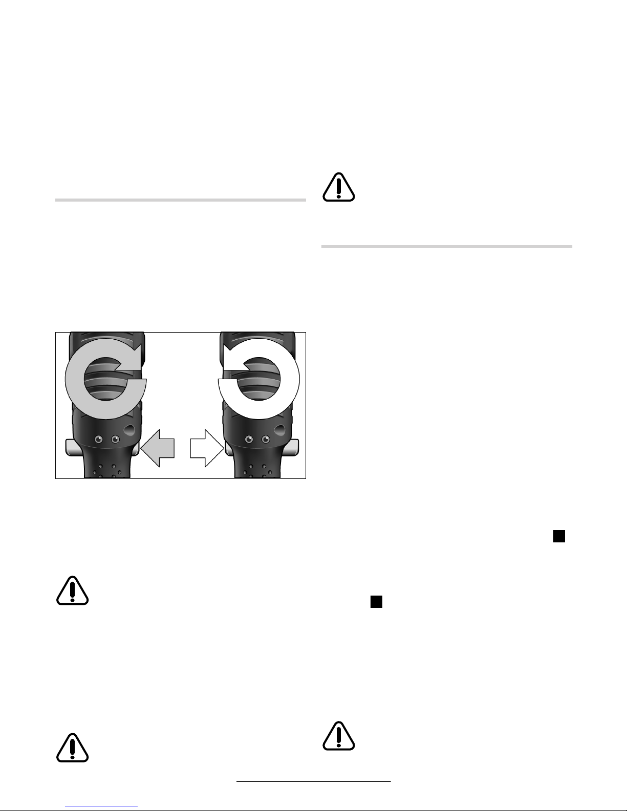
Français–7
3 609 929 879 • (03.02) T
Modèle 0 602 490 639 / … 640
Extraire l’outil 1 hors de la fixation 2, si nécessaire au
moyen d’une pince.
Etrier de suspension
L’étrier de suspension 8 permet d’accrocher l’outillage
à un dispositif de suspension.
Disposer l’étrier de suspension 8 (fourni en tant qu’accessoire) sur l’outillage puis le verrouiller en position
dans les fentes 15.
Contrôler régulièrement l’état de l’étrier de suspension
ainsi que celui du crochet du dispositif de suspension.
Mise en service
Pour mettre l’outillage électroportatif en marche, choisir d’abord un sens de rotation au moyen du commutateur du sens de rotation droite/gauche 14 : l’outilla-
ge électroportatif ne peut être mis en marche qu’une
fois que le commutateur 14 n’est plus sur sa position
centrale (verrouillage d’enclenchement).
Sélection du sens de rotation
Rotation à droite :
Enfoncer le commutateur du sens de rotation droite/gauche 14 à fond vers la gauche (vissage de vis).
Rotation à gauche :
Enfoncer le commutateur du sens de rotation droite/gauche 14 à fond vers la droite (déblocage, dévissage de vis).
N’actionner le commutateur 14 que lorsque l’outillage est parfaitement à l’arrêt.
Activation de la diode d’éclairage de la zone
de travail
Lorsque les conditions d’éclairage sont par ailleurs défavorables, la diode d’éclairage de la zone de travail 21
permet d’éclairer la zone de vissage. Pour activer la
diode 21, enfoncer légèrement l’interrupteur Marche/Arrêt 13. Une pression plus ferme sur l’interrupteur Marche/Arrêt 13 met en marche l’outillage ; la diode 21 continue d’éclairer la zone de travail.
Ne pas regarder directement la diode
d’éclairage de la zone de travail. Risque
d’éblouissement !
Mise en marche/Arrêt
Cet outillage est doté d’un dispositif de débrayage
asservi au couple qui réagit dans la plage indiquée. Ce
dispositif interrompt la rotation dès que le couple présélectionné a été atteint.
Mise en marche :
Enfoncer à fond l’interrupteur Marche/Arrêt 13.
L’outillage électroportatif s’arrête automatiquement dès que le couple présélectionné est atteint.
Arrêt :
Relâcher l’interrupteur Marche/Arrêt 13.
Si l’interrupteur Marche/Arrêt 13 est relâché
trop tôt, le couple présélectionné n’est pas atteint.
Instructions d’utilisation
Extraire la batterie avant de procéder à des réglages sur l’outillage électroportatif, changer
d’accessoire ou bien entreposer l’outillage électroportatif. Cette précaution permet de prévenir tou-
te mise en marche intempestive de l’outillage électroportatif.
Extraction de la batterie
La batterie 11 est logée dans la poignée de l’appareil.
Appuyer des deux côtés sur les touches de déver-
rouillage 12 et extraire la batterie 11 par le bas hors de
la poignée. Ne pas forcer.
Réglage du couple de serrage
Le couple dépend de la tension du ressort du dispositif
de débrayage. Ce dernier se déclenche lors des rotations à gauche comme à droite, à chaque fois que le
couple présélectionné est atteint.
Pour procéder au réglage individuel du couple de coupure, utiliser uniquement l’outil de réglage 23 (Fig. ).
Repousser complètement le curseur 7 de l’outillage
électroportatif. Disposer la clé mâle coudée six pans
24 dans l’outil 1. La faire tourner jusqu’à voir apparaître un petit évidement dans le dispositif d’accouplement (Fig. ). Engager et tourner l’outil de réglage 23
dans cette dépression.
Pour augmenter le couple de serrage, tourner dans le
sens des aiguilles d’une montre. Pour diminuer le couple de serrage, tourner dans le sens inverse.
Remarque : le réglage nécessaire dépend du type de
vissage. Il se détermine très facilement par des essais
pratiques. Contrôler le couple atteint dans l’essai pratique à l’aide d’une clé dynamométrique.
Régler le couple uniquement à l’intérieur
de la plage de valeurs indiquée, au risque, sinon, que le dispositif de débrayage
n’entre pas en action.
14
B
C
Page 28
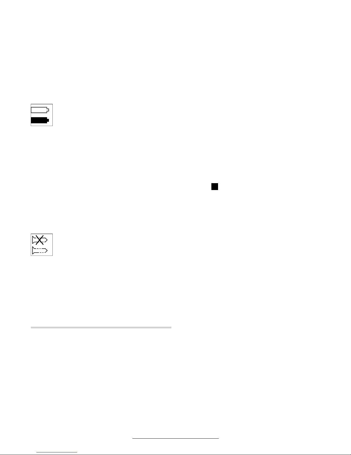
Français–8
3 609 929 879 • (03.02) T
Marquage du réglage du couple
Afin d’identifier de manière individuelle le réglage du
couple auquel il a été procédé, il est possible d’échanger la bague de marquage 18 contre une bague identique mais d’une autre couleur. Décoller la bague de
marquage 18 au moyen d’un embout de tournevis,
d’une spatule, etc.
Utiliser toujours l’outillage électroportatif avec une bague de marquage. En cas d’absence de la bague, le
carter de l’outillage n’est pas fermé.
Diodes (DEL) témoin
Témoin (DEL) d’état de charge de la
batterie
Lorsque la recharge de la batterie 11 s’avère
nécessaire, le témoin d’état de charge de la
batterie 10 se met à clignoter en vert.
L’outillage électroportatif peut encore effec-
tuer de 6–8 vissages, environ.
Lorsque le témoin (DEL) s’allume en rouge, cela signifie que la capacité encore disponible ne suffit plus pour
un nouveau vissage. L’outillage électroportatif ne peut
plus être mis en marche. Le verrouillage d’enclenchement reste actif jusqu’à ce qu’une batterie chargée
soit mise en place.
Une durée d’utilisation de l’outillage sensiblement raccourcie après chaque recharge trahit le fait que la batterie doit bientôt être remplacée. Se débarrasser des
batteries usagées conformément aux dispositions
légales/nationales.
Témoin de vissage
Lorsque le couple présélectionné est atteint,
le dispositif de débrayage intervient. Le té-
moin (DEL) 9 s’allume en vert.
Lorsque le couple présélectionné n’est pas atteint, le
témoin de vissage 9 s’allume en rouge et un signal
acoustique retentit. Le vissage doit être effectué encore une fois.
Protection anti-répétition
Lorsque le dispositif de débrayage est intervenu, cela
provoque également l’arrêt du moteur. La remise en
marche du moteur n’est possible qu’après une pause
de 0,7 seconde. Cela évite de resserrer de manière intempestive des assemblages par vis déjà correctement serrés.
Autres positions de la tête angulaire
La tête angulaire 3 dispose d’un total de huit positions
différentes sur l’outillage.
Immobiliser l’outillage en engageant la clé à fourche 6
sur les méplats 5 ménagés sur la tête angulaire.
Ne jamais immobiliser l’outillage au niveau de la
cartérisation !
Débloquer le contre-écrou en engageant la clé à fourche 4 sur ses méplats 17. Faire effectuer à la tête angulaire 3 une ou plusieurs rotations de 45° jusqu’à atteindre la position désirée. Rebloquer ensuite le
contre-écrou en appliquant la clé à fourche 4 sur les
méplats 17 du contre-écrou. Assurer l’immobilité de la
tête angulaire en la maintenant au moyen de la clé à
fourche 6 disposée sur ses méplats.
Réglage de la position de la diode de travail
(cf. figure )
Appuyer sur la bague de marquage 18 au moyen
d’une fine empreinte de tournevis ou d’un quelconque
objet approprié. Repousser le circlip 19 au moyen
d’une pince appropriée vers l’arrière, sur la cartérisation.
Les deux moitiés de la cartérisation du support 16 de
la diode de travail 21 peuvent désormais être amenées
dans n’importe quelle position angulaire. Veiller à ne
pas endommager les fils électriques de la diode de travail. Les repousser sans les plier dans l’évidemment
20 prévu à cet effet. Remettre en place la diode 21
dans les deux moitiés de la cartérisation du support de
diode 16. Remettre le circlip 19 et la baque de marquage 18 dans leurs positions respectives initiales.
5 MAINTENANCE ET SERVICE-APRES-VENTE
Maintenance
Extraire la batterie avant de procéder à des réglages sur l’outillage électroportatif, changer
d’accessoire ou bien entreposer l’outillage électroportatif. Cette précaution permet de prévenir tou-
te mise en marche intempestive de l’outillage électroportatif.
Lorsque la batterie n’est pas en usage, la tenir à
l’écart d’objets métalliques, tels que trombones,
pièces de monnaie, clés, clous, vis ou autres petits objets métalliques susceptibles d’établir une
connexion entre les contacts électriques. La con-
nexion entre eux des contacts des batteries peut générer un court-circuit, des étincelles ou un incendie.
Si, malgré tous les soins apportés à la fabrication et au
contrôle de l’appareil, celui-ci devait avoir un défaut, la
réparation ne doit être confiée qu’à un centre de services pour outillage Bosch agréé.
Pour obtenir des informations complémentaires ou
lors de la commande de pièces de rechange, préciser
toujours le numéro de commande à 10 positions qui figure sur la plaquette signalétique de l’outillage.
A
Page 29
Français–9
3 609 929 879 • (03.02) T
Procéder au premier nettoyage des engrenages après
environ 150 heures de fonctionnement. Les suivants
seront ensuite effectués toutes les 300 heures de
fonctionnement. Après chaque nettoyage, les engrenages doivent être graissés avec une graisse spéciale
pour engrenage.
Après environ 100000 vissages, les pièces mobiles de
l’accouplement doivent être graissées avec quelques
gouttes d’huile pour moteur SAE 10/SAE 20. Les pièces coulissantes et roulantes doivent être graissées
avec de la graisse Molykote. Procéder ensuite au contrôle du réglage du dispositif de débrayage.
Lubrification
Lubrifiant :
Graisse spéciale pour
engrenages 225 ml 3 605 430 009
Graisse Molykote
Huile pour moteurs SAE 10 / SAE 20
Ne confier la maintenance et la réparation du
présent outillage électroportatif qu’à des professionnels qualifiés. Cela garantit que la sécurité de
l’outillage électroportatif ne sera pas altérée.
Les centres de services Bosch agréés sont en mesure
d’exécuter ces travaux de maintenance de manière rapide et fiable.
Se débarrasser des produits de nettoyage et des
lubrifiants usagés en respectant l’environnement. Tenir compte de la législation en vigueur.
Accessoires
Bosch propose les chargeurs de batteries suivants :
AL 15 FC 2498
ML 60-4
Les centres de services pour outillages électroportatifs
Bosch agréés ainsi que les revendeurs spécialisés
sont en mesure d’aider l’utilisateur dans le choix du
chargeur le plus approprié.
Les sites internet www.bosch-pt.com et
www.boschproductiontools.com ainsi que votre revendeur spécialisé sont en mesure de fournir toutes
les informations souhaitées sur l’ensemble de la gamme d’accessoires Bosch.
Service
Dans le cadre des dispositions légales/nationales, la
société Robert Bosch GmbH se porte garante de la livraison contractuelle du présent outillage. En cas de
réclamation portant sur cet outillage, prière de prendre
contact avec :
Fax . . . . . . . . . . . . . . . . . . . . . +49 (711) 7 58 24 36
www.boschproductiontools.com
Elimination
Les outillages, comme d’ailleurs leurs accessoires et
emballages, doivent pouvoir suivre chacun une voie
de recyclage appropriée.
Nos pièces plastiques ont ainsi été marquées en vue
d’un recyclage sélectif des différents matériaux.
Ne pas tenter de démonter
la batterie ou de démonter
des éléments qui dépassent au niveau des contacts électriques de la batterie. Cela serait suscep-
tible d’entraîner un incendie ou des blessures. Avant
de se débarrasser de la batterie, protéger les contacts
électriques nus avec un ruban isolant afin de prévenir
les court-circuits.
Batterie au nickelcadmium : Si l’outillage
électroportatif est doté d’une
batterie au nickel-cadmium,
en fin de vie, la batterie doit
être recyclée ou éliminée
dans le respect de l’environnement.
Les batteries défectueuses ou usagées doivent être
recyclées, conformément à la directive 91/157/CEE.
Les batteries et piles qui ne sont plus en état de fonctionner peuvent être remis directement à :
Suisse
Batrec AG
3752 Wimmis BE
Sous réserve de modifications
Page 30

Español–1
3 609 929 879 • (03.02) T
1 INSTRUCCIONES GENERALES DE SEGURIDAD
PARA APARATOS ACCIONADOS POR ACUMULADOR
Lea íntegramente estas instrucciones. En caso de no atenerse
a las instrucciones de seguridad
siguientes ello puede dar lugar a una descarga eléctrica, incendio o lesión seria. El término “herramienta
eléctrica” empleado en las siguientes indicaciones de
aviso se refiere a su aparato eléctrico portátil ya sea
con cable de red o, sin cable, en caso de ser accionado por acumulador.
CONSERVE ESTAS INSTRUCCIONES EN UN LUGAR SEGURO.
Puesto de trabajo
Mantenga limpio y bien iluminado su puesto de
trabajo. El desorden y una iluminación deficiente en
las áreas de trabajo pueden provocar accidentes.
No utilice la herramienta eléctrica en un entorno
con peligro de explosión, en el que se encuentren combustibles líquidos, gases o material en
polvo. Las herramientas eléctricas pueden producir
chispas que pueden llegar a inflamar los materiales en
polvo o los vapores.
Mantenga alejados a los niños y otras personas
de su puesto de trabajo al emplear la herramienta
eléctrica. En caso de que otras personas le distraigan
puede llegar a perder el control sobre el aparato.
Seguridad personal
Esté atento a lo que hace y emplee la herramienta
eléctrica con prudencia. No utilice la herramienta
eléctrica si estuviese cansado, ni tampoco después de haber consumido alcohol, drogas o medicamentos. El no estar atento durante el uso de una
herramienta eléctrica puede provocarle serias lesiones.
Utilice un equipo de protección y en todo caso
unas gafas de protección. El riesgo a lesionarse se
reduce considerablemente si, dependiendo del tipo y
la aplicación de la herramienta eléctrica empleada, se
utiliza un equipo de protección adecuado como una
mascarilla antipolvo, zapatos de seguridad con suela
antirresbaladiza, casco, o protectores auditivos.
Evite una puesta en marcha fortuita de la herramienta eléctrica. Cerciorarse de que el interruptor de conexión/desconexión se encuentre
en la posición de “Desconexión” antes de insertar el acumulador en la herramienta eléctrica. Si
transporta la herramienta eléctrica sujetándola por el
interruptor de conexión/desconexión, o al insertar el
acumulador encontrándose el interruptor de conexión/desconexión en la posición de “Conexión”, ello
puede dar lugar a un accidente.
Retire las herramientas de ajuste o llaves fijas
antes de conectar la herramienta eléctrica. Una
herramienta o llave colocada en una pieza giratoria
puede producir lesiones al ponerse a funcionar.
Sea precavido. Trabaje sobre una base firme y
mantenga el equilibrio en todo momento. Ello le
permitirá controlar mejor la herramienta eléctrica al
presentarse una situación inesperada.
Lleve puesta una vestimenta de trabajo adecuada. No utilice vestimenta amplia ni joyas. Mantenga su pelo, vestimenta y guantes alejados de
las piezas móviles del aparato. La vestimenta suel-
ta, las joyas y el pelo largo pueden ser agarrados por
las piezas en movimiento.
Siempre que sea posible utilizar unos equipos de
aspiración o captación de polvo, asegúrese que
éstos estén montados y que sean utilizados correctamente. El empleo de estos equipos reduce los
riesgos derivados del polvo.
Trato y uso cuidadoso de herramientas
eléctricas
No sobrecargue la herramienta eléctrica. Emplee la herramienta eléctrica adecuada al trabajo
que quiera realizar. Con la herramienta eléctrica co-
rrecta trabajará mejor y más seguro dentro del margen
de potencia indicado.
No use herramientas eléctricas con un interruptor de conexión/desconexión defectuoso. Las he-
rramientas eléctricas que no puedan conectarse o
desconectarse son peligrosas y deben hacerse reparar.
Guarde la herramientas eléctricas fuera del alcance de los niños. No permita que empleen la
herramienta eléctrica aquellas personas que no
estén familiarizadas con su uso o que no hayan
leído estas instrucciones. Las herramientas eléctri-
cas son peligrosas para personas sin experiencia.
Cuide con esmero su herramienta eléctrica.
Controle si funcionan correctamente, sin atascarse, las partes móviles del aparato y si existen
partes rotas o deterioradas que pudieran afectar
al funcionamiento de la herramienta. Haga reparar las piezas defectuosas del aparato antes de
volver a utilizar la herramienta eléctrica. Muchos
de los accidentes son provocados por aparatos con
un mantenimiento deficiente.
Mantenga limpios los útiles. Los útiles cuidados
con esmero se dejan guiar y controlar mejor.
Page 31

Español–2
3 609 929 879 • (03.02) T
Utilice herramientas eléctricas, accesorios, útiles, etc. de acuerdo a estas instrucciones y en la
manera indicada específicamente para este aparato. Considere en ello las condiciones de trabajo y la tarea a realizar. El uso de herramientas eléc-
tricas para trabajos diferentes de aquellos para los que
han sido concebidas puede resultar peligroso.
Servicio
Únicamente haga reparar su herramienta eléctrica por un profesional, empleando exclusivamente piezas de repuesto originales. Solamente así se
mantiene la seguridad de la herramienta eléctrica.
2 INSTRUCCIONES DE SEGURIDAD ESPECÍFICAS
PARA BLOQUES DE ACUMULADORES
No arroje los acumuladores al fuego ni los exponga al calor intenso. Pueden explotar.
En caso de unas condiciones de trabajo o temperatura extremas pueden producirse fugas en
los acumuladores. Evite el contacto con la piel u
ojos al haber manipulado un acumulador con fugas.
El líquido del acumulador es cáustico y puede
causar quemaduras químicas en los tejidos. Si el líquido entra en contacto con la piel, enjuáguela inmediatamente con agua y jabón y luego con jugo de limón o
vinagre. Si el líquido entra en contacto con los ojos,
enjuáguelos con agua durante 10 minutos como mínimo, y acuda inmediatamente a un médico.
Los acumuladores vacíos de la herramienta deberán recargarse solamente con el cargador
previsto. La utilización de un cargador incorrecto
puede provocar un incendio.
Preste atención a aquellos acumuladores cuya
vida útil esté a punto de concluirse. Los acumula-
dores pueden cargarse generalmente entre 1000 y
3000 veces (dependiendo del cargador utilizado). Al
notar una menor potencia o unos tiempos de funcionamiento marcadamente menores entre cada carga,
ello es señal de que hay que cambiar el acumulador.
En caso contrario ello puede provocar un funcionamiento deficiente del aparato o dañar el cargador.
En caso de no precisar el acumulador, guárdelo
separado de objetos metálicos como: clips, monedas, llaves, clavos, tornillos u otros objetos
metálicos que pudieran puentear sus terminales.
Al puentearse los terminales de los acumuladores, ello
puede causar un cortocircuito, salto de chispas, o un
incendio.
Jamás guarde los acumuladores dentro del cargador. La vida útil de los acumuladores y su capaci-
dad de carga es mayor, si se guardan por separado.
No se olvide de cargar completamente un acumulador
antes de su uso si no ha sido utilizado durante mucho
tiempo.
PARA ATORNILLADORAS ACCIONADAS POR ACUMULADORES
Sujete el aparato por la parte aislada de las empuñaduras si existe el peligro de que el aparato
pueda tocar un conductor oculto. Al tocar un con-
ductor bajo tensión quedan sometidas a tensión las
partes metálicas externas del aparato pudiendo sufrir
así por ello una descarga eléctrica.
Utilice unos aparatos de exploración adecuados
para detectar conductores o tuberías ocultas, o
consulte a sus compañías abastecedoras. El con-
tacto con conductores eléctricos puede provocar un
incendio y una sacudida eléctrica. Al dañar una tubería
de gas puede producirse una explosión. La perforación de una tubería de agua pueden causar daños
materiales.
Proteja la herramienta eléctrica de la lluvia o humedad. En caso de penetrar agua en la herramienta
eléctrica aumenta el riesgo a exponerse a una descarga eléctrica.
Desmonte el acumulador del aparato antes de
realizar ajustes en el aparato, al cambiar los accesorios o guardar el aparato. Esta medida de precau-
ción evita la puesta en marcha accidental del aparato.
Al insertar el útil preste atención a que su vástago quede firmemente sujeto en el portaútiles. Si
el vástago del útil no se hubiese introducido suficientemente en el portaútiles, puede que al trabajar éste se
salga completamente de su alojamiento.
Utilice solamente útiles en perfecto estado, sin
desgastar. Los útiles defectuosos son propensos a
romperse pudiendo causar lesiones y daños materiales.
Utilice un dispositivo de sujeción o un tornillo de
banco para fijar la pieza de trabajo. La sujeción de
la pieza de trabajo con la mano o presionándola contra
el cuerpo no le permite manejar el aparato de forma
segura.
Page 32

Español–3
3 609 929 879 • (03.02) T
Esté atento al par de reacción que puede presentarse al enroscar o aflojar un tornillo. Al enroscar o
aflojar tornillos se obtiene en la carcasa del aparato un
par de reacción en sentido opuesto al sentido de trabajo cuya magnitud depende del par de giro ajustado.
Solamente aplique el útil sobre la tuerca/tornillo
con el aparato desconectado. Los útiles en rota-
ción pueden resbalar de la tuerca/tornillo.
Tenga cuidado al enroscar tornillos largos ya
que el útil puede resbalar con cierta facilidad según el tipo de tornillo y la lámina de destornilla-
dor utilizada. En los tornillos largos resulta más difícil
controlar el útil y existe el riesgo a lesionarse al enroscarlos si éste resbala.
Antes de conectar el aparato, preste atención al
sentido de giro ajustado. Si al querer aflojar un tor-
nillo, p.ej., el sentido de giro ajustado correspondiese
al de apriete, ello puede ocasionar un brusco par de
reacción en el aparato.
No conecte el aparato al transportarlo. Un por-
tabrocas en funcionamiento puede lesionarle al agarrarle la ropa o el pelo.
Page 33

Español–4
3 609 929 879 • (03.02) T
SIMBOLOGÍA
Nota importante: algunos de los símbolos siguientes pueden ser importantes en la aplicación de su aparato.
Por ello, intente retener en su memoria los símbolos y su significado. La interpretación correcta de los símbolos
facilita, y hace más seguro, el manejo del aparato.
Símbolo Denominación Significado
V Voltios Tensión eléctrica
A Amperios Intensidad
Ah Amperios-hora Capacidad, cantidad de energía acumulada
Hz Hercios Frecuencia
W Vatios Potencia
Nm Newton-metro Unidad de energía, par de giro
kg Kilogramo Masa, peso
mm Milímetro Longitud
min/s Minutos/segundos Tiempo, intervalo
°C/°F Grados centígrados/Fahrenheit Temperatura
dB Decibelios Unidad del nivel de sonido relativo
Ø Diámetro P.ej. tamaño de brocas, discos de amolar, etc.
min
-1
/n
0
Revoluciones Revoluciones en vacío
…/min Vueltas o movimientos
por minuto
Vueltas, impactos, órbitas, etc., por minuto
0 Posición de desconexión Velocidad cero, par de giro cero
Giro a izquierdas/derechas Sentido de giro
/ ■
Hexágono interior/cuadradillo
externo
Tipo de portaútiles
Flecha Efectuar la acción en sentido de la flecha
Corriente alterna Tipo de intensidad y tensión
Corriente continua Tipo de intensidad y tensión
Corriente alterna o continua Tipo y característica de intensidad y tensión
Clase de protección II Los aparatos de la clase de protección II están
completamente aislados.
Clase de protección I según DIN:
Tierra de protección (conductor
de protección)
Los aparatos de la clase de protección I deben
conectarse a tierra en ciertos casos.
Símbolo de advertencia Informa al usuario sobre el manejo correcto del
aparato o le advierte sobre un posible peligro.
Casa Proteja la herramienta eléctrica de la lluvia o
humedad.
Acumuladores de Níquel Cadmio/Acumuladores de Níquel
Metal Hidruro
Los acumuladores defectuosos o agotados deben
reciclarse y eliminarse ecológicamente.
Page 34

Español–5
3 609 929 879 • (03.02) T
3 DESCRIPCIÓN DE FUNCIONAMIENTO
Despliegue la solapa con la representación del aparato y manténgala abierta
mientras lee estas instrucciones de
manejo.
Utilización reglamentaria
El aparato ha sido proyectado para enroscar y aflojar
tornillos y tuercas del tamaño y con el par indicados.
Información sobre ruido y vibraciones
Medición de ruidos realizada según EN ISO 15 744.
Imprecisión de la medición 3 dB(A).
Medición de las vibraciones según EN 28 662 y EN
ISO 8662.
La presión acústica típica del aparato determinada
con un filtro A corresponde a 70 dB(A).
El nivel de ruido, con la máquina trabajando, podrá sobrepasar circunstancialmente 85 dB(A).
¡Usar protectores auditivos!
La aceleración típica en la mano-brazo es inferior a
2,5 m/s
2
. Imprecisión de la medición K = 1,2 m/s
2
.
Elementos del aparato
La numeración de los elementos del aparato se refiere
a su representación en la solapa.
1
Útil (p.ej. llave de vaso)*
2
Portaútiles
3
Cabezal de atornillar acodado
4
Llave fija (entrecaras 27)
5
Entrecaras en la brida del cabezal de atornillar
6
Llave fija (entrecaras 22)
7
Corredera (ajuste del par de giro)
8
Estribo de suspension
9
LED indicador de atornillado
10
LED indicador de estado de carga del acumulador
11
Bloque acumulador*
12
Tecla de desenclavamiento del bloque acumulador
13
Interruptor de conexión/desconexión
14
Selector del sentido de giro con bloqueador de conexión
15
Ranuras para el estribo de suspensión
16
Soporte del LED
17
Entrecaras de la tuerca tensora
18
Anillo de identificación
19
Anillo elástico
20
Cavidad en la carcasa
21
LED de iluminación
22
Disco de ajuste del par de giro
23
Útil de ajuste
24
Llave macho hexagonal
* Accesorios
Los accesorios ilustrados o descritos pueden no
corresponder al material suministrado de serie con el
aparato.
Características técnicas
Atornilladora angular industrial
accionada por acumulador
1515888
Número de pedido 0 602 490 ...
... 635 ... 636 ... 637 ... 638 ... 643
Par de giro [Nm] 15 15888
Revoluciones en vacío [min
-1
]
250 250 420 420 420
Tensión [V] 9,6 9,6 9,6 9,6 9,6
Dirección de giro
Portaútiles
■
3/8" ■ 3/8" ■ 3/8" ■ 3/8" ■ 1/4"
Material que se adjunta
Bloque acumulador
Cabezal de atornillar acodado
–
●
●
●
–
●
●
●
– ●
Peso (sin accesorios) aprox. [kg] 1,2 1,7 1,2 1,7 1,2
Page 35

Español–6
3 609 929 879 • (03.02) T
4 OPERACIÓN
Antes de la puesta en marcha
La herramienta no se suministra con el acumulador incorporado en el aparato.
Jamás guarde los acumuladores dentro del cargador. La vida útil de los acumuladores y su capaci-
dad de carga es mayor, si se guardan por separado.
No se olvide de cargar completamente un acumulador
antes de su uso si no ha sido utilizado durante mucho
tiempo.
Carga del acumulador
Antes de montarlo, cargar el acumulador con un cargador adecuado. La descripción detallada del proceso de carga se indica en las instrucciones de manejo
del cargador.
El acumulador está equipado con un sensor de temperatura NTC que solamente permite la carga dentro
del margen de temperaturas entre 0 °C (+32 °F) y
45 °C (+113 °F). Con esto se consigue una larga duración del acumulador. Utilizándolo correctamente, el
acumulador puede recargarse hasta 3000 veces.
Un acumulador nuevo o que no haya sido usado durante largo tiempo alcanza su plena potencia después
de aprox. 5 ciclos de carga y descarga.
Para preservar el acumulador, éste no debe recargarse en caso de haberse solicitado brevemente (p.ej.
unos 3 minutos).
Montaje del acumulador
Empuje el selector del sentido de giro 14 a la posición
intermedia, que corresponde a la del bloqueador de
conexión, y coloque el interruptor de conexión/desconexión 13 en la posición “Desconexión”. De esta manera se evita una conexión accidental del aparato.
Introduzca el acumulador cargado 11 desde abajo en
la empuñadura del aparato. Preste atención a que el
acumulador quede orientado en la posición correcta
antes de insertarlo, y presionarlo hasta que enclave de
forma perceptible en la empuñadura.
Montaje del útil
Tipo 0 602 490 635 / … 636 / … 637 / … 638
Presione hacia adentro la espiga en el cuadradillo del
portaútiles 2, p.ej. con un destornillador estrecho, e in-
serte el útil 1 sobre el cuadradillo. Observe que la espiga quede correctamente alojada en el orificio del útil.
Tipo 0 602 490 639 / … 640
Inserte el útil 1 en el hexágono interior del portaútiles 2
hasta enclavarlo de forma perceptible.
Atornilladora angular industrial
accionada por acumulador
86666
Número de pedido 0 602 490 ... ... 644 ... 639 ... 640 ... 641 ... 642
Par de giro [Nm]86666
Revoluciones en vacío [min-1] 420 650 650 650 650
Tensión [V] 9,6 9,6 9,6 9,6 9,6
Dirección de giro
Portaútiles ■ 1/4" 1/4" 1/4" ■ 1/4" ■ 1/4"
Material que se adjunta
Bloque acumulador
Cabezal de atornillar acodado
●
●
–
●
●
●
–
●
●
●
Peso (sin accesorios) aprox. [kg] 1,7 1,2 1,7 1,2 1,7
Bloque acumulador NiCd 9,6 Cabezales de atornillar acodados ■ 1/4" ■ 3/8" 1/4"
Número de pedido 2 607 335 … … 373 Número de pedido 0 607 453 … … 617 … 620 … 618
Número de celdas 8 Peso aprox. [kg] 0,2 0,2 0,2
Tensión de acumulador [V] 9,6
Capacidad [Ah] 1,7
Peso aprox. [kg] 0,4
Page 36

Español–7
3 609 929 879 • (03.02) T
Desmontaje del útil
Tipo 0 602 490 635 / … 636 / … 637 / … 638
Presione hacia adentro la espiga por el orificio del útil
1 y extraiga éste del portaútiles 2.
Tipo 0 602 490 639 / … 640
Tire del útil 1 para desmontarlo del portaútiles 2, si fuese preciso empleando unas tenazas.
Suspensor
El estribo de suspensión 8 permite enganchar el aparato de un suspensor.
Monte sobre el aparato el estribo de suspensión 8 que
se adjunta, alojando sus extremos en ambas ranuras 15.
Controle periódicamente el estado del estribo de suspensión y del gancho perteneciente al suspensor.
Puesta en funcionamiento
Antes de poner en marcha el aparato debe ajustarse
el sentido de giro deseado con el selector del sentido
de giro 14 ya que el aparato no se pone en marcha si
el selector del sentido de giro 14 se encuentra en la
posición intermedia (bloqueador de conexión).
Ajuste del sentido de giro
Giro a derechas: Presione hacia la izquierda hasta el
tope el selector del sentido de giro
14 (enroscar tornillos).
Giro a izquierdas: Presione hacia la derecha hasta el
tope el selector del sentido de giro
14 (aflojar tornillos).
Únicamente accionar el selector del sentido de giro 14 con el aparato detenido.
Conexión del LED de iluminación
El LED de iluminación 21 permite alumbrar el punto de
atornillado al trabajar en lugares con poca luz. El LED
de iluminación 21 se enciende ejerciendo una leve
presión sobre el interruptor de conexión/desconexión
13. Al presionar con mayor fuerza el interruptor de conexión/desconexión 13 se conecta el aparato, manteniéndose encendido el LED de iluminación 21.
No mire directamente hacia el LED de iluminación, ya que ello puede deslumbrarle.
Conexión y desconexión
Los aparatos disponen de un mecanismo de desconexión con un par de giro ajustable dentro del margen
indicado. Se activa al alcanzar el par de giro ajustado.
Conexión: Presione a fondo el interruptor de co-
nexión/desconexión 13. El aparato se
desconecta automáticamente al alcanzar el par de giro ajustado.
Desconexión: Suelte el interruptor de conexión/des-
conexión 13.
En caso de soltar antes de tiempo el interruptor de conexión/desconexión 13 no se alcanza el par de giro preajustado.
Indicaciones de trabajo
Desmonte el acumulador del aparato antes de
realizar ajustes en el aparato, al cambiar los accesorios o guardar el aparato. Esta medida de precau-
ción evita la puesta en marcha accidental del aparato.
Desmontaje del acumulador
El acumulador 11 va alojado en la empuñadura de la
máquina.
Presione las teclas de desenclavamiento 12 en ambos
lados y saque hacia abajo el acumulador 11 de la empuñadura. No proceda con brusquedad.
Ajuste del par
El par de giro depende de la tensión previa ajustada en
el resorte del mecanismo de desconexión. El mecanismo de desconexión se activa al alcanzar de par de
giro ajustado independientemente del sentido de giro
del aparato.
Para regular el par de giro emplear solamente el útil de
ajuste 23 suministrado (fig. ).
Abra completamente la corredera 7 del aparato. Introduzca en el útil 1 la llave macho hexagonal 24, y gírela
lentamente hasta que quede visible el rebaje que lleva
el acoplamiento (fig. ) en la abertura de la carcasa.
Insertar el útil de ajuste 23 en este rebaje y girar útil de
ajuste 23.
Al girarse en el sentido de las agujas del reloj se incrementa el par de giro, y se reduce girando en sentido
contrario.
Observación: el ajuste requerido depende de las características de la unión atornillada, siendo por ello
aconsejable determinarlo probando. Verificar el resultado obtenido con una llave dinamométrica.
Ajuste el par de giro dentro del margen
indicado, ya que de lo contrario no se alcanzaría a activar el mecanismo de desconexión.
14
B
C
Page 37

Español–8
3 609 929 879 • (03.02) T
Identificación del par de giro ajustado
Para identificar los pares de giro ajustados individualmente puede sustituirse el anillo de identificación 18
por uno de otro color. Desprenda el anillo de identificación 18 con un la punta de un destornillador fino,
una espátula, o cosa similar.
Siempre utilice en el aparato un anillo de identificación,
ya que si no quedaría abierta la carcasa del aparato.
Indicador LED
Indicador del estado de carga del acumulador
Si fuese necesario recargar el acumulador
11 parpadea el LED verde 10. En este caso
puede utilizar el aparato para atornillar toda-
vía unas 6–8 veces aprox.
Al iluminarse el LED indicador rojo se señaliza que la
capacidad del acumulador es insuficiente para efectuar
un atornillado adicional. El aparato no puede conectarse. El bloqueador de conexión se mantiene activo hasta el momento de montar un acumulador cargado.
Si el tiempo de funcionamiento del aparato se redujese considerablemente entre cada recarga, ello es señal de que el acumulador deberá sustituirse en breve.
Elimine los acumuladores agotados de acuerdo a las
prescripciones legales en su país.
Indicador de atornillado
Al alcanzar el par de giro preajustado se ac-
tiva el mecanismo de desconexión. El
LED indicador verde 9 se ilumina.
Si no llegó a alcanzarse el par de giro preajustado se
enciende el LED indicador rojo 9 y se emite una señal
acústica. El atornillado debe repetirse.
Protección contra reapriete
Al haberse activado el mecanismo de desconexión al
atornillar se desconecta el motor. Éste solamente puede conectarse de nuevo transcurrida una pausa de
0,7 segundos. De esta manera se evita reapretar por
descuido un tornillo que ya ha sido apretado.
Ajuste del cabezal de atornillar acodado
El cabezal de atornillar 3 puede montarse en ocho posiciones diferentes.
Introduzca la llave fija 6 en el entrecaras 5 del cabezal
de atornillar.
¡Jamás sujete el aparato aprisionándolo por la
carcasa!
Aplicar la llave fija 4 en el entrecaras 17 y aflojar la tuerca tensora. El cabezal de atornillar 3 puede girarse a la
posición deseada en pasos de 45°; apretar entonces
la tuerca tensora aplicando la llave fija 4 en el entrecaras 17 sujetando para ello el aparato con la llave fija 6.
Ajuste del LED de iluminación (ver figura )
Desprenda el anillo de identificación 18 con un destornillador de hoja delgada, una espátula, o algo similar.
Abra el anillo elástico 19 con unas tenazas de puntas
para anillos, y empújelo hacia atrás sobre la carcasa.
Las dos piezas del soporte 16 que abrazan el LED de
iluminación 21 pueden colocarse ahora en la posición
deseada. Preste atención a no dañar el cable del LED
y alójelo, sin doblarlo, en la cavidad 20 de la carcasa
prevista para tal fin. Sujete nuevamente el LED 21 con
las dos piezas del soporte 16. Coloque el anillo elástico 19 y el anillo de identificación 18 en su posición original.
5 MANTENIMIENTO Y SERVICIO
Mantenimiento
Desmonte el acumulador del aparato antes de
realizar ajustes en el aparato, al cambiar los accesorios o guardar el aparato. Esta medida de pre-
caución evita la puesta en marcha accidental del aparato.
En caso de no precisar el acumulador, guárdelo
separado de objetos metálicos como: clips, monedas, llaves, clavos, tornillos u otros objetos
metálicos que pudieran puentear sus terminales.
Al puentearse los terminales de los acumuladores, ello
puede causar un cortocircuito, salto de chispas, o un
incendio.
Si a pesar del cuidadoso proceso de fabricación y
control la máquina sufriera un fallo, la reparación deberá encargarse a un punto de Servicio Técnico autorizado para herramientas eléctricas Bosch.
Para cualquier consulta o al solicitar piezas de repuesto indicar el nº de pedido de 10 cifras que figura en la
placa de características del aparato.
Después de las primeras 150 horas de servicio,
aprox., deberá limpiarse el engranaje, y a continuación, cada 300 horas de servicio. Después de cada
limpieza el engranaje deberá lubricarse con grasa especial para engranajes.
Las partes móviles del embrague deberán lubricarse
aprox. cada 100000 atornillados con unas gotas de
aceite para motores SAE 10/SAE 20. La piezas deslizantes y rodantes deberán lubricarse con grasa Molykote. Verificar después el ajuste del embrague.
A
Page 38

Español–9
3 609 929 879 • (03.02) T
Lubricación
Lubricante:
Grasa especial para engranajes 225 ml
3 605 430 009
Grasa Molykote
Aceite para motores SAE 10 / SAE 20
Solamente haga realizar los trabajos de mantenimiento y reparación por un profesional. Con ello
se garantiza la seguridad del aparato.
Un taller de servicio Bosch ejecuta estos trabajos de
manera rápida y fiable.
Eliminar lubricantes y agentes limpiadores respetando el medio ambiente. Observar las prescripciones legales.
Accesorios
Bosch ofrece los siguientes cargadores para los acumuladores:
AL 15 FC 2498
ML 60-4
Cualquier servicio técnico autorizado para herramien-
tas eléctricas Bosch o su comercio especializado habitual le asesorará gustosamente en la selección de un
cargador adecuado.
Una información sobre el programa completo de accesorios especiales la puede obtener Vd. en Internet
bajo www.bosch-pt.com y
www.boschproduction-tools.com,
o bien en su comercio especializado habitual.
Servicio
La Robert Bosch GmbH se responsabiliza del suministro contractual de este aparato de acuerdo a las
disposiciones legales específicas de cada país. En
caso de reclamación diríjase a la siguiente dirección:
Fax . . . . . . . . . . . . . . . . . . . . . +49 (711) 7 58 24 36
www.boschproductiontools.com
Eliminación
El aparato, los accesorios y el embalaje debieran someterse a un proceso de recuperación que respete el
medio ambiente.
Para efectuar un reciclaje selectivo se han identificado
las piezas de plástico.
No intente desensamblar el
acumulador ni retirar partes
sobresalientes en los contactos del acumulador.
Esto podría ser causa de incendio o lesión. Antes de
eliminar un acumulador proteja los contactos descubiertos con cinta aislante para evitar cortocircuitos.
Acumulador de NiquelCadmio: Si su producto uti-
liza acumuladores de Níquel
Cadmio, guarde los acumuladores agotados para su reciclaje o eliminación de forma
ecológica.
Los acumuladores inservibles deben reciclarse según
regulaciòn 91/157/CEE.
Los acumuladores/pilas inservibles pueden entregarse directamente a:
España
Servicio Central de BOSCH
Servilotec, S.L.
Polig. Ind. II, 27
Cabanillas del Campo
✆ . . . . . . . . . . . . . . . . . . . . . . . . + 34 901 11 66 97
www.bosch-pt.com
Reservado el derecho de modificaciones técnicas
Page 39

Português–1
3 609 929 879 • (03.02) T
1 INSTRUÇÕES GERAIS DE SEGURANÇA
PARA APARELHOS COM ACUMULADORES
Leia todas as instruções. O
desrespeito das seguintes ins-
truções de segurança podem
ter como consequência choques eléctricos, riscos de
incêndio ou graves lesões. O termo “Ferramenta eléctrica” utilizado nas instruções de segurança a seguir
refere-se à sua ferramenta eléctrica segurada com as
mãos (com cabo de rede) ou ao aparelho com acumulador (sem fio).
GUARDE BEM ESTA INSTRUÇÃO.
Local de trabalho
Mantenha o seu local de trabalho sempre limpo
e bem iluminado. Desordem e áreas insuficiente-
mente iluminadas no local de trabalho podem levar a
acidentes.
Não trabalhe com a ferramenta eléctrica em áreas com risco de explosão, nas quais se encontrem líquidos, gases ou pós inflamáveis. Ferra-
mentas eléctricas podem soltar faíscas que podem
inflamar pós ou vapores.
Mantenha crianças e pessoas afastadas do seu
local de trabalho, enquanto estiver trabalhando
com a ferramenta eléctrica. É possível que perca o
controle sobre o aparelho se for distraído por outras
pessoas durante o trabalho.
Segurança de pessoas
Trabalhe com atenção e observe exactamente o
que está a fazer e seja sensato ao trabalhar com
a ferramenta eléctrica. Não utilize a ferramenta
eléctrica se estiver cansado ou sob influência de
drogas, álcool ou medicamentos. Um momento
de descuido durante a utilização da ferramenta eléctrica pode levar a graves lesões.
Utilize sempre roupas de protecção e óculos de
protecção. A utilização de roupas de segurança,
como por exemplo máscara de protecção contra pó,
sapatos a prova de deslize, capacetes ou protecções
auriculares, de acordo com o tipo e a aplicação da ferramenta eléctrica, reduz o risco de lesões.
Evite colocar a ferramenta em funcionamento involuntariamente. Assegure-se de que o interruptor de ligar-desligar esteja na posição “Desligado” antes de introduzir o acumulador na
ferramenta eléctrica. Caso tiver o dedo sobre o in-
terruptor de ligar-desligar ao transportar o aparelho,
ou se introduzir o acumulador enquanto o interruptor
de ligar-desligar estiver na posição “Ligado”, poderão
ocorrer acidentes.
Remover ferramentas de ajuste ou chaves de parafusos antes de ligar a ferramenta eléctrica.
Caso se encontrar uma ferramenta ou chave numa
parte em rotação do aparelho, podem ser provocadas
lesões.
Não se sobrestime. Mantenha uma posição segura e mantenha sempre o balanço. Desta forma
poderá controlar a ferramenta eléctrica, mesmo em situações inesperadas.
Use roupas de trabalho apropriadas. Não use
roupas ou jóias largas. Mantenha os cabelos,
roupas e luvas afastados das partes do aparelho
que estejam em movimento. Roupas, jóias e cabe-
los compridos podem ser apanhados por peças em
movimento.
Se for possível montar dispositivos para aspiração e coleta de pó, assegure-se, de que estes
estejam conectados e sejam correctamente
aplicados. Estes dispositivos reduzem riscos devido
a poeira.
Manuseio e utilização correctos das ferramentas eléctricas
Não sobrecarregue a ferramenta eléctrica. Utilize a ferramenta eléctrica apropriada para o seu
trabalho. Com a ferramenta eléctrica apropriada tra-
balha-se melhor e com maior segurança na faixa de
potência indicada.
Não utilize jamais uma ferramenta eléctrica com
um interruptor de ligar-desligar defeituoso. Uma
ferramenta eléctrica que não pode mais ser ligada ou
desligada é perigosa e deve ser reparada.
Guarde ferramentas eléctricas que não estejam
a ser usadas fora do alcance de crianças. Não
permita que pessas que não estejam familiarizadas com a ferramenta eléctrica ou com estas
instruções de serviço utilizem-na. Ferramentas
eléctricas são perigosas quando são utilizadas por
pessoas inexperientes.
Trate a sua ferramenta eléctrica com cuidado.
Verifique se todas as partes móveis funcionam
perfeitamente e não emperram, e se há peças
quebradas ou danificadas que possam influenciar o funcionamento da ferramenta eléctrica. Permita que partes do aparelho danificadas sejam
reparadas antes de recolocar a ferramenta eléctrica em funcionamento. Muitos acidentes tem
como motivo uma insuficiente manutenção do aparelho.
Mantenha limpas as ferramentas de trabalho.
Ferramentas de trabalho cuidadosamente tratadas
podem ser conduzidas e controladas com maior facilidade.
Utilize as ferramentas eléctricas, os acessórios,
as ferramentas de trabalho etc. conforme estas
instruções e da forma que foram determinadas
Page 40

Português–2
3 609 929 879 • (03.02) T
para este modelo especial de aparelho. Considere as condições de trabalho e a tarefa a ser realizada. A ferramenta eléctrica não deve ser utilizada
para outras aplicações do que as destinadas, pois isto
pode levar a situações perigosas.
Serviço
A ferramenta eléctrica só deve ser reparada por
pessoal qualificado e com peças de reposição
originais. Desta forma é assegurada a segurança da
ferramenta eléctrica.
2 INSTRUÇÕES DE SEGURANÇA ESPECÍFICAS
PARA O APARELHO
PARA ACUMULADORES
Acumuladores não devem ser expostos ao fogo
ou altas temperaturas. Há risco de explosão.
É possível que acumuladores apresentem fugas
sob extremas condições de aplicação e de temperatura. Evite que um acumulador entre em
contacto com a pele ou com os olhos. O líquido do
acumulador é ácido e pode causar queimaduras químicas de tecidos orgânico. Caso o líquido entrar em
contacto com a pele, deverá lavá-la imediatamente
com água e sabão e em seguida com suco de limão
ou vinagre. Se o líquido entrar em contacto com os
olhos, lave-os no mínimo durante 10 minutos com
água e dirija-se então imediatamente a um médico.
Se os acumuladores integrados ou introduzíveis
de um aparelho com acumulador estiverem vazios, estes só devem ser recarregados com o carregador previsto para tal. Há risco de incêndio caso
for utilizado um carregador errado.
Observe acumuladores que estejam chegando
ao final da sua vida útil. Acumuladores podem ser
recarregados entre 1000 a 3000-vezes (de acordo
com o carregador). Se puder observar uma reduzida
potência do aparelho ou períodos de funcionamento
nitidamente mais curtos entre os carregamentos, deverá trocar o acumulador. Se isto não for feito, poderão ocorrer erros de funcionamento do acumulador ou
danos no carregador.
Guarde o acumulador afastado de objectos metálicos, como por exemplo grampos, moedas,
chaves, pregos, parafusos ou objectos similares
que possam provocar uma ligação em ponte entre os diversos contactos. Uma ligação metálica
em ponta pode provocar um curto ciruito, faíscas ou
incêndio.
Jamais guardar acumuladores em aparelhos
com acumuladores. Acumuladores duram mais
tempo e podem ser recarregados com maior facilidade, se forem guardados separadamente. Lembre de
recarregar completamente o acumulador se este não
tiver sido utilizado durante longo tempo.
PARA APARAFUSADORES COM ACUMULADORES
Segurar o aparelho pelas superfícies isoladas se
durante o trabalho houver risco de entrar em
contacto com um tubos ou cabos escondidos
em muramentos. Ao entrar em contacto com uma li-
nha sob tensão eléctrica, as partes metálicas sem
protecção do aparelho são electrizadas, o que pode
levar a um choque eléctrico.
Utilizar detectores apropriados, para encontrar
cabos e tubos de alimentação, ou consulte a sua
firma local de abastecimento. O contacto com ca-
bos eléctricos pode levar a incêndios ou choques
eléctricos. A perfuração de um tubo de água provoca
danos materiais.
Mantenha a ferramenta eléctrica afastada de
chuva e humidade. A penetração de água na ferra-
menta eléctrica eleva o risco de um choque eléctrico.
Retirar o acumulador do aparelho antes efectuar
ajustes no mesmo, antes de trocar acessórios
ou de armazenar o aparelho. Esta medida de segu-
rança evita que o aparelho seja colocado involuntariamente em funcionamento.
Ao introduzir a ferramenta de trabalho, deverá
observar que a haste da ferramenta de trabalho
esteja firmemente colocada na admissão da ferramenta eléctrica. Se a haste da ferramenta de tra-
balho não for introduzida na admissão da ferramenta
com profundidade suficiente, é possível que a ferramenta de trabalho escorregue para fora e não possa
mais ser controlada.
Utilize apenas ferramentas de trabalho em perfeito estado e não gastas. Ferramentas de trabalho
defeituosas podem quebrar e levar a lesões e danos
materiais.
Utilizar dispositivos de aperto ou um sargento
para fixar a peça a ser trabalhada. O aparelho não
pode ser operado com segurança se for segurado
com a mão ou pressionado contra o corpo.
Esteja atento a um binário de reacção ao atarraxar ou retirar. De acordo com o ajuste do binário, a
carcaça do aparelho tende a movimentos inesperados no sentido contrário ao atarraxar e desatarraxar
um parafuso.
Page 41

Português–3
3 609 929 879 • (03.02) T
Apenas apoiar a ferramenta de trabalho sobre a
porca/parafuso quando o aparelho estiver desligado. Ferramentas de trabalho em rotação podem
deslizar da porca/parafuso.
Tenha cuidado ao atarraxar um parafuso longo,
há risco de deslize conforme o tipo do parafuso
e do bit de aparafusamento utilizado. Frequente-
mente não há possibilidade de controlar perfeitamente
parafusos compridos, de modo que ao atarraxar poderá deslizar da cabeça e sofrer lesões.
Verificar o sentido de rotação ajustado, antes de
ligar o aparelho. Se por exemplo desejar desatarra-
xar um parafuso e o sentido de rotação tiver sido ajustado de modo que o parafuso seja atarraxado, poderá
ser provocado um forte e repentino movimento descontrolado do aparelho.
Jamais ligar o aparelho durante o transporte.
Uma admissão da ferramenta em em rotação pode
enrolar roupas ou cabelos e provocar lesões.
Page 42

Português–4
3 609 929 879 • (03.02) T
SÍMBOLOS
Nota importante: Alguns dos símbolos a seguir podem ser importantes para a utilização do seu aparelho. Por
favor memorize bem os símbolos e os respectivos significados. A interpretação correcta dos símbolos ajuda a
compreender melhor o aparelho e a utilizá-lo com maior segurança.
Símbolo Nome Significado
V Volt Tensão eléctrica
A Ampére Amperagem eléctrica
Ah Ampére hora Capacidade, quantidade de energia eléctrica
acumulada
Hz Hertz Frequência
W Watt Potência
Nm Newtonmeter Unidade energética, binário
kg Quilograma Massa, peso
mm Milímetro Comprimento
min/s Minutos/segundos Período, duração
°C/°F Grau Celsius/Grau Fahrenheit Temperatura
dB Decibel Medida do relativo volume de som
Ø Diâmetro p.ex. diâmetro do parafuso, diâmetro dos discos
de lixa etc.
min
-1
/n
0
Número de rotação Número de rotação em vazio
…/min Rotações ou movimentos
por minuto
Rotações, cursos, voltas etc. por minuto
0 Posição: Desligado Nenhuma velocidade, nenhum binário
Marcha à esquerda/à direita Sentido de rotação
/ ■
Sextavado interior/quadrado
exterior
Tipo da admissão de ferramenta
Seta Efectuar tarefa no sentido da seta
Corrente alternada Tipo de corrente e de tensão
Corrente contínua Tipo de corrente e de tensão
Corrente alternada ou contínua Tipo de corrente e de tensão
Classe de protecção II Aparelhos da classe de protecção II são
completamente isolados.
Classe de protecção I lt. DIN:
Terra de protecção
(condutor de protecção)
Aparelhos da classe de protecção I devem ser
ligados à terra em alguns casos.
Nota de advertência Instrui o utilizador sobre o manuseio correcto do
aparelho e adverte contra possíveis perigos.
Casa Mantenha a ferramenta eléctrica afastada de
chuva e humidade.
Acumuladores de níquel-cádmio/acumuladores de níquel hidreto de metal
Acumuladores defeituosos ou gastos devem ser
reciclados ou eliminados de forma ecológica.
Page 43

Português–5
3 609 929 879 • (03.02) T
3 DESCRIÇÃO DE FUNÇÃO
Por favor abra a página basculante
com a ilustração do aparelho e deixe
esta página aberta enquanto estiver
lendo a instrução de serviço.
Utilização conforme as disposições
O aparelho é determinado para apertar e soltar parafusos, assim como para apertar e soltar porcas, na faixa de dimensões e de potência indicadas.
Informações sobre ruído e vibrações
Valores de medição de ruídos verificados conforme
EN ISO 15 744. Incerteza de medição 3 dB(A).
Valores de medição para vibração verificados conforme EN 28 662 e EN ISO 8662.
O nível de pressão acústica avaliado A do aparelho é
tipicamente de 70 dB(A). O nível de ruído durante o
trabalho pode exceder 85 dB(A).
Utilize protectores acústicos!
A aceleração da mão e do braço é tipicamente inferior
a 2,5 m/s
2
. Incerteza de medição K = 1,2 m/s
2
.
Elementos do aparelho
A numeração dos elementos do aparelho refere-se à
apresentação do aparelho na aba da capa.
1
Ferramenta de trabalho (p.ex. peça intercalada de
aparafusamento)*
2
Encabadouro
3
Ponta de aparafusamento angular
4
Chave de forqueta (SW 27)
5
Superfície para aplicar a chave na flange da
cabeça angular
6
Chave de forqueta (SW 22)
7
Interruptor de deslize (ajuste do binário)
8
Alça de transporte
9
Indicação LED de aparafusamento
10
Indicação LED da situação de carga do
acumulador
11
Acumulador*
12
Tecla de destravamento do acumulador
13
Interruptor de ligar-desligar
14
Comutação direita-esquerda com bloqueio de
ligação
15
Fendas para o arco para pendurar
16
Suporte LED
17
Superfície da chave na porca de capa
18
Anel de marcação
19
Anel de retenção
20
Cavidade na carcaça
21
LED-luz de trabalho
22
Disco de ajuste para ajustar o binário
23
Ferramenta de ajuste
24
Chave de cavilha sextavada
* Acessórios
Acessórios ilustrados ou descritos não estão totalmente abrangidos no fornecimento.
Dados técnicos do aparelho
Aparafusadora industrial angular com acumulador 15 15888
Número de encomenda 0 602 490 ...
... 635 ... 636 ... 637 ... 638 ... 643
Binário de aperto [Nm] 15 15888
Rotações em vazio [min
-1
]
250 250 420 420 420
Tensão [V] 9,6 9,6 9,6 9,6 9,6
Sentido de rotação
Encabadouro
■
3/8" ■ 3/8" ■ 3/8" ■ 3/8" ■ 1/4"
Volume de fornecimento
Acumulador
Ponta de aparafusamento angular
–
●
●
●
–
●
●
●
– ●
Peso (sem acessórios) aprox. [kg] 1,2 1,7 1,2 1,7 1,2
Page 44

Português–6
3 609 929 879 • (03.02) T
4 FUNCIONAMENTO
Antes da colocação em funcionamento
Observe por favor que o acumulador não se encontre
no aparelho aquando do fornecimento.
Jamais guardar acumuladores em aparelhos
com acumuladores. Acumuladores duram mais
tempo e podem ser recarregados com maior facilidade, se forem guardados separadamente. Lembre de
recarregar completamente o acumulador se este não
tiver sido utilizado durante longo tempo.
Carregar o acumulador
Carregar o acumulador num carregador apropriado
antes de introduzí-lo no aparelho. A descrição exacta
do processo de carregamento encontra-se na instrução de serviço do carregador.
O acumulador está equipado com um controle de
temperatura NTC, que só permite um carregamento
na faixa de temperatura entre 0 °C (+32 °F) e 45 °C
(+113 °F), garantindo, assim, uma longa vida útil do
acumulador. Se for usado correctamente, o acumulador poderá ser recarregado até 3000 vêzes.
Um acumulador novo ou um que não foi utilizado por
muito tempo, apenas alcança a sua plena potência
após aprox. 5 ciclos de carga e descarga.
Para ser poupado, o acumulador não deve ser recarregado após uma breve utilização (p.ex. 3 minutos).
Colocação do acumulador
Colocar a comutação de direita-esquerda 14 na posição central, para activar o bloqueio de ligação e colocar o interruptor de ligar-desligar 13 na posição “Desligado”. Desta forma evita-se que o aparelho seja
ligado involuntariamente.
Introduzir o acumulador carregado 11 no punho do
aparelho pelo lado de baixo. Verifique que o acumulador seja introduzido no sentido correcto e que engate
perceptivelmente no punho.
Introduzir a ferramenta de trabalho
Tipo 0 602 490 635 / … 636 / … 637 / … 638
Pressionar o pino no quadrado da recepção da ferramenta 2 para dentro, p.ex. com auxílio de uma estreita
chave de fenda, e deslocar a ferramenta de trabalho 1
sobre o quadrado. Observe, que o pino engate no entalhe da ferramenta de trabalho.
Tipo 0 602 490 639 / … 640
Introduzir a ferramenta de trabalho 1 no sextavado interior da admissão da ferramenta 2, até engatar sensivelmente.
Aparafusadora industrial angular com acumulador 86666
Número de encomenda 0 602 490 ... ... 644 ... 639 ... 640 ... 641 ... 642
Binário de aperto [Nm]86666
Rotações em vazio [min-1] 420 650 650 650 650
Tensão [V] 9,6 9,6 9,6 9,6 9,6
Sentido de rotação
Encabadouro ■ 1/4" 1/4" 1/4" ■ 1/4" ■ 1/4"
Volume de fornecimento
Acumulador
Ponta de aparafusamento angular
●
●
–
●
●
●
–
●
●
●
Peso (sem acessórios) aprox. [kg] 1,7 1,2 1,7 1,2 1,7
Acumulador NiCd 9,6 Cabeças de aparafusamento
angular
■ 1/4" ■ 3/8" 1/4"
Número de encomenda
2 607 335 … … 373
Número de encomenda
0 607 453 … … 617 … 620 … 618
Número de células 8 Peso aprox. [kg] 0,2 0,2 0,2
Tensão do acumulador [V] 9,6
Capacidade [Ah] 1,7
Peso aprox. [kg] 0,4
Page 45

Português–7
3 609 929 879 • (03.02) T
Remover a ferramenta de trabalho
Tipo 0 602 490 635 / … 636 / … 637 / … 638
Pressionar o pino no entalhe da ferramenta de trabalho 1 para dentro, e puxar a ferramenta de trabalho da
admissão da ferramenta 2.
Tipo 0 602 490 639 / … 640
Puxar a ferramenta de trabalho 1 da admissão da ferramenta 2, se necessário, com auxílio de um alicate.
Dispositivo para pendurar
Com o arco para pendurar 8 é possível fixar o aparelho a um dispositivo para pendurar.
Encaixar o arco para pendurar 8, adquirível como
acessório, no aparelho e permitir que engate nas fendas 15.
Controlar regularmente o estado do arco para pendurar e o gancho no dispositivo para pendurar.
Colocação em funcionamento
Se desejar dar partida no aparelho, deveria primeiramente ajustar o sentido de rotação com o comutador
de sentido direita-esquerda 14, pois o aparelho só começa a funcionar, quando o comutador de direita-esquerda 14 não estiver no centro (bloqueio de ligação).
Ajustar o sentido de rotação
Marcha à direita: Pressionar o comutador direita-
esquerda 14 completamente
para a esquerda (atarraxar parafusos).
Marcha à esquerda: Pressionar o comutador direita-
esquerda 14 completamente
para a direita (atarraxar e desatarraxar parafusos).
Apenas accionar o comutador direitaesquerda 14 com o aparelho parado.
Ligar a luz de trabalho LED
A luz de trabalho 21 possibilita a iluminação do local
de aparafusamento no caso de insuficiente iluminação. A luz de trabalho 21 é ligada através de uma leve
pressão sobre o interruptor de ligar-desligar 13. Pressionando firmemente o interruptor de ligar-desligar 13,
é ligado o aparelho e a luz de trabalho 21 continua a
funcionar.
Não olhe directamente na direcção da luz
de trabalho, pois poderá ser ofuscado!
Ligar e desligar
Os aparelhos possuem um acoplamento de desligamento que depende do binário. Este acoplamento
responde logo que for alcançado o binário ajustado.
Ligar: Pressionar completamente o interruptor de
ligar-desligar 13. O aparelho é automaticamente desligado ao ser alcançado o binário
ajustado.
Desligar: Soltar o interruptor de ligar-desligar 13.
Soltando prematuramente o interruptor de ligar-desligar 13 não é alcançado o binário préajustado.
Instruções para o trabalho
Retirar o acumulador do aparelho antes efectuar
ajustes no mesmo, antes de trocar acessórios
ou de armazenar o aparelho. Esta medida de segu-
rança evita que o aparelho seja colocado involuntariamente em funcionamento.
Retirar o acumulador
O acumulador 11 encontra-se no punho da máquina.
Pressionar em ambos os lados sobre as teclas de
destravamento 12 e retirar o acumulador 11 do punho
puxando para baixo. Não fazer força.
Ajustar o binário
O binário depende da tensão da mola do acoplamento
de desligamento. O acoplamento de desligamento responde logo que for alcançado o binário ajustado, tanto
na marcha à direita, como na marcha à esquerda.
Apenas ajuste o binário individual com as ferramentas
de ajuste 23 fornecidas (Fig. ).
Deslocar o interruptor de deslize 7 completamente
para trás no aparelho. Introduzir a chave de caixa sextavada 24 na ferramenta de trabalho 1 e girar lentamente, até aparecer um pequeno entalhe no acoplamento (Fig. ). Introduzir a ferramenta de ajuste 23
neste entalhe e girar a ferramenta de ajuste 23.
Girando no sentido dos ponteiros do relógio, alcançará
um binário mais alto, girando contra o sentido dos
ponteiros do relógio, alcança um binário mais baixo.
14
B
C
Page 46

Português–8
3 609 929 879 • (03.02) T
Indicação: O ajuste necessário depende do tipo de
aparafusamento e pode de preferência ser averiguado
através de um ensaio prático. Controlar o aparafusamento com uma chave de binário.
Só ajuste o binário dentro da faixa de potência indicada, caso contrário o acoplamento de desligamento não responde
mais.
Marcar o ajuste do binário
Para marcar binários individualmente ajustados é possível trocar o anel de marcação 18 por um anel de
marcação de outra cor. Pressionar o anel de marcação 18 com uma chave de fendas fina, uma espátula
ou objecto semelhante.
Sempre utilize o aparelho com um anel de marcação,
caso contrário a carcaça do aparelho não estará mais
fechada.
Indicação LED
Indicação da situação de carga do acumulador
Logo que for necessário carregar o acumulador 11, pisca a indicação LED 10 verde.
Ainda poderá utilizar o aparelho para aprox.
6–8 aparafusamento.
Se o LED de indicação estiver iluminado em vermelho,
significa que a capacidade não é mais suficiente para
um novo aparafusamento. O aparelho não pode mais
ser ligado. O bloqueio de ligação permanece activa,
até que seja introduzido um acumulador carregado.
Um tempo de funcionamento sensivelmente mais curto do aparelho após cada carregamento do acumulador, indica que este deve ser substituido brevemente.
Elimine os acumuladores gastos conforme as normas
legais vigentes no seu país.
Indicação de aparafusamento
O acoplamento de desligamento responde
logo que for alcançado o binário pré-ajusta-
do. O LED de indicação 9 está iluminado em
verde.
Se o binário pré-ajustado não foi alcançado, ilumina-se
a indicação LED 9 vermelha, e soa um sinal acústico.
O aparafusamento deve ser executado novamente.
Protecção contra repetição
O motor é desligado logo que o acoplamento de aparafusamento responder durante um aparafusamento.
Só é possível ligar novamente após uma pausa de
0,7 segundos. Desta forma é evitado que aparafusamentos já firmes sejam reapertados.
Ajustar a cabeça de aparafusamento angular
É possível ajustar a cabeça de aparafusamento angular
3 no total de oito posições.
Segurar o aparelho com a chave de forqueta 6 pela superfície de chave 5 da flange da cabeça angular.
Jamais fixar o aparelho pelo corpo!
Soltar a porca de capa aplicando a chave de forqueta
4 na superfície para aplicar a chave 17. Ajustar a cabeça de aparafusamento angular 3 por respectivamente
45° até a posição desejada, e reapertar a porca de
capa aplicando a chave de forqueta 4 na superfície
para aplicar a chave 17. Enquanto isto deverá reapertar
fixando com a chave de forqueta 6 na flange angular.
Ajustar a luz de trabalho LED (veja figura )
Pressionar o anel de marcação 18 com uma chave de
fenda de ponta fina, uma espátula ou objecto semelhante. Deslocar o anel de retenção 19 para trás, sobre o corpo da carcaça com uma pinça para anel de
retenção.
Agora é possível colocar as duas metades da carcaça
do suporte LED 16, que envolvem a luz de trabalho
LED 21, na posição desejada. Observar, que o cabo
da luz de trabalho LED não seja danificado e desloque-o sem dobrá-lo, para dentro da prevista cavidade
20 da carcaça. Envolver novamente a luz de trabalho
LED 21 com as duas metades da carcaça do suporte
LED 16. Pressionar o anel de retenção 19 e o anel de
marcação 18 novemante para trás, para a posição inicial.
5 MANUTENÇÃO E SERVIÇO
Manutenção
Retirar o acumulador do aparelho antes efectuar
ajustes no mesmo, antes de trocar acessórios
ou de armazenar o aparelho. Esta medida de segu-
rança evita que o aparelho seja colocado involuntariamente em funcionamento.
Guarde o acumulador afastado de objectos metálicos, como por exemplo grampos, moedas,
chaves, pregos, parafusos ou objectos similares
que possam provocar uma ligação em ponte en-
tre os diversos contactos. Uma ligação metálica
em ponta pode provocar um curto ciruito, faíscas ou
incêndio.
Caso o aparelho venha a apresentar falhas, apesar de
cuidadosos processos de fabricação e de controlo de
qualidade, deve ser reparado em um serviço técnico
autorizado para aparelhos eléctricos Bosch.
No caso de questões e encomenda de peças de reposição deverá indicar o número de encomenda de
10 dígitos conforme o logotipo do aparelho.
A
Page 47

Português–9
3 609 929 879 • (03.02) T
A engrenagem deve ser limpa após aprox. 150 horas
de funcionamento, e em seguida a cada 300 horas de
funcionamento. Após cada limpeza esta deveria ser
lubrificada com graxa especial para engrenagens.
As partes do acoplamento móveis do acoplamento
devem ser lubrificadas após aprox. 100000 aparafusamentos com algumas gotas de óleo de motor
SAE 10/SAE 20 nachzufetten. As partes deslocáveis e
rolantes devem ser lubrificadas com gordura Molykote.
Em seguida lubrifique o ajuste do acoplamento.
Lubrificar
Lubrificante:
Lubrificante especial para
engrenagens 225 ml 3 605 430 009
Massa de molycote
Óleo para motores SAE 10/SAE 20
Só permita que os trabalhos de manutenção e
reparação sejam efectuados por pessoal especializado devidamente qualificado. Desta forma é
assegurada a segurança do aparelho.
Estes trabalhos são efectuados rapida e seguramente
em uma oficina especializada Bosch.
Elimine os lubrificantes e materiais de limpeza
de maneira ecológica. Respeite as directivas oficiais.
Acessórios
A Bosch oferece os seguintes carregadores para os
acumuladores:
AL 15 FC 2498
ML 60-4
A oficina autorizada de serviço pós-venda para ferra-
mentas eléctricas Bosch ou o seu revendedor especializado serão certamente de auxílio na selecção do
carregador apropriado.
O completo programa de acessórios de qualidade encontra-se no internet sob www.bosch-pt.com e
www.boschproductiontools.com ou informe-se junto
ao seu revendedor especializado.
Serviço
A Robert Bosch GmbH se responsabiliza pelo fornecimento desta máquina conforme o contrato, dentro
dos ambitos legais específicos do seu país. No caso
de reclamações em relação à máquina, entre por favor
em contacto com:
Fax . . . . . . . . . . . . . . . . . . . . . +49 (711) 7 58 24 36
www.boschproductiontools.com
Eliminação
Recomenda-se sujeitar o aparelho, os acessórios e a
embalagem a uma reutilização ecológica.
Para efeitos de uma reciclagem específica, as peças
de plástico dispõem de uma respectiva marcação.
Não tente desmontar o acumulador nem remover par-
tes salientes nos contactos do acumulador. Isto
poderia levar a incêndio ou lesões. Proteja os contactos desprotegidos contra curto-circuito com uma fita
adesiva isolante, antes de eliminar o acumulador.
Acumulador de níquelcádmio: Se o seu aparelho
estiver equipado com um
acumulador de níquel-cádmio, este acumulador deverá
ser recolhido, reciclado ou eliminado de forma ecológica.
Acumuladores defeituosos ou gastos devem ser reciclados conforme a directiva 91/157/CEE.
Acumuladores e pilhas gastas podem ser enviadas directamente à:
Portugal
Firma SONALUR
(Sociedade Nacional de Metalurgia, Lda.)
Estrada Nacional Nº3, Km 7
V.Nova da Rainha
2050 Azambuja
Reservado o direito a modificações
Page 48

Italiano–1
3 609 929 879 • (03.02) T
1 INDICAZIONI GENERALI DI SICUREZZA
PER MACCHINE A BATTERIA
Leggere tutte le avvertenze. In
caso di inosservanza delle se-
guenti indicazioni di sicurezza possono verificarsi degli shock elettrici oppure svilupparsi
seri pericoli d’incendio o di incidenti. Il termine «elettroutensile» utilizzato nelle seguenti avvertenze di pericolo si riferisce al Vostra attrezzo elettrico portatile
(con cavo di collegamento elettrico) oppure al Vostro
attrezzo a batteria ricaricabile (con cavo di collegamento elettrico).
CONSERVARE BENE LE PRESENTI AVVERTENZE.
Luogo di lavoro
Assicurarsi sempre un luogo di lavoro pulito e
bene illuminato. Un luogo di lavoro disordinato ed
una zona di operazione non sufficientemente illuminata possono provocare il pericolo di incidenti.
Non lavorare con l’elettroutensile né in ambienti
soggetti al pericolo di esplosione, né in ambienti
in cui si trovano liquidi, gas oppure polveri infiammabili. Gli elettroutensili possono provocare una
scia di scintille in grado accendere la polvere oppure i
vapori.
Quando si utilizza l’elettroutensile, evitare che
bambini ed altre persone possano avvicinarsi
alla zona in cui state lavorando. La presenza di al-
tre persone provoca una distrazione che può portare
a perdere il controllo sulla macchina utilizzata.
Sicurezza di persone
Si raccomanda di stare sempre attenti avendo
cura di concentrarsi sempre sulle proprie azioni
e lavorare con l’elettroutensile operando sempre
con la dovuta ragionevolezza. Non utilizzare
l’elettroutensile quando si è stanchi oppure se ci
si trova sotto l’influenza di narcotici, alcol oppure
medicinali. Un momento di disattenzione mentre si
utilizza l’elettroutensile può comportare il pericolo di
seri incidenti.
Indossare abbigliamento protettivo idoneo e
portare sempre occhiali di protezione. A seconda
del tipo di elettroutensile e dell’uso che se ne fa, è possibile ridurre il rischio di incidenti prendendo appositi
accorgimenti di protezione come portando la maschera di protezione contro la polvere, mettendo scarpe di
sicurezza che non scivolano, caschi oppure portando
una protezione acustica.
Assicurarsi sempre che l’elettroutensile non
possa essere avviato involontariamente. Prima
di inserire la batteria ricaricabile nell’apposito
vano dell’elettroutensile, assicurarsi che l’interruttore di avvio/arresto si trovi sulla posizione
«Off». Trasportando l’elettroutensile tenendo il dito
sull’interruttore di avvio/arresto oppure inserendo la
batteria ricaricabile mentre l’interruttore di avvio/arresto si trova nella posizione «On», si viene a creare un
serio pericolo di incidenti.
Prima di accendere l’elettroutensile, togliervi
ogni utensile d’impostazione oppure chiave. Un
utensile oppure una chiave che si trovi in una parte rotante della macchina può provocare seri incidenti.
Mai sopravvalutare le proprie possibilità di reazione. Prendere sempre una sicura posizione di
lavoro, ed assicurarsi l’equilibrio in qualsiasi momento. In questo modo è possibile poter controllare
meglio l’elettroutensile quando si presentano situazioni inaspettate.
Indossare sempre abbigliamento idoneo. Non indossare vestiti larghi, né portare bracciali e catenine. Tenere i capelli, i vestiti ed i guanti sempre
lontani da parti rotanti della macchina. Vestiti
aperti e larghi, bracciali, catenine e capelli lunghi potrebbero rimanere impigliati in parti rotanti.
In caso fosse previsto il montaggio di dispositivi
di aspirazione della polvere e di raccolta, assicurarsi che gli stessi siano collegati e che vengano
utilizzati correttamente. L’utilizzo di tali dispositivi
contribuisce a ridurre lo svilupparsi di situazioni pericolose provocate dalla presenza di polvere.
Trattamento accurato ed uso corretto degli
elettroutensili
Non sottoporre l’elettroutensile a sovraccarico.
Per il proprio lavoro, utilizzare esclusivamente
l’elettroutensile esplicitamente previsto per il caso. Con un elettroutensile adatto si lavora in modo mi-
gliore e più sicuro nell’ambito della sua potenza di prestazione.
Non utilizzare mai un elettroutensile con un interruttore di avvio/arresto difettoso. Un elettroutensi-
le con l’interruttore rotto è pericoloso e deve essere
aggiustato.
Quando gli elettroutensili non vengono utilizzati,
conservarli al di fuori del raggio di accesso di
bambini. Non permettere di utilizzare l’elettroutensile a persone che non abbiano pratica con lo
stesso oppure che non abbiano letto il presente
manuale. Gli elettroutensili sono macchine pericolose
quando vengono utilizzate da persone non dotate di
sufficiente esperienza.
Curare l’elettroutensile adoperando sempre la
necessaria accuratezza. Accertarsi sempre che
le parti mobili della macchina funzionino perfettamente e che non si blocchino e controllare che
non vi siano componenti rotti oppure danneggiati che potrebbero influenzare il funzionamento
dell’elettroutensile. Prima di mettere nuovamente in funzione l’elettroutensile, provvedere a far
Page 49

Italiano–2
3 609 929 879 • (03.02) T
aggiustare i componenti danneggiati della macchina. Molti incidenti sono provocati dal fatto che le
macchine non vengono sottoposte a sufficienti interventi di manutenzione.
Tenere sempre puliti gli utensili ad innesto. È più
facile lavorare con utensili ad innesto accuratamente
tenuti ed è anche meglio per controllarli.
Utilizzare elettroutensili, accessori, utensili ad innesto ecc. attenendosi alle presenti istruzioni ed
operando sempre in conformità con le indicazioni
prescritte per lo specifico tipo di macchina. Così
facendo, tenere sempre presente le condizioni di
lavoro e le operazione da eseguire. Utilizzando im-
propriamente l’elettroutensile per applicazioni diverse
da quelle esplicitamente previste, vi è il pericolo di creare serie situazioni di pericolo di incidenti.
Assistenza
In caso di necessità di riparazioni dell’elettroutensile, rivolgersi esclusivamente a qualificato
personale specializzato ed accettare esclusivamente pezzi di ricambio originali. In questo modo
si garantisce il livello di sicurezza dell’elettroutensile.
2 ISTRUZIONI DI SICUREZZA SPECIFICHE PER LA MACCHINA
PER PACCHETTI BATTERIE RICARICABILI
Non esporre le batterie ricaricabili né al fuoco, né
ad alte temperature. Vi è concreto pericolo di esplo-
sioni!
In caso di estreme condizioni di impiego oppure di
temperature alte, le batterie ricaricabili possono
perdere la propria ermeticità. Evitare che la pelle
e gli occhi possano entrare in contatto con una
batteria ricaricabile non ermetica. Il liquido conte-
nuto nelle batterie ha proprietà corrosive e può provocare bruciature nel tessuto. Se il liquido entra in contatto
con la pelle, lavare immediatamente la parte interessata
prima utilizzando sapone e acqua e poi succo di limone
oppure aceto. Se il liquido dovesse entrare in contatto
con gli occhi, sciacquarli con acqua almeno per
10 minuti e rivolgersi immediatamente ad un medico.
Quando le batterie ricaricabili di tipo integrate oppure inseribili di una macchina a batteria si scaricano, ricaricarle esclusivamente utilizzando una
stazione di ricarica appositamente prevista per il
caso. Se si utilizza un ricaricatore sbagliato si viene a
creare un serio pericolo d’incendio.
Tenere sotto controllo batterie ricaricabili che si
avvicinano alla fine della propria durata. Le batterie
ricaricabili possono essere ricaricate tipicamente dalle
1000 alle 3000 volte (a seconda della stazione di ricarica). Una volta che si registra un abbassamento della
prestazione della macchina oppure si dovesse riscontrare un’evidente riduzione del tempo di intervallo tra
un’operazione di ricarica e l’altra, vorrà dire che è tempo
di sostituire la batteria ricaricabile. Se in caso si trascurasse di fare tali verifiche, vi è il pericolo di provocare
delle anomalia di funzionamento della macchina a batteria oppure di provocare danni alla stazione di ricarica.
Quando la batteria ricaricabile non serve più, conservarla lontano da oggetti metallici come graffette, monete, chiavi, chiodi, viti oppure oggetti simili
che sarebbero idonei a creare un ponte tra i singoli contatti. Un ponte metallico può provocare un
corto circuito, un’esplosione di scintille oppure lo sviluppo di incendi.
Mai conservare le batterie ricaricabili lasciandole
in una macchina a batterie. Le batterie ricaricabili du-
rano più a lungo e possono essere ricaricate più facilmente se vengono conservate separatamente. Prima di
riutilizzare una batteria ricaricabile dopo un lungo periodo di deposito, non dimenticare di ricaricarla completamente.
PER AVVITATORI A BATTERIA
Tenere la macchina sempre alle superfici di impugnatura isolate quando lavorando con la macchina vi è la possibilità di colpire una linea. In caso
di contatto con una linea sottoposta a tensione, le parti
metalliche non rivestite vengono ad essere sottoposte
ad una tensione che potrebbe provocare uno shock
elettrico.
Al fine di rilevare possibili linee di alimentazione
nascoste, utilizzare adatte apparecchiature di ricerca oppure rivolgersi alla locale società erogatrice. Un contatto con linee elettriche può provocare
lo sviluppo di incendi e di scosse elettriche. Danneggiando linee del gas si può creare il pericolo di esplo-
sioni. Penetrando una tubazione dell’acqua si provocano seri danni materiali.
Evitare che l’elettroutensile possa entrare in
contatto con la pioggia oppure con sostanze liquide. La penetrazione di acqua in un elettroutensile
aumenta il rischio di una scossa di corrente elettrica.
Prima di eseguire operazioni di regolazione sulla
macchina, prima di procedere alla sostituzione
di parti accessorie oppure prima di mettere in
deposito la macchina, estrarre la batteria ricaricabile dalla macchina. Questo accorgimento di si-
curezza ha la funzione di impedire che la macchina
possa essere avviata involontariamente.
Page 50

Italiano–3
3 609 929 879 • (03.02) T
Applicando un utensile ad innesto, assicurarsi
che il gambo dell’utensile ad innesto sia ben fisso nell’attacco utensili. Se il gambo dell’utensile ad
innesto non viene inserito ad una profondità sufficiente
nell’attacco utensili, può capitare che l’utensile ad innesto possa di nuovo uscire e diventare incontrollabile.
Utilizzare esclusivamente utensili in perfetto stato e non usurati. Utensili ad innesto difettosi potreb-
bero per esempio rompersi e provocare gravi incidenti
e danni materiali.
Per bloccare pezzi in lavorazione, utilizzare dispositivi di serraggio oppure una morsa a vite.
Tentando di tenere il pezzo in lavorazione con la semplice mano oppure cercando di tenerlo fermo con il
corpo, non è più possibile operare in modo sicuro con
la macchina.
Avvitando oppure svitando una vite, tenersi sempre pronti a compensare una possibile reazione
di momento torcente. A seconda della regolazione
del momento torcente, avvitando oppure svitando una
vite la carcassa della macchina tende a sviluppare degli spostamenti imprevedibili verso la direzione opposta a quella del senso di rotazione.
Applicare l’utensile ad innesto sul dado/vite
esclusivamente quando la macchina è spenta.
Utensili ad innesto in rotazione possono scivolare via
dal dado/vite.
Avvitando viti lunghe, prestare sempre particolare attenzione perché, a seconda del tipo di vite e
del bit cacciavite utilizzato, vi è il pericolo che
l’inserto possa fuoriuscire dalla testa della vite.
Spesso non è possibile controllare bene le viti lunghe
e, quindi, vi è il pericolo che durante l’operazione di avvitamento possa verificarsi uno scivolamento e provocare un incidente.
Prima di accendere la macchina, accertarsi della
direzione di rotazione registrata. Volendo per
esempio allentare una vite e la direzione di marcia di
rotazione è regolata invece in modo tale che la vite viene avvitata, può capitare che la macchina sviluppi una
reazione forte ed incontrollata.
Mai avviare la macchina mentre viene ancora
trasportata. Un attacco utensili rotante può avvolgere
vestiti oppure capelli che vi rimangono impigliati e provocare seri incidenti.
Page 51

Italiano–4
3 609 929 879 • (03.02) T
SIMBOLI
Avvertenza importante: Alcuni dei simboli che seguono possono essere importanti per l’uso della Vostra mac-
china. È importante imprimersi bene nella mente i simboli ed il rispettivo significato. Un’interpretazione corretta
dei simboli contribuisce ad utilizzare meglio ed in modo più sicuro la macchina.
Simbolo Denominazione Significato
V Volt Tensione elettrica
A Ampere Potenza corrente elettrica
Ah Amperora Autonomia, quantità di energia elettrica accumulata
Hz Hertz Frequenza
W Watt Potenza
Nm Netwon metro Unità di energia, coppia
kg Chilogrammo Massa, peso
mm Millimetro Lunghezza
min/s Minuti/Secondi Periodo di tempo, durata
°C/°F Gradi Celsius/Gradi Fahrenheit Temperatura
dB Decibel Particolare misura del volume acustico relativo
Ø Diametro P.es. diametro della vite, diametro della mola
abrasiva, etc.
min
-1
/n
0
Velocità Velocità in funzionamento a vuoto
…/min Giri oppure movimenti al minuto Giri, colpi, orbite circolari etc. al minuto
0 Posizione: OFF Nessuna velocità, nessuna coppia
Corsa in senso antiorario/orario Senso di rotazione
/ ■
Esagono femmina/
quadro maschio
Tipo dell’attacco utensili
Freccia Esecuzione dell’azione in direzione della freccia
Corrente alternata Tipo di corrente e di tensione
Corrente continua Tipo di corrente e di tensione
Corrente alternata oppure
continua
Tipo di corrente e di tensione
Classe di protezione II Le macchine della classe di protezione II sono
completamente isolati.
Classe di protezione I conf. DIN:
Collegamento messa a terra
(conduttore di protezione)
Le macchine della Classe di protezione I devono in
alcuni casi essere collegati con la massa.
Avvertenza di pericolo Avverte l’operatore della necessità di operare
correttamente con la macchina oppure lo avverte
del pericolo di incidenti
Casa Evitare che l’elettroutensile possa entrare in con-
tatto con la pioggia oppure con sostanze liquide.
Batterie ricaricabili al nichelcadmio/batterie ricaricabili al
nichel-metalidrato
Batterie ricaricabili che siano difettose oppure
usurate devono essere riciclate oppure smaltite in
modo ecologico.
Page 52

Italiano–5
3 609 929 879 • (03.02) T
3 DESCRIZIONE DELLE FUNZIONI
Si prega di aprire la ribaltina su cui si
trova raffigurata schematicamente la
macchina e lasciarla aperta mentre si
legge il manuale delle Istruzioni per
l’uso.
Uso conforme alle norme
La macchina è adatta per avvitare e svitare viti ed anche per avvitare e svitare dadi entro il campo di misurazione e di prestazione indicato.
Informazioni sulla rumorosità e sulla
vibrazione
Valori di misurazione relativi al rumore rilevati conformemente alla norma EN ISO 15 744. Incertezza della
misura 3 dB(A).
Valori di misurazione relativi alla vibrazione rilevati conformemente alla norma EN 28 662 e EN ISO 8662.
La misurazione A del livello di pressione acustica
dell’utensile è di solito di 70 dB(A). Durante le operazioni di lavoro il livello di rumorosità può superare
85 dB(A).
Utilizzare le cuffie di protezione!
La vibrazione su mano-braccio è inferiore a 2,5 m/s
2
.
Incertezza della misura K = 1,2 m/s
2
.
Elementi della macchina
La numerazione degli elementi della macchina si riferisce alla rappresentazione della macchina che si trova
sulla ribaltina.
1
Utensile ad innesto (p.es. adattatore per avvitatore)*
2
Mandrino portautensile
3
Testa vite angolare
4
Chiave a forcella (Misura 27)
5
Superficie chiave alla flangia della testa angolare
6
Chiave a forcella (Misura 22)
7
Interruttore scorrevole (regolazione del momento
torcente)
8
Staffa di sospensione
9
Spia LED avvitamento
10
Spia LED stato di ricarica della batteria ricaricabile
11
Pacchetto di batterie ricaricabili*
12
Tasto di sbloccaggio del pacchetto di batterie
ricaricabili
13
Interruttore di avvio/arresto
14
Commutazione destra/sinistra con blocco di
avviamento
15
Intagli per staffa di sospensione
16
Supporto LED
17
Superficie chiave al dado a risvolto
18
Anello di marcatura
19
Anello elastico
20
Spazio vuoto nel rivestimento portante
21
Luce LED operativa
22
Rotella di regolazione per l’impostazione del
momento di coppia
23
Utensile di regolazione
24
Chiave a brugola
* Accessori
Accessori illustrati o descritti non fanno necessariamente parte del volume di consegna.
Dati tecnici
Avvitatore industriale angolare a batteria 15 15888
Codice di ordinazione 0 602 490 ...
... 635 ... 636 ... 637 ... 638 ... 643
Momento torcente [Nm] 15 15888
Numero di giri a vuoto [min
-1
]
250 250 420 420 420
Tensione [V] 9,6 9,6 9,6 9,6 9,6
Funzionamento reversibile
Mandrino portautensile
■
3/8" ■ 3/8" ■ 3/8" ■ 3/8" ■ 1/4"
Volume di fornitura
Pacchetto di batterie ricaricabili
Testa vite angolare
–
●
●
●
–
●
●
●
– ●
Peso (senza accessori) ca. [kg] 1,2 1,7 1,2 1,7 1,2
Page 53

Italiano–6
3 609 929 879 • (03.02) T
4 UTILIZZO
Prima della messa in servizio
Si prega di tenere presente, che alla consegna la batteria ricaricabile non è inserita nella macchina.
Mai conservare le batterie ricaricabili lasciandole in una macchina a batterie. Le batterie ricaricabili
durano più a lungo e possono essere ricaricate più facilmente se vengono conservate separatamente. Prima di riutilizzare una batteria ricaricabile dopo un lungo
periodo di deposito, non dimenticare di ricaricarla
completamente.
Caricare la batteria
Prima di applicare la batteria ricaricabile nella macchina, provvedere a caricarla utilizzando un’apposita stazione di ricarica. Per una descrizione dettagliata relativa alla procedura da seguire per l’operazione di
ricarica si rimanda alla Istruzioni di utilizzo della stazione di ricarica.
La batteria è equipaggiata con un dispositivo di controllo della temperatura NTC, che permette l’operazione di ricarica soltanto entro valori di temperatura compresi tra 0 °C (+32 °F) e 45 °C (+113 °F). In questo
modo si raggiunge un’elevata durata della batteria.
Eseguendo correttamente le operazioni di ricarica, la
batteria può essere ricaricata fino a 3000 volte.
Una batteria che non sia stata utilizzata per un lungo
periodo di tempo arriva a portare la sua piena prestazione solo dopo ca. 5 cicli di ricarica e scarica.
Per non sottoporre la batteria ricaricabile ad inutile
usura, non ricaricarla in seguito ad utilizzazioni di breve
durata (p.es. 3 minuti).
Inserimento della batteria
Per attivare il blocco di avviamento, spingere la commutazione destra/sinistra 14 sulla posizione centrale e
mettere l’interruttore di avvio/arresto 13 sulla posizione «Off». In questo si evita che la macchina possa essere inserita involontariamente.
Infilare dalla parte inferiore la batteria ricaricata 11
nell’impugnatura della macchina. Attenzione ad inserire correttamente la batteria ricaricabile ed accertarsi
che sia arrivata a fare presa in modo percepibile
nell’impugnatura.
Applicazione dell’utensile ad innesto
Tipo 0 602 490 635 / … 636 / … 637 / … 638
Utilizzando p.es. uno stretto cacciavite, premere il perno all’attacco quadro dell’attacco portautensile 2,
spingerlo verso l’interno e spingere l’utensile ad innesto 1 sopra l’attacco quadro. Accertarsi che il perno
arriva a fare presa nella rientranza dell’utensile ad innesto.
Avvitatore industriale angolare a batteria 86666
Codice di ordinazione 0 602 490 ... ... 644 ... 639 ... 640 ... 641 ... 642
Momento torcente [Nm]86666
Numero di giri a vuoto [min-1] 420 650 650 650 650
Tensione [V] 9,6 9,6 9,6 9,6 9,6
Funzionamento reversibile
Mandrino portautensile ■ 1/4" 1/4" 1/4" ■ 1/4" ■ 1/4"
Volume di fornitura
Pacchetto di batterie ricaricabili
Testa vite angolare
●
●
–
●
●
●
–
●
●
●
Peso (senza accessori) ca. [kg] 1,7 1,2 1,7 1,2 1,7
Pacchetto di batterie al NiCd 9,6 Testa vite angolare ■ 1/4" ■ 3/8" 1/4"
Codice di ordinazione 2 607 335 … … 373 Codice di ordinazione 0 607453 … … 617 … 620 … 618
Quantità degli elementi 8 Peso ca. [kg] 0,2 0,2 0,2
Tensione della batteria [V] 9,6
Capacità [Ah] 1,7
Peso ca. [kg] 0,4
Page 54

Italiano–7
3 609 929 879 • (03.02) T
Tipo 0 602 490 639 / … 640
Inserire l’utensile ad innesto 1 nell’attacco esagono
femmina del portautensili 2, fino a quando arriverà ad
incastrarsi in maniera percepibile.
Rimozione dell’utensile ad innesto
Tipo 0 602 490 635 / … 636 / … 637 / … 638
Premere verso l’interno il perno nella rientranza
dell’utensile ad innesto 1 e tirare l’utensile ad innesto
dall’alloggiamento utensili 2.
Tipo 0 602 490 639 / … 640
Tirare l’utensile ad innesto 1 dall’alloggiamento utensili
2 utilizzando, se necessario, una tenaglia.
Dispositivo di sospensione
Tramite la staffa di sospensione 8 è possibile fissare la
macchina ad uno dei dispositivi di sospensione.
Applicare sulla macchina la staffa di sospensione 8,
accessorio fornito a corredo, e lasciarla innestare in
posizione nell’intaglio 15.
Controllare ad intervalli regolari lo stato della staffa di
sospensione e dei ganci nel dispositivo di sospensione.
Messa in servizio
Per avviare la macchina, impostare prima la direzione
di marcia mediante la Commutazione destra/sinistra
14 perché la macchina si avvia soltanto quando la
Commutazione destra/sinistra 14 non si trova più in
posizione centrale (blocco di avviamento).
Impostazione del senso di rotazione
Rotazione destrorsa:
Premere la Commutazione destra/sinistra 14 verso
sinistra fino alla battuta di arresto (avvitare viti).
Rotazione sinistrorsa:
Premere la Commutazione destra/sinistra 14 verso
destra fino alla battuta di arresto (allentare oppure
svitare completamente le viti).
Azionare la Commutazione destra/sinistra 14 soltanto quando la macchina è
ferma.
Accendere la luce LED operativa
La luce operativa 21 consente di illuminare il punto di
avvitatura in caso di inadeguate condizioni di luce. La
luce operativa 21 si accende pigiando leggermente
l’interruttore di avvio/arresto 13. Premendo più forte
l’interruttore di avvio/arresto 13 si accende la macchina e la luce operativa 21 continua a rimanere accesa.
Non rivolgere mai lo sguardo direttamente nella luce operativa, è possibile restarne abbagliati!
Avviare ed arrestare
Le macchine sono dotate di un momento di coppia che
dipende dal dispositivo di disinserimento e che può
essere regolata nel campo indicato. La frizione scatta
una volta raggiunto il momento torcente impostato.
Avviare: Premere l’interruttore di avvio/arresto 13
fino alla battuta di arresto. La macchina si
disinserisce automaticamente una volta
raggiunto il momento torcente impostato.
Arrestare: Rilasciare l’interruttore di avvio/arresto 13.
Rilasciando anticipatamente la levetta dell’interruttore di avvio/arresto 13 non si raggiunge
più il momento di coppia preimpostato.
Istruzioni per il lavoro
Prima di eseguire operazioni di regolazione sulla
macchina, prima di procedere alla sostituzione
di parti accessorie oppure prima di mettere in
deposito la macchina, estrarre la batteria ricaricabile dalla macchina. Questo accorgimento di si-
curezza ha la funzione di impedire che la macchina
possa essere avviata involontariamente.
Estrazione della batteria ricaricabile
La batteria 11 si trova installata nell’impugnatura della
macchina.
Premere su entrambi i punti del tasto di sbloccaggio
12 ed estrarre la batteria ricaricabile 11 dall’impugnatura tirandola verso il basso. Non forzare.
Impostazione del momento torcente
Il momento di coppia dipende dalla tensione della molla della frizione di stacco. La frizione di stacco si attiva
sia in senso sinistrorso che in senso destrorso una volta raggiunta la coppia precedentemente impostata.
Per impostare un individuale valore di coppia, utilizzare
soltanto l’apposito utensile d’impostazione 23 fornito
a corredo (Fig. ).
Spingere completamente all’indietro l’interruttore scorrevole 7 della macchina. Inserire la chiave a brugola
esagonale 24 nell’utensile ad innesto 1 e ruotarlo lentamente fino a quando nell’apertura del corpo della macchina si intravede una piccola inarcatura nella frizione
(Fig. ). Inserire l’utensile d’impostazione 23 in questa
incurvatura e girare l’utensile d’impostazione 23.
14
B
C
Page 55

Italiano–8
3 609 929 879 • (03.02) T
Ruotando in senso orario si imposta un momento di
coppia maggiore, ruotando in senso antiorario si imposta un momento di coppia minore.
Nota bene: La regolazione necessaria per ogni specifico caso dipende dal tipo di raccordo a vite e deve
dunque essere determinata eseguendo delle prove
pratiche. Controllare l’avvitamento di prova utilizzando
una chiave torsiometrica.
Impostare il valore della coppia esclusivamente nell’ambito della potenza di targa perché altrimenti il dispositivo di disinserimento non può più inserirsi.
Marcatura della regolazione del momento torcente
Per contrassegnare coppie impostate individualmente
è possibile sostituire l’anello di marcatura 18 con un
anello di marcatura di colore diverso. Premure l’anello
di marcatura 18 utilizzando una sottile lama di cacciavite, una spatola o qualcosa di simile.
Utilizzare la macchina sempre con un anello di marcatura perché, in caso contrario, il corpo della macchina
non sarebbe più chiusa.
Spia LED
Spia dello stato di ricarica della batteria
ricaricabile
Una volta che diventa necessario ricaricare la
batteria 11, inizia a lampeggiare la spia LED
10 verde. La macchina può essere utilizzata
ancora per ca. 6–8 operazioni di avvitatura.
Quando la spia LED è rossa, significa che l’autonomia
non è più sufficiente per eseguire una nuova avvitatura. La macchina non può più essere messa in funzione. Il blocco di avviamento resta attivo fino a quando
non sarà stata inserita una batteria carica.
Una sensibile riduzione della durata del funzionamento
della macchina dopo ogni operazione di ricarica sta ad
indicare che la batteria ricaricabile dovrà essere sostituita. Smaltire le batterie usurate operando secondo le
specifiche disposizioni vigenti nel rispettivo Paese.
Indicatore avvitamento
Una volta raggiunta la coppia preimpostata,
il dispositivo di disinserimento si attiva. La
spia LED 9 è accesa ed è verde.
In caso di mancato raggiungimento della coppia preimpostata, si accende la spia LED 9 rossa e viene
emesso un segnale acustico. L’operazione di avviamento deve essere eseguita una seconda volta.
Dispositivo antiripetizione
Se durante un’operazione di avvitamento è stato attivato il dispositivo di disinserimento, il motore si spegne. Il motore può essere di nuovo acceso solo dopo
0,7 secondi. In questo modo è possibile evitare di avvitare involontariamente raccordi che siano già avvitati
a fondo.
Regolazione della testa vite angolare
È possibile regolare la testa vite angolare 3 in otto posizioni totali.
Bloccare la macchina applicando la chiave fissa 6 sulla
superficie chiave 5 della flangia della testa angolare.
Non bloccare mai la macchina facendo presa sul
rivestimento portante!
Applicando la chiave fissa 4 alla superficie chiave 17
allentare il dado per raccordi. Regolare la testa vite angolare 3 rispettivamente di 45° nella posizione che si
desidera ed avvitare di nuovo forte il dado a risvolto
operando con la chiave fissa 4 sulla superficie chiave
17. Così facendo, fare pressione contraria con la chiave fissa 6 alla flangia angolare.
Regolazione della luce LED operativa
(vedi figura )
Premere l’anello di marcatura 18 utilizzando una sottile
lama di cacciavite, una spatola o qualcosa di simile.
Utilizzando una pinza per anello elastico, spingere
all’indietro l’anello elastico 19 sul rivestimento portante.
Le due metà del guscio del supporto LED 16, che
comprendono la luce LED operativa 21, possono
quindi ora essere messe nella posizione che si desidera. Attenzione a non danneggiare il cavo alla luce LED
operativa e spingerlo senza piegarlo nell’apposita cavità 20 del rivestimento portante (a guscio). Racchiudere di nuovo la luce LED operativa 21 con i due rivestimenti a guscio del supporto LED 16. Premere di
nuovo indietro alla posizione originale l’anello elastico
19 e l’anello di marcatura 18.
5 MANUTENZIONE ED ASSISTENZA
Manutenzione
Prima di eseguire operazioni di regolazione sulla
macchina, prima di procedere alla sostituzione
di parti accessorie oppure prima di mettere in
deposito la macchina, estrarre la batteria ricaricabile dalla macchina. Questo accorgimento di si-
curezza ha la funzione di impedire che la macchina
possa essere avviata involontariamente.
Quando la batteria ricaricabile non serve più,
conservarla lontano da oggetti metallici come
graffette, monete, chiavi, chiodi, viti oppure oggetti simili che sarebbero idonei a creare un ponte tra i singoli contatti. Un ponte metallico può pro-
vocare un corto circuito, un’esplosione di scintille
oppure lo sviluppo di incendi.
A
Page 56

Italiano–9
3 609 929 879 • (03.02) T
Se nonostante gli accurati procedimenti di produzione
e di controllo la macchina dovesse guastarsi, la riparazione va fatta effettuare da un punto di assistenza autorizzato per gli elettroutensili Bosch.
In caso di richieste o di ordinazione di pezzi di ricambio, comunicare sempre il codice di ordinazione a 10
cifre dell’elettroutensile riportato sulla targhetta di fabbricazione della macchina.
Dopo ca. 150 ore di funzionamento sarà necessario
pulire per la prima volta gli ingranaggi. In seguito, ogni
300 ore di funzionamento. Dopo ogni operazione di
pulizia si dovrebbe provvedere all’applicazione di lubrificante speciale per la trasmissione.
Le parti mobili della frizione devono essere di nuovo lubrificate rispettivamente ogni ca. 100000 operazioni di
avvitatura applicando alcune gocce di olio per motori
SAE 10/SAE 20. Le parti scorrevoli e ruotanti devono
essere lubrificate con grasso Molykote. Controllare in
seguito l’impostazione della frizione.
Lubrificazione
Lubrificante:
Lubrificante speciale per
trasmissione 225 ml 3 605 430 009
Lubrificante Molykote
Olio per motori SAE 10 / SAE 20
Gli interventi di manutenzione e di riparazione
possono essere eseguiti esclusivamente da qualificato personale specializzato. In questo modo si
garantisce il livello di sicurezza della macchina.
Questo tipo di lavoro viene eseguito in maniera veloce
ed affidabile da ogni Centro di assistenza Clienti
Bosch.
Smaltire lubrificanti e detergenti rispettando
l’ambiente. Rispettare le prescrizioni legislative in
merito.
Accessori
Bosch propone le seguenti stazioni di ricarica per
batterie:
AL 15 FC 2498
ML 60-4
Per poter scegliere un’adatta stazione di ricarica è
possibile rivolgersi ad un Centro per il Servizio Clienti
elettroutensili Bosch autorizzato oppure al proprio Rivenditore di fiducia.
Visitando i siti www.bosch-pt.com e
www.boschproductiontools.com,
oppure rivolgendoVi al Vostro rivenditore di fiducia è
possibile informarsi sulla completa gamma dei prodotti
di accessori di qualità.
Servizio
La Robert Bosch GmbH risponde per la fornitura di
questa macchina come da contratto e conformemente alle specifiche prescrizioni legali vigenti nei rispettivi
Paesi. In caso di anomalia di funzionamento della
macchina, si prega di rivolgersi presso:
Fax . . . . . . . . . . . . . . . . . . . . . +49 (711) 7 58 24 36
www.boschproductiontools.com
Smaltimento
Macchina, accessori ed imballaggio dovrebbero essere inviati ad una riutilizzazione ecologica.
I componenti in plastica sono contrassegnati per il riciclaggio selezionato.
Non tentare di smontare la batteria ricaricabile, né cercare di
rimuovere parti sporgenti dai contatti delle batterie ricaricabili. Ciò potrebbe sviluppare incendi op-
pure provocare incidenti. Prima di smaltire una batteria
ricaricabile, per evitare un corto circuito, proteggere i
contatti aperti applicandovi del nastro isolante.
Batteria ricaricabile al nichel-cadmio: In caso di
macchine dotate di batteria
ricaricabile al nichel-cadmio,
una volta usurata, sarà necessario mettere da parte la
batteria per poterla riciclare
oppure smaltire in conformità
con le vigenti procedure ecologiche.
Le batterie difettose devono essere riciclate conformemente alla direttiva 91/157/CEE.
Batterie ricaricabili/batterie non ricaricabili diventate inservibili possono essere consegnate direttamente
presso:
Italia
Ecoelit
Corso Sempione 15/A
20 145 Milanos
✆ . . . . . . . . . . . . . . . . . . . . . . . . . . . . . 02/34 71 60
Fax . . . . . . . . . . . . . . . . . . . . . . . . . . . 02/331 90 76
ECOELIT@TISCALINET.IT
Svizzera
Batrec AG
3752 Wimmis BE
Con riserva di modifiche
Page 57

Nederlands–1
3 609 929 879 • (03.02) T
1 ALGEMENE VEILIGHEIDSVOORSCHRIFTEN
VOOR ACCUGEREEDSCHAP
Lees alle voorschriften. Wanneer de volgende veiligheids-
voorschriften niet in acht worden genomen, kunnen een elektrische schok,
brandgevaar of ernstige verwondingen het gevolg zijn.
Het in de volgende waarschuwingen gebruikte begrip
„elektrisch gereedschap” heeft betrekking op met de
hand vastgehouden elektrisch gereedschap (met netsnoer) en accugereedschap (snoerloos).
BEWAAR DEZE VOORSCHRIFTEN GOED.
Werkomgeving
Houd uw werkomgeving schoon en goed verlicht. Een rommelige of onverlichte werkomgeving kan
tot ongevallen leiden.
Werk met het elektrische gereedschap niet in
een explosiegevaarlijke omgeving waarin zich
brandbare vloeistoffen, gassen of stof bevinden.
Elektrische gereedschappen kunnen vonken veroorzaken die het stof of de dampen tot ontsteking kunnen
brengen.
Houd kinderen en andere personen uit uw werkomgeving wanneer u het elektrische gereedschap gebruikt. Wanneer u wordt afgeleid door an-
dere personen, kunt u de controle over het
gereedschap verliezen.
Veiligheid van personen
Wees aandachtig, let op wat u doet en ga met
verstand te werk bij het gebruik van het elektrische gereedschap. Gebruik het elektrische gereedschap niet wanneer u moe bent of onder invloed staat van drugs, alcohol of medicijnen. Een
moment van onoplettendheid bij het gebruik van het
elektrische gereedschap kan tot ernstige verwondingen leiden.
Draag altijd een veiligheidsbril en beschermende
kleding. Het dragen van beschermende uitrusting als
een stofmasker, slipvaste werkschoenen, helm of gehoorbescherming, afhankelijk van de aard en het gebruik van het elektrische gereedschap, vermindert de
kans op verwondingen.
Voorkom per ongeluk inschakelen van het elektrische gereedschap. Controleer dat de aan/uitschakelaar in de stand „Uit” staat voordat u de
accu in het elektrische gereedschap steekt. Wan-
neer u bij het dragen van het elektrische gereedschap
de vinger aan de aan/uit-schakelaar heeft of de accu
plaatst terwijl de aan/uit-schakelaar in de stand „Aan”
staat, kan dit tot ongevallen leiden.
Verwijder instelgereedschappen of schroefsleutels voordat u het elektrische gereedschap inschakelt. Een instelgereedschap of sleutel in een
draaiend deel van het elektrische gereedschap kan tot
verwondingen leiden.
Overschat uzelf niet. Zorg ervoor dat u stevig
staat en steeds in evenwicht blijft. Daardoor
kunt u het elektrische gereedschap in onverwachte situaties beter onder controle houden.
Draag geschikte werkkleding. Draag geen loshangende kleding of sieraden. Houd haren, kleding en handschoenen uit de buurt van bewegende delen van het gereedschap. Loshangende
kleding, sieraden en lange haren kunnen door bewegende delen worden meegenomen.
Wanneer stofafzuigings- of stofopvangvoorzieningen gemonteerd kunnen worden, dient u
zich ervan te verzekeren dat deze zijn aangesloten en juist worden gebruikt. Het gebruik van
deze voorzieningen beperkt het gevaar door stof.
Zorgvuldige omgang met en zorgvuldig gebruik van elektrische gereedschappen
Overbelast het elektrische gereedschap niet.
Gebruik voor uw werkzaamheden het daarvoor
bestemde elektrische gereedschap. Met het
passende elektrische gereedschap werkt u beter en
veiliger binnen het aangegeven capaciteitsbereik.
Gebruik geen elektrisch gereedschap waarvan
de aan/uit-schakelaar defect is. Elektrisch ge-
reedschap dat niet meer kan worden in- of uitgeschakeld, is gevaarlijk en moet worden gerepareerd.
Bewaar niet-gebruikte elektrische gereedschappen buiten bereik van kinderen. Laat het
elektrische gereedschap niet gebruiken door
personen die er niet mee vertrouwd zijn en
deze gebruiksaanwijzing niet gelezen hebben.
Elektrische gereedschappen zijn gevaarlijk wanneer
deze door onervaren personen worden gebruikt.
Verzorg het elektrische gereedschap zorgvuldig. Controleer of bewegende delen van het gereedschap correct functioneren en niet vastklemmen en of onderdelen gebroken of
beschadigd zijn die de werking van het elektrische gereedschap kunnen beïnvloeden. Laat
beschadigde delen van het gereedschap repareren voordat u het elektrische gereedschap
weer in gebruik neemt. Veel ongevallen hebben
hun oorzaak in slecht onderhouden gereedschappen.
Houd de inzetgereedschappen schoon. Zorgvul-
dig onderhouden inzetgereedschappen kunnen gemakkelijker worden gebruikt en zijn beter onder controle te houden.
Page 58

Nederlands–2
3 609 929 879 • (03.02) T
Gebruik elektrische gereedschappen, toebehoren, inzetgereedschappen en dergelijke volgens
deze voorschriften en zoals voor dit speciale gereedschaptype voorgeschreven. Let daarbij op
de arbeidsomstandigheden en de uit te voeren
werkzaamheden. Het gebruik van het elektrische ge-
reedschap voor andere dan de voorziene toepassingen kan tot gevaarlijke situaties leiden.
Service
Laat het elektrische gereedschap alleen repareren door gekwalificeerd, vakkundig personeel en alleen met originele vervangingsonderdelen. Daarmee wordt gewaarborgd dat de veiligheid
van het elektrische gereedschap in stand blijft.
2 GEREEDSCHAPSPECIFIEKE VEILIGHEIDSVOORSCHRIFTEN
VOOR ACCUPACKS
Stel accu’s niet bloot aan vuur of hoge temperaturen. Er bestaat explosiegevaar.
Onder extreme gebruiks- en temperatuuromstandigheden kunnen accu’s gaan lekken.
Voorkom contact met huid of ogen bij een lekkende accu. De accuvloeistof is bijtend en kan che-
mische verbrandingen van huid- of oogweefsel veroorzaken. Was de huid onmiddellijk met water en zeep en
vervolgens met citroensap of azijn wanneer de vloeistof in contact met de huid komt. Spoel minstens 10
minuten lang met water en raadpleeg onmiddellijk een
arts wanneer de vloeistof in de ogen komt.
Laad de accu’s alleen op met een daarvoor bedoeld oplaadapparaat wanneer de geïntegreerde of aangebrachte accu’s van een accugereedschap leeg zijn. Bij gebruik van een verkeerd
oplaadapparaat bestaat brandgevaar.
Let goed op bij accu’s die het einde van hun levensduur bijna bereikt hebben. Accu’s kunnen
gewoonlijk 1000 tot 3000 keer worden opgeladen, afhankelijk van het oplaadapparaat. Wanneer u merkt
dat de capaciteit van het gereedschap vermindert of
de gebruikstijd tussen het opladen duidelijk korter
wordt, is het tijd om de accu te vervangen. Wanneer
de accu niet wordt vervangen, kunnen storingen aan
het accugereedschap of beschadigingen van het oplaadapparaat optreden.
Bewaar een niet-gebruikte accu uit de buurt
van metalen voorwerpen die de contacten kunnen overbruggen, zoals paperclips, munten,
sleutels, spijkers, schroeven en dergelijke. Een
metaaloverbrugging kan kortsluiting, vonken of vuur
veroorzaken.
Bewaar accu’s nooit in het accugereedschap.
Accu’s blijven langer goed en kunnen beter worden
opgeladen wanneer deze apart worden bewaard.
Laad een accu na langdurig bewaren voor het gebruik
altijd volledig op.
VOOR ACCUSCHROEVENDRAAIERS
Houd het gereedschap aan de geïsoleerde handvaten vast wanneer u tijdens de werkzaamheden
met het gereedschap een verborgen leiding kunt
raken. Bij contact met een onder spanning staande
leiding komen blootliggende metalen delen van het gereedschap onder spanning te staan, hetgeen tot een
elektrische schok kan leiden.
Gebruik een geschikt detectieapparaat om verborgen stroom-, gas- of waterleidingen op te
sporen of raadpleeg het plaatselijke energie- of
waterleidingbedrijf. Contact met elektrische leidin-
gen kan tot brand of een elektrische schok leiden. Beschadiging van een gasleiding kan tot een explosie leiden. Breuk van een waterleiding veroorzaakt materiële
schade.
Houd het elektrische gereedschap uit de buurt
van regen en vocht. Het binnendringen van water in
het elektrische gereedschap vergroot de kans op een
elektrische schok.
Verwijder de accu uit het gereedschap voordat u
het gereedschap instelt, toebehoren wisselt of het
gereedschap opbergt. Deze voorzorgsmaatregel
voorkomt onbedoeld inschakelen van het gereedschap.
Let er bij het aanbrengen van inzetgereedschap
op dat de schacht van het inzetgereedschap stevig in de gereedschapopname vastzit. Wanneer de
schacht van het inzetgereedschap niet diep genoeg in
de gereedschapopname wordt gestoken, kan het inzetgereedschap weer naar buiten glijden en kan het
niet onder controle worden gehouden.
Gebruik alleen niet-beschadigde en niet-versleten inzetgereedschappen. Defecte inzetge-
reedschappen kunnen bijvoorbeeld breken en tot verwondingen of materiële schade leiden.
Gebruik klemmen of een bankschroef om het
werkstuk vast te zetten. Wanneer u het werkstuk
met de hand vasthoudt of tegen uw lichaam drukt,
kunt u het gereedschap niet veilig bedienen.
Page 59

Nederlands–3
3 609 929 879 • (03.02) T
Wees bij het indraaien of verwijderen van een
schroef voorbereid op een reactiedraaimoment.
Afhankelijk van de draaimomentinstelling neigt het gereedschaphuis bij het in- of uitdraaien van een schroef
tot een onverwachte beweging in de tegengestelde
richting.
Plaats het inzetgereedschap alleen op de moer
of schroef wanneer het gereedschap uitgeschakeld is. Een ronddraaiend inzetgereedschap
kan van de moer of schroef glijden.
Wees voorzichtig bij het indraaien van lange
schroeven. Afhankelijk van het gebruikte soort
schroef of bit bestaat kans op wegglijden. Lan-
ge schroeven kunnen vaak niet goed onder controle
worden gehouden. Bij het indraaien bestaat de kans
dat u uitglijdt en zich verwondt.
Controleer welke draairichting is ingesteld
voordat u het gereedschap inschakelt. Wanneer
u bijvoorbeeld een schroef wilt losdraaien en de draairichting is ingesteld op vastdraaien, kan een heftige,
ongecontroleerde beweging van de machine optreden.
Schakel het gereedschap nooit in terwijl u het
draagt. Een ronddraaiende gereedschapopname kan
kleding of haren opwikkelen en tot verwondingen leiden.
Page 60

Nederlands–4
3 609 929 879 • (03.02) T
SYMBOLEN
Belangrijk: De volgende symbolen kunnen voor het gebruik van het gereedschap van belang zijn. Zorg ervoor
dat u de symbolen en hun betekenis herkent. Het juiste begrip van de symbolen helpt u het gereedschap goed
en veilig te gebruiken.
Symbool Naam Betekenis
V Volt Elektrische spanning
A Ampère Elektrische stroomsterkte
Ah Ampère-uur Capaciteit, opgeslagen hoeveelheid elektrische
energie
Hz Hertz Frequentie
W Watt Capaciteit
Nm Newtonmeter Eenheid van energie, draaimoment
kg Kilogram Massa, gewicht
mm Millimeter Lengte
min/s Minuten/seconden Tijdspanne, duur
°C/°F Graden Celsius/
graden Fahrenheit
Temperatuur
dB Decibel Maat van relatieve geluidssterkte
Ø Diameter Bijv. schroefdiameter, slijpschijfdiameter etc.
min
-1
/n
0
Toerental Onbelast toerental
…/min Omwentelingen of bewegingen
per minuut
Omwentelingen, slagen, cirkelbanen etc.
per minuut
0 Stand: Uit Geen snelheid, geen draaimoment
Linksdraaien/rechtsdraaien Draairichting
/ ■
Binnenzeskant/buitenvierkant Soort gereedschapopname
Pijl Voer de handeling uit in de richting van de pijl
Wisselstroom Stroom- en spanningstype
Gelijkstroom Stroom- en spanningstype
Wissel- of gelijkstroom Stroom- en spanningstype
Veiligheidsklasse II Gereedschappen van veiligheidsklasse II zijn
volledig geïsoleerd
Veiligheidsklasse I volgens DIN:
veiligheidsaarde (aarddraad)
Gereedschappen van veiligheidsklasse I moeten in
bepaalde gevallen worden geaard.
Waarschuwing Wijst de gebruiker op correct gebruik van het
apparaat of waarschuwt voor gevaren.
Huis Houd het elektrische gereedschap uit de buurt van
regen en vocht.
Nikkelcadmiumaccu’s/nikkelmetaalhydrideaccu’s
Defecte of versleten accu’s moeten worden
gerecycled of op een voor het milieu onschadelijke
wijze worden afgevoerd.
Page 61

Nederlands–5
3 609 929 879 • (03.02) T
3 FUNCTIEBESCHRIJVING
Vouw de uitvouwbare pagina met de
afbeelding van het gereedschap open
en laat deze pagina opengevouwen
terwijl u de gebruiksaanwijzing leest.
Gebruik volgens bestemming
De machine is bestemd voor het indraaien en losdraaien van schroeven en voor het vastdraaien en losdraaien van moeren met de aangegeven afmetingen en capaciteiten.
Informatie over geluid en trillingen
Meetwaarden voor geluid bepaald volgens EN ISO
15 744. Meetonzekerheid 3 dB(A).
Meetwaarden voor trillingen bepaald volgens EN
28 662 en EN ISO 8662.
Het A-gewaardeerde geluidsdrukniveau van de machine bedraagt kenmerkend 70 dB(A). Tijdens het
werken kan het geluidsniveau 85 dB(A) overschrijden.
Draag oorbeschermers.
De hand/arm-versnelling is kenmerkend minder dan
2,5 m/s
2
. Meetonzekerheid K = 1,2 m/s
2
.
Onderdelen van de machine
De onderdelen van de machine zijn genummerd zoals
op de afbeelding van de machine op de uitvouwbare
pagina.
1
Inzetgereedschap (bijv. dopsleutel)*
2
Gereedschapopname
3
Haakse schroefkop
4
Steeksleutel (SW 27)
5
Sleutelvlak op flens van haakse schroefkop
6
Steeksleutel (SW 22)
7
Schuif (draaimomentinstelling)
8
Ophangbeugel
9
LED-indicatie schroefverbinding
10
LED-indicatie accuoplaadtoestand
11
Accupack*
12
Ontgrendelingsknop accupack
13
Aan/uit-schakelaar
14
Omschakeling rechts- en linksdraaien met
inschakelblokkering
15
Sleuven voor ophangbeugel
16
LED-houder
17
Sleutelvlak op wartelmoer
18
Markeringsring
19
Veerring
20
Holle ruimte in machinehuis
21
LED-werklampje
22
Schijf voor het instellen van het draaimoment
23
Instelgereedschap
24
Inbussleutel
* Toebehoren
Afgebeeld en beschreven toebehoren wordt niet altijd
standaard meegeleverd.
Technische gegevens
Haakse industrie-accuschroevendraaier 15 15888
Bestelnummer 0 602 490 ...
... 635 ... 636 ... 637 ... 638 ... 643
Aandraaimoment [Nm] 15 15888
Toerental onbelast [min
-1
]
250 250 420 420 420
Spanning [V] 9,6 9,6 9,6 9,6 9,6
Draairichting
Gereedschapopname
■
3/8" ■ 3/8" ■ 3/8" ■ 3/8" ■ 1/4"
Meegeleverd
Accupack
Haakse schroefkop
–
●
●
●
–
●
●
●
– ●
Gewicht (zonder toebehoren) ca. [kg] 1,2 1,7 1,2 1,7 1,2
Page 62

Nederlands–6
3 609 929 879 • (03.02) T
4 GEBRUIK
Voor de ingebruikneming
Bij levering is de accu niet in de machine is geplaatst.
Bewaar accu’s nooit in het accugereedschap.
Accu’s blijven langer goed en kunnen beter worden
opgeladen wanneer deze apart worden bewaard.
Laad een accu na langdurig bewaren voor het gebruik
altijd volledig op.
Accu opladen
Laad de accu in een daarvoor geschikt oplaadapparaat op voordat u de accu in de machine plaatst.
Raadpleeg de gebruiksaanwijzing van het oplaadapparaat voor een nauwkeurige beschrijving van het opladen.
De accu is uitgerust met een NTC-temperatuurbewaking die alleen in het temperatuurbereik tussen 0 °C
(+32 °F) en 45 °C (+113 °F) oplaadt. Hierdoor wordt
de levensduur van de accu verlengd. Bij juist gebruik
kan de accu tot 3000 keer worden opgeladen.
Een nieuwe of lang niet gebruikte accu levert pas na
ca. 5 oplaad- en ontlaadcycli zijn volledige capaciteit.
Laad de accu na kort gebruik (bijv. 3 minuten) niet opnieuw op om onnodige belasting van de accu te voorkomen.
Accu plaatsen
Duw de omschakeling voor rechts- en linksdraaien 14
in de middelste stand om de inschakelblokkering te
activeren en zet de aan/uit-schakelaar 13 in de stand
„Uit”. Zo voorkomt u onbedoeld inschakelen van het
gereedschap.
Schuif de opgeladen accu 11 van onderen in de handgreep van de machine. Schuif de accu in de juiste richting in de machine en zorg ervoor dat deze merkbaar
in de handgreep vastklikt.
Inzetgereedschap inzetten
Type 0 602 490 635 / … 636 / … 637 / … 638
Duw de stift op het vierkant van de gereedschapopname 2 naar binnen, bijvoorbeeld met een smalle
schroevendraaier, en duw het inzetgereedschap 1
over het vierkant. Let erop dat de stift in de uitsparing
van het inzetgereedschap vastklikt.
Type 0 602 490 639 / … 640
Steek het inzetgereedschap 1 in het binnenzeskant
van de gereedschapopname 2 tot het merkbaar vastklikt.
Inzetgereedschap verwijderen
Type 0 602 490 635 / … 636 / … 637 / … 638
Duw de stift in de uitsparing van het inzetgereedschap
1 naar binnen en trek het inzetgereedschap van de gereedschapopname 2 los.
Haakse industrie-accuschroevendraaier 86666
Bestelnummer 0 602 490 ... ... 644 ... 639 ... 640 ... 641 ... 642
Aandraaimoment [Nm]86666
Toerental onbelast [min-1] 420 650 650 650 650
Spanning [V] 9,6 9,6 9,6 9,6 9,6
Draairichting
Gereedschapopname ■ 1/4" 1/4" 1/4" ■ 1/4" ■ 1/4"
Meegeleverd
Accupack
Haakse schroefkop
●
●
–
●
●
●
–
●
●
●
Gewicht (zonder toebehoren) ca. [kg] 1,7 1,2 1,7 1,2 1,7
NiCd-accupack 9,6 Haakse schroefkoppen ■ 1/4" ■ 3/8" 1/4"
Bestelnummer 2 607 335 … … 373 Bestelnummer 0 607 453 … … 617 … 620 … 618
Aantal cellen 8 Gewicht ca. [kg] 0,2 0,2 0,2
Accuspanning [V] 9,6
Capaciteit [Ah] 1,7
Gewicht ca. [kg] 0,4
Page 63

Nederlands–7
3 609 929 879 • (03.02) T
Type 0 602 490 639 / … 640
Trek het inzetgereedschap 1 van de gereedschapopname 2 los, indien nodig met een tang.
Ophangvoorziening
Met de ophangbeugel 8 kunt u de machine aan een
ophangvoorziening bevestigen.
Plaats de als toebehoren meegeleverde ophangbeugel 8 op de machine en laat deze in de sleuven 15
vastklikken.
Controleer regelmatig de toestand van de ophangbeugel en de haken in de ophangvoorziening.
Ingebruikneming
Stel eerst de draairichting in met de omschakeling
voor rechts- en linksdraaien 14 wanneer u de machine
wilt starten, omdat de machine alleen start wanneer de
omschakeling voor rechts- en linksdraaien 14 niet in
het midden staat (inschakelblokkering).
Draairichting instellen
Rechtsdraaien: Duw de omschakeling voor rechts-
en linksdraaien 14 tot aan de aanslag
naar links (voor het indraaien van
schroeven).
Linksdraaien: Duw de omschakeling voor rechts-
en linksdraaien 14 tot aan de aanslag
naar rechts (voor het los- en uitdraaien van schroeven).
Bedien de omschakeling voor rechts- en
linksdraaien 14 alleen wanneer de machine stilstaat.
LED-werklampje inschakelen
Met het werklampje 21 kan de schroefplaats worden
verlicht wanneer de lichtomstandigheden ongunstig
zijn. Schakel het werklampje 21 in door de aan/uitschakelaar 13 licht in te drukken. Wanneer u de aan/uitschakelaar 13 verder indrukt, wordt de machine ingeschakeld en brandt het werklampje 21 nog steeds.
Kijk niet recht in het werklampje, het kan
u verblinden.
In- en uitschakelen
De machines hebben een van het draaimoment afhankelijke uitschakelkoppeling die in het aangegeven
bereik instelbaar is. Deze spreekt aan wanneer het ingestelde draaimoment is bereikt.
Inschakelen: Druk de aan/uit-schakelaar 13 tot aan
de aanslag in. De machine wordt automatisch uitgeschakeld bij het bereiken
van het ingestelde draaimoment.
Uitschakelen: Laat de aan/uit-schakelaar 13 los.
Wanneer u de aan/uit-schakelaar 13 te vroeg
loslaat, wordt het vooraf ingestelde draaimoment niet bereikt.
Tips voor de werkzaamheden
Verwijder de accu uit het gereedschap voordat u
het gereedschap instelt, toebehoren wisselt of
het gereedschap opbergt. Deze voorzorgsmaatre-
gel voorkomt onbedoeld inschakelen van het gereedschap.
Accu verwijderen
De accu 11 is ondergebracht in de greep van de machine.
Druk aan beide zijden op de ontgrendelingsknop 12
en trek de accu 11 naar beneden toe uit de greep.
Forceer niet.
Draaimoment instellen
Het draaimoment is afhankelijk van de voorspanning van
de uitschakelkoppeling. De uitschakelkoppeling wordt
geactiveerd bij het bereiken van het ingestelde draaimoment, zowel bij rechtsdraaien als bij linksdraaien.
Gebruik voor het instellen van het individuele draaimoment alleen het meegeleverde instelgereedschap 23
(afb. ).
Duw de schuif 7 op de machine volledig terug. Steek
de zeskant-inbussleutel 24 in het inzetgereedschap 1
en draai deze langzaam tot in de opening van het huis
een kleine uitsparing in de koppeling zichtbaar is
(afb. ). Steek het instelgereedschap 23 in deze uitsparing en draai het instelgereedschap 23.
Draaien met de wijzers van de klok mee leidt tot een
groter draaimoment. Draaien tegen de wijzers van de
klok in leidt tot een kleiner draaimoment.
Opmerking: De vereiste instelling is afhankelijk van
het soort schroefverbinding en kan het best proefsgewijs worden vastgesteld. Controleer de testverbinding
met een draaimomentsleutel.
Stel het draaimoment alleen in het aangegeven capaciteitsbereik in, omdat anders de uitschakelkoppeling niet meer
aanspreekt.
14
B
C
Page 64

Nederlands–8
3 609 929 879 • (03.02) T
Draaimomentinstelling markeren
U kunt de markeringsring 18 vervangen door een markeringsring van een andere kleur om apart ingestelde
draaimomenten aan te geven. Duw de markeringsring
18 los met een dun schroevendraaierblad, een plamuurmes of een vergelijkbaar voorwerp.
Gebruik de machine altijd met een markeringsring omdat anders het machinehuis niet meer gesloten is.
LED-indicatie
Aanduiding van de accuoplaadtoestand
Wanneer de accu 11 moet worden opgeladen, knippert de LED-indicatie 10 groen. U
kunt de machine nog voor ca. 6–8 schroef-
verbindingen gebruiken.
Wanneer de LED-indicatie rood brandt, is de capaciteit niet meer voldoende. De machine kan niet meer
worden ingeschakeld. De inschakelblokkering blijft actief tot een opgeladen accu wordt geplaatst.
Een duidelijk kortere gebruiksduur telkens na het opladen geeft aan dat de accu spoedig moet worden vervangen. Voer versleten accu’s af volgens de geldende
bepalingen.
Indicatie schroefverbinding
Bij het bereiken van het vooraf ingestelde
draaimoment wordt de uitschakelkoppeling
geactiveerd. De LED-indicatie 9 brandt
groen.
Wanneer het vooraf ingestelde draaimoment niet
wordt bereikt, gaat de LED-indicatie 9 rood branden
en klinkt een akoestisch signaal. De schroefverbinding
moet nogmaals worden uitgevoerd.
Herhalingsbescherming
Wanneer bij een schroefbewerking de uitschakelkoppeling is geactiveerd, wordt de motor uitgeschakeld.
Opnieuw inschakelen is pas mogelijk na een pauze
van 0,7 seconden. Daardoor voorkomt u per ongeluk
vastdraaien van reeds vastgedraaide schroefverbindingen.
Haakse schroefkop verstellen
U kunt de haakse schroefkop 3 in totaal in acht standen verstellen.
Houd de machine met de steeksleutel 6 aan het sleutelvlak 5 van de flens van de haakse schroefkop vast.
Span de machine nooit aan het machinehuis in.
Draai met de steeksleutel 4 aan het sleutelvlak 17 de
wartelmoer los. Verstel de haakse schroefkop 3 telkens 45° in de gewenste stand en draai met de steeksleutel 4 aan het sleutelvlak 17 de wartelmoer weer
vast. Houd daarbij tegen met de steeksleutel 6 op de
flens van de haakse schroefkop.
LED-werklampje verstellen (zie afbeelding )
Duw de markeringsring 18 met een dun schroevendraaierblad, een plamuurmes of iets dergelijks los.
Duw de veerring 19 met een veerringtang naar achteren op het machinehuis.
De beide schaalhelften van de LED-houder 16, die het
LED-werklampje 21 omsluiten, kunnen nu in elke gewenste stand worden gebracht. Let erop dat u de kabel van het LED-werklampje niet beschadigt en schuif
het, zonder het te knikken, in de daarvoor voorziene
holle ruimte 20 in het machinehuis. Omsluit het LEDwerklampje 21 weer met de beide schaalhelften van
de LED-houder 16. Duw de veerring 19 en de markeringsring 18 weer terug in de oorspronkelijke stand.
5 ONDERHOUD EN SERVICE
Onderhoud
Verwijder de accu uit het gereedschap voordat u
het gereedschap instelt, toebehoren wisselt of
het gereedschap opbergt. Deze voorzorgsmaatre-
gel voorkomt onbedoeld inschakelen van het gereedschap.
Bewaar een niet-gebruikte accu uit de buurt van
metalen voorwerpen die de contacten kunnen
overbruggen, zoals paperclips, munten, sleutels,
spijkers, schroeven en dergelijke. Een metaalover-
brugging kan kortsluiting, vonken of vuur veroorzaken.
Mocht de machine ondanks zeer zorgvuldige fabricage- en testmethoden toch defect raken, dient de reparatie door een erkende servicewerkplaats voor Bosch
elektrisch gereedschap te worden uitgevoerd.
Vermeld altijd bij vragen en bestellingen van vervangingsonderdelen het uit tien cijfers bestaande bestelnummer volgens het typeplaatje van de machine.
Na ca. 150 bedrijfsuren moet de transmissie voor het
eerst worden gereinigd, vervolgens elke 300 bedrijfsuren. Na elke reiniging moet deze worden gesmeerd
met speciaal transmissievet.
De bewegende delen van de koppeling moeten telkens
na ca. 100000 schroefverbindingen worden gesmeerd
met enkele druppels motorolie SAE 10/ SAE 20. De
glijdende en rollende delen moeten worden gesmeerd
met Molycote-vet. Controleer daarna de koppelingsinstelling.
A
Page 65

Nederlands–9
3 609 929 879 • (03.02) T
Smeren
Smeermiddel:
Speciaal transmissievet 225 ml
3 605 430 009
Molycote-vet
Motorolie SAE 10 / SAE 20
Laat onderhouds- en reparatiewerkzaamheden
alleen uitvoeren door gekwalificeerd, vakbekwaam personeel. Daarmee wordt gewaarborgd dat
de veiligheid van de machine in stand blijft.
De klantenservice van Bosch voert deze werkzaamheden snel en correct uit.
Ga met smeer- en reinigingsmiddelen milieubewust om. Neem de wettelijke voorschriften in
acht.
Toebehoren
Bosch biedt de volgende oplaadapparaten voor de
accu’s aan:
AL 15 FC 2498
ML 60-4
Bij de keuze van het meest geschikte oplaadapparaat
helpt de erkende klantenservice voor Bosch elektrische gereedschappen of uw vakhandel u graag.
Meer informatie over het volledige programma met
kwaliteitstoebehoren vindt u op het internet op
www.bosch-pt.com en
www.boschproductiontools.com, of vraag uw vakhandel om advies.
Service
Robert Bosch GmbH is aansprakelijk voor de levering
volgens overeenkomst van deze machine in het kader
van de wettelijke of landspecifieke bepalingen. Neem
bij klachten over de machine contact op met de volgende instantie:
Fax . . . . . . . . . . . . . . . . . . . . . +49 (711) 7 58 24 36
www.boschproductiontools.com
Afvalbehandeling
Machine, toebehoren en verpakking dienen op een
voor het milieu verantwoorde manier te worden hergebruikt.
De kunststof delen zijn gekenmerkt om ze per soort te
kunnen recyclen.
Probeer niet de accu te
demonteren of uitsteken-
de delen van de accucontacten te verwijderen.
Dit kan leiden tot brand of verwondingen. Bescherm
blootliggende contacten met isolatietape ter voorkoming van kortsluiting voordat u de accu afvoert.
Nikkelcadmiumaccu: Indien
de machine is voorzien van een
nikkelcadmiumaccu, moet de
accu worden ingezameld en
gerecycled of worden afgevoerd op een voor het milieu
verantwoorde wijze.
Defecte of versleten accu’s moeten worden afgevoerd
volgens richtlijn 91/157/EEG.
Niet meer bruikbare accu’s en batterijen kunnen worden afgegeven bij alle Bosch-verkooppunten.
Wijzigingen voorbehouden
Page 66

Dansk–1
3 609 929 879 • (03.02) T
1 GENERELLE SIKKERHEDSINSTRUKTIONER
FOR AKKU-VÆRKTØJ
Læs alle instruktionerne. Manglende overholdelse af efterfølgende
sikkerhedsinstruktioner kan medføre elektrisk stød, brandfare eller alvorlige kvæstelser.
Ved begrebet „el-værktøj“, der benyttes i de efterfølgende advarselshenvisninger, forstås en håndført maskine (med netkabel) eller dennes akkuenhed (uden
kabel).
OPBEVAR DISSE INSTRUKTIONER ET SIKKERT
STED.
Arbejdsplads
Sørg for at arbejdsområdet er rent og rigtigt belyst. Uorden i arbejdsområdet og dårlig belysning øger
faren for uheld.
Benyt ikke el-værktøj i eksplosionsfarlige omgivelser, hvor der findes brændbare væsker, gasser eller støv. El-værktøj kan slå gnister, der sætter
ild i støvet eller dampene.
Børn og andre personer skal altid holdes væk fra
arbejdsstedet, når el-værktøjet er i brug. Hvis du
distraheres af andre personer, kan du miste kontrollen
over værktøjet.
Personlig sikkerhed
Vær opmærksom, hold øje med det du gør og
håndtér el-værktøjet på en fornuftig måde. Brug
ikke el-værktøjet, hvis du er træt, har nydt alkohol eller er påvirket af medikamenter eller euforiserende stoffer. Få sekunders uopmærksomhed un-
der brug af el-værktøjet kan føre til alvorlige
kvæstelser.
Brug beskyttelsestøj og altid beskyttelsesbriller.
Brug af sikkerhedstøj som f.eks. støvmaske, skridsikkert fodtøj, hjelm eller høreværn forringer, afhængigt af
typen og håndteringen af det enkelte el-værktøj, risikoen for kvæstelser.
Undgå utilsigtet ibrugtagning af el-værktøjet.
Kontrollér altid, at start-stop-kontakten står på
„Aus“ (off), før akkuen sættes i el-værktøjet. Hvis
du har fingeren på start-stop-kontakten, når du bærer
el-værktøjet, eller isætter akkuen, mens start-stopkontakten står på „Aus“ (off), kan dette føre til uheld.
Gør det til en vane altid at fjerne indstillingsværktøj eller skruenøgle, før el-værktøjet
tændes. Et værktøj eller en nøgle, der befinder sig i en
roterende værktøjsdel, kan føre til kvæstelser.
Overvurdér ikke dig selv. Sørg for at stå sikkert
under arbejdet og hold altid ligevægten. Dermed
har du bedre muligheder for at kontrollere el-værktøjet,
hvis der skulle opstå uventede situationer.
Brug egnet arbejdstøj. Undgå løse beklædningsgenstande eller smykker. Hold hår, tøj og handsker væk fra dele, der bevæger sig. Løstsiddende
tøj, smykker og langt hår kan blive trukket ind af dele,
der er i bevægelse.
Hvis støvudsugnings- og opfangningsanordninger kan monteres, skal du sørge for, at disse tilsluttes og benyttes korrekt. Brug af disse anordnin-
ger reducerer farer som følge af støv.
Omhyggelig håndtering og brug af el-værktøj
Undgå at overbelaste el-værktøjet. Brug altid det
el-værktøj, der er beregnet til det arbejde, du
skal udføre. Med det passende el-værktøj arbejder
du bedst og sikrest i det angivne effektområde.
Brug ikke el-værktøj, hvis start-stop-kontakten
er defekt. Et el-værktøj, der ikke kan tænde og sluk-
ke, er farligt og skal repareres.
Opbevar ubenyttet el-værktøj uden for børns
rækkevidde. Lad aldrig personer, der ikke er fortrolige med el-værktøjet eller der ikke har gennemlæst denne betjeningsvejledning, benytte elværktøjet. El-værktøj er farligt, hvis det benyttes af
uerfarne personer.
Plej dit el-værktøj omhyggeligt. Kontrollér om de
bevægelige dele fungerer korrekt og ikke sidder
fast, eller om delene er beskadiget, der kan påvirke el-værktøjets funktion. Sørg for at beskadigede dele repareres, før el-værktøjet tages i brug
igen. Mange uheld skyldes dårligt vedligeholdte værk-
tøjer.
Renhold indsatsværktøjet. Velplejede indsatsværk-
tøjer er nemmere at føre og bedre at kontrollere.
Brug el-værktøj, tilbehør, indsatsværktøj osv. iht.
disse instruktioner og sådan som det kræves for
den specielle værktøjstype. Tag hensyn til arbejdsbetingelserne og det arbeje, der skal udføres. Brug af værktøjet til formål, som ligger uden for
det beregnede anvendelsesområde, kan føre til farlige
situationer.
Service
Sørg for at el-værktøj kun repareres af kvalificerede fagfolk og at der kun benyttes originale reservedele. Dermed sikres det, at el-værktøjet bliver
ved med at være sikkert.
Page 67

Dansk–2
3 609 929 879 • (03.02) T
2 VÆRKTØJSSPECIFIKKE SIKKERHEDSINSTRUKTIONER
FOR AKKU-ENHEDER (AKKU-PACKS)
Akkuer kan ikke tåle ild eller høje temperaturer. Fare for eksplosion.
Under ekstreme brugs- eller temperaturbetingelser kan akkuer blive utætte. Undgå kontakt
med huden eller øjnene, hvis akkuen er utæt.
Akkuvæsken er ætsende og kan føre til kemiske forbrændinger af huden. Kommer væsken i kontakt med
huden, vask straks huden ren med sæbe og vand og
herefter med citronsaft eller eddike. Kommer væsken i
øjnene, skylles øjnene med vand i mindst 10 minutter.
Tilkald straks læge.
Er de integrerede eller isatte akkuer tomme,
må de kun lades med det ladeaggregat, der er
beregnet til disse akkuer. Der kan opstå brand,
hvis der benyttes et forkert ladeaggregat.
Hold øje med akkuer, der er ved at være for gamle. Akkuer kan typisk lades 1000 til 3000 gange (af-
hængigt af ladeaggregatet). Hvis el-værktøjets effekt
forringes eller tiden mellem opladningerne bliver betydeligt kortere, skal akkuerne skiftes. Hvis dette forsømmes, kan der opstå fejlfunktioner på akku-værktøjet eller skader på ladeaggregatet.
Når der ikke er brug for akkuen, skal den opbevares langt væk fra metalholdige genstande
som f.eks. clips, mønter, nøgler, søm, skruer
eller lignende, da dette kan føre til kontakt. En
metallisk broforbindelse kan føre til kortslutning, gnistdannelse eller brand.
Opbevar aldrig akkuer i et akkuaggregat. Akku-
er holder længere og er nemmere at lade, hvis de opbevares separat. Husk at lade akkuen helt, før den tages i brug efter længere tids opbevaring.
FOR AKKU-SKRUETRÆKKERE
Hold maskinen i de isolerede håndgreb, hvis der
udføres arbejde, hvor maskinen kan komme til at
ramme en skjult ledning. Kontakt med en spæn-
dingsførende ledning sætter maskinens metaldele under spænding, hvilket kan føre til elektrisk stød.
Anvend egnede søgeinstrumenter til at finde
frem til skjulte forsyningsledninger eller kontakt
det lokale forsyningsselskab. Kontakt med elektri-
ske ledninger kan føre til brand og elektrisk stød. Beskadigelse af en gasledning kan føre til eksplosion. Beskadigelse af en vandledning kan føre til materiel
skade.
El-værktøjet må ikke udsættes for regn eller fugtighed. Indtrængning af vand i et el-værktøj øger risi-
koen for elektrisk stød.
Tag akkuen ud af maskinen, før du indstiller på
maskinen, skifter tilbehørsdele eller lægger maskinen væk. Disse sikkerhedsforanstaltninger forhin-
drer en utilsigtet ibrugtagning af maskinen.
Sørg for at skaftet på indsatsværktøjet sidder
rigtigt fast i værktøjsholderen, når indsatsværktøjet isættes. Sidder skaftet på indsatsværktøjet ikke
dybt nok i værktøjsholderen, kan indsatsværktøjet glide ud, hvorved det ikke længere er under kontrol.
Benyt kun fejlfrit, ikke slidt indsatsværktøj. Defekt
indsatsværktøj kan f.eks. brække og føre til kvæstelser
og materiel skade.
Brug spændeanordninger eller et skruestik til at
spænde emnet fast. Maskinen kan ikke betjenes sik-
kert, hvis emnet holdes i hånden eller trykkes ind mod
kroppen.
Pas på! Når en skrue skrues i eller skrues, kan
der opstå et reaktionsomdrejningsmoment. Ma-
skinhuset har – afhængigt af det indstillede omdrejningsmoment – tendens til at udføre en uventet bevægelse i modsat retning, når en skrue skrues i eller ud.
Maskinen skal altid være slukket, når indsatsværktøjet anbringes på møtrikken/skruen. Ro-
terende indsatsværktøj kan glide af møtrikken/skruen.
Der skal arbejdes forsigtigt, når der skrues lange
skruer i – fare for udskridning afhængigt af
skruetype og benyttet skruebit. Lange skruer er
ofte vanskelige at kontrollere; pas på – fare for udskridnig og kvæstelser, når skruerne skrues i.
Kontrollér den indstillede omdrejningsretning,
før maskinen tændes. Hvis du f.eks. vil løsne en
skrue, og omdrejningsretningen er indstillet på en sådan måde, at skruen iskrues, kan det føre til en voldsom, ukontrolleret bevægelse af maskinen.
Tænd aldrig maskinen, mens den bæres. En rote-
rende værktøjsholder kan fange tøj eller hår og føre til
kvæstelser.
Page 68

Dansk–3
3 609 929 879 • (03.02) T
SYMBOLER
Vigtige råd: En af efterfølgende symboler kan være af betydning for din maskine. Læg mærke til symbolerne
og overhold deres betydning. En rigtig forståelse af symbolerne er med til at sikre en god og sikker brug af maskinen.
Symbol Navn Betydning
V Volt Elektrisk spænding
A Ampere Elektrisk strømstyrke
Ah Ampere timer Kapacitet, gemt elektrisk energimængde
Hz Hertz Frekvens
W Watt Ydelse
Nm Newtonmeter Energienhed, drejningsmoment
kg Kilogram Masse, vægt
mm Millimeter Længde
min/s Minutter/sekunder Tidsrum, varighed
°C/°F Grad Celsius/grad Fahrenheit Temperatur
dB Decibel Bestemt mål af relativ lydstyrke
Ø Diameter F.eks. skruediameter, slibeskivediameter osv.
min
-1
/n
0
Omdrejningstal Omdrejningstal i ubelastet tilstand
…/min Omdrejninger eller
bevægelser/minut
Omdrejninger, slag, kredsbaner osv. pr. minut
0 Position: Off Ingen hastighed, intet drejningsmoment
Venstreløb/Højreløb Omdrejningsretning
/ ■
Indvendig sekskant/udvendig
firkant
Type værktøjsholder
Pil Handling udføres i pilens retning
Vekselstrøm Strøm- og spændingstype
Jævnstrøm Strøm- og spændingstype
Veksel- eller jævnstrøm Strøm- og spændingstype
Beskyttelsesklasse II Maskiner i beskyttelsesklasse II er 100% isoleret.
Beskyttelsesklasse I iht. DIN:
Jordledning
Maskiner i beskyttelsesklasse I skal jordforbindes
i visse tilfælde.
Advarselshenvisning Gør brugeren opmærksom på farer og hvordan
maskinen betjenes rigtigt.
Hus El-værktøjet må ikke udsættes for regn eller
fugtighed.
Nikkel-cadmium-akkumulatorer/
nikkel-metalhydrid-akkumulatorer
Defekte eller gamle akkuer skal genbruges eller
bortskaffes på en miljøvenlig måde.
Page 69

Dansk–4
3 609 929 879 • (03.02) T
3 FUNKTIONSBESKRIVELSE
Klap venligst foldesiden med illustration
af maskinen ud og lad denne side være
foldet ud, mens du læser betjeningsvejledningen.
Foreskrevet anvendelse
Værktøjet er beregnet til at iskrue og løsne skruer samt
til at spænde og løsne møtrikker i det angivne mål- og
ydelsesområde.
Støj-/vibrationsinformation
Måleværdier for støj beregnet iht. EN ISO 15 744.
Måleusikkerhed 3 dB(A).
Måleværdier for vibration beregnet iht. EN 28 662 og
EN ISO 8662.
Værktøjets A-vurderede lydtrykniveau er typisk
70 dB(A). Under arbejde med maskinen kan støjniveauet overstige 85 dB(A).
Brug høreværn.
Hånd-arm-accelerationsniveauet er typisk under
2,5 m/s
2
. Måleusikkerhed K = 1,2 m/s
2
.
Maskinelementer
Nummereringen af maskinens enkelte dele refererer til
illustrationen på foldesiden.
1
Indsatsværktøj (f.eks. skrueindsats)*
2
Værktøjsholder
3
Vinkelskruehoved
4
Gaffelnøgle (SW 27)
5
Nøgleflade på vinkelhovedflangen
6
Gaffelnøgle (SW 22)
7
Skubber (indstilling af drejningsmoment)
8
Ophængningsbøjle
9
Kontrollampe skruearbejde
10
Kontrollampe akku-ladetilstand
11
Akku-pack*
12
Akku-pack-sikkerhedskontakt
13
Start-stop-kontakt
14
Højre-venstre-skift med kontaktspærre
15
Slidser til ophængningsbøjle
16
LED-holder
17
Nøgleflade på møtrikken
18
Markeringsring
19
Låsering
20
Hulrum i huset
21
Kontrollampe arbejdslys
22
Skive til indstilling af drejningsmoment
23
Indstillingsværktøj
24
Sekskant stiftnøgle
* Tilbehør
Illustreret eller beskrevet tilbehør er kun delvis medleveret.
Tekniske data
Industri-akku-vinkelskruetrækker 15 15888
Bestillingsnummer 0 602 490 ...
... 635 ... 636 ... 637 ... 638 ... 643
Fastspændingsmoment [Nm] 15 15888
Omdrejningstal, ubelastet [min
-1
]
250 250 420 420 420
Spænding [V] 9,6 9,6 9,6 9,6 9,6
Omdrejningsretning
Værktøjsholder
■
3/8" ■ 3/8" ■ 3/8" ■ 3/8" ■ 1/4"
Leveringen omfatter
Akku-pack
Vinkelskruehoved
–
●
●
●
–
●
●
●
– ●
Vægt (uden tilbehør) ca. [kg] 1,2 1,7 1,2 1,7 1,2
Page 70

Dansk–5
3 609 929 879 • (03.02) T
4 BRUG
Før ibrugtagning
Vær opmærksom på, at akkuen ikke sidder i maskinen
ved leveringen.
Opbevar aldrig akkuer i et akkuaggregat. Akkuer
holder længere og er nemmere at lade, hvis de opbevares separat. Husk at lade akkuen helt, før den tages
i brug efter længere tids opbevaring.
Opladning af batteriet
Lad akkuen med et egnet ladeaggregat, før den sættes ind i maskinen. En nøjagtig beskrivelse af opladningen findes i ladeaggregatets betjeningsvejledning.
Batteriet er udstyret med en NTC-temperatur-overvågning, der kun tillader en opladning indenfor et
temperaturområde på mellem 0 °C (+32 °F) og 45 °C
(+113 °F). Derved opnås en høj levetid for batteriet.
Ved rigtig brug kan batteriet genoplades op til
3000 gange.
Et nyt batteri eller et batteri, som ikke har været benyttet i længere tid, yder først fuld kapacitet efter ca.
5 opladninger og afladninger.
Forsøg ikke at lade akkuen igen efter kort tids brug
(f.eks. 3 minutter), det skåner akkuen.
Isætning af batteriet
Tryk på højre-venstre-skiftet 14 i midten for at aktivere
kontaktspærren og stil start-stop-kontakten 13 på
„Aus“ (off). Hermed forhindres en utilsigtet ibrugtagning af maskinen.
Skub den ladte akku 11 ind i maskinens greb nedefra.
Sørg for at akkuen skubbes helt i og at den falder rigtigt i hak.
Isætning af indsatsværktøj
Type 0 602 490 635 / … 636 / … 637 / … 638
Tryk stiften på værktøjsholderens 2 firkant (f.eks. med
en smal skruetrækker) indad og skub indsatsværktøjet
1 hen over firkanten. Kontrollér at stiften falder i hak i
udsparingen på indsatsværktøjet.
Type 0 602 490 639 / … 640
Sæt indsatsværktøjet 1 ind i værktøjsholderens 2 indvendige sekskant, til det sidder rigtigt fast.
Udtagning af indsatsværktøj
Type 0 602 490 635 / … 636 / … 637 / … 638
Tryk stiften i indsatsværktøjsværktøjets 1 udsparing
indad og træk indsatsværktøjet af værktøjsholderen 2.
Industri-akku-vinkelskruetrækker 86666
Bestillingsnummer 0 602 490 ... ... 644 ... 639 ... 640 ... 641 ... 642
Fastspændingsmoment [Nm]86666
Omdrejningstal, ubelastet [min-1] 420 650 650 650 650
Spænding [V] 9,6 9,6 9,6 9,6 9,6
Omdrejningsretning
Værktøjsholder ■ 1/4" 1/4" 1/4" ■ 1/4" ■ 1/4"
Leveringen omfatter
Akku-pack
Vinkelskruehoved
●
●
–
●
●
●
–
●
●
●
Vægt (uden tilbehør) ca. [kg] 1,7 1,2 1,7 1,2 1,7
NiCd-akku-pack 9,6 Vinkelskruehoveder ■ 1/4" ■ 3/8" 1/4"
Bestillingsnummer 2 607 335 … … 373 Bestillingsnummer 0 607 453 … … 617 … 620 … 618
Antal celler 8 Vægt ca. [kg] 0,2 0,2 0,2
Akku-spænding [V] 9,6
Kapacitet [Ah] 1,7
Vægt ca. [kg] 0,4
Page 71

Dansk–6
3 609 929 879 • (03.02) T
Type 0 602 490 639 / … 640
Træk indsatsværktøjet 1 af værktøjsholderen 2, brug
en tang hvis det er nødvendigt.
Ophængningsanordning
Ophængningsbøjlen 8 benyttes til at fastgøre maskinen i en ophængningsanordning.
Anbring ophængningsbøjlen 8 (tilbehør) på maskinen
og tryk den fast i slidserne 15.
Kontrollér ophængningsbøjlens tilstand og krogen i
ophængningsanordningen med regelmæssige mellemrum.
Ibrugtagning
Før maskinen startes, skal du altid først indstille omdrejningsretningen med højre-venstre-skiftet 14, da
maskinen kun starter, når højre-venstre-skiftet 14 ikke
står i midten (kontaktspærre).
Omdrejningsretning indstilles
Højreløb: Tryk højre-venstre-skiftet 14 helt mod
venstre (iskruning af skruer).
Venstreløb: Tryk højre-venstre-skiftet 14 helt mod
højre (løsning og uddrejning af skruer).
Aktivér kun højre-venstre-skiftet 14, når
maskinen står stille.
Kontrollampe-arbejdslys tændes
Arbejdslyset 21 gør det muligt at oplyse skruestedet i
tilfælde af dårlig belysning på brugsstedet. Arbejdslyset 21 tændes ved at trykke let på start-stop-kontakten 13. Et fast tryk på start-stop-kontakten 13 medfører, at maskinen tændes og at arbejdslyset 21 lyser
videre.
Ret ikke blikket direkte ind i arbejdslyset,
det kan blænde.
Tænd og sluk
Maskinen har en frakoblingsautomatik, der afhænger af drejningsmomentet. Denne automatik kan indstilles i det angivne område. Den aktiveres, når det indstillede drejningsmoment er nået.
Tænd: Tryk på start-stop-kontakten 13 indtil stop.
Når det indstillede drejningsmoment er nået,
slukker maskinen automatisk.
Sluk: Slip start-stop-kontakten 13.
Hvis start-stop-kontakten 13 slippes for tidligt, nås det indstillede moment ikke.
Arbejdshenvisninger
Tag akkuen ud af maskinen, før du indstiller på
maskinen, skifter tilbehørsdele eller lægger maskinen væk. Disse sikkerhedsforanstaltninger forhin-
drer en utilsigtet ibrugtagning af maskinen.
Akku tages ud
Akkuen 11 er anbragt i maskinens greb.
Tryk på begge sider af sikkerhedskontakten 12 og
træk akkuen 11 ud af grebet forneden. Der må ikke
bruges vold.
Indstilling af drejningsmoment
Drejningsmomentet afhænger af frakoblingsautomatikkens fjederforspænding. Frakoblingsautomatikken
udløses både ved højre- og venstreløb, når det indstillede drejningsmoment er nået.
Brug kun det medleverede indstillingsværktøj 23 til at
indstille det individuelle drejningsmoment (Fig. ).
Skyd skubberen 7 helt tilbage på maskinen. Sæt den
sekskantede stiftnøgle 24 ind i indsatsværktøjet 1 og
drej den langsomt, indtil der i åbningen på huset ses
en lille udbuktning i koblingen (Fig. ). Sæt
indstillingsværktøjet 23 ind i denne udbuktning og drej
indstillingsværktøjet 23.
Drejningsmomentet øges ved at dreje til højre og reduceres ved at dreje til venstre.
Bemærk: Den nødvendige indstilling afhænger af
skrueforbindelsens art og fastlægges bedst ved at
prøve sig frem. Kontrollér prøveskrueforbindelser med
en momentnøgle.
Indstil kun drejningsmomentet i det angivne effektområde, da frakoblingsautomatikken ellers ikke aktiveres.
14
B
C
Page 72

Dansk–7
3 609 929 879 • (03.02) T
Mærkning af indstillede drejningsmomenter
Til mærkning af individuelt indstillede drejningsmomenter kan markeringsringen 18 erstattes af en markeringsring med en anden farve. Tryk på markeringsringen 18
med et tyndt skruetrækkerblad, en spartel eller lignende.
Maskinen skal altid være forsynet med en markeringsring, da maskinhuset ellers ikke er lukket.
LED-lampe
Kontrollampe akku-ladetilstand
Når det er nødvendigt at lade akkuen 11,
blinker kontrollampen 10 (grøn). Maskinen
kan herefter benyttes til endnu ca. 6–8
skrueforbindelser.
Lyser LED-lampen rød, er batteriet for svag til at klare
flere skrueforbindelser. Maskinen kan ikke tændes
mere. Kontaktspærren er aktiveret, indtil en ladet akku
sættes i.
Når driftstiden pr. opladning forkortes væsentligt, er
det tegn på, at akkuen snart skal skiftes. Bortskaf
gamle akkuer iht. gældende love og bestemmelser i
brugslandet.
Skrue-lampe
Når det indstillede drejningsmoment er nået,
udløses frakoblingsautomatikken. LED-lam-
pen 9 lyser grøn.
Er det indstillede drejningsmoment ikke nået, lyser
kontrollampen 9 (rød), og der høres et akustisk signal.
Skruearbejdet skal gentages.
Gentagelsesbeskyttelse
Er frakoblingsautomatikken blevet udløst i forbindelse
med skruearbejdet, slukker motoren. Genindkobling
er først mulig efter 0,7 sekunder. Hermed undgås utilsigtet spænding af allerede faste skrueforbindelser.
Indstilling af vinkelskruehovedet
Vinkelskruehovedet 3 kan indstilles i otte forskellige
positioner.
Hold fast i maskinen ved at anbringe gaffelnøglen 6 på
vinkelhovedflangens nøgleflade 5.
Spænd aldrig værktøj omkring maskinens hus!
Løsne møtrikken ved at anbringe gaffelnøglen 4 på
nøglefladen 17. Drej vinkelskruehovedet 3 45° i den
ønskede position og spænd herefter møtrikken ved at
anbringe gaffelnøglen 4 på nøglefladen 17. Dette gøres ved at holde kontra på vinkelflangen med gaffelnøglen 6.
Indstilling af LED-arbejdslys (se Fig. )
Tryk på markeringsringen 18 med et tyndt skruetrækkerblad, en spartel eller lignende. Skub låseringen 19
bagud hen over huset med en låseringtang.
LED-holderens 16 to halvdele, der beskytter LED-arbejdslyset 21, kan nu indstilles i enhver ønsket position. Sørg for at kablet på LED-arbejdslyset ikke beskadiges; skub det uden at det udsættes for knæk i det
dertil indrettede hulrum 20 i huset. Omslut igen LEDarbejdslyset 21 med LED-holderens 16 to halvdele.
Tryk låseringen 19 og markeringsringen 18 tilbage i
den oprindelige position igen.
5 VEDLIGEHOLDELSE OG SERVICE
Vedligeholdelse
Tag akkuen ud af maskinen, før du indstiller på
maskinen, skifter tilbehørsdele eller lægger maskinen væk. Disse sikkerhedsforanstaltninger forhin-
drer en utilsigtet ibrugtagning af maskinen.
Når der ikke er brug for akkuen, skal den opbevares langt væk fra metalholdige genstande som
f.eks. clips, mønter, nøgler, søm, skruer eller lignende, da dette kan føre til kontakt. En metallisk
broforbindelse kan føre til kortslutning, gnistdannelse
eller brand.
Skulle maskinen trods omhyggelig fabrikation og kontrol holde op med at fungere, skal reparationen udføres af et autoriseret serviceværksted for Bosch-elektroværktøj.
Det 10-cifrede bestillingsnummer for maskinen (se typeskilt) skal altid angives ved forespørgsler og bestilling af reservedele!
Motor/gear skal rengøres første gang efter ca. 150
driftstimer, herefter hver 300. driftstime. Efter hver rengøring skal det smøres med speciel gearfedt.
De bevægelige dele på koblingen smøres med et par
dråber motorolie SAE 10/SAE 20 efter hver ca.
100000 skruninger. De glidende og rullende dele smøres med molykotefedt. Herefter kontrolleres koblingsindstillingen.
Smøring
Smørestof:
Special-gearfedt 225 ml
3 605 430 009
Molykotefedt
Motorolie SAE 10 / SAE 20
Vedligeholdelses- og reparationsarbejde skal
udføres af kvalificeret personale. Dermed sikres
det, at maskinen bliver ved med at være sikker.
Dette arbejde udføres hurtigt og pålideligt af et Bosch-
serviceværksted.
Smøre- og rengøringsstoffer skal bortskaffes på
en miljøvenlig måde. Gældende lovbestemmelser skal overholdes.
A
Page 73

Dansk–8
3 609 929 879 • (03.02) T
Tilbehør
Bosch tilbyder følgende ladeaggregater til akkuerne.
AL 15 FC 2498
ML 60-4
Den autoriserede kundeservice for Bosch elektro-
værktøj eller din forhandler vil gerne hjælpe dig med at
finde det rigtige ladeaggregat.
Hvis du ønsker at vide mere om det komplette kvalitetstilbehørsprogram, kan du gå ind på internettet under www.bosch-pt.com og
www.boschproductiontools.com eller kontakte din
forhandler.
Service
Robert Bosch GmbH bærer ansvaret for den
kontraktmæssige levering af denne maskine og overholder gældende love og bestemmelser i brugslandet.
Kontakt venligst følgende kundeservice, hvis der opstår andre fejl:
Fax . . . . . . . . . . . . . . . . . . . . . +49 (711) 7 58 24 36
www.boschproductiontools.com
Bortskaffelse
Maskine, tilbehør og emballage skal genbruges på en
miljøvenlig måde.
Kunststofdele er markeret for at garantere en rensorteret recycling.
Forsøg ikke at skille akkuen ad
eller at fjerne dele, der rager ud
fra akkupolerne. Dette kan medføre brand eller kvæ-
stelser. Beskyt åbne kontakter med isoleringsbånd for
at forhindre kortslutning, før akkuen bortskaffes.
Nikkel-cadmium-akku:
Hvis din maskine er udstyret
med en nikkel-cadmiumakku, skal denne indsamles,
genbruges eller bortskaffes
iht. gældende miljøforskrifter.
Defekte eller gamle akkuer skal genbruges iht direktiv
91/157/EØF.
Ret til ændringer forbeholdes
Page 74

Svenska–1
3 609 929 879 • (03.02) T
1 ALLMÄNNA SÄKERHETSANVISNINGAR
FÖR SLADDLÖSA ELVERKTYG
Läs noggrant igenom anvisningarna.
Ignoreras nedanstående säkerhets-
anvisningar finns risk för elektrisk
chock, brand och allvarliga kroppsskador. I nedanstående varningsanvisningar används begreppet ”Elverktyg” som omfattar handmanövrerade elverktyg med
nätsladd och sladdlösa elverktyg.
TA VÄL VARA PÅ SÄKERHETSANVISNINGARNA.
Arbetsplats
Håll arbetsplatsen ren och välbelyst. Oordning på
arbetsplatsen och dåligt belyst arbetsområde kan leda
till olyckor.
Använd inte elverktyget i explosionsfarlig omgivning med brännbara vätskor, gaser eller damm.
Elverktygen kan alstra gnistor som antänder dammet
eller gaserna.
Vid användning av elverktyg ska barn och obehöriga personer hållas på betryggande avstånd från
arbetsplatsen. Om du störs av obehöriga personer
kan du förlora kontrollen över elverktyget.
Personsäkerhet
Var uppmärksam, kontrollera vad du gör och
använd elverktyget med förnuft. Använd inte
elverktyget när du är trött eller om du är
påverkad av droger, alkohol eller mediciner.
Under användning av elverktyg kan även en kort
ouppmärksamhet leda till allvarliga kroppsskador.
Bär alltid skyddskläder och skyddsglasögon.
Skyddskläderna, som t.ex. dammfiltermask, halkfria
säkerhetsskor, hjälm eller hörselskydd – med beaktande av elverktygets modell och driftsätt – reducerar
risken för kroppsskada.
Undvik oavsiktlig start av elverktyget. Kontrollera att strömställaren Till/Från står i läget ”Från”
innan du sätter in batteriet i elverktyget. Om du
bär elverktyget med fingret på strömställaren Till/Från
eller sätter in batteriet med strömställaren i läget ”Till”
kan olyckor uppstå.
Ta bort alla inställningsverktyg och skruvnycklar
innan du kopplar på elverktyget. Ett verktyg eller en
nyckel i en roterande komponent kan medföra kroppsskada.
Överskatta inte din förmåga. Se till att du står
stadigt och håller balansen. I detta fall kan du lätt-
tare kontrollera elverktyget i oväntade situationer.
Bär lämpliga arbetskläder. Bär inte löst
hängande kläder eller smycken. Håll håret, kläderna och handskarna på avstånd från roterande
verktygskomponenter. Löst hängande kläder,
smycken och långt hår kan dras in av roterande delar.
Vid elverktyg med dammutsugnings- och -uppsamlingsutrustning kontrollera att anordningarna är rätt monterade och används på korrekt
sätt. Dessa anordningar reducerar faroriskerna till följd
av damm.
Omsorgsfull hantering och användning av
elverktyg
Överbelasta inte elverktyget. Använd för aktuellt
arbete avsett elverktyg. Med ett lämpligt elverktyg
kan du arbeta bättre och säkrare inom angivet
effektområde.
Ett elverktyg med defekt strömställare Till/Från
får inte längre användas. Ett elverktyg som inte kan
kopplas in eller ur är farligt och måste repareras.
Förvara elverktygen oåtkomliga för barn. Låt
elverktyget inte användas av personer som inte
är förtrogna med dess användning eller inte läst
denna anvisning. Elverktygen är farliga om de använ-
das av oerfarna personer.
Sköt elverktyget omsorgsfullt. Kontrollera att
rörliga komponenter fungerar felfritt och inte
kärvar, att komponenter inte brustit eller skadats; orsaker som kan leda till att elverktygets
funktioner påverkas menligt. Låt skadade komponenter repareras innan du åter tar elverktyget
i bruk. Många olyckor orsakas av dåligt skötta elverk-
tyg.
Håll insatsverktygen rena. Omsorgsfullt skötta
insatsverktyg kan lättare styras och kontrolleras.
Använd elverktyg, tillbehör, insatsverktyg osv.
enligt dessa anvisningar och på sätt som föreskrivits för aktuell verktygsmodell. Ta hänsyn till
arbetsvillkoren och arbetsmomenten. Används
elverktyget på icke ändamålsenligt sätt kan farliga situationer uppstå.
Service
Låt elverktyget repareras endast av kvalificerad
fackpersonal och med originalreservdelar. Detta
garanterar att elverktygets säkerhet upprätthålls.
Page 75

Svenska–2
3 609 929 879 • (03.02) T
2 VERKTYGSSPECIFIKA SÄKERHETSANVISNINGAR
FÖR BATTERIMODULER
Utsätt inte batterierna för eld eller hög temperatur. Explosionsrisk.
Vid extrema insats- eller temperaturbetingelser kan batterierna bli otäta. Vid hantering med
otäta batterier undvik all kontakt med hud och
ögon. Batterivätskan är frätande och kan därför
orsaka kemisk förbränning av vävnad. Råkar vätska
komma i kontakt med huden tvätta genast med tvål
och vatten och därefter med citronsaft eller ättika.
Råkar vätska komma i kontakt med ögonen spola
minst 10 minuter med vatten och uppsök läkare.
Är batterierna i sladdlösa elverktyget tomma
får de laddas upp endast med härför avsedd
laddare. Användning av fel laddare medför brand-
risk.
Se upp för batterier som närmar sig brukstidens
slut. Batterier kan laddas upp 1000 till 3000 gånger
(beroende på laddare). Konstateras nedsatt verktygseffekt eller kortare drifttider mellan laddningarna ska
batteriet bytas ut. Försummas detta kan felfunktion på
batteriet uppstå eller laddaren skadas.
När batteriet inte används, förvara det på
avstånd från metalliska föremål som t.ex.
gem, mynt, nycklar, spikar, skruvar o.dyl. som
kan förorsaka överbryggning av kontakterna.
En metallisk överbryggning kan orsaka kortslutning,
gnistor eller eld.
Förvara aldrig batteriet i ett sladdlöst elverktyg. Batterierna håller längre och kan lättare laddas
upp om de förvaras separat. Kom ihåg att ladda upp
batteriet om det inte använts under en längre period.
FÖR SLADDLÖSA SKRUVDRAGARE
Håll tag i elverktygets isolerade handtag för
att undvika elektriskt slag om verktyget skulle
skada en ledning. Kontakt med en spänningsfö-
rande ledning kan sätta maskinens metalldelar under
spänning som sedan kan leda till elektriskt slag.
Använd lämpliga detektorer för lokalisering av
dolda försörjningsledningar eller konsultera
lokalt distributionsföretag. Kontakt med elled-
ningar kan förorsaka brand och elektriskt slag. En skadad gasledning kan leda till explosion. Borrning i vattenledning kan förorsaka sakskador.
Skydda elverktyget mot regn och väta. Tränger
vatten in i ett elverktyg ökar risken för elektriskt slag.
Ta bort batteriet ur elverktyget innan inställningar utförs, tillbehörsdelar byts ut eller
elverktyget lagras. Denna skyddsåtgärd förhindrar
en oavsiktlig inkoppling av elverktyget.
Kontrollera vid insättning att insatsverktygets
skaft sitter stadigt i verktygshållaren. Om insats-
verktygets skaft inte skjutits djupt nog in i
verktygshållaren kan insatsverktyget glida ur och inte
längre kontrolleras.
Använd endast felfria, oslitna insatsverktyg.
Defekta insatsverktyg kan brista och leda till kroppsoch sakskada.
Använd uppspänningsanordningar eller skruvstäd för inspänning av arbetsstycket. Om du
med handen håller tag i arbetsstycket eller trycker det
mot kroppen kan du inte hantera elverktyget på säkert
sätt.
Var beredd på eventuellt reaktionsvridmoment
vid i- och urdragning av skruvar. Alltefter aktuell
vridmomentsinställning tenderar motorhuset vid i- och
urdragning av skruvar att oväntat rotera i motsatt riktning.
Lägg an insatsverktyget mot muttern/skruven
vid frånkopplat elverktyg. Roterande insatsverk-
tyg kan glida av muttern/skruven.
Var försiktig vid idragning av långa skruvar,
alltefter skruvtyp och använd bits finns risk för
att slinta. Det är ofta svårt att kontrollera långa skru-
var och risk finns att du glider av och skadar dig.
Kontrollera även inställd rotationsriktning innan
du kopplar på elverktyget. Om du t.ex. vill lossa en
skruv och rotationsriktningen är inställd på idragning
kan en häftig och okontrollerad reaktion utlösas.
Koppla aldrig på elverktyget när du bär det. Ett
roterande verktygshållare kan sno kläder eller hår och
medföra skada.
Page 76

Svenska–3
3 609 929 879 • (03.02) T
SYMBOLER
Viktig anvisning: Beakta symbolerna nedan som kan vara viktiga för elverktygets användning. Lägg på minne
symbolerna och deras betydelse. Korrekt tolkning av symbolerna hjälper till att bättre och säkrare använda
elverktyget.
Symbol Namn Betydelse
V Volt Elektrisk spänning
A Ampere Elektrisk strömstyrka
Ah Amperetimme Kapacitet, lagrad elektrisk energimängd
Hz Hertz Frekvens
W Watt Effekt
Nm Newtonmeter Energienhet, vridmoment
kg Kilogram Massa, vikt
mm Millimeter Längd
min/s Minuter/sekunder Period, varaktighet
°C/°F Grader Celsius/grader Fahrenheit Temperatur
dB Decibel Storhet för relativ ljudnivå
Ø Diameter t.ex. skruvdiameter, slipskivsdiameter etc.
min
-1
/n
0
Varvtal Varvtal på tomgång
…/min Rotationer eller rörelser per minut Rotationer, slag, cirkulär bana etc. per minut
0 Läge: Från Ingen hastighet, inget vridmoment
Vänstergång/högergång Rotationsriktning
/ ■
Invändig sexkant/utvändig fyrkant Verktyghållarens typ
Pil Utför hanteringen i pilriktning
Växelström Ström- och spänningstyp
Likström Ström- och spänningstyp
Växel- eller likström Ström- och spänningstyp
Skyddsklass II Elverktyg i skyddsklass II är fullständigt isolerade.
Skyddsklass I enligt DIN:
Skyddsjord (skyddsledare)
Elverktyg i skyddsklass I måste i vissa fall jordas.
Varningsanvisning Upplyser användaren om korrekt hantering av
elverktyget och varnar för farorisker.
Hus Skydda elverktyget mot regn och väta.
NiCd-batterier/NiMH-batterier Defekta eller förbrukade batterier måste
returneras för återvinning eller omhändertas på
miljövänligt sätt.
Page 77

Svenska–4
3 609 929 879 • (03.02) T
3 FUNKTIONSBESKRIVNING
Fäll upp sidan med illustration av
elverktyget och håll sidan uppfälld när
du läser bruksanvisningen.
Avsedd användning
Maskinen är avsedd för i- och urdragning av skruvar
samt för åtdragning och lossning av muttrar inom
angivet dimensions- och kapacitetsområde.
Ljud-/vibrationsdata
Mätvärdena för ljudnivån har tagits fram baserande på
EN ISO 15 744. Mätonoggrannhet 3 dB(A).
Mätvärdena för vibration har tagits fram baserande på
EN 28 662 och EN ISO 8662.
A-värdet av maskinens ljudnivå är 70 dB(A). Ljudnivån
vid arbete kan överskrida 85 dB(A).
Använd hörselskydd!
Vibrationen i hand-arm underskrider i typiska fall
2,5 m/s
2
. Mätonoggrannhet K = 1,2 m/s
2
.
Maskinens komponenter
Numreringen av komponenterna hänför sig till bilderna
på uppfällbar sida.
1
Insatsverktyg (t.ex. skruvdragarhylsa)*
2
Verktygshållare
3
Vinkelskruvhuvud
4
U-nyckel (NV 27)
5
Nyckeltag på vinkelhuvudets fläns
6
U-nyckel (NV 22)
7
Slid (vridmomentsinställning)
8
Upphängningsbygel
9
LED-indikatorns skruvkoppling
10
LED-indikator för batteriets laddningstillstånd
11
Batterimodul*
12
Batterimodulens upplåsningsknapp
13
Strömställare Till/Från
14
Höger-vänster-omkoppling med inkopplingsspärr
15
Skåror för upphängningsbygel
16
LED-hållare
17
Nyckeltag på överfallsmuttern
18
Markeringsring
19
Stoppring
20
Hålrum i husmanteln
21
LED-arbetsljus
22
Bricka för inställning av vridmoment
23
Inställningsverktyg
24
Sexkantstiftnyckel
* Tillbehör
Avbildat eller beskrivet tillbehör ingår delvis inte i
leveransomfånget.
Specifikationer
Sladdlös industrivinkelskruvdragare 15 15888
Artikelnummer 0 602 490 ...
... 635 ... 636 ... 637 ... 638 ... 643
Åtdragningsmoment [Nm] 15 15888
Tomgångsvarvtal [min
-1
]
250 250 420 420 420
Spänning [V] 9,6 9,6 9,6 9,6 9,6
Rotationriktning
Verktygshållare
■
3/8" ■ 3/8" ■ 3/8" ■ 3/8" ■ 1/4"
Leveransomfång
Batterimodul
Vinkelskruvhuvud
–
●
●
●
–
●
●
●
– ●
Vikt (utan tillbehör) ca. [kg] 1,2 1,7 1,2 1,7 1,2
Page 78

Svenska–5
3 609 929 879 • (03.02) T
4 DRIFT
Kontroll före start
Observera att batteriet vid leverans inte sitter i elverktyget.
Förvara aldrig batteriet i ett sladdlöst elverktyg.
Batterierna håller längre och kan lättare laddas upp om
de förvaras separat. Kom ihåg att ladda upp batteriet
om det inte använts under en längre period.
Batterimodulens uppladdning
Ladda batteriet i en härför lämplig laddare innan det
placeras i elverktyget. Detaljerad beskrivning av laddningsrutinen framgår av laddarens bruksanvisning.
Batterimodulen är försedd med NTC-temperaturövervakning som tillåter laddning endast inom
temperaturområdet 0 °C (+32 °F) och 45 °C (+113 °F).
Detta ger batterimodulen en lång livslängd. Används
batterimodulen på rätt sätt kan upp till 3000 uppladdningar ske.
En ny eller under en längre tid inte använd batterimodul uppnår först efter ca. 5 laddnings- och urladdningscykler full kapacitet.
Batteriet ska inte laddas upp på nytt efter kort användning (t.ex. 3 minuter).
Montering av batterimodulen
Tryck omkopplaren 14 för höger-vänstergång till
mittläget för aktivering av inkopplingsspärren och ställ
strömställaren Till/Från 13 i läge ”Från”. Så förhindras
oavsiktlig inkoppling av elverktyget.
Skjut in uppladdat batteri 11 underifrån i elverktygets
handtag. Kontrollera att batteriet är korrekt inskjutet
och att det låser i handtaget.
Insättning av insatsverktyg
Typ 0 602 490 635 / … 636 / … 637 / … 638
Tryck t.ex. med hjälp av en smal skruvmejsel stiftet på
verktygshållarens 2 fyrkant inåt och skjut insatsverktyget 1 upp på fyrkanten. Kontrollera att stiftet låser i
insatsverktygets urtag.
Typ 0 602 490 639 / … 640
Skjut in insatsverktyget 1 i invändiga sexkanten på
verktygshållaren 2 tills det tydligt låser i läget.
Borttagning av insatsverktyg
Typ 0 602 490 635 / … 636 / … 637 / … 638
Tryck stiftet i urtaget på insatsverktyget 1 inåt och dra
samtidigt bort insatsverktyget från verktygshållaren 2.
Sladdlös industrivinkelskruvdragare 86666
Artikelnummer 0 602 490 ... ... 644 ... 639 ... 640 ... 641 ... 642
Åtdragningsmoment [Nm]86666
Tomgångsvarvtal [min-1] 420 650 650 650 650
Spänning [V] 9,6 9,6 9,6 9,6 9,6
Rotationriktning
Verktygshållare ■ 1/4" 1/4" 1/4" ■ 1/4" ■ 1/4"
Leveransomfång
Batterimodul
Vinkelskruvhuvud
●
●
–
●
●
●
–
●
●
●
Vikt (utan tillbehör) ca. [kg] 1,7 1,2 1,7 1,2 1,7
NiCd-batterimodul 9,6 Vinkelskruvhuvud ■ 1/4" ■ 3/8" 1/4"
Artikelnummer 2 607 335 … … 373 Artikelnummer 0 607 453 … … 617 … 620 … 618
Battericeller 8 Vikt ca. [kg] 0,2 0,2 0,2
Batterispänning [V] 9,6
Kapacitet [Ah] 1,7
Vikt ca. [kg] 0,4
Page 79

Svenska–6
3 609 929 879 • (03.02) T
Typ 0 602 490 639 / … 640
Dra bort insatsverktyget 1 från verktygshållaren 2, i
värsta fall med hjälp an en tång.
Upphängningsanordning
Med upphängningsbygeln 8 kan elverktyget fästas i en
upphängningsanordning.
Placera bifogad upphängningsbygel 8 på elverktyget
och låt bygeln snäppa fast i skårorna 15.
Kontrollera regelbundet skicket på upphängningsbygeln och hakarna i upphängningsanordningen.
Start
Före start av elverktyget kontrollera att omkopplaren
14 för höger-vänstergång inte står i spärrat mittläge
(inkopplingsspärr).
Inställning av rotationsriktning
Högergång: Tryck omkopplaren 14 för höger-vän-
stergång åt vänster mot stopp (skruvdragning).
Vänstergång: Tryck omkopplaren 14 för höger-vän-
stergång åt höger mot stopp (lossning
eller urdragning av skruvar).
Påverka omkopplaren 14 för höger-vänstergång endast på frånkopplat elverktyg.
Inkoppling av LED-arbetsljus
Arbetsljuset 21 möjliggör belysning av skruvstället vid
ogynnsamma ljusförhållanden. Arbetsljuset 21 slås på
med en lätt tryckning på strömställaren Till/Från 13.
Vid kraftigare nedtryckning av strömställaren 13 kopplas elverktyget på och arbetsljuset 21 kvarstår tänt.
Rikta inte blicken direkt mot arbetslampan, ljuset kan blända!
In- och urkoppling
Elverktygen har en av vridmomentet oberoende Frånslagskoppling som kan ställas in inom angivet
område. Kopplingen löser ut när inställt vridmoment
uppnåtts.
Inkoppling: Tryck helt ned strömställaren Till/Från 13.
Elverktyget kopplas automatiskt från när
inställt vridmoment uppnåtts.
Urkoppling: Släpp strömställaren Till/Från 13.
Om strömställaren 13 släpps för tidigt uppnås
inte förinställt vridmoment.
Arbetsanvisningar
Ta bort batteriet ur elverktyget innan inställningar utförs, tillbehörsdelar byts ut eller elverktyget lagras. Denna skyddsåtgärd förhindrar en oav-
siktlig inkoppling av elverktyget.
Borttagning av batteriet
Batterimodulen 11 är placerad i maskinens handtag.
Tryck in upplåsningsknapparna 12 på båda sidorna
och dra batteriet 11 nedåt ut handtaget. Bruka inte
våld.
Inställning av vridmoment
Vridmomentet är beroende av frånslagskopplingens
fjäderförspänning. Frånslagskopplingen löser ut både
vid höger- och vänstergång när inställt vridmoment
uppnås.
Använd endast medlevererat inställningsverktyg 23
(Bild ) för inställning av individuellt vridmoment.
Skjut sliden 7 på elverktyget helt tillbaka. Stick in sexkantnyckeln 24 i insatsverktyget 1 och vrid den långsamt tills en liten utbuktning i kopplingen blir synlig i
husöppningen (Bild ). Stick insatsverktyget 23 i
denna utbuktning och vrid sedan insatsverktyget 23.
Vridning medurs ger ett högre moment, vridning moturs ett lägre moment.
Anvisning: Erforderlig inställning är beroende av
skruvförbandets typ och du kan prova dig fram till
bästa inställning genom att provskruvdra. Kontrollera
sedan med en momentnyckel.
Ställ in vridmomentet endast inom angivet effektområde, i annat fall reagerar
inte längre frånslagskopplingen.
14
B
C
Page 80

Svenska–7
3 609 929 879 • (03.02) T
Märkning av vridmomentsinställning
För märkning av individuellt inställt vridmoment kan
markeringsringen 18 bytas ut mot en ring med annan
färg. Bänd bort markeringsringen 18 med en liten
skruvmejsel, spackel eller motsvarande.
En markeringsring måste alltid vara monterad, i annat
fall är motorhuset inte tillslutet.
LED-indikering
Indikator för batteriets laddningstillstånd
När batteriet 11 måste laddas upp, blinkar
den gröna LED-indikatorn 10. Elverktyget
kan härefter användas ännu för ca. 6–8
skruvdragningar.
Lyser LED-indikatorn med rött ljus räcker kapaciteten
inte längre till för fortsatt skruvdragning. Elverktyget
kan inte längre kopplas på. Inkopplingsspärren kvarstår aktiv tills ett uppladdat batteri sätts in.
Är elverktygets driftstid efter uppladdning onormalt
kort tyder det på att batteriet snart måste bytas ut.
Förbrukade batterier ska omhändertas enligt lagbestämmelserna i aktuellt land.
Indikering av skruvdragning
När förinställt vridmoment uppnås löser
frånslagskopplingen ut. LED-indikatorn 9
lyser nu med grönt ljus.
Har förinställt vridmoment inte uppnåtts, tänds den
röda LED-indikatorn 9 och en signal avges. Skruv-
dragningen måste i detta fall upprepas.
Skydd mot upprepad skruvdragning
Har frånslagskopplingen vid en skruvdragning löst ut,
frånkopplas motorn. Återinkoppling är möjlig först efter
0,7 sekunder. Härvid förhindras oavsiktlig efterdragning av redan avslutad skruvdragning.
Justering av vinkelskruvhuvudet
Vinkelskruvhuvudet 3 kan ställas i 8 lägen.
Håll fast elverktyget med U- nyckeln 6 vid nyckeltaget
5 på vinkelhuvudets fläns.
Spänn aldrig fast elverktyget kring husmanteln!
Lossa överfallsmuttern med U-nyckeln 4 på nyckeltaget 17. Justera vinkelskruvhuvudet 3 i steg om 45° till
önskat läge och dra med U-nyckeln 4 på nyckeltaget
17 åter fast överfallsmuttern. Håll emot med U-nyckeln
6 på vinkelflänsen.
Justering av LED-arbetsljus (se bild )
Tryck bort markeringsringen 18 med en tunn skruvmejselklinga, en spackel e.dyl. Skjut stoppringen 19
med en stoppringstång bakåt och upp på husmanteln.
De båda mantelhalvorna för LED-hållaren 16, som
omsluter LED-arbetsljuset 21, kan ställas i önskat
läge. Se till att kabeln på LED-arbetsljuset inte skadas
och skjut försiktigt utan knäckning in kablen i härför
avsett hålrum 20 i husmanteln. Omslut åter LEDarbetsljuset 21 med de båda mantelhalvorna för LEDhållaren 16. Tryck in stoppringen 19 och markeringsringen 18 tillbaka till utgångsläget.
5 SKÖTSEL OCH SERVICE
Skötsel
Ta bort batteriet ur elverktyget innan inställningar utförs, tillbehörsdelar byts ut eller elverktyget lagras. Denna skyddsåtgärd förhindrar en oav-
siktlig inkoppling av elverktyget.
När batteriet inte används, förvara det på
avstånd från metalliska föremål som t.ex. gem,
mynt, nycklar, spikar, skruvar o.dyl. som kan förorsaka överbryggning av kontakterna. En metal-
lisk överbryggning kan orsaka kortslutning, gnistor
eller eld.
Om i produkt trots exakt tillverkning och sträng kontroll
störning skulle uppstå, bör reparation utföras av auktoriserad serviceverkstad för Bosch elverktyg.
Var vänlig ange vid förfrågningar och reservdelsbeställningar apparatens artikelnummer som består av 10
siffror och som finns på typskylten.
Efter ca. 150 drifttimmar ska växelhuset första gången
rengöras, därefter i intervaller om 300 drifttimmar. Efter
varje rengöring ska verktyget smörjas med special
växelhusfett.
Kopplingens rörliga delar ska efter ca. 100000 skruvdragningar smörjas med några droppar motorolja
SAE 10/SAE 20. Glidande och rullande delar ska
smörjas med Molykotefett. Kontrollera därefter kopplingens inställning.
Smörjning
Smörjmedel:
Special växelhusfett 225 ml
3 605 430 009
Molykotefett
Motorolja SAE 10 / SAE 20
Låt endast kvalificerad fackpersonal utföra
underhåll och reparationer. Detta garanterar att
elverktygets säkerhet upprätthålls.
Bosch serviceverkstaden utför dessa arbeten snabbt
och tillförlitligt.
Omhänderta smörj- och rengöringsmedel på
miljövänligt sätt. Följ tillämpliga lagbestämmelser.
A
Page 81

Svenska–8
3 609 929 879 • (03.02) T
Tillbehör
Bosch erbjuder följande laddare för batterierna:
AL 15 FC 2498
ML 60-4
Vid valet av lämplig laddare kan du få hjälp av auktori-
serad serviceverkstad för Bosch-elverktyg eller
återförsäljaren.
Detaljerad information om komplett kvalitetstillbehörsprogram kan du få under www.bosch-pt.com och
www.boschproductiontools.com eller hos din fackhandlare.
Service
Robert Bosch GmbH ansvarar för avtalsenlig leverans
av detta verktyg inom ramen för lagbestämmelserna i
aktuellt land. Vid anmärkning på elverktyget ta kontakt
med:
Fax . . . . . . . . . . . . . . . . . . . . . +49 (711) 7 58 24 36
www.boschproductiontools.com
Avfallshantering
Maskin, tillbehör och förpackning kan återvinnas.
För att underlätta sortering vid återvinning är plast-
delarna markerade.
Försök inte ta isär batteriet och
inte heller avlägsna utskjutande
delar på batterikontakterna. Detta kan leda till
brand eller kroppsskador. Före avfallshantering av batteriet skydda öppet liggande kontakter med isolerband för att förhindra kortslutning.
Nickel-kadmium-batteri:
Är elverktyget försett med ett
nickel-kadmiumbatteri måste
det returneras för återvinning
eller omhändertas på miljövänligt sätt.
Defekta eller förbrukade batterier måste enligt direktiv
91/157/EEG returneras för återvinning.
Förbrukade batterimoduler/batterier återlämnas till
närmaste återförsäljare.
Ändringar förbehålles
Page 82

Norsk–1
3 609 929 879 • (03.02) T
1 GENERELLE SIKKERHETSINFORMASJONER
FOR BATTERIDREVNE MASKINER
Les all informasjon. Hvis sikkerhetsinformasjonen nedenfor ikke følges
kan det medføre elektrisk støt,
brannfare eller alvorlige skader. Uttrykket „elektroverktøy“ som brukes i følgende advarsler gjelder ditt håndholdte elektroverktøy (med strømledning) eller ditt batteridrevne elektroverktøy (uten ledning).
TA GODT VARE PÅ DENNE INFORMASJONEN.
Arbeidsplassen
Hold arbeidsplassen ren og sørg for god belysning. Uorden på arbeidsplassen og arbeidsområder
uten lys kan føre til ulykker.
Ikke arbeid med elektroverktøy i eksplosjonsutsatte omgivelser – der det befinner seg brennbare væsker, gass eller støv. Elektroverktøy kan lage
gnister som kan antenne støv eller damper.
Hold barn og andre personer borte fra arbeidsplassen når du bruker elektroverktøyet. Hvis du
blir forstyrret av andre personer under arbeidet, kan du
miste kontrollen over maskinen.
Personsikkerhet
Vær oppmerksom, pass på hva du gjør, gå fornuftig frem når du arbeider med elektroverktøyet. Ikke bruk elektroverktøyet når du er trett eller
er påvirket av narkotika, alkohol eller medikamenter. Et øyeblikks uoppmerksomhet ved bruk av
elektroverktøyet kan føre til alvorlige skader.
Bruk vernedrakt og husk alltid å bruke vernebriller. Bruk av vernedrakt og utstyr som støvmaske, skli-
sikre vernesko, hjelm eller hørselvern – avhengig av
type og bruk av elektroverktøyet – reduserer risikoen
for skader.
Unngå at elektroverktøyet startes ved en feiltagelse. Forviss deg om at på-/av-bryteren står i
AV-posisjon før du setter batteriet inn i elektroverktøyet. Hvis du har fingeren på på-/av-bryteren
når du bærer elektroverktøyet eller setter inn batteriet
mens på-/av-bryteren er i PÅ-posisjon, kan dette
medføre ulykker.
Fjern innstillingsverktøy eller skrunøkler før du
slår på elektroverktøyet. Et verktøy eller en nøkkel
som befinner seg i en roterende maskindel, kan føre til
skader.
Ikke overvurder deg selv. Sørg for å stå støtt og i
balanse. Dermed kan du kontrollere elektroverktøyet
bedre i uventede situasjoner.
Bruk alltid egnede arbeidsklær. Ikke bruk vide
klær eller smykker. Hold hår, tøy og hansker
unna maskindeler som beveger seg. Løstsittende
tøy, smykker og langt hår kan komme inn i deler som
beveger seg.
Hvis det kan monteres støvavsug- og oppsamlingsinnretninger, må du forvisse deg om at disse
er tilkoblet og brukes på korrekt måte. Bruk av
disse innretningene reduserer fare på grunn av støv.
Aktsom håndtering og bruk av elektroverktøy
Ikke overbelast elektroverktøyet. Bruk et elektroverktøy som er beregnet til den type arbeid du
vil utføre. Med et passende elektroverktøy arbeider
du bedre og sikrere i det angitte effektområdet.
Ikke bruk elektroverktøy med defekt på-/av-bryter. Et elektroverktøy som ikke lenger kan slås av eller
på, er farlig og må repareres.
Elektroverktøy som ikke er i bruk må oppbevares
utilgjengelig for barn. Ikke la elektroverktøyet
brukes av personer som ikke er fortrolig med
dette eller ikke har lest denne anvisningen. Elek-
troverktøy er farlige når de brukes av uerfarne personer.
Vær nøye med vedlikeholdet av elektroverktøyet.
Kontroller om bevegelige maskindeler fungerer
feilfritt og ikke klemmes fast, og om deler er
brukket eller skadet, slik at dette innvirker på
elektroverktøyets funksjon. La skadede maskindeler repareres før du tar elektroverktøyet i bruk
igjen. Dårlig vedlikeholdte maskiner er årsaken til
mange uhell.
Hold verktøyene rene. Verktøy som er godt vedlike-
holdt kan føres og kontrolleres bedre.
Bruk elektroverktøy, tilbehør, verktøy osv. i henhold til disse anvisningene og slik det er foreskrevet for denne spesielle maskintypen. Ta hensyn til arbeidsforholdene og arbeidet som skal
utføres. Bruk av elektroverktøy til andre formål enn
det som er angitt kan føre til farlige situasjoner.
Vedlikehold
Elektroverktøyet ditt skal alltid kun repareres av
kvalifisert fagpersonale og kun med originale reservedeler. Slik sikres det at sikkerheten til elektro-
verktøyet opprettholdes.
Page 83

Norsk–2
3 609 929 879 • (03.02) T
2 MASKINAVHENGIG SIKKERHETSINFORMASJON
FOR OPPLADBARE BATTERIER
Ikke utsett batterier for ild eller høye temperaturer. Det er fare for eksplosjoner.
Under ekstreme bruks- eller temperaturforhold
kan batteriene bli utette. Unngå at huden eller
øynene kommer i kontakt med utette batterier.
Batterivæsken er etsende og kan forårsake forbrenninger av huden. Hvis væsken kommer i kontakt med
huden, må den straks vaskes av med såpe og vann og
deretter med sitronsaft eller eddik. Hvis væske kommer i øynene, må man skylle med vann i minst
10 minutter og straks oppsøke en lege.
Hvis de integrerte eller innsatte batteriene er
tomme, må du kun lade disse opp med en egnet
lader. Hvis det brukes feil lader, er det fare for brann.
Hold øye med batterier med kort gjenværende levetid. Batterier kan vanligvis lades opp 1000 til 3000
ganger (avhengig av laderen). Hvis du registrerer svakere maskinytelse eller betydelig kortere brukstider
mellom de enkelte oppladingene er det på tide å skifte
ut batteriet. Hvis dette ikke gjøres, kan det oppstå feil
på den batteridrevne maskinen eller skader på laderen.
Når batteriet ikke er i bruk, må du oppbevare det
godt i trygg avstand til metall-gjenstander som
binders, mynter, nøkler, spiker, skruer eller lignende, som kan danne en brokobling mellom de
enkelte kontaktene. En metallisk brokobling kan for-
årsake kortslutning, gnistslag eller brann.
Ikke oppbevar batteriene i en batteridrevet maskin. Batteriene holder lenger og kan opplades bedre
hvis de oppbevares separat. Husk å lade opp batteriene før bruk etter oppbevaring over lengre tid.
FOR BATTERI-BOR-/SKRUMASKIN
Hold maskinen på de isolerte gripeflatene, hvis
du utfører arbeid med maskinen som innebærer
at du kan treffe på en skjult ledning. Ved kontakt
med en spenningsførende ledning settes maskinens
åpne metalldeler under spenning, noe som kan føre til
elektrisk støt.
Bruk egnede detektorer til å finne skjulte
strøm-/gass-/vannledninger, eller spør hos det
lokale el-/gass-/vannverket. Kontakt med elektris-
ke ledninger kan medføre brann og elektrisk støt. Skader på en gassledning kan føre til eksplosjon. Hull i en
vannledning forårsaker materielle skader.
Hold elektroverktøyet unna regn eller fuktighet.
Dersom det kommer vann i et elektroverktøy, øker risikoen for elektriske støt.
Fjern batteriet fra maskinen før du utfører innstillinger på maskinen, skifter tilbehørsdeler eller lagrer maskinen. Disse tiltakene forhindrer en utilsiktet
igangsetting av maskinen.
Når du setter inn et verktøy må du passe på at
tangen på verktøyet sitter godt fast i
verktøyholderen. Hvis tangen på verktøyet ikke set-
tes dypt nok inn i verktøyholderen, kan verktøyet skli ut
igjen og ikke lenger kontrolleres.
Bruk kun feilfrie verktøy som ikke er slitt. Defekte
verktøy kan f.eks. brekke og føre til fysiske og materielle skader.
Bruk spenninnretninger eller en skrustikke til å
holde arbeidsstykket fast. Hvis du holder arbeids-
stykket fast med hånden eller trykker det mot kroppen,
kan du ikke betjene maskinen på en sikker måte.
Vær forberedt på et reaksjonsdreiemoment når
du skrur inn eller fjerner en skrue. Avhengig av
dreiemomentinnstillingen har maskinhuset en tendens
til å gjøre en uventet bevegelse i motsatt retning ved
inn- eller utskruing av skruer.
Sett verktøyet bare mot skruen/mutteren når
maskinen er slått av. Roterende verktøy kan gli av
mutteren/skruen.
Vær forsiktig ved innskruing av lange skruer, det
er fare for at verktøyet glir av – avhengig av
skruetypen og anvendte skrutrekkerbits. Lange
skruer kan ofte ikke kontrolleres godt og det er fare for
at verktøyet glir av ved innskruing, slik at du skader
deg.
Pass på innstilt rotasjonsretning før du kobler inn
maskinen. Hvis du for eksempel vil skru ut en skrue
og rotasjonsretningen er innstilt slik at skruen skrus
inn, kan det oppstå en heftig ukontrollert bevegelse i
maskinen.
Slå aldri på maskinen mens du bærer den. En ro-
terende verktøyholder kan vikle opp tøy eller hår og
føre til skader.
Page 84

Norsk–3
3 609 929 879 • (03.02) T
SYMBOLER
Viktig informasjon: Noen av de nedenstående symbolene kan være av betydning for bruk av maskinen. Legg
merke til symbolene og deres betydning. En riktig tolkning av symbolene hjelper deg med å forstå maskinen bedre og bruke den på en sikrere måte.
Symbol Navn Betydning
V Volt Elektrisk spenning
A Ampere Elektrisk strømstyrke
Ah Ampere time Kapasitet, lagret elektrisk energimengde
Hz Hertz Frekvens
W Watt Effekt
Nm Newtonmeter Energienhet, dreiemoment
kg Kilogram Masse, vekt
mm Millimeter Lengde
min/s Minutter/sekunder Tid, varighet
°C/°F Grader celsius/grader fahrenheit Temperatur
dB Desibel Spes. mål for relativ lydstyrke
Ø Diameter F.eks. skruediameter, slipeskivediameter etc.
min
-1
/n
0
Turtall Turtall ved tomgang
…/min Omdreininger eller bevegelser
pr. minutt
Omdreininger, slag, sirkelbaner osv. pr. minutt
0 Posisjon: AV Ingen hastighet, intet dreiemoment
Venstregang/høyregang Rotasjonsretning
/ ■
Innvendig sekskant/
utvendig firkant
Type verktøyfeste
Pil Utfør bevegelsen i pilretning
Vekselstrøm Strøm- og spenningstype
Likestrøm Strøm- og spenningstype
Veksel- eller likestrøm Strøm- og spenningstype
Beskyttelsesklasse II Maskiner i beskyttelsesklasse II er fullstendig
isolert.
Beskyttelsesklasse I iht. DIN:
Beskyttelsesjording (jordledning)
Maskiner i beskyttelsesklasse I må jordes i visse
tilfeller.
Advarsel Veileder brukeren om korrekt bruk av maskinen og
advarer mot farer.
Hus Hold elektroverktøyet unna regn eller fuktighet.
Nikkel-kadmium-batterier/
nikkel-metallhydrid-batterier
Defekte eller oppbrukte batterier må resirkuleres
eller kasseres på en miljøvennlig måte.
Page 85

Norsk–4
3 609 929 879 • (03.02) T
3 FUNKSJONSBESKRIVELSE
Brett ut utbrettssiden med bildet av
maskinen, og la denne siden være utbrettet mens du leser bruksanvisningen.
Formålsmessig bruk
Maskinen er beregnet til inndreining og løsing av skruer samt tiltrekking og løsing av mutre i det angitte målog ytelsesområdet.
Støy-/vibrasjonsinformasjon
Måleverdier for lyden funnet i henhold til EN ISO
15 744. Måleusikkerhet 3 dB(A).
Måleverdier for vibrasjonen funnet i henhold til EN
28 662 og EN ISO 8662.
Det typiske A-bedømte lydtrykknivået for maskinen er
70 dB(A). Støynivået under arbeid kan overskride
85 dB(A).
Bruk hørselvern!
Den typiske hånd-arm-akselerasjonen er lavere enn
2,5 m/s
2
. Måleusikkerhet K = 1,2 m/s
2
.
Maskinelementer
Nummereringen av maskinens enkeltdeler gjelder for
bildet av maskinen på utbrett-siden.
1
Verktøy (f.eks. pipe)*
2
Verktøyfeste
3
Vinkelskruhode
4
Fastnøkkel (nøkkelvidde 27)
5
Nøkkelflate på vinkelhodeflensen
6
Fastnøkkel (nøkkelvidde 22)
7
Skyvebryter (dreiemomentinnstilling)
8
Opphengingsbøyle
9
LED-indikator skruing
10
LED-indikator batteri-ladetilstand
11
Oppladbart batteri*
12
Låsetast for oppladbart batteri
13
Av-/på-bryter
14
Høyre-/venstre-tast med innkoblingssperre
15
Slisser for opphengsbøyle
16
LED-holder
17
Nøkkelflate på mutteren
18
Markeringsring
19
Sprengring
20
Hulrom i huset
21
LED-arbeidslys
22
Innstillingsskive til innstilling av dreiemomentet
23
Innstillingsverktøy
24
Sekskant tappnøkkel
* Tilbehør
Illustrert eller beskrevet tilbehør inngår delvis ikke i leveransen.
Tekniske data
Industri-akku-vinkelskrutrekker 15 15888
Bestillingsnummer 0 602 490 ...
... 635 ... 636 ... 637 ... 638 ... 643
Tiltrekkingsmoment [Nm] 15 15888
Tomgangsturtall [min
-1
]
250 250 420 420 420
Spenning [V] 9,6 9,6 9,6 9,6 9,6
Dreieretning
Verktøyfeste
■
3/8" ■ 3/8" ■ 3/8" ■ 3/8" ■ 1/4"
Leveranseomfang
Oppladbart batteri
Vinkelskruhode
–
●
●
●
–
●
●
●
– ●
Vekt (uten tilbehør) ca. [kg] 1,2 1,7 1,2 1,7 1,2
Page 86

Norsk–5
3 609 929 879 • (03.02) T
4 BRUK
Før igangsettingen
Husk at batteriet ikke er satt inn i maskinen ved leveransen.
Ikke oppbevar batteriene i en batteridrevet maskin. Batteriene holder lenger og kan opplades bedre
hvis de oppbevares separat. Husk å lade opp batteriene før bruk etter oppbevaring over lengre tid.
Opplading av batteriet
Lad opp batteriet i en egnet lader før det settes inn i
maskinen. Den nøyaktige beskrivelsen av oppladingen
finner du i bruksanvisningen for laderen.
Batteriet er utstyrt med en NTC-temperaturovervåking
som tillater lading kun i temperaturområdet mellom
0 °C (+32 °F) og 45 °C (+113 °F). Herved oppnås det
en lang batteri-levetid. Ved riktig bruk kan batteriet
gjenopplades opp til 3000 ganger.
Et nytt batteri eller et batteri som ikke har vært brukt
over lengre tid gir først sin fulle effekt etter ca. 5 oppladings- og utladingssykluser.
For å skåne batteriet bør du ikke lade det opp igjen etter kortvarig bruk (f.eks. 3 minutter).
Innsetting av batteriet
Trykk høyre-/venstre-tasten 14 til midtre posisjon for å
aktivere innkoblingssperren og sett på-/av-bryteren 13
i posisjon „AV“. Slik forhindrer du at du uforvarende
kobler inn maskinen.
Skyv det oppladede batteriet 11 nedenfra inn i
håndtaket på maskinen. Pass på at batteriet skyves
inn i riktig retning og at det smekker riktig på plass.
Innsetting av innsatsverktøy
Type 0 602 490 635 / … 636 / … 637 / … 638
Trykk stiften på firkanten til verktøyfestet 2 inn, f.eks.
ved hjelp av en smal skrutrekker og skyv innsatsverktøyet 1 over firkanten. Pass på at stiften går i lås i utsparingen til innsatsverktøyet.
Type 0 602 490 639 / … 640
Sett innsatsverktøyet 1 inn i den innvendige sekskanten på verktøyfestet 2, til det tydelig smekker i lås.
Fjerning av innsatsverktøyet
Type 0 602 490 635 / … 636 / … 637 / … 638
Trykk stiften innover i utsparingen til elektroverktøyet
1, og trekk innsatsverktøyet av fra verktøyfestet 2.
Industri-akku-vinkelskrutrekker 86666
Bestillingsnummer 0 602 490 ... ... 644 ... 639 ... 640 ... 641 ... 642
Tiltrekkingsmoment [Nm]86666
Tomgangsturtall [min-1] 420 650 650 650 650
Spenning [V] 9,6 9,6 9,6 9,6 9,6
Dreieretning
Verktøyfeste ■ 1/4" 1/4" 1/4" ■ 1/4" ■ 1/4"
Leveranseomfang
Oppladbart batteri
Vinkelskruhode
●
●
–
●
●
●
–
●
●
●
Vekt (uten tilbehør) ca. [kg] 1,7 1,2 1,7 1,2 1,7
Oppladbart NiCd-batteri 9,6 Vinkelskruhoder ■ 1/4" ■ 3/8" 1/4"
Bestillingsnummer 2 607 335 … … 373 Bestillingsnummer 0 607 453 … … 617 … 620 … 618
Celleantall 8 Vekt ca. [kg] 0,2 0,2 0,2
Batteri-spenning [V] 9,6
Kapasitet [Ah] 1,7
Vekt ca. [kg] 0,4
Page 87

Norsk–6
3 609 929 879 • (03.02) T
Type 0 602 490 639 / … 640
Trekk innsatsverktøyet 1 av fra verktøyfestet 2, til nød
ved hjelp av en tange.
Oppheng
Med opphengsbøylen 8 kan du feste maskinen på et
oppheng.
Sett opphengsbøylen 8 – som er vedlagt som tilbehør – på maskinen og la den gå i lås i slissen 15.
Kontroller regelmessig tilstanden til opphengsbøylen
og kroken på opphenget.
Igangsettingen
Når du skal starte maskinen, bør du først innstille
dreieretningen med høyre-/venstre-tasten 14, fordi
maskinen kun starter når høyre-/venstre-tasten 14
ikke står i midten (innkoblingssperre).
Innstilling av rotasjonsretningen
Høyregang: Trykk høyre-/venstre-tasten 14 mot
venstre frem til anslaget (innskruing av
skruer).
Venstregang: Trykk høyre-/venstre-tasten 14 mot
høyre frem til anslaget (utskruing av
skruer).
Høyre-/venstre-tasten 14 må kun brukes
når maskinen står stille.
Innkobling av LED-arbeidslys
Arbeidslyset 21 gjør det mulig å lyse opp skrustedet
ved ugunstige lysforhold. Du slår på arbeidslyset 21
ved å trykke forsiktig på på-/av-bryteren 13. Hvis du
trykker kraftigere på på-/av-bryteren 13, slås maskinen på og arbeidslyset 21 fortsetter å lyse.
Ikke se rett inn i arbeidslyset, det kan
blende deg!
Inn-/utkobling
Maskinene har en automatisk utkobling som er avhengig av dreiemomentet, og som kan innstilles innenfor det angitte området. Den reagerer når det innstilte
dreiemomentet er nådd.
Innkobling: Trykk på-/av-bryteren 13 frem til ansla-
get. Maskinen kobles automatisk ut når
det innstilte dreiemomentet nås.
Utkobling: Slipp på-/av-bryteren 13.
Hvis på-/av-bryteren 13 slippes for tidlig, oppnås ikke det forhåndsinnstilte dreiemomentet.
Arbeidshenvisninger
Fjern batteriet fra maskinen før du utfører innstillinger på maskinen, skifter tilbehørsdeler eller lagrer maskinen. Disse tiltakene forhindrer en utilsiktet
igangsetting av maskinen.
Fjerning av batteriet
Batteriet 11 er plassert i maskinens håndtak.
Trykk på begge sider av låsetastene 12 og trekk bat-
teriet 11 nedover ut av håndtaket. Ikke bruk makt.
Innstilling av dreiemomentet
Dreiemomentet er avhengig av fjærforspenningen til
den automatiske utkoblingen. Den automatiske utkoblingen utløses både i høyre- og venstregang når det
innstilte dreiemomentet nås.
Til innstilling av det individuelle dreiemomentet må du
kun bruke det medleverte innstillingsverktøyet 23
(Bilde ).
Skyv skyvebryteren 7 på maskinen helt tilbake. Sett
sekskant-umbrakonøkkelen 24 inn i innsatsverktøyet 1
og drei den langsomt til du ser en liten utsparing i koblingen på husåpningen (Bilde ). Sett innstillingsverktøyet 23 inn i denne utsparingen og drei innstillingsverktøyet 23.
Dreining med urviserne fører til et større dreiemoment,
dreining mot urviserne fører til et lavere dreiemoment.
Merk: Den nødvendige innstillingen er avhengig av typen skruforbindelse og finnes best frem til med praktiske forsøk. Kontroller prøveskruingen med en momentnøkkel.
Dreiemomentet må kun innstilles innenfor
det angitte ytelsesområdet, ellers reagerer
ikke den automatiske utkoblingen lenger.
14
B
C
Page 88

Norsk–7
3 609 929 879 • (03.02) T
Markering av dreiemomentinnstillingen
Til markering av individuelt innstilte dreiemomenter kan
du bytte markeringsringen 18 ut mot en markeringsring med en annen farge. Vipp markeringsringen 18 av
med et tynt skrutrekkerblad, en sparkel eller lignende.
Bruk alltid maskinen med en markeringsring, ellers er
huset til maskinen ikke lenger lukket.
LED-indikator
Indikator for batteriets ladetilstand
Hvis det er nødvendig å lade opp batteriet
11, blinker LED-indikatoren 10 grønt. Du kan
fortsatt bruke maskinen til ca. 6–8 inn-/ut-
skruinger.
Hvis LED-indikatoren lyser rødt, strekker kapasiteten
ikke lenger til for en ny skruforbindelse. Maskinen kan
ikke lenger slås på. Innkoblingssperren forblir aktiv til et
oppladet batteri settes inn.
En vesentlig kortere driftstid for maskinen etter hver
opplading er et tegn på at batteriet er oppbrukt og må
skiftes ut. Kasser oppbrukte batterier i henhold til de
lovfestede/nasjonale bestemmelsene.
Skruforbindelses-indikator
Når det forhåndsinnstilte dreiemomentet nås,
utløses utkoblingsmekanismen. LED-indika-
toren 9 lyser grønt.
Hvis det forhåndsinnstilte dreiemomentet ikke nås, lyser LED-indikatoren 9 rødt, og det avgis et lydsignal.
Skruforbindelsen må utføres en gang til.
Beskyttelse mot ny innkobling
Hvis den automatiske utkoblingen utløses ved en inn-/utskruing, kobles motoren ut. En ny innkobling er først mulig etter 0,7 sekunders pause. Du unngår da at du ved en
feiltagelse trekker til en allerede fast skruforbindelse.
Justering av vinkelskruhodet
Du kan innstille vinkelskruhodet 3 i tilsammen åtte posisjoner.
Hold maskinen fast med fastnøkkelen 6 på
nøkkelflaten 5 til vinkelhodeflensen.
Spenn maskinen aldri fast på husdelene!
Løsne mutteren med fastnøkkelen 4 på nøkkelflaten
17. Innstill vinkelskruhodet 3 45° av gangen til ønsket
posisjon, og skru mutteren fast igjen med fastnøkkelen
4 på nøkkelflaten 17. Hold da mot med fastnøkkelen 6
på vinkelflensen.
Innstilling av LED-arbeidslyset (se bilde )
Vipp markeringsringen 18 av med et tynt skrutrekkerblad, en sparkel eller lignende. Skyv sprengringen 19
bakover på huset med en sprengringtange.
De to husdelene til LED-holderen 16, som ligger rundt
LED-arbeidslampen 21, kan settes i enhver ønsket posisjon. Pass på at kabelen på LED-arbeidslampen ikke
skades og skyv kabelen uten bretting inn i det passende hulrommet 20 på huset. Sett husdelene til LED-holderen 16 igjen rundt LED-arbeidslampen 21. Trykk
sprengringen 19 og markeringsringen 18 igjen tilbake
til opprinnelig posisjon.
5 SERVICE OG VEDLIKEHOLD
Vedlikehold
Fjern batteriet fra maskinen før du utfører innstillinger på maskinen, skifter tilbehørsdeler eller lagrer maskinen. Disse tiltakene forhindrer en utilsiktet
igangsetting av maskinen.
Når batteriet ikke er i bruk, må du oppbevare det
godt i trygg avstand til metall-gjenstander som
binders, mynter, nøkler, spiker, skruer eller lignende, som kan danne en brokobling mellom de
enkelte kontaktene. En metallisk brokobling kan for-
årsake kortslutning, gnistslag eller brann.
Skulle maskinen en gang svikte til tross for omhygge-
lige produksjons- og kontrollmetoder, må reparasjonen utføres av en autorisert kundeservice for Boschelektroverktøy.
Ved alle forespørsler og reservedelsbestillinger må du
oppgi det 10-sifrede bestillingsnummeret som er angitt på maskinens typeskilt.
Etter ca. 150 driftstimer må giret rengjøres for første
gang, deretter hver 300. driftstime. Etter hver rengjøring må det smøres med spesial-girfett.
De bevegelige delene til koblingen må smøres med
noen dråper motorolje SAE 10/SAE 20 allerede etter
ca. 100000 inn-/utskruinger. De glidende og rullende
delene må smøres med molykotefett. Kontroller deretter koblingsinnstillingen.
Smøring
Smøremiddel:
Spesial-girfett 225 ml 3 605 430 009
Molykotefett
Motorolje SAE 10/SAE 20
Vedlikeholds- og reparasjonsarbeider skal kun
utføres av kvalifisert fagpersonale. Slik sikres det
at sikkerheten til maskinen opprettholdes.
Et Bosch-serviceverksted utfører disse arbeidene hur-
tig og pålitelig.
Smøre- og rengjøringsmidler må deponeres miljøvennlig. Følg lover og forskrifter.
A
Page 89

Norsk–8
3 609 929 879 • (03.02) T
Tilbehør
Bosch tilbyr følgende ladere for batteriene:
AL 15 FC 2498
ML 60-4
Du kan få hjelp av en autorisert kundeservice for
Bosch-elektroverktøy eller din forhandler når du skal
velge en egnet lader.
Du kan informere deg om det komplette tilbehørsprogrammet i internett under
www.bosch-pt.com og
www.boschproductiontools.com eller hos din forhandler.
Service
Robert Bosch GmbH overtar ansvaret for den avtalte
leveransen av denne maskinen i henhold til de lovfestede/nasjonale bestemmelser. Ved reklamasjon på
maskinen må du henvende deg til følgende adresse:
Fax . . . . . . . . . . . . . . . . . . . . . +49 (711) 7 58 24 36
www.boschproductiontools.com
Kassering
Maskin, tilbehør og forpakning bør resirkuleres.
For å kunne resirkulere på en skikkelig måte, er kunst-
stoffdelene markerte.
Forsøk ikke å ta batteriet fra
hverandre eller fjerne utstående
deler på batterikontaktene. Dette kan medføre
brann eller skader. Beskytt åpne kontakter med isolasjonsbånd for å forhindre en kortslutning, før du kasserer batteriet.
Nikkel-kadmium-batteri:
Hvis maskinen er utstyrt med
et nikkel-kadmium-batteri,
må batteriet innleveres, resirkuleres eller kasseres på en
miljøvennlig måte.
Defekte eller oppbrukte batterier må resirkuleres i henhold til direktiv 91/157/EØF.
Vanlige og oppladbare batterier kan leveres inn til:
Norge
RENAS AS
Boks 268 Skøyen
0202 Oslo
✆ . . . . . . . . . . . . . . . . . . . . . . . . . . . . . 22 13 52 00
Telefaks. . . . . . . . . . . . . . . . . . . . . . . . . 22 12 15 07
www.renas.no henviser til nærmeste innsamlingssted.
Endringer forbeholdes
Page 90

Suomi–1
3 609 929 879 • (03.02) T
1 YLEISET TURVALLISUUSOHJEET
AKKUKÄYTTÖISILLE LAITTEILLE
Lue kaikki ohjeet. Jos alla olevia turvallisuusohjeita ei noudateta, saat-
taa se johtaa sähköiskuun, tulipalovaaraan tai vakaviin loukkaantumisiin. Seuraavissa
varo-ohjeissa käytetty käsite ”sähkötyökalu” tarkoittaa
sähkökäyttöistä käsityökalua (verkkojohdolla) tai akkukäyttöistä laitetta (johdoton).
SÄILYTÄ NÄMÄ OHJEET HYVIN.
Työpaikka
Pidä työpaikkasi puhtaana ja hyvin valaistuna.
Työpaikan epäjärjestys ja valaisemattomat työalueet
voivat johtaa tapaturmiin.
Älä työskentele sähkötyökalulla räjähdysalttiissa
ympäristössä, jossa on palavaa nestettä, kaasua
tai pölyä. Sähkötyökalu saattaa muodostaa kipinöitä,
jotka sytyttävät pölyn tai höyryt.
Pidä lapset ja muut henkilöt loitolla työkohteesta, käyttäessäsi sähkötyökaluja. Voit menettää lait-
teesi hallinnan toisten henkilöiden harhauttamana.
Henkilöturvallisuus
Ole valpas, kiinnitä huomio työskentelyysi ja suhtaudu järkevästi sähkötyökalulla suoritettavaan
työhön. Älä käytä sähkötyökalua, jos olet väsynyt
tai huumeiden, alkoholin tai lääkkeiden vaikutuksen alaisena. Hetken tarkkaamattomuus säh-
kötyökalua käytettäessä saattaa johtaa vakaviin loukkaantumisiin.
Käytä suojavaatteita ja aina suojalaseja. Turvalli-
suusvaatetuksen käyttö, kuten pölynsuojanaamari, luisumattomat turvajalkineet, kypärä ja kuulosuojaimet,
riippuen sähkötyökalun laadusta ja käytöstä, pienentää loukkaantumisen riskin.
Vältä sähkötyökalun tahatonta käynnistämistä.
Varmista, että käynnistyskytkin on asennossa
”OFF”, ennen kuin asetat akun sähkötyökaluun.
Jos pidät sormen käynnistyskytkimellä sähkötyökalua
kantaessasi, tai asennat akun käynnistyskytkimen ollessa asennossa ”ON”, saattaa se johtaa tapaturmiin.
Poista säätötyökalut ja ruuvitaltat, ennen kuin
käynnistät sähkötyökalun. Työkalu tai avain, joka
sijaitsee laitteen pyörivässä osassa, saattaa johtaa
loukkaantumiseen.
Älä yliarvioi itseesi. Huolehdi tukevasta seisomaasennosta, ja varmista aina tasapaino. Täten voit
paremmin hallita sähkötyökalua odottamattomissa tilanteissa.
Käytä tarkoitukseen soveltuvia työvaatteita. Älä
käytä löysiä työvaatteita tai koruja. Pidä hiukset,
vaatteet ja käsineet loitolla laitteen liikkuvista
osista. Väljät vaatteet, korut ja pitkät hiukset voivat ta-
kertua liikkuviin osiin.
Jos pölynimu- ja keräilylaitteita voidaan asentaa,
tulee sinun tarkistaa, että ne on liitetty, ja että niitä käytetään oikealla tavalla. Näiden laitteiden käyt-
tö vähentää pölyn aiheuttamia vaaroja.
Sähkötyökalujen huolellinen käsittely ja käyttö
Älä ylikuormita sähkötyökalua. Käytä työhösi kyseiseen työhön tarkoitettua sähkötyökalua. Sopi-
vaa sähkötyökalua käyttäen työskentelet paremmin ja
varmemmin mainitulla tehoalueella.
Älä koskaan käytä sähkötyökalua, jonka
käynnistyskytkin on viallinen. Sähkötyökalu, jota ei
enää voida käynnistää ja pysäyttää, on vaarallinen ja se
täytyy korjata.
Säilytä sähkötyökalut poissa lasten ulottuvilta,
kun niitä ei käytetä. Älä anna sellaisten henkilöiden käyttää sähkötyökalua, jotka eivät tunne sitä
tai jotka eivät ole lukeneet tätä käyttöohjetta.
Sähkötyökalut ovat vaarallisia, jos niitä käyttävät kokemattomat henkilöt.
Hoida sähkötyökalusi huolella. Tarkista, että liikkuvat osat toimivat moitteettomasti, eivätkä ole
puristuksessa, sekä että siinä ei ole murtuneita
tai vahingoittuneita osia, jotka saattaisivat vaikuttaa haitallisesti sähkötyökalun toimintaan.
Anna korjata vialliset osat, ennen kuin otat sähkötyökalun uudelleen käyttöön. Monen tapatur-
man syyt löytyvät huonosti huolletuista laitteista.
Pidä sähkötyökalut puhtaina. Huolellisesti hoidettu-
ja sähkötyökaluja on helpompi käyttää ja ne ovat paremmin hallittavissa.
Käytä sähkötyökaluja, tarvikkeita, vaihtotyökaluja jne. näiden ohjeiden mukaisesti ja tavalla, jota
on säädetty erityisesti kyseiselle laitemallille. Ota
tällöin huomioon työn edellytykset ja suoritettava toimenpide. Sähkötyökalun käyttö muuhun kuin
sille määrättyyn käyttöön saattaa johtaa vaarallisiin tilanteisiin.
Huolto
Anna ainoastaan koulutettujen ammattihenkilöiden korjata sähkötyökalusi ja salli korjauksiin
käytettävän vain alkuperäisiä varaosia. Täten var-
mistat, että sähkötyökalu säilyy turvallisena.
Page 91

Suomi–2
3 609 929 879 • (03.02) T
2 LAITEKOHTAISET TURVALLISUUSOHJEET
AKKUPAKETTEJA VARTEN
Älä aseta akkuja alttiiksi tulelle tai korkeille
lämpötiloille. Syntyy räjähdysvaara.
Äärimmäisissä käyttö- tai lämpötilaolosuhteissa saattavat akut vuotaa. Vältä
vuotavan akun nesteiden joutumista kosketukseen ihon tai silmien kanssa. Akkuneste on
syövyttävää, ja se saattaa polttaa kudosta kemiallisesti. Jos nestettä joutuu iholle tulee se välittömästi pestä
saippualla ja vedellä ja tämän jälkeen sitruunamehulla
tai etikalla. Jos nestettä joutuu silmiin, tulee huuhdella
niitä vähintään 10 minuuttia vedellä ja välittömästi hakeutua lääkärin hoitoon.
Akkukäyttöisen laitteen sisäänrakennettujen
tai irrotettavien akkujen ollessa tyhjiä, niitä
saa ladata ainoastaan siihen tarkoitukseen
tarkoitetulla latauslaitteella. Väärän laitteen
käytöstä syntyy tulipalovaara.
Ole varovainen akkujen kanssa, joiden käyttöikä
lähenee loppua. Akkuja voidaan tyypillisesti ladata
1000- … 3000 kertaa (riippuu latauslaitteesta). Laitteen aleneva teho tai selvästi lyhentynyt käyttöaika latausten välillä on merkki siitä, että akku tulisi vaihtaa.
Laiminlyötäessä tämä, saattaa akkukäyttöiseen laitteeseen vikatoimintoja tai latauslaite vaurioitua.
Kun akkua ei käytetä, tulisi se säilyttää kaukana
metalliesineistä, kuten paperinliittimistä, kolikoista, avaimista, nauloista, ruuveista tai vastaavista, jotka voivat oikosulkea yksittäisiä koskettimia. Metallinen kosketus voi aiheuttaa oikosulun,
kipinän tai tulipalon.
Älä koskaan säilytä akkuja akkukäyttöisessä
laitteessa. Akut kestävät pitempään ja ovat helpom-
min ladattavissa, jos ne säilytetään erillään laitteesta.
Muista aina ladata akku täyteen ennen käyttöä, jos se
on ollut pitkään käyttämättä.
AKKURUUVINVÄÄNNINTÄ VARTEN
Tartu laitteeseen eristetyistä pinnoista, jos
työssä saattaisit osua piilossa olevaan sähköjohtoon. Jännitteelliseen johtoon osuessasi tulevat
laitteen avoimina olevat metalliosat jännitteisiksi, mikä
saattaa johtaa sähköiskuun.
Käytä sopivia etsintälaitteita piilossa olevien
syöttöjohtojen paikallistamiseksi, tai käänny
paikallisen jakeluyhtiön puoleen. Kosketus säh-
köjohtoon saattaa johtaa tulipaloon ja sähköiskuun.
Kaasuputken vahingoittaminen saattaa johtaa räjähdykseen. Vesijohtoputken puhkaisu aiheuttaa aineellista vahinkoa.
Pidä sähkötyökalu poissa sateesta ja kosteudesta. Veden tunkeutuminen sähkötyökalun sisään
kasvattaa sähköiskun riskiä.
Poista akku laitteesta, ennen kuin suoritat
laitteen säätöjä, vaihdat tarvikkeita tai siirrät
laitteen varastoitavaksi. Nämä varotoimenpiteet
estävät laitteen tahattoman käynnistyksen.
Tarkista, vaihtotyökalua asentaessasi, että
vaihtotyökalun varsi istuu tiukasti työkalunpitimessä. Ellei vaihtotyökalun vartta ole työnnetty tar-
peeksi syvälle työkalunpitimeen, saattaa se liukua takaisin ulos, jolloin sitä ei enää voida hallita.
Käytä yksinomaan moitteettomassa kunnossa
olevia, kulumattomia vaihtotyökaluja. Vialliset
vaihtotyökalut voivat esimerkiksi katketa ja aiheuttaa
loukkaantumista ja aineellista vahinkoa.
Käytä kiinnityslaitteita tai ruuvipuristinta työkappaleen pitämiseksi paikallaan. Jos pidät työ-
kappaletta kädessä tai painat sitä kehoa vasten, et
pysty käsittelemään laitetta turvallisesti.
Varaudu vastavääntömomenttiin ruuvia kiristäessäsi tai irrottaessasi. Riippuen säädetystä
vääntömomentista pyrkii laitteen kotelo ruuvinväännössä kiertymään odottamattomalla tavalla vastakkaiseen suuntaan.
Aseta vaihtotyökalu mutteriin/ruuviin ainoastaan laitteen ollessa pysähdyksissä. Pyörivä
vaihtotyökalu lipsuu helposti mutterista/ruuvista.
Ole varovoinen kiertäessäsi sisään pitkiä ruuveja, riippuen ruuvimallista ja käytetystä ruuvauskärjestä on olemassa luiskahtamisvaara.
Usein pitkiä ruuvia ei voida hallita hyvin, ja on olemassa
vaara, että työkalu luiskahtaa ruuvia kiristettäessä,
mikä saattaa johtaa loukkaantumiseen.
Tarkista asetettu kiertosuunta, ennen kuin
käynnistät laitteen. Jos esimerkiksi tahdot kiertää
auki ruuvin ja kiertosuunta on asetettu niin, että ruuvi
kiertyy sisään, saattaa se johtaa laitteen äkilliseen hallitsemattomaan liikkeeseen.
Älä koskaan käynnistä laitetta kantaessasi sitä. Pyörivä työkalunpidin saattaa kiertää vaatteen tai
hiukset itseensä ja aiheuttaa loukkaantumista.
Page 92

Suomi–3
3 609 929 879 • (03.02) T
MERKKEJÄ
Tärkeä ohje: Jotkut seuraavista merkeistä voivat olla tärkeitä käyttäessäsi laitettasi. Opettele merkit ja niiden
merkitys. Merkkien oikea tulkinta auttaa sinua käyttämään laitettasi paremmin ja turvallisemmin.
Tunnusmerkki Nimi Merkitys
V Voltti Jännite
A Ampeeri Sähkövirta
Ah Ampeeritunti Kapasiteetti, tallennettu sähköenergia
Hz Hertsi Taajuus
W Watti Teho
Nm Newtonmetri Energiayksikkö, vääntömomentti
kg Kilogramma Massa, paino
mm Millimetri Pituus
min/s Minuutit/sekunnit aika, kesto
°C/°F Astetta Celsius/
astetta Fahrenheit
Lämpötila
dB Desibeli Suhteellisen äänenvoimakkuuden mitta
Ø Halkaisija Esim. ruuvin halkaisija, hiomalaikan halkaisija jne.
min
-1
/n
0
Kierrosluku Kierrosluku joutokäynnillä
…/min Kierroksia tai liikkeitä minuutissa Kierroksia, iskuja, ympyräliikkeitä jne. minuutissa
0 Asento: OFF Ei nopeutta, ei vääntömomenttia
Kierto vasemmalle/kierto oikealle Kiertosuunta
/ ■
Kuusiokolo/neliökulma Työkalunpitimen laji
Nuoli Suorita liike nuolen suuntaan
Vaihtovirta Virta- ja jännitelaji
Tasavirta Virta- ja jännitelaji
Vaihto- tai tasavirta Virta- ja jännitelaji
Suojausluokka II Suojausluokan II laitteet ovat täysin eristettyjä.
Suojausluokka I DIN mukaan:
Suojamaa (suojajohdin)
Suojausluokan I laitteet tulee määrätyissä
tapauksissa maadoittaa.
Varo-ohje Neuvoo käyttäjälle laitteen oikean käsittelytavan ja
varoittaa vaaroista.
Talo Pidä sähkötyökalu poissa sateesta ja kosteudesta.
Nikkeli-kadmium-akut/nikkelimetallihydridi-akut
Vialliset ja loppuun käytetyt akut tulee kierrättää tai
hävittää ympäristöystävällisesti.
Page 93

Suomi–4
3 609 929 879 • (03.02) T
3 TOIMINTASELOSTUS
Käännä auki taittosivu, jossa on laitteen
kuva ja pidä se uloskäännettynä lukiessasi käyttöohjetta.
Määräysten mukainen käyttö
Laite on tarkoitettu ruuvien sisään- ja uloskiertämiseen
sekä muttereiden kiristämiseen ja avaamiseen mainitulla mitta- ja tehoalueella.
Melu-/tärinätieto
Meluarvot mitattu EN ISO 15 744 mukaan. Mittauksen
epävarmuus 3 dB(A).
Tärinä-arvot mitattu EN 28 662 ja EN ISO 8662 mukaan.
Yleensä työkalun A-luokan melutaso on 70 dB(A).
Työskenneltäessä melutaso saattaa ylittää 85 dB(A).
Käytä kuulosuojaimia!
Tyypillinen käteen ja käsivarteen kohdistuva tärinä on
alle 2,5 m/s
2
. Mittauksen epävarmuus K = 1,2 m/s
2
.
Laitteen osat
Laitteen osien numerointi viittaa taittosivussa olevaan
laitteen kuvaan.
1
Vaihtotyökalu (esim. ruuvaushylsy)*
2
Työkalunpidin
3
Kulmaruuvauspää
4
Kiintoavain (avainväli 27)
5
Kulmapään laipan avainpinta
6
Kiintoavain (avainväli 22)
7
Liuku (vääntömomentin asetus)
8
Ripustussanka
9
LED näyttö ruuvinvääntö
10
LED näyttö akun lataustila
11
Akku*
12
Akun vapautuspainike
13
Käynnistyskytkin
14
Suunnanvaihtokytkin ja käynnistysvarmistin
15
Urat ripustussankaa varten
16
LED-pidin
17
Kytkinmutterin avainpinta
18
Merkintärengas
19
Lukkorengas
20
Aukko kotelossa
21
LED-työvalo
22
Säätölevy vääntömomentin asettamista varten
23
Säätötyökalu
24
Kuusiokoloavain
* Lisätarvikkeita
Kuvissa esitetyt ja selostetut lisävarusteet eivät aina
kuulu toimitukseen.
Tekniset tiedot
Teollisuus-akkukulmaruuvinväännin 15 15888
Tilausnumero 0 602 490 ...
... 635 ... 636 ... 637 ... 638 ... 643
Kiristysmomentti [Nm] 15 15888
Tyhjäkäyntikierrosluku [min
-1
]
250 250 420 420 420
Jännite [V] 9,6 9,6 9,6 9,6 9,6
Kiertosuunta
Työkalunpidin
■
3/8" ■ 3/8" ■ 3/8" ■ 3/8" ■ 1/4"
Toimitukseen kuuluu
Akku
Kulmaruuvauspää
–
●
●
●
–
●
●
●
– ●
Paino (ilman tarvikkeita) n. [kg] 1,2 1,7 1,2 1,7 1,2
Page 94

Suomi–5
3 609 929 879 • (03.02) T
4 KÄYTTÖ
Ennen käyttöönottoa
Ota huomioon, ettei akku toimituksessa ole asennettuna laitteeseen.
Älä koskaan säilytä akkuja akkukäyttöisessä laitteessa. Akut kestävät pitempään ja ovat helpommin
ladattavissa, jos ne säilytetään erillään laitteesta. Muista aina ladata akku täyteen ennen käyttöä, jos se on ollut pitkään käyttämättä.
Akun lataus
Lataa akku sille sopivassa latauslaitteessa, ennen kuin
asennat sen laitteeseen. Katso lataustapahtuman
tarkka selostus latauslaitteen käyttöohjeesta.
Akku on varustettu lämpötilan valvontavastuksella
(NTC), joka sallii latauksen vain lämpötila-alueella 0 °C
(+32 °F) – 45 °C (+113 °F). Tämä varotoimi pidentää
akun käyttöikää. Asianmukaisesti käsitelty akku kestää
noin 3000 latauskertaa.
Uusi tai kauan käyttämättä ollut akku saavuttaa täyden
tehonsa vasta n. viiden lataus-purkausjakson jälkeen.
Säästääksesi akkua ei sinun tule ladata sitä uudelleen
lyhyen käytön (esim. 3 minuuttia) jälkeen.
Akun kiinnitys
Paina suunnanvaihtokytkintä 14 keskiasentoon
käynnistysvarmistimen aktivoimiseksi ja aseta
käynnistyskytkin 13 asentoon ”OFF”. Täten estät laitteen tahattoman käynnistyksen.
Työnnä ladattu akku 11 altapäin laitteen kahvaan. Tarkista, että työnnät akun oikeinpäin paikoilleen ja että se
lukkiutuu kahvaan tuntuvasti.
Vaihtotyökalun asennus
Malli 0 602 490 635 / … 636 / … 637 / … 638
Paina työkalunpitimen 2 nelikulmassa sijaitsevaa tappia sisään, esim. kapealla ruuvitaltalla, ja työnnä vaihtotyökalu 1 nelikulmaan. Tarkista, että tappi lukkiutuu
vaihtotyökalun aukkoon.
Malli 0 602 490 639 / … 640
Työnnä vaihtotyökalu 1 työkalunpitimen 2 kuusiokoloon, tuntuvaan lukkiutumiseen asti.
Vaihtotyökalun irrotus
Malli 0 602 490 635 / … 636 / … 637 / … 638
Paina vaihtotyökalun 1 aukossa oleva tappi sisään, ja
vedä irti vaihtotyökalu työkalunpitimestä 2.
Teollisuus-akkukulmaruuvinväännin 86666
Tilausnumero 0 602 490 ... ... 644 ... 639 ... 640 ... 641 ... 642
Kiristysmomentti [Nm]86666
Tyhjäkäyntikierrosluku [min-1] 420 650 650 650 650
Jännite [V] 9,6 9,6 9,6 9,6 9,6
Kiertosuunta
Työkalunpidin ■ 1/4" 1/4" 1/4" ■ 1/4" ■ 1/4"
Toimitukseen kuuluu
Akku
Kulmaruuvauspää
●
●
–
●
●
●
–
●
●
●
Paino (ilman tarvikkeita) n. [kg] 1,7 1,2 1,7 1,2 1,7
NiCd-akku 9,6 Kulmaruuvauspäät ■ 1/4" ■ 3/8" 1/4"
Tilausnumero 2 607 335 … … 373 Tilausnumero 0 607 453 … … 617 … 620 … 618
Kennomäärä 8 Paino n. [kg] 0,2 0,2 0,2
Akun jännite [V] 9,6
Kapasiteetti [Ah] 1,7
Paino n. [kg] 0,4
Page 95

Suomi–6
3 609 929 879 • (03.02) T
Malli 0 602 490 639 / … 640
Vedä irti vaihtotyökalu 1 työkalunpitimestä 2, tarvittaessa pihtien avulla.
Ripustuslaite
Voit kiinnittää koneen ripustussangasta 8 ripustuslaitteeseen.
Kiinnitä lisätarvikkeena laitteen mukana toimitettu ripustussanka 8 sähkötyökaluun, varmistaen, että se
lukkiutuu uriin 15.
Tarkista säännöllisesti ripustussangan ja ripustuslaitteen säpin kunto.
Käyttöönotto
Tahtoessasi käynnistää laite, tulee sinun ensin asettaa
kiertosuunta suunnanvaihtokytkimellä 14, koska laite
käynnistyy ainoastaan suunnanvaihtokytkimen 14 ollessa poissa keskiasennosta (käynnistysvarmistin).
Kiertosuunnan asetus
Kierto oikealle: Paina suunnanvaihtokytkintä 14
vasteeseen asti vasemmalle (ruuvien sisäänkierto).
Kierto vasemmalle: Paina suunnanvaihtokytkintä 14
vasteeseen asti oikealle (ruuvien
avaus tai uloskierto).
Käytä suunnanvaihtokytkintä 14 ainoastaan laitteen ollessa pysähdyksissä.
LED-työvalon sytyttäminen
Työvalo 21 mahdollistaa ruuvauskohdan valaisemisen
epäsuotuisissa valo-olosuhteissa. Kytke työvalo 21
painamalla käynnistyskytkintä 13 kevyesti. Painaessasi käynnistyskytkintä 13 kovempaa, käynnistyy laite, ja
työvalo 21 jatkaa valaisemistaan.
Älä katso suoraan työvaloon, se saattaa
häikäistä sinua!
Käynnistys ja pysäytys
Laitteissa on vääntömomentista riippuva irrotuskytkin, jota voidaan säätää mainitulla alueella. Se toimii,
kun asetettu vääntömomentti on saavutettu.
Käynnistys: Paina käynnistyskytkintä 13 vasteeseen
asti. Laite kytkeytyy automaattisesti pois,
kun asetettu vääntömomentti on saavutettu.
Pysäytys: Päästä käynnistyskytkin 13 vapaaksi.
Jos käynnistyskytkintä 13 päästetään irti ennenaikaisesti, ei asetettua vääntömomenttia
saavuteta.
Työskentelyohjeita
Poista akku laitteesta, ennen kuin suoritat laitteen säätöjä, vaihdat tarvikkeita tai siirrät laitteen varastoitavaksi. Nämä varotoimenpiteet estä-
vät laitteen tahattoman käynnistyksen.
Akun irrotus
Akku 11 sijaitsee koneen kahvassa.
Paina vapautuspainikkeita 12 akun kummallakin puo-
lella ja vedä akkua 11 ulos alaspäin kahvasta. Älä käy-
tä väkivaltaa.
Vääntömomentin asetus
Vääntömomentti riippuu irrotuskytkimen jousen esikuormituksesta. Irrotuskytkin irrottaa sekä oikealle että
vasemmalle kierrettäessä, kun asetettu vääntömomentti saavutetaan.
Käytä ainoastaan toimitukseen kuuluvaa säätötyökalua 23 yksilöllisen vääntömomentin asettamiseksi
(Kuva ).
Työnnä laitteessa sijaitseva liuku 7 kokonaan taakse.
Työnnä kuusiokoloavain 24 vaihtotyökaluun 1 ja kierrä
sitä hitaasti, kunnes kotelon aukosta näkyy kytkimessä
pieni kaareva lovi (Kuva ). Työnnä säätötyökalu 23
tähän loveen ja kierrä säätötyökalua 23.
Kierto myötäpäivään aikaansaa suuremman momentin, kierto vastapäivään pienemmän momentin.
Ohje: Tarvittava asetus on riippuvainen ruuviliitoksen
laadusta, ja se voidaan parhaiten määritellä käytännön
kokein. Tarkista koeruuvaus vääntömomenttiavaimella.
Säädä vääntömomenttia vain mainitulla
tehoalueella, muussa tapauksessa ei irrotuskytkin enää irrota.
14
B
C
Page 96

Suomi–7
3 609 929 879 • (03.02) T
Vääntömomenttiasetuksen merkintä
Yksilöllisesti asetettujen vääntömomenttien merkitsemiseksi voit vaihtaa merkintärenkaan 18 toisen
väriseen merkintärenkaaseen. Paina irti merkintärengas 18 ohuella ruuvitaltan terällä, lastalla tai vastaavalla.
Käytä aina merkintärengasta laitteessa, koska laitteen
kotelo ei ole suljettu ilman sitä.
LED näyttö
Akun lataustilan näyttö
Akun 11 latauksen ollessa tarpeen, vilkkuu
LED näyttö 10 vihreää. Voit vielä suorittaa n.
6–8 ruuvinvääntöä laitteella.
Kun LED näyttö osoittaa punaista ei kapasiteetti enää
riitä uuteen ruuvinvääntöön. Laitetta ei voida enää
käynnistää. Kytkentäsalpa pysyy aktiivisena, kunnes
laitteeseen asennetaan ladattu akku.
Laitteen huomattavasti lyhentynyt käyttöaika jokaisen latauksen jälkeen osoittaa, että akku kohta täytyy vaihtaa
uuteen. Huolehdi käytetyistä akuista lakisääteisten/kansallisten määräysten mukaisesti.
Ruuvinväännön näyttö
Saavutettaessa asetettu vääntömomentti,
irrottaa irrotuskytkin. LED näyttö 9 osoittaa
vihreää.
Ellei asetettua vääntömomenttia saavuteta, syttyy LED
näyttö 9 punaisena ja laitteesta kuuluu äänimerkki.
Ruuvinvääntö on suoritettava uudelleen.
Toistosuoja
Irrotuskytkimen irrotettua ruuvinväännössä, moottori
kytkeytyy pois päältä. Uudelleenkytkentä on mahdollinen vasta 0,7 sekunnin tauon jälkeen. Täten vältyt jo
kiristettyjen ruuvauksien tahattomalta lisäkiristykseltä.
Kulmaruuvauspään asettaminen
Voit asettaa kulmaruuvauspään 3 yhteensä kahdeksaan eri asentoon.
Pidä kiintoavaimella 6 kiinni koneen kulmapään laipan
avainpinnasta 5.
Älä koskaan purista kiinni konetta kotelostaan!
Avaa lukkomutteri kiintoavaimella 4 avainpinnasta 17.
Säädä kulmaruuvauspää 3 haluttuun asentoon 45°
portaissa, ja kiristä taas lukkomutteri avainpinnasta 17
kiintoavaimella 4. Pidä kiristettäessä vastaan kulmalaipasta kiintoavaimella 6.
LED-työvalon asettaminen (katso kuva )
Paina irti merkintärengas 18 ohuella ruuvitaltan terällä,
lastalla tai vastaavalla. Työnnä lukkorengas 19 taaksepäin kotelon päälle lukkorengaspihtejä käyttäen.
LED-pitimen 16 kotelon puolikkaat, jotka sulkevat
LED-työvalon 21 sisäänsä, voidaan nyt siirtää haluttuun mielivaltaiseen asentoon. Varo ettet vauriota
LED-työvalon johtoa, ja työnnä se taittamatta kotelon
sitä varten olevaan aukkoon 20. Sulje taas LED-työvalo 21 LED pitimen 16 kahteen kotelopuolikkaaseen.
Paina lukkorengas 19 ja merkintärengas 18 takaisin alkuperäiseen asentoonsa.
5 HUOLTO JA HOITO
Huolto
Poista akku laitteesta, ennen kuin suoritat laitteen säätöjä, vaihdat tarvikkeita tai siirrät laitteen varastoitavaksi. Nämä varotoimenpiteet estä-
vät laitteen tahattoman käynnistyksen.
Kun akkua ei käytetä, tulisi se säilyttää kaukana
metalliesineistä, kuten paperinliittimistä, kolikoista, avaimista, nauloista, ruuveista tai vastaavista, jotka voivat oikosulkea yksittäisiä koskettimia. Metallinen kosketus voi aiheuttaa oikosulun,
kipinän tai tulipalon.
Tämä laite on suunniteltu, valmistettu ja testattu erittäin
huolellisesti. Mikäli siinä siitä huolimatta ilmenee jokin vika, anna vain Bosch-huoltoliikkeen suorittaa tarvittavat
korjaukset.
Ilmoita kaikissa kyselyissä ja varaosatilauksissa 10-numeroinen tilausnumero, joka löytyy laitteen mallikilvestä.
Noin 150 käyttötunnin jälkeen tulee vaihteisto puhdistaa ensimmäisen kerran, tämän jälkeen 300
käyttötunnin välein. Jokaisen puhdistuksen jälkeen tulee vaihteisto voidella erikois-vaihteistorasvalla.
Kytkimen liikkuviin osiin tule jokaisen n. 100000 ruuvinväännön jälkeen voidella muutamalla pisaralla
SAE 10/SAE 20 moottoriöljyä. Liukuvat ja pyörivät
osat tulee voidella Molykote-rasvalla. Tarkista kytkimen säädöt tämän jälkeen.
Voitelu
Voiteluaine:
Erikois-koneistorasva 225 ml
3 605 430 009
Molykoterasva
Moottoriöljy SAE 10/SAE 20
Jätä huolto- ja korjaustyöt vain koulutetun ammattihenkilön suoritettaviksi. Täten varmistat, että
laite säilyy turvallisena.
Bosch-huolto hoitaa nämä työt nopeasti ja luotetta-
vasti.
Huolehdi voitelu- ja puhdistusaineista ympäristöä ajatellen. Ota huomioon viralliset säädökset.
A
Page 97

Suomi–8
3 609 929 879 • (03.02) T
Lisätarvikkeet
Bosch tarjoaa akuille seuraavia latauslaitteita:
AL 15 FC 2498
ML 60-4
Sopivan latauslaitteen valinnassa auttaa sinua Bosch
sähkötyökalujen sopimushuollot tai Bosch-kauppiaasi.
Tietoja koko laatutarvikeohjelmasta saat Internetistä
osoitteesta www.bosch-pt.com ja
www.boschproductiontools.com tai kauppiaaltasi.
Huolto
Robert Bosch GmbH vastaa tämän koneen sopimuksenmukaisesta toimituksesta lakisääteisten/kansallisten määräysten puitteissa. Ota konetta koskevissa
reklamaatioissa yhteys alla oleviin:
Fax . . . . . . . . . . . . . . . . . . . . . +49 (711) 7 58 24 36
www.boschproductiontools.com
Hävitys
Nämä käyttöohjeet on valmistettu kloorittomasti valkaistusta uusiopaperista.
Lajipuhdasta kierrättämistä varten muoviosissa on
merkinnät.
Älä yritä avata akkua tai poistaa
ulkonevia osia akun kosketti-
mista. Se saattaisi johtaa tulipaloon tai loukkaantumi-
seen. Suojaa avoinna olevat koskettimet eristysnauhalla, oikosulun estämiseksi, ennen kuin hävität akun.
Nikkeli-kadmium-akku:
Jos laitteesi on varustettu nikkeli-kadmium akulla, tulee se
luovuttaa keräyspisteeseen,
kierrättää tai hävittää ympäristöystävällisellä tavalla.
Vialliset ja loppuunkäytetyt akut tulee kierrättää direktiivin 91/157/ETY mukaan.
Loppuun käytetyt akut/paristot voidaan viedä
jälleenmyyjälle tai Bosch-keskushuoltoon.
Pidätämme oikeuden muutoksiin
Page 98

Eλληvικά–1
3 609 929 879 • (03.02) T
1 ΓΕΝΙΚΕΣ ΥΠΟ∆ΕΙΞΕΙΣ ΑΣΦΑΛΕΙΑΣ
ΓΙΑ ΣΥΣΚΕΥΕΣ ΜΠΑΤΑΡΙΑΣ
∆ιαβάστε λεσ τισ
υποδείξεισ. Η µη τήρηση
των παρακάτω υποδείξεων
ασφαλείασ µπορεί να έχει σα συνέπεια
ηλεκτροπληξία, κίνδυνο πυρκαϊάσ η σοβαρούσ
τραυµατισµούσ. Ο χαρακτηρισµσ „ ηλεκτρικ
εργαλείο “ που χρησιµοποιείται στισ παρακάτω
προειδοποιητικέσ υποδείξεισ αφορά ή το φορητ
[χειρισµσ µε το χέρι] ηλεκτρικ µηχάνηµά σασ
(µε ηλεκτρικ καλώδιο) ή το µηχάνηµά σασ µε
µπαταρία (χωρίσ καλώδιο).
∆ΙΑΦΥΛΑΞΤΕ ΑΥΤΕΣ ΤΙΣ ΥΠΟ∆ΕΙΞΕΙΣ.
Χώροσ εργασίασ
∆ιατηρείτε το χώρο που εργάζεσθε καθαρ και
καλά φωτισµένο. Αταξία στο χώρο που εργάζεσθε
και µη φωτισµένοι τοµείσ εργασίασ µπορεί να
οδηγήσουν σε ατυχήµατα.
Μην εργάζεσθε µε το ηλεκτρικ εργαλείο σε
περιβάλλον που υπάρχει κίνδυνοσ έκρηξησ, στο
οποίο υπάρχουν εύφλεκτα υγρά, αέρια ή σκνη.
Τα ηλεκτρικά εργαλεία µπορεί να δηµιουργήσουν
σπινθηρισµ ο οποίοσ µπορεί να αναφλέξει τη
σκνη ή τισ αναθυµιάσεισ.
ταν χρησιµοποιείτε το ηλεκτρικ εργαλείο
κρατάτε τα παιδιά κι άλλα τυχν πρσωπα µακριά
απ το χώρο που εργάζεσθε. Σε περίπτωση που
άλλα άτοµα αποσπάσουν την προσοχή σασ µπορεί
να χάσετε τον έλεγχο του µηχανήµατοσ.
Ασφάλεια προσώπων
Να είσθε πάντοτε προσεκτικσ/προσεκτική, να
δίνετε προσοχή στην εργασία που κάνετε και να
χειρίζεσθε το µηχάνηµα µε περίσκεψη. Μην κάντε
χρήση του µηχανήµατοσ ταν είσθε
κουρασµένοι/κουρασµένεσ ή ταν βρίσκεσθε υπ
την επιρροή απαγορευµένων ουσιών [π.χ.
ναρκωτικών], οινοπνεύµατοσ ή φαρµάκων. Μια
στιγµιαία απροσεξία κατά το χειρισµ του
ηλεκτρικού εργαλείου µπορεί να οδηγήσει σε
σοβαρούσ τραυµατισµούσ.
Φοράτε προστατευτικά ενδύµατα και πάντοτε
προστατευτικά γυαλιά. ταν φοράτε ενδύµατα
ασφαλείασ, πωσ προσωπίδα προστασίασ απ
σκνη, αντιολισθικά παπούτσια σσφαλείασ, κράνη
ή ωτάσπίδεσ, µειώνεται ο κίνδυνοσ τραυµατισµών.
Αποφεύγετε την αθέλητη θέση σε λειτουργία του
ηλεκτρικού εργαλείου. Βεβαιωθείτε, τι ο
διακπτησ ON/OFF βρίσκεται στη θέση „ Aus “
[ „
OFF “ ], πριν τοποθετήσετε την µπαταρία στο
ηλεκτρικ εργαλείο. ταν µεταφέρετε το
µηχάνηµα έχοντασ το δάκτυλ σασ στο διακπτη
ON/OFF, κι αυτσ βρίσκεται στη θέση „ Ein “ [ „ ΟΝ “ ],
αυτ µπορεί να οδηγήσει σε ατυχήµατα.
Αφαιρείτε απ το ηλεκτρικ εργαλείο τυχν
συναρµολογηµένα χρησιµοποπιήσιµα εργαλεία ή
κλειδιά πριν το θέσετε σε λειτουργία. Ένα
εργαλείο ή κλειδί συναρµολογηµένο σ΄ ένα
περιστρεφµενο τµήµα ενσ µηχανήµατοσ µπορεί
να οδηγήσει σε τραυµατισµούσ.
Μην υπερεκτιµάτε τον εαυτ σασ. Φροντίζετε για
την ασφαλή στάση του σώµατσ σασ και
διατηρείτε πάντοτε την ισορροπία σασ. Μ΄ αυτν
τον τρπο µπορείτε να ελέγξετε το ηλεκτρικ
εργαλείο σε περιπτώσεισ απροσδκητων
περιστάσεων.
Φοράτε κατάλληλη ενδυµασία εργασίασ. Μη
φοράτε φαρδιά ενδύµατα ή κοσµήµατα. Κρατάτε
τα µαλλιά, τα ενδυµατα και τα γάντια µακριά απ
τα κινούµενα τµήµατα του µηχανήµατοσ. Χαλαρή
ενδυµασία, κοσµήµατα και µακριά µαλλιά µπορεί
να εµπλακούν στα κινούµενα εξαρτήµατα.
Σε περίπτωση που µπορούν να συναρµολογηθούν
διατάξεισ αναρρφησησ ή συλλογήσ σκνησ,
βεβαιωθείτε αν αυτέσ είναι συνδεµένεσ καθώσ κι
αν χρησιµοποιούνται σωστά. Η χρήση τέτοιων
διατάξεων µειώνει τουσ κινδύνουσ που
προέρχονται απ τη σκνη.
Επιµελήσ χειρισµσ και χρήση ηλεκτρικών
εργαλείων
Μην υπερφορτώνετε το ηλεκτρικ εργαλείο.
Χρησιµοποιείτε για την εκάστοτε εργασία σασ το
ηλεκτρικ εργαλείο που προορίζεται γι΄ αυτ. Με
το κατάλληλο ηλεκτρικ εργαλείο εργάζεσθε
καλύτερα και ασφαλέστερα στην αναφερµενη
περιοχή ισχύοσ.
Μη χρησιµοποιείτε ποτέ ένα ηλεκτρικ εργαλείο
του οποίου ο διακπτησ ON/OFF είναι
χαλασµένοσ. Ένα ηλεκτρικ εργαλείο το οποίο
δεν µπορεί να τεθεί πλέον σε ή εκτσ λειτουργίασ
είναι επικίνδυνο και πρέπει να επισκευαστεί.
∆ιαφυλάγετε τα ηλεκτρικά εργαλεία που δε
χρησιµοποιείτε µακριά απ παιδιά. Μην αφήνετε
άτοµα που δεν είναι εξοικειωµένα µε το ηλεκτρικ
εργαλείο ή δεν έχουν διαβάσει αυτέσ τισ οδηγίεσ
χρήσησ να το χρησιµοποιήσουν. Τα ηλεκτρικά
εργαλεία είναι επικίνδυνα ταν χρησιµοποιούνται
απ άπειρα πρσωπα.
Page 99

Eλληvικά–2
3 609 929 879 • (03.02) T
Να περιποιήστε προσεκτικά το ηλεκτρικ σασ
εργαλείο και να ελέγχετε, αν τα κινούµενα
τµήµατά του λειτουργούν άψογα και δεν
µπλοκάρουν, ή µήπωσ έχουν χαλάσει η σπάσει
εξαρτήµατα, τα οποία επηρεάζουν έτσι αρνητικά
τον τρπο λειτουργίασ του ηλεκτρικού εργαλείου.
∆ώστε τυχν χαλασµένα εξαρτήµατα του
µηχανήµατοσ για επισκευή πριν χρησιµοποιήσετε
πάλι το ηλεκτρικ εργαλείο. Η ανεπαρκήσ
συντήρηση των µηχανηµάτων αποτελεί αιτία
πολλών ατυχηµάτων.
∆ιατηρείτε τα ηλεκτρικά εργαλεία καθαρά. Τα
χρησιµοποιήσιµα εργαλεία που συντηρούνται µε
προσοχή µπορούν να οδηγηθούν εύκολα και να
ελεγχθούν καλύτερα.
Χρησιµοποιείτε τα ηλεκτρικά εργαλεία, τα
εξαρτήµατα, τα χρησιµοποιήσιµα εργαλεία κτλ.
σύµφωνα µε τισ παρούσεσ οδηγίεσ καθώσ και
πωσ προβλέπεται για τον εκάστοτε τύπο
µηχανήµατοσ. Λαµβάνετε ταυτχρονα υπψην
σασ τισ συνθήκεσ εργασίασ και την υπ εκτέλεση
εργασία. Η χρήση του ηλεκτρικού εργαλείου για
άλλεσ εκτσ απ τισ προβλεπµενεσ εργασίεσ
µπορεί να οδηγήσει σε επικίνδυνεσ καταστάσεισ.
Service
∆ώστε το ηλεκτρικ σασ εργαλείο για επισκευή απ
άριστα ειδικευµένο προσωπικ, µνο µε γνήσια
ανταλλακτικά. Έτσι εξασφαλίζεται η διατήρηση τησ
ασφάλειασ του ηλεκτρικού εργαλείου.
2 ΕΙ∆ΙΚΕΣ ΩΣ ΠΡΟΣ ΤΗ ΣΥΣΚΕΥΗ ΥΠΟ∆ΕΙΞΕΙΣ ΑΣΦΑΛΕΙΑΣ
ΓΙΑ ΜΠΛΟΚ ΜΠΑΤΑΡΙΩΝ
Μην εκθέτετε τισ µπαταρίεσ σε φωτιά ή σε ύψηλέσ
θερµοκρασίεσ. Υπάρχει κίνδυνοσ έκκρηξησ.
Υπ ακραίεσ συνθήκεσ λειτουργίασ ή
θερµοκρασίασ µπορεί να εξουδετερωθεί η
στεγαντητα των µπαταριών. Αποφεύγετε την
επαφή των µατιών σασ ή του δέρµατσ σασ µε µια
µη στεγανή µπαταρία. Τα υγρά των µπαταριών
είναι καυστικά και µπορεί να προκαλέσουν στουσ
ιστούσ σασ χηµικά εγκαύµατα. Σε περίπτωση που
τα υγρά θα έρθουν σε επαφή µε το δέρµα σασ
πλύντε το πρώτα αµέσωσ µε νερ και σαπούνι και
ακολούθωσ µε χυµ απ λεµνι ή µε ξύδι. Αν τα
υγρά διεισδύσουν στα µάτια σασ ξεπλύντε τα καλά
µε νερ το λιγτερο για 10 λεπτά και πηγαίνετε
χωρίσ καθυστέρηση σ΄ ένα γιατρ.
Αν οι ενσωµατωµένεσ ή µη επαναφορτιζµενεσ
µπαταρίεσ µιασ συσκευήσ µπαταρίασ αδειάσουν η
επαναφρτισή τουσ επιτρέπεται µνο µ΄ έναν
φορτιστή που προβλέπεται γι΄ αυτ το σκοπ. Αν
χρσησιµοποιήσετε µια εσφαλµένη συσκευή
φρτισησ υπάρχει κίνδυνοσ πυρκαϊάσ.
Προσέχετε τισ µπαταρίεσ των οποίων τελειώνει η
διάρκεια ζωήσ. Οι µπαταρίεσ µπορούν κατά
καννα να φορτιστούν 1000–3000 φορέσ
(εξαρτάται απ το φορτιστή). Σε περίπτωση που
παρατηρήσετε τι η απδοση τησ συσκευήσ έχει
µειωθεί ή αν η διάρκεια λειτουργίασ µεταξύ δυο
φορτίσεων έχει ελαττωθεί σηµαντικά, είναι καιρσ
να αντικαταστήσετε την µπαταρία. Αν αµελήσετε,
µπορεί να δηµιουργηθούν ανωµαλίεσ στη
λειτουργία τησ συσκευήσ µπαταρίασ ή του
φορτιστή.
∆ιαφυλάγετε τισ µπαταρίεσ που δε χρησιµοποιείτε
µακριά απ µεταλλικά αντικείµενα, π.χ. απ
συνδετήρεσ χαρτιών, νοµίσµατα, κλειδιά, καρφιά,
βίδεσ κι άλλα παρµοια αντικείµενα, τα οποία θα
µπορούσαν να επιγεφυρώσουν τισ διάφορεσ
µεµονωµένεσ επαφέσ. Μια επιγεφύρωση απ
µεταλλικά αντικείµενα µπορεί να προκαλέσει
βραχυκύκλωµα, σπινθηρισµ ή πυρκαϊά.
Μη διαφυλάγετε ποτέ τισ µπαταρίεσ µέσα σ΄ ένα
φορτιστή. Οι µπαταρίεσ „ κρατάνε “ περισστερο
και φορτίζονται καλύτερα ταν διαφυλάγονται
ξεχωριστά. Μην ξεχάσετε να φορτίσετε τελείωσ
την µπαταρία πριν τη διαφυλάξετε για ένα σχετικά
µεγάλο χρονικ διάστηµα.
Page 100

Eλληvικά–3
3 609 929 879 • (03.02) T
ΓΙΑ ΜΠΟΥΛΟΝΟΚΛΕΙ∆Α ΜΠΑΤΑΡΙΑΣ
Κρατάτε το µηχάνηµα απ τίσ αντίστοιχεσ
µονωµένεσ επιφάνειεσ του, ταν κατά την
εργασία υπάρχει κίνδυνοσ να πλήξετε µια τυχν
αφανή γραµµή. Σε περίπτωση επαφήσ µε µια υπ
τάση ευρισκµενη ηλεκτρική γραµµή τα ακάλυπτα
µεταλλικά εξαρτήµατα του µηχανήµατοσ τίθονται
κι αυτά υπ τάση, πράγµα που µπορεί να οδηγήσει
σε ηλεκτροπληξία.
Χρησιµοποιήστε κατάλληλεσ ανιχνευτικέσ συσκευέσ για να εντοπίσετε τυχν αφανείσ τροφοδοτικέσ γραµµέσ ή συµβουλευτείτε σχετικά τισ
επιχειρήσεισ παροχήσ ενέργειασ. Επαφή µε
ηλεκτρικέσ γραµµέσ µπορεί να οδηγήσει σε
πυρκαϊά ή σε ηλεκτροπληξία. Βλάβεσ σε αγωγούσ
φωταερίου [γκαζιού] µπορεί να οδηγήσουν σε
έκρηξη. Η βλάβη σωλήνων νερού προκαλεί υλικέσ
ζηµιέσ.
Μην εκθέτετε το ηλεκτρικ εργαλείο σασ σε
βροχή ή σε υγρασία. Η διείσδυση νερού σ΄ ένα
ηλεκτρικ εργαλείο αυξάνει τον κίνδυνο
ηλεκτροπληξίασ.
Αφαιρέστε την µπαταρία απ τη συσκευή πριν
διεξάγετε οποιεσδήποτε ρυθµίσεισ σ΄ αυτήν. Αυτ
το προληπτικ µέτρο εµποδίζει την αθέλητη
εκκίνηση του µηχανήµατοσ.
Προσέχετε ταν τοποθετείτε το χρησιµοποιήσιµο
εργαλείο, το στέλεχσ του να καθίσει καλά στην
υποδοχή εργαλείου. ταν το στέλεχοσ του
χρησιµοποιήσιµου εργαλείου δεν έχει τοποθετηθεί
σε επαρκέσ βάθοσ, µπορεί να γλυστρίσει πάλι προσ
τα έξω και να µην µπορείτε πλέον να το ελέγξετε.
Χρησιµοποιείτε µνο άψογα, µη φθαρµένα
χρησιµοποιήσιµα εργαλεία. Χαλασµένα
χρησιµοποιήσιµα εργαλεία µπορούν, για
παράδειγµα, να σπάσουν και να οδηγήσουν έτσι σε
τραυµατισµούσ και υλικέσ ζηµιέσ.
Κάντε χρήση διατάξεων σύσφιξησ ή µιασ µέγκενησ
για να στερεώσετε το υπ κατεργασία τεµάχιο. Σε
περίπτωση που κρατάτε το υπ κατεργασία
τεµάχιο µε το χέρι ή αν το πιέζετε στο σώµα σασ,
δεν µπορείτε να χειριστείτε ασφαλώσ το
µηχάνηµα.
ταν βιδώνετε ή ξεβιβώνετε µια βίδα πρέπει να
αναµένετε πάντοτε µια ενδεχµενη αντίδραστική
ροπή στρέψησ. Ανάλογα µε την εκάστοτε ρύθµιση
τησ ροπήσ στρέψησ το περίβληµα του
µηχανήµατοσ παρουσιάζει τάσεισ απροσδκητησ
κίνησησ µε αντίθετη φορά [κλτσιµα].
Τοποθετήστε το χρησιµοποιήσιµο εργαλείο στο
παξιµάδι/στη βίδα µνο ταν το µηχάνηµα
βρίσκεται εκτσ λειτουργίασ. Περιστρεφµενα
χρησιµοποιήσιµα εργαλεία µπορεί να γλυστρίσουν
απ το παξιµάδι ή τη βίδα.
Προσέχετε ταν βιδώνετε µακριέσ βίδεσ, επειδή
υπάρχει κίνδυνοσ ολίσθησησ, ανάλογα µε τη βίδα
ή την κατσαβιδλαµα που χρησιµοποιείτε. Συχνά,
δεν µπορείτε να ελέγξετε καλά τισ µακριέσ βίδεσ,
ώστε ταν βιδώνετε να κινδυνεύετε να
γλυστρίσετε και να τραυµατιστείτε.
Προσέξτε τη ρυθµισµένη φορά περιστροφήσ πριν
θέσετε το µηχάνηµα σε λειτουργία. Αν θέλετε, για
παράδειγµα, να λύσετε µια βίδα και η φορά
περιστροφήσ είναι ρυθµισµένη για βίδωµα, αυτ
µπορεί να οδηγήσει σε µια ανεξέλεγκτη κίνηση
του µηχανήµατοσ.
Μη θέτετε το µηχάνηµα ποτέ σε λειτουργία ταν
το µεταφέρετε. Μια περιστρεφµενη υποδοχή
εργαλείου µπορεί να µαγκώσει ρούχα ή µαλλιά και
να προκαλέσει τραυµατισµούσ.
 Loading...