

Page 1
AUTODOME 5000 PTZ Camera
en Installation Guide
Page 2

Page 3

AUTODOME 5000 PTZ Camera Table of Contents | en 3
Table of contents
1
1.1 About this Manual 4
1.2 Conventions in this Manual 4
1.3 Legal Information 4
1.4 Important Safety Instructions 4
2
2.1 Unpacking 6
3
3.1 Parts List 7
3.2 Installing the Recessed Mount 8
4
4.1 Parts List 10
4.2 Installing the Pipe Mount 11
5
5.1 Parts List 14
5.2 Installing the Wall Mount 15
6
6.1 Parts List 17
6.2 Installing the Replacement Bubble 18
7
Safety 4
Description 6
Installing a Recessed Mount 7
Installing a Pipe Mount 10
Installing a Wall Mount 14
Replacing the Bubble 17
Technical data 20
Bosch Security Systems, Inc. Installation Guide 2013.07 | 1.3 |
Page 4
!
!
!
4 en | Safety AUTODOME 5000 PTZ Camera
1
1.1
1.2
Safety
About this Manual
This manual has been compiled with great care and the information it contains has been
thoroughly verified. The text was complete and correct at the time of printing. Because of the
ongoing development of products, the content of the manual may change without notice.
Bosch Security Systems accepts no liability for damage resulting directly or indirectly from
faults, incompleteness, or discrepancies between the manual and the product described.
Conventions in this Manual
In this manual, the following symbols and notations are used to draw attention to special
situations:
Danger!
This symbol indicates an imminently hazardous situation such as “Dangerous Voltage” inside
the product. If not avoided, this will result in an electrical shock, serious bodily injury, or
death.
Warning!
Indicates a potentially hazardous situation. If not avoided, this could result in serious bodily
injury or death.
1.3
Caution!
Medium Risk
Indicates a potentially hazardous situation. If not avoided, this may result in minor or
moderate injury. Alerts the user to important instructions accompanying the unit.
Caution!
Indicates a potentially hazardous situation. If not avoided, this may result in property damage
or risk of damage to the unit.
Notice!
This symbol indicates information or a company policy that relates directly or indirectly to the
safety of personnel or protection of property.
Legal Information
Copyright
This manual is the intellectual property of Bosch Security Systems, Inc. and is protected by
copyright. All rights reserved.
Trademarks
All hardware and software product names used in this document are likely to be registered
trademarks and must be treated accordingly.
1.4
2013.07 | 1.3 | Installation Guide Bosch Security Systems, Inc.
Important Safety Instructions
Installation notes
– Do not place the device on an unstable mounting, tripod or similar. The device may fall to
the ground and seriously injure the user or be damaged itself.
Page 5
!
AUTODOME 5000 PTZ Camera Safety | en 5
– Only use accessories that have been recommended by the manufacturer or are delivered
with the device.
– Fit the device according to the manufacturer's instructions.
– Exercise extreme caution when transporting the device on a trolley. Abrupt stopping,
extreme force effects and uneven surfaces may cause the device and the trolley to tip
over.
Spare parts
If spare parts are required, service personnel must use spare parts that are recommended by
the manufacturer or correspond to the original parts. Using the wrong spare parts may result
in fire, electric shock or other hazards.
Notice!
Installation should only be carried out by qualified customer service personnel in accordance
with the applicable electrical regulations.
Danger!
Servicing
TO REDUCE THE RISK OF ELECTRIC SHOCK, DO NOT PERFORM ANY SERVICING OTHER THAN
THAT CONTAINED IN THE OPERATING INSTRUCTIONS, UNLESS YOU ARE QUALIFIED TO DO
SO.
In USA and Canada, use Class 2 power supply unit (PSU) only.
Notice!
Use of Grounded Conduit
A grounded conduit is required in order to meet the EMC Regulation Requirements.
Caution!
Installation
The installation should be made by qualified installation personnel and conform to the
National Electrical Code and applicable local codes.
Bosch Security Systems, Inc. Installation Guide 2013.07 | 1.3 |
Page 6

6 en | Description AUTODOME 5000 PTZ Camera
2
2.1
Description
This manual provides instructions for mounting a AUTODOME 5000 Series PTZ Dome to the
VEZ-A5-IC In-ceiling (Recessed) Mount. This mount allows you to recess the AUTODOME 5000
into an indoor drop-ceiling.
This manual provides instructions for mounting a AUTODOME 5000 PTZ Dome to the VEZ-A5PP Pipe Mount. This mount allows you to mount the AUTODOME 5000 to an indoor or to an
outdoor high ceiling.
This manual provides instructions for mounting a AUTODOME 5000 PTZ Dome to the VEZ-A5WL Wall Mount. This mount allows you to mount the AUTODOME 5000 to an indoor or to an
outdoor vertical wall.
This manual provides instructions to replace the bubble on a AUTODOME 5000 Series PTZ
Dome Camera using the VEZ-5BUB-TR Bubble Replacement kit.
Unpacking
This equipment should be unpacked and handled with care. If an item appears to have been
damaged in shipment, notify the shipper immediately.
Verify that all the parts listed in the Parts List below are included. If any items are missing,
notify your Bosch Security Systems Sales or Customer Service Representative.
The original packing carton is the safest container in which to transport the unit and must be
used if returning the unit for service. Save it for possible future use.
2013.07 | 1.3 | Installation Guide Bosch Security Systems, Inc.
Page 7
AUTODOME 5000 PTZ Camera Installing a Recessed Mount | en 7
3
3.1
Installing a Recessed Mount
Use this chapter to install the indoor dome camera into an indoor ceiling space.
Parts List
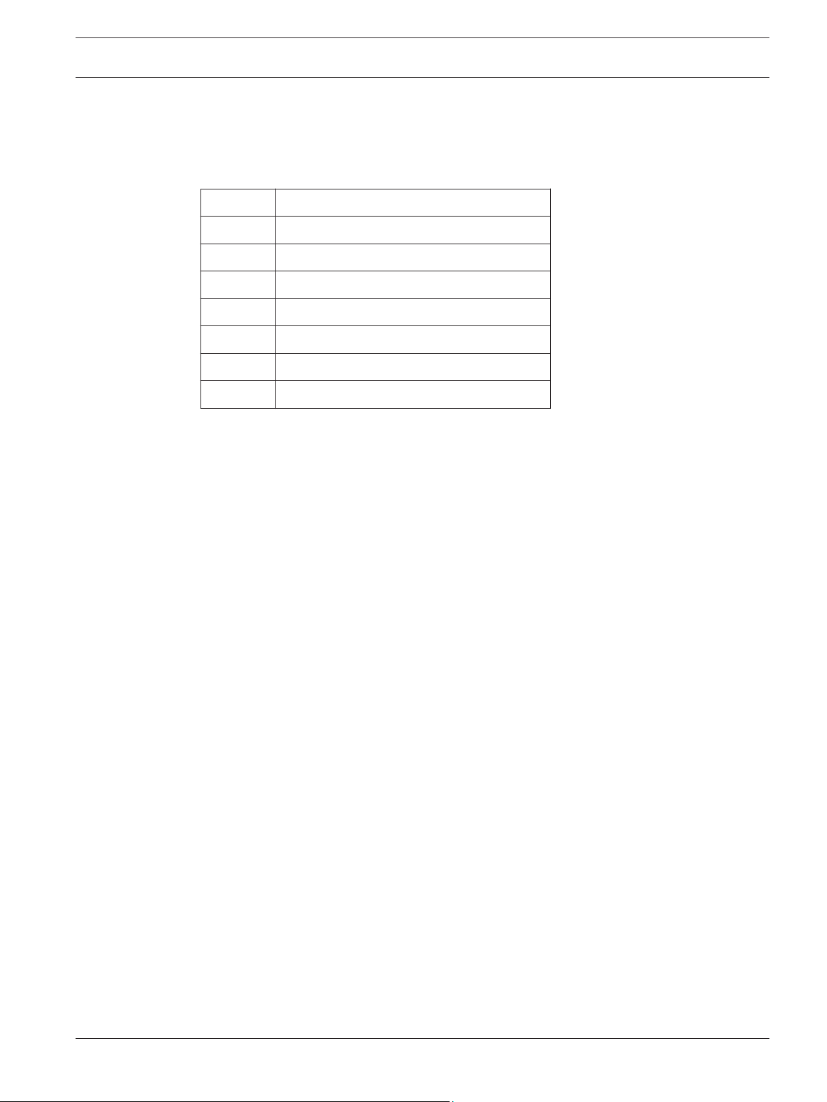
Quantity Item
1 Ceiling Bracket
1 Rubber Gasket
1 Housing Frame
1 Trim Ring
3 M4x10 Phillips Screws
1 Guide Pattern
1 Installation Manual
Bosch Security Systems, Inc. Installation Guide 2013.07 | 1.3 |
Page 8

1
2
3
4
5
6
8 en | Installing a Recessed Mount AUTODOME 5000 PTZ Camera
3.2
Installing the Recessed Mount
The illustration below shows the required parts for the recessed mount. Refer to the steps
that follow for instructions.
1 Ceiling Bracket 4 Housing Frame
2 M4x10 Screws (3 pieces) 5 Dome Camera
3 Rubber Gasket 6 Trim Ring
2013.07 | 1.3 | Installation Guide Bosch Security Systems, Inc.
Page 9

AUTODOME 5000 PTZ Camera Installing a Recessed Mount | en 9
Recessed Mount Installation Instructions
1. Find a secure location on the ceiling and apply the ceiling guide pattern the ceiling tile or
drywall. Use the pattern as a template to cut the proper circle in the ceiling.
2. Place the Ceiling Bracket (1) into the ceiling and make sure the three support wings of
the bracket are completely flush with the ceiling board.
3. Attach the Dome Camera (5) to the Housing Frame (4) by fastening the three (3) M4x10
screws.
4. Connect the Safety Tether, attached to the Ceiling Bracket (1), to the Housing Frame (4).
5. Thread all connection cables through the center hole of the Ceiling Bracket and through
the Rubber Gasket (3).
6. Connect all cables to the camera back plate.
7. Insert the Housing Frame (4) with the camera into the Ceiling Bracket (1) and securely
fasten the screws on the Housing Frame to the Ceiling Bracket.
8. Place the Trim Ring (6) over the exposed part of the camera and affix it to the Housing
Frame (4).
Bosch Security Systems, Inc. Installation Guide 2013.07 | 1.3 |
Page 10

10 en | Installing a Pipe Mount AUTODOME 5000 PTZ Camera
4
4.1
Installing a Pipe Mount
Use this chapter to install and indoor or outdoor dome camera to a pipe.
Parts List
Quantity Item
1 Pipe Mount Base with Safety Tether
1 300 mm (11.81 in.) Pipe Extension
1 200 mm (7.87 in.) Pipe Extension
1 M38 to M38 Connection Ring
1 M38 to M33 Connection Ring
1 3/4 x 260 in. Roll Teflon Tape
1 5g Container Silicon Grease
4 M10x25L Phillips Screws and Washers
1 Rubber Gasket
1 Installation Manual
2013.07 | 1.3 | Installation Guide Bosch Security Systems, Inc.
Page 11

1
2
3
4
6
5
9
8
7
AUTODOME 5000 PTZ Camera Installing a Pipe Mount | en 11
4.2
Installing the Pipe Mount
The illustration below shows the required parts for the pipe mount. Refer to the steps that
follow for instructions.
1 Pipe Mount Base 6 M38 to M33 Pipe Connector
2 M10x25L Phillips Screws (4 pieces) 7 Safety Tether
3 Pipe Extension, 300 mm (11.81 in.) 8 Adaptor
4 M38 to M38 Pipe Connector 9 Dome Camera
5 Pipe Extension, 200 mm (7.87 in.)
Bosch Security Systems, Inc. Installation Guide 2013.07 | 1.3 |
Page 12

!
12 en | Installing a Pipe Mount AUTODOME 5000 PTZ Camera
Pipe Mount Installation Instructions
Caution!
Strength of Mounting Surface
The fasteners and mounting surface must be capable of supporting a maximum load of
12 kg (26.4 pounds).
1. Locate a secure position to secure the Pipe Mount Base (1). Ensure there is an adequate
opening in the ceiling or mounting structure for the wires to pass through.
2. Use the Rubber Gasket as a template to mark the locations of the four ceiling plugs and
screws.
3. Insert the ceiling plugs (if necessary) into the wall at the locations marked in step 2.
4. Place the rubber pad between the Pipe Mount Base (1) and the ceiling. Secure the Pipe
Mount Base and the rubber pad to the ceiling or mounting structure with the four (4)
M10x25L screws and washers.
5. Apply Teflon tape to the threads on the Pipe Mount Base.
6. Apply Silicon grease over the Teflon tape on the threads on Pipe Mount Base. Ensure the
grease is spread evenly.
7. Determine the distance that the camera should hang from the ceiling or mounting
structure (200 mm, 300 mm, or 500 mm).
8. For the 200 mm or 300 mm option:
Select the appropriate Pipe Extension (3 or 5).
Fasten the Pipe Extension to the Pipe Mount Base (1).
Apply Teflon tape to both sets of threads on the M38 to M33 Connector (6).
Apply Silicon grease over the Teflon tape on both sets of threads on the M38 to M33
Connector (6). Ensure the grease is spread evenly.
Fasten the M38 to M33 Connector (6) to the bottom of the Pipe Extension.
9. For the 500 mm option:
Fasten the 300 mm Pipe Extension (3) to the Pipe Mount Base (1).
Apply Teflon tape to both sets of threads on the M38 to M38 Connector (4).
Apply Silicon grease over the Teflon tape on both sets of threads on the M38 to M38
Connector (4). Ensure the grease is spread evenly.
Fasten the M38 to M38 Connector (4) to the bottom of the 300 mm Pipe Extension. Then,
fasten the 200 mm Pipe Extension (5) to the other end of the M38 to M38 Connector.
Apply Teflon tape to both sets of threads on the M38 to M33 Connector (4).
Apply Silicon grease over the Teflon tape on both sets of threads on the M38 to M33
Connector (4). Ensure the grease is spread evenly.
Fasten the M38 to M33 Connector (6) to the bottom to the 200 mm Pipe Extension.
Notice!
Ensure that the Safety Tether (7) is routed through the Pipe Extensions and that the eyelet at
the end of the tether is through the M38 to M33 connector.
10. Fasten the Adaptor (8) to the bottom of the M38 to M33 connector.
11. Thread all connection cables from the top of the pipe mount base through the pipe
extensions and the adaptor.
12. Attach the hook at the end of the Safety Tether (7) to the loop attached to the top of the
Dome Camera (9).
13. Connect all cables to the camera back plate.
2013.07 | 1.3 | Installation Guide Bosch Security Systems, Inc.
Page 13

AUTODOME 5000 PTZ Camera Installing a Pipe Mount | en 13
14. Place the top of the Dome Camera (9) inside the Adaptor (8) and turn clockwise until the
Dome Camera latches to the Adaptor.
15. Fasten the M5x8L screw using the T20 Security Torx wrench (shipped with the camera)
to secure the Dome Camera to the Adaptor.
Bosch Security Systems, Inc. Installation Guide 2013.07 | 1.3 |
Page 14

14 en | Installing a Wall Mount AUTODOME 5000 PTZ Camera
5
5.1
Installing a Wall Mount
Use this chapter to install and indoor or outdoor dome camera to a wall.
Parts List
Quantity Item
1 Wall Mount with Safety Tether
1 3/4 x 260 in. Roll Teflon Tape
1 5g Container Silicon Grease
4 M10x25L Phillips Screws
1 Rubber Gasket
1 Installation Manual
2013.07 | 1.3 | Installation Guide Bosch Security Systems, Inc.
Page 15

AUTODOME 5000 PTZ Camera Installing a Wall Mount | en 15
5.2
Installing the Wall Mount
The illustration below shows the required parts for the wall mount. Refer to the steps that
follow for instructions.
1 Wall Mount Base 4 Safety Tether
2 Washers (4 pieces) 5 Adaptor
3 M10x25L Phillips Screws (4 pieces) 6 Dome Camera
Bosch Security Systems, Inc. Installation Guide 2013.07 | 1.3 |
Page 16

!
16 en | Installing a Wall Mount AUTODOME 5000 PTZ Camera
Wall Mount Installation Instructions
Caution!
Strength of Mounting Surface
The fasteners and mounting surface must be capable of supporting a maximum load of
12 kg (26.4 pounds).
1. Locate a secure position to secure the Wall Mount Base (1). Ensure there is an adequate
opening in the wall for the wires to pass through.
2. Use the Rubber Gasket as a template to mark the locations of the four wall plugs and
screws.
3. Insert the wall plugs (if necessary) into the wall at the locations marked in step 2.
4. Place the rubber pad between the Wall Mount Base (1) and the wall. Secure the Wall
Mount to the structure with the four (4) M10x25L screws and washers (3).
5. Apply Teflon tape to the threads on the Wall Mount Base.
6. Apply Silicon grease over the Teflon tape on the threads of the Wall Mount Base. Ensure
the grease is spread evenly.
7. Fasten the Adaptor (5) to the end of the Wall Mount.
8. Thread all connection cables through the Wall Mount.
Notice!
Ensure that the Safety Tether (4) is routed through the Wall Mount and that the eyelet at the
end of the tether is through the Adaptor.
9. Attach the hook at the end of the Safety Tether (4) to the loop attached to the top of the
Dome Camera (6).
10. Connect all cables to the camera back plate.
11. Place the top of the Dome Camera (6) inside the Adaptor (5) and turn clockwise until the
Dome Camera latches to the Adaptor.
12. Fasten the M5x8L screw using the T20 Security Torx wrench (shipped with the camera)
to secure the Dome Camera to the Adaptor.
2013.07 | 1.3 | Installation Guide Bosch Security Systems, Inc.
Page 17

AUTODOME 5000 PTZ Camera Replacing the Bubble | en 17
6
6.1
Replacing the Bubble
This section provides instructions for replacing a bubble on an AUTODOME 5000 camera.
Parts List
Quantity Item
1 Tinted Bubble with Trim Ring
(with two (2) M3x23L Torx screws attached)
1 Torx Wrench
1 Installation Manual
Bosch Security Systems, Inc. Installation Guide 2013.07 | 1.3 |
Page 18

1
2
3
18 en | Replacing the Bubble AUTODOME 5000 PTZ Camera
6.2
Installing the Replacement Bubble
Use the illustration below as a guide for replacing the bubble.
1 Safety Tab with M3x5 Screw
2 Bubble Assembly
3 M3x23L Screw (2 pieces)
2013.07 | 1.3 | Installation Guide Bosch Security Systems, Inc.
Page 19

AUTODOME 5000 PTZ Camera Replacing the Bubble | en 19
Bubble Replacement Instructions
1. Loosen the two M3x23L screws (3) from the bubble on the camera.
2. Detach the Bubble Assembly (2) from the camera.
3. Remove the screw that secures the Safety Tether to the Bubble. Keep the screw to secure
the bubble replacement.
4. Attach the Safety Tether from the camera housing to the replacement bubble using the
screw removed above.
5. Attach the replacement bubble to the camera housing.
6. Secure the replacement bubble to the camera housing with the two M3x23L Torx screws
(preinstalled in the Bubble Assembly).
Bosch Security Systems, Inc. Installation Guide 2013.07 | 1.3 |
Page 20

295.5
(11.63)
218.38
(8.6)
81.9
(3.22)
mm
(in.)
208
(8.19)
187
(7.36)
20 en | Technical data AUTODOME 5000 PTZ Camera
7
Technical data
Camera Dimensions
Figure 7.1: AUTODOME 5000 Indoor/Outdoor Dimensions
Diameter without sunshield (indoor models)
1
2 Diameter with sunshield (outdoor models)
2013.07 | 1.3 | Installation Guide Bosch Security Systems, Inc.
Page 21

Page 22

Bosch Security Systems, Inc.
850 Greenfield Road
Lancaster, PA, 17601
USA
www.boschsecurity.com
© Bosch Security Systems, Inc., 2013
 Loading...