

Page 1
DINION capture 5000 IP
NER Series
en Installation Manual
Page 2

Page 3

DINION capture 5000 IP Table of Contents | en 3
Table of Contents
1Safety 7
1.1 Safety precautions 7
1.2 Important safety instructions 8
1.3 Important notices 11
1.4 FCC & ICES compliance 15
1.5 Bosch notices 17
2 Description 18
2.1 Parts List 18
3 Installing the DINION capture 19
3.1 Determining the Range 19
3.2 Determining the Angle 20
3.3 Mounting the DINION capture 21
3.4 Preparing the Wiring 24
3.4.1 Power Input Connections 25
3.4.2 Ethernet and Power Connections 25
3.4.3 Video Connection for Installation 25
3.5 Making the Connections 26
3.6 Connecting to a Coax Cable 27
3.7 Using a microSD Card 28
3.8 Resetting the DINION capture 5000 IP 29
3.9 Automatic Mode Switching 30
4 Configuration 33
4.1 Menu Navigation Keys 33
4.2 Install Menu 33
4.2.1 Pre-Defined Modes 34
4.2.2 Lens Wizard submenu 35
4.2.3 Network submenu 36
4.2.4 Default submenu 36
5 Browser connection 37
5.1 System requirements 37
5.2 Establishing the connection 38
Bosch Security Systems, Inc. Installation Manual | 1.0 | 2012.01
Page 4

4 en | Table of Contents DINION capture 5000 IP
5.2.1 Password protection in camera 38
5.3 Protected network 38
5.4 Connecting to a hardware decoder 39
5.4.1 Alarm connection 39
5.5 Connection established 40
5.5.1 LIVEPAGE 40
5.5.2 RECORDINGS 40
5.5.3 SETTINGS 41
6 Operation via the browser 42
6.1 Livepage 42
6.1.1 Processor load 42
6.1.2 Image selection 43
6.1.3 Digital I/O 44
6.1.4 System Log / Event Log 44
6.1.5 Saving snapshots 45
6.1.6 Recording video sequences 45
6.1.7 Running recording program 45
6.1.8 Audio communication 46
6.2 Recordings page 47
6.2.1 Controlling playback 47
7 Basic Mode 49
7.1 Basic Mode menu tree 49
7.2 Device Access 50
7.2.1 Camera name 50
7.2.2 Password 50
7.3 Date/Time 51
7.4 Network 52
7.5 Encoder 53
7.6 Recording 53
7.6.1 Storage medium 53
7.7 System Overview 53
8 Advanced Mode 54
8.1 Advanced Mode menu tree 54
8.2 General 56
| 1.0 | 2012.01 Installation Manual Bosch Security Systems, Inc.
Page 5

DINION capture 5000 IP Table of Contents | en 5
8.2.1 Identification 56
8.2.2 Password 56
8.2.3 Date/Time 58
8.2.4 Display Stamping 59
8.3 Web Interface 61
8.3.1 Appearance 61
8.3.2 LIVEPAGE Functions 62
8.3.3 Logging 63
8.4 Camera 64
8.4.1 Mode 64
8.4.2 ALC 66
8.4.3 Shutter/AGC 67
8.4.4 Enhance 68
8.4.5 Encoder Profile 70
8.4.6 Encoder Streams 74
8.4.7 Privacy Masks 75
8.4.8 Audio 75
8.4.9 Installer Menu 77
8.5 Recording 78
8.5.1 Storage Management 79
8.5.2 Recording Profiles 82
8.5.3 Retention Time 83
8.5.4 Recording Scheduler 84
8.5.5 Recording Status 85
8.6 Alarm 86
8.6.1 Alarm Connections 86
8.6.2 Video Content Analyses (VCA) 89
8.6.3 VCA configuration- Profiles 90
8.6.4 VCA configuration - Scheduled 96
8.6.5 VCA configuration - Event triggered 98
8.6.6 Audio Alarm 99
8.6.7 Alarm E-Mail 100
8.6.8 Alarm Task Editor 102
8.7 Interfaces 103
8.7.1 Alarm input 103
8.7.2 Relay 103
8.8 Network 105
Bosch Security Systems, Inc. Installation Manual | 1.0 | 2012.01
Page 6

6 en | Table of Contents DINION capture 5000 IP
8.8.1 Network Access 105
8.8.2 Advanced 109
8.8.3 Multicast 110
8.8.4 FTP Posting 112
8.8.5 Encryption 113
8.9 Service 113
8.9.1 Maintenance 113
8.9.2 Licenses 115
8.9.3 System Overview 115
A Dimensional Drawings 116
| 1.0 | 2012.01 Installation Manual Bosch Security Systems, Inc.
Page 7
DINION capture 5000 IP Safety | en 7
1Safety
1.1 Safety precautions
DANGER!
High risk: This symbol indicates an imminently hazardous
situation such as "Dangerous Voltage" inside the product.
If not avoided, this will result in an electrical shock, serious
bodily injury, or death.
WARNING!
Medium risk: Indicates a potentially hazardous situation.
If not avoided, this could result in minor or moderate bodily
injury.
CAUTION!
Low risk: Indicates a potentially hazardous situation.
If not avoided, this could result in property damage or risk of
damage to the unit.
NOTICE!
This symbol indicates information or a company policy that
relates directly or indirectly to the safety of personnel or
protection of property.
Bosch Security Systems, Inc. Installation Manual | 1.0 | 2012.01
Page 8

8 en | Safety DINION capture 5000 IP
1.2 Important safety instructions
Read, follow, and retain for future reference all of the following
safety instructions. Heed all warnings on the unit and in the
operating instructions before operating the unit.
1. Cleaning - Unplug the unit from the outlet before cleaning.
Follow any instructions provided with the unit. Generally,
using a dry cloth for cleaning is sufficient but a moist, flufffree cloth or leather shammy may also be used. Do not use
aerosol cleaners.
2. Heat Sources - Do not install the unit near any heat
sources such as radiators, heaters, stoves, or other
equipment (including amplifiers) that produce heat.
3. Object and liquid entry - Never push objects of any kind
into this unit through openings as they may touch
dangerous voltage points or short-out parts that could
result in a fire or electrical shock. Never spill liquid of any
kind in the unit.
4. Lightning - For added protection during a lightning storm,
or when leaving this unit unattended and unused for long
periods, unplug the power source and disconnect the
cable system. This will prevent damage to the unit from
lightning and power line surges.
5. Controls adjustment - Adjust only those controls specified
in the operating instructions. Improper adjustment of
other controls may cause damage to the unit. Use of
controls or adjustments, or performance of procedures
other than those specified, may result in hazardous
radiation exposure.
6. Overloading - Do not overload circuits. This can cause fire
or electrical shock.
7. Power cable protection - Protect the power cable from
foot traffic, from being pinched by items placed upon it,
and at cable's exit from the unit.
| 1.0 | 2012.01 Installation Manual Bosch Security Systems, Inc.
Page 9

DINION capture 5000 IP Safety | en 9
8. Power disconnect - Units have power supplied to the unit
whenever the power cord is inserted into the power
source. The power cord plug is the main power disconnect
device for switching off the voltage for all units.
9. Power sources - Operate the unit only from the type of
power source indicated on the label. Before proceeding,
be sure to disconnect the power from the cable to be
installed into the unit.
– For external power supplied units, use only the
recommended or approved power supplies.
– For limited power source units, this power source
must comply with EN60950. Substitutions may
damage the unit or cause fire or shock.
– For 24 VAC units, voltage applied to the unit's power
input should not exceed ±10%, or 26.4 VAC. Usersupplied wiring must comply with local electrical
codes (Class 2 power levels). Do not ground the
supply at the terminals or at the unit's power supply
terminals.
– If unsure of the type of power supply to use, contact
your dealer or local power company.
10. Servicing - Do not attempt to service this unit yourself.
11. Damage requiring service - Unplug the unit from the main
AC power source and refer servicing to qualified service
personnel when any damage to the equipment has
occurred, such as:
– the power supply cord or plug is damaged;
– internal exposure to moisture, water, and/or
inclement weather (rain, snow, etc.);
– liquid has been spilled in the equipment;
– an object has fallen into the unit;
– unit has been dropped;
– unit exhibits a distinct change in performance;
– unit does not operate normally when the user
correctly follows the operating instructions.
Bosch Security Systems, Inc. Installation Manual | 1.0 | 2012.01
Page 10

10 en | Safety DINION capture 5000 IP
12. Replacement parts - Be sure the service technician uses
replacement parts specified by the manufacturer, or that
have the same characteristics as the original parts.
Unauthorized substitutions may cause fire, electrical
shock, or other hazards.
13. Safety check - Safety checks should be performed upon
completion of service or repairs to the unit to ensure
proper operating condition.
14. Installation - Install in accordance with the manufacturer's
instructions and in accordance with applicable local codes.
15. Attachments, changes or modifications - Only use
attachments/accessories specified by the manufacturer.
Any change or modification of the equipment, not
expressly approved by Bosch, could void the warranty or,
in the case of an authorization agreement, authority to
operate the equipment.
| 1.0 | 2012.01 Installation Manual Bosch Security Systems, Inc.
Page 11
DINION capture 5000 IP Safety | en 11
1.3 Important notices
Accessories - Do not place this unit on an unstable stand,
tripod, bracket, or mount. The unit may fall and cause serious
injury and/or serious damage to the unit. Use only with the
cart, stand, tripod, bracket, or table specified by the
manufacturer. When a cart is used, use caution and care when
moving the cart/apparatus combination to avoid injury from
tip-over. Quick stops, excessive force, or uneven surfaces may
cause the cart/unit combination to overturn. Mount the unit
per the manufacturer's instructions.
All-pole power switch - Incorporate an all-pole power switch,
with a contact separation of at least 3 mm in each pole, into the
electrical installation of the building. If it is needed to open the
housing for servicing and/or other activities, use this all-pole
switch as the main disconnect device for switching off the
voltage to the unit.
Camera signal - Protect the cable with a primary protector if
the camera signal is beyond 140 feet, in accordance with
NEC800 (CEC Section 60).
NOTICE!
RISK GROUP 1
IR emitted from this product.
This product has been tested according to standard CIE/IEC
62471:2006 “Photobiological safety of lamps and lamp
systems” and found to meet Risk Group 1 for exposure limit
4.3.7 “Infrared radiation hazard exposure limits for the eye.”
For other hazard exposure limits, the product was found to be
exempt. Risk Group 1 is characterized in the standard as
“products are safe for most use applications, except for very
prolonged exposures where direct ocular exposures may be
expected.” Risk Group 1 sources do not pose an infrared
radiation hazard for the eye for times less than 100 s at
distances beyond 200 mm or 8 inches.
Bosch Security Systems, Inc. Installation Manual | 1.0 | 2012.01
Page 12

12 en | Safety DINION capture 5000 IP
The Exposure Hazard Value for the product (ratio of the
Exposure level to the Exposure limit) is up to 1.8 at a test
distance of 200 mm or 8 inches. The Hazard Distance (distance
beyond which the product falls into the exempt/safe group) is
at most 350 mm or 14 inches. Note that typical operating
distances for license plate capture (3.8 m or 12.5 feet and
greater) are much greater than the Hazard Distance.
When servicing the unit, physically disconnect the power supply
to avoid possible IR exposure to the eyes. If physical
disconnection is not possible, use appropriate shielding to
block the LED panel or use eye protection with a transmission
of 50% or less at a wavelength of 850 nm.
Coax grounding:
– Ground the cable system if connecting an outside cable
system to the unit.
– Follow proper safety precautions such as grounding for
any outdoor device connected to this unit.
U.S.A. models only - Section 810 of the National Electrical Code,
ANSI/NFPA No.70, provides information regarding proper
grounding of the mount and supporting structure, grounding of
the coax to a discharge unit, size of grounding conductors,
location of discharge unit, connection to grounding electrodes,
and requirements for the grounding electrode.
Disposal - Your Bosch product was developed and
manufactured with high-quality material and components that
can be recycled and reused. This symbol means that electronic
and electrical appliances, which have reached the end of their
working life, must be collected and disposed of separately
from household waste material. Separate collecting systems
are usually in place for disused electronic and electrical
products. Please dispose of these units at an environmentally
compatible recycling facility, per European Directive 2002/96/
EC
Electronic Surveillance - This device is intended for use in
public areas only. U.S. federal law strictly prohibits
surreptitious recording of oral communications.
| 1.0 | 2012.01 Installation Manual Bosch Security Systems, Inc.
Page 13

DINION capture 5000 IP Safety | en 13
Environmental statement - Bosch has a strong commitment
towards the environment. This unit has been designed to
respect the environment as much as possible.
Electrostatic-sensitive device - Use proper CMOS/MOS-FET
handling precautions to avoid electrostatic discharge.
NOTE: Wear required grounded wrist straps and observe proper
ESD safety precautions when handling the electrostaticsensitive printed circuit boards.
Fuse rating - For protection of the device, the branch circuit
protection must be secured with a maximum fuse rating of 16A.
This must be in accordance with NEC800 (CEC Section 60).
Moving - Disconnect the power before moving the unit. Move
the unit with care. Excessive force or shock may damage the
unit.
Outdoor signals - The installation for outdoor signals, especially
regarding clearance from power and lightning conductors and
transient protection, must be in accordance with NEC725 and
NEC800 (CEC Rule 16-224 and CEC Section 60).
Permanently connected equipment - Incorporate a readily
accessible disconnect device external to the equipment.
Pluggable equipment - Install the socket outlet near the
equipment so it is easily accessible.
PoE Plus - Use only approved PoE Plus devices.
By default, power is supplied to the camera via the standard
(11-30 VDC or 24 VAC) power connection. If connection is
made via the Ethernet cable, compliant with the Power-overEthernet (IEEE 802.3at Type 2) standard at the same time as
the standard connection, the standard connection will prevail
without damage to the device. To use PoE Plus, standard power
must be turned off.
Bosch Security Systems, Inc. Installation Manual | 1.0 | 2012.01
Page 14

14 en | Safety DINION capture 5000 IP
Power lines: An outdoor system should not be located in the
vicinity of overhead power lines, electrical lights, or power
circuits, or where it may contact such power lines or circuits.
When installing an outdoor system, extreme care should be
taken to keep from touching power lines or circuits, as this
contact may be fatal.
U.S.A. models only - refer to the National Electrical Code Article
820 regarding installation of CATV systems.
11-30 VDC / 24 VAC power source: This device is intended to
operate with a limited power source; this power source must
comply with EN60950. The device is designed to operate at
either 11-30 VDC or 24 VAC (if PoE is not available). User
supplied wiring must be in compliance with electrical codes
(Class 2 power levels). If 24 VAC is used, do not ground the
24 VAC supply at the terminals or at the device's power supply
terminals.
Connections: The unit has connection terminals on flying leads.
In wet or outdoor installations use a field wiring box with NEMA
3 or IP55 protection level or better. Make the connections
inside the water tight compartment. After connections are
made ensure that the watertight compartment is tightly closed
and cables and conduits are properly sealed to prevent ingress
of water.
SELV - All the input/output ports are Safety Extra Low Voltage
(SELV) circuits. SELV circuits should only be connected to
other SELV circuits.
Because ISDN circuits are treated like telephone-network
voltage, avoid connecting the SELV circuit to the Telephone
Network Voltage (TNV) circuits.
| 1.0 | 2012.01 Installation Manual Bosch Security Systems, Inc.
Page 15

DINION capture 5000 IP Safety | en 15
1.4 FCC & ICES compliance
FCC & ICES Information
(U.S.A. and Canadian Models Only)
This device complies with part 15 of the FCC Rules. Operation is
subject to the following conditions:
– this device may not cause harmful interference, and
– this device must accept any interference received,
including interference that may cause undesired operation.
NOTE: This equipment has been tested and found to comply
with the limits for a Class A digital device, pursuant to Part 15
of the FCC Rules and ICES-003 of Industry Canada. These limits
are designed to provide reasonable protection against harmful
interference when the equipment is operated in a commercial
environment. This equipment generates, uses, and radiates
radio frequency energy and, if not installed and used in
accordance with the instruction manual, may cause harmful
interference to radio communications. Operation of this
equipment in a residential area is likely to cause harmful
interference, in which case the user will be required to correct
the interference at his expense.
Intentional or unintentional modifications, not expressly
approved by the party responsible for compliance, shall not be
made. Any such modifications could void the user's authority to
operate the equipment. If necessary, the user should consult
the dealer or an experienced radio/television technician for
corrective action.
The user may find the following booklet, prepared by the
Federal Communications Commission, helpful: How to Identify
and Resolve Radio-TV Interference Problems. This booklet is
available from the U.S. Government Printing Office,
Washington, DC 20402, Stock No. 004-000-00345-4.
Informations FCC et ICES
(modèles utilisés aux États-Unis et au Canada uniquement)
Ce produit est conforme aux normes FCC partie 15. la mise en
service est soumises aux deux conditions suivantes :
Bosch Security Systems, Inc. Installation Manual | 1.0 | 2012.01
Page 16

16 en | Safety DINION capture 5000 IP
– cet appareil ne peut pas provoquer d'interférence nuisible
et
– cet appareil doit pouvoir tolérer toutes les interférences
auxquelles il est soumit, y compris les interférences qui
pourraient influer sur son bon fonctionnement.
AVERTISSEMENT: Suite à différents tests, cet appareil s’est
révélé conforme aux exigences imposées aux appareils
numériques de Classe A en vertu de la section 15 du règlement
de la Commission fédérale des communications des États-Unis
(FCC). Ces contraintes sont destinées à fournir une protection
raisonnable contre les interférences nuisibles quand l'appareil
est utilisé dans une installation commerciale. Cette appareil
génère, utilise et émet de l'energie de fréquence radio, et peut,
en cas d'installation ou d'utilisation non conforme aux
instructions, générer des interférences nuisibles aux
communications radio. L’utilisation de ce produit dans une
zone résidentielle peut provoquer des interférences nuisibles.
Le cas échéant, l’utilisateur devra remédier à ces interférences
à ses propres frais.
Au besoin, l’utilisateur consultera son revendeur ou un
technicien qualifié en radio/télévision, qui procédera à une
opération corrective. La brochure suivante, publiée par la
Commission fédérale des communications (FCC), peut s’avérer
utile : How to Identify and Resolve Radio-TV Interference Problems
(Comment identifier et résoudre les problèmes d’interférences
de radio et de télévision). Cette brochure est disponible auprès
du U.S. Government Printing Office, Washington, DC 20402,
États-Unis, sous la référence n° 004-000-00345-4.
NOTICE!
This is a class A product. In a domestic environment this
product may cause radio interference, in which case the user
may be required to take adequate measures.
| 1.0 | 2012.01 Installation Manual Bosch Security Systems, Inc.
Page 17

DINION capture 5000 IP Safety | en 17
1.5 Bosch notices
Video loss
Video loss is inherent to digital video recording; therefore,
Bosch Security Systems cannot be held liable for any damage
that results from missing video information. To minimize the
risk of lost digital information, Bosch Security Systems
recommends multiple, redundant recording systems, and a
procedure to back up all analog and digital information.
Copyright
This manual is the intellectual property of Bosch Security
Systems and is protected by copyright. All rights reserved.
Trademarks
All hardware and software product names used in this
document are likely to be registered trademarks and must be
treated accordingly.
Note:
This manual has been compiled with great care and the
information it contains has been thoroughly verified. The text
was complete and correct at the time of printing. The ongoing
development of the products may mean that the content of the
user guide can change without notice. Bosch Security Systems
accepts no liability for damage resulting directly or indirectly
from faults, incompleteness, or discrepancies between the user
guide and the product described.
More information
For more information please contact the nearest Bosch Security
Systems location or visit www.boschsecurity.com
Bosch Security Systems, Inc. Installation Manual | 1.0 | 2012.01
Page 18

18 en | Description DINION capture 5000 IP
2 Description
The DINION capture is a specialty camera designed to capture
consistent, high-quality images of vehicle license plates.
Available in IP and analog versions, it is ideal for monitoring
parking lots, public areas, and for controlling vehicle access.
The DINION capture overcomes the problems encountered
when using conventional surveillance cameras in vehicle
identification and automatic license plate recognition
applications. The Night Capture Imaging System delivers a
burst of infrared illumination and simultaneously filters out
visible light to ensure clear license plate images in complete
darkness while eliminating the negative effects of headlight
glare.
Advanced Ambient Compensation minimizes plate
overexposure from sunlight for more accurate automatic license
plate recognition. Finally, adjustable imaging modes allow for
fine-tuning the imager for specific regions or license plate
recognition algorithms.
2.1 Parts List
Quantity Description
1 DINION capture 5000 IP
1 3 mm Hex Key
1 5 mm Hex Key
1 Mounting Template
1 CD, containing product documentation and
support files
| 1.0 | 2012.01 Installation Manual Bosch Security Systems, Inc.
Page 19

DINION capture 5000 IP Installing the DINION capture | en 19
3 Installing the DINION capture
This section provides instructions for mounting and wiring the
DINION capture.
CAUTION!
The selected mounting location should not place the camera in
a situation where its environmental specifications could be
exceeded.
Ensure the selected location is protected from falling objects,
accidental contact with moving objects, and unintentional
interference from personnel. Follow all applicable building
codes.
3.1 Determining the Range
The DINION capture has a recommended operation range with
specified optimal capture distance for each model as shown
below. Installation should aim to control the traffic through one
lane.
Ranges based on capturing:
520 x 115 mm (approximate) license plates on PAL units
(xER-L2Ry-1)
12 x 6 in. (approximate) license plates on NTSC units
(xER-L2Ry-2)
Field of View at Optimal Capture Distance:
2.8 x 2.1 m (PAL units)
6 ft 6 in. x 4 ft 11 in. (NTSC units)
Bosch Security Systems, Inc. Installation Manual | 1.0 | 2012.01
Page 20

20 en | Installing the DINION capture DINION capture 5000 IP
Model Capture
Range
NER-L2R1-1 3.8–6.4 m
NER-L2R1-2 23.0° 17.3°
(12.5–21.0 ft)
NER-L2R2-1 5.5–9.1 m
NER-L2R2-2 16.0° 12.0°
(18–30 ft)
NER-L2R3-1 7.9–13.7 m
NER-L2R3-2 11.1° 8.3°
(26–45 ft)
NER-L2R4-1 11.3–19.5 m
NER-L2R4-2 7.7° 5.8°
(37–64 ft)
NER-L2R5-1 16.5–28.0 m
NER-L2R5-2 5.3° 4.0°
Table 3.1 Ranges for DINION capture 5000 IP Imagers
(54–92 ft)
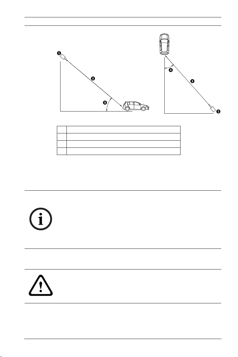
3.2 Determining the Angle
The maximum mounting angle of the license plate camera to the
car is 40° for speeds up to 160 km/h (100 mph), both
horizontally and vertically. This angle limits the amount of skew
of the letters on the number plate. If the letters are skewed too
much they will start to become unrecognizable and will reduce
automatic software recognition rates.
For maximum performance ensure the mounting angle is as
narrow as possible. To capture vehicle speeds up to 225 km/h
(140 mph) the horizontal and vertical mounting angle should be
less than 30°.
Optimal
Distance
4.9 m
(16.0 ft)
7.1 m
(23.1 ft)
10.2 m
(33.5 ft)
14.8 m
(48.4 ft)
21.3 m
(70.0 ft)
HFOV VFOV
31.9° 24.2°
22.3° 16.8°
15.6° 11.8°
10.8° 8.1°
7.5° 5.6°
| 1.0 | 2012.01 Installation Manual Bosch Security Systems, Inc.
Page 21
DINION capture 5000 IP Installing the DINION capture | en 21
Figure 3.1 Recommended Vertical and Horizontal Mounting Angle
1 DINION capture
2 Capture Range
3 Vertical Mounting Angle
4 Horizontal Mounting Angle
If the maximum range is exceeded, then the letters become
smaller and more difficult to read. At the maximum range and
angle the width of the number plate covers approximately 12%
of the width of the screen.
NOTICE!
The Capture Range is the distance from the license plate
camera to the license plate. Working below the optimal capture
distance allows a larger area for number plates and more
accurate recognition but less lane area can be covered. If the
imager is too close to the license plate, the plate could
disappear from the field of view before it is captured.
3.3 Mounting the DINION capture
CAUTION!
Installation should only be performed by a qualified service
professional in accordance with the National Electrical Code or
applicable local codes.
For a secure mounting installation, bolts should extend through
the mounting surface and be secured with nuts, washers, and
lock washers on the opposite side. If studs are used, they
Bosch Security Systems, Inc. Installation Manual | 1.0 | 2012.01
Page 22
22 en | Installing the DINION capture DINION capture 5000 IP
should be anchored in concrete or welded to a steel backer
plate.
Refer to the MBE Mounts and Adapters Installation Guide for
more details about attaching the bracket to an MBE-15 Pole
Mount Adapter or to the MBE-17 Wall Mount Adapter.
1. Use the wall mount template supplied in the packaging box
to locate the four mounting holes for the camera bracket.
2. Drill four (4) holes for the mounting bolts. If installing
outdoors, apply a weatherproof sealant around each hole
at the mounting surface.
3. Route the cable. If routing the cable through the wall, drill
a 25.4 mm (1 in.) hole following the wall mount template
and use a weatherproof sealant to seal around the cable to
ensure a weather tight seal between indoors and outdoors,
otherwise route the cable through one of the side holes in
the mounting bracket by removing the plug and routing the
cable through.
WARNING!
A stud/bolt diameter of 6.0 mm (or 1/4 inch) able to withstand
a 300 kg (660 lb) pull-out force is recommended. The mounting
material must be able to withstand this pull out force.
4. Secure the mounting bracket to the mounting surface. Use
four (4) corrosion-resistant, stainless steel studs or bolts,
nuts, washers, and lock washers (not supplied).
5. Adjust the license plate camera angle using the range and
angle recommendations in Section 3.1 Determining the
Range, page 19.
– Connect the imager to a local monitor to assist
adjusting the license plate camera. For DINION
capture 5000 IP cameras, refer to Section 3.4.3 Video
Connection for Installation, page 25.
| 1.0 | 2012.01 Installation Manual Bosch Security Systems, Inc.
Page 23
DINION capture 5000 IP Installing the DINION capture | en 23
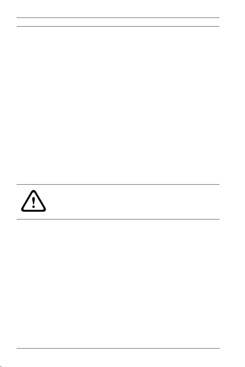
6. Adjust the tilt angle of the camera by loosening the tilt bolt
(item 1, below) with the 5 mm hex key and the set screw
(item 2) with a flat head screwdriver.
7. Place the license plate camera at the desired tilt angle and
tighten the tilt bolt and the set screw.
8. Adjust the pan angle of the camera by loosening the pan
bolt, located beneath the bracket mounting head, by
loosening the pan bolt using the 5 mm hex key. Place the
license plate camera at the desired pan angle and tighten
the bolt.
Bosch Security Systems, Inc. Installation Manual | 1.0 | 2012.01
Page 24
24 en | Installing the DINION capture DINION capture 5000 IP
NOTICE!
For purposes of evaluation and testing of the mounting
bracket's integrity under static loading at CSA, the unit was
mounted to a drywall surface as per the procedures below:
– Locate a stud in the wall and mark the outside edges of the
stud.
– Using the wall mount bracket as a template, align the
mounting hole with the center of the stud.
– Mark the point on the wall in the center of the hole where
the mounting bolt will be positioned.
– Remove the wall mount bracket and drill a pilot hole at the
marked point.
– Align the wall mount bracket mounting hole with the hole
drilled in the wall.
– Using a screwdriver, secure the wall mount bracket by
screwing a 2.5 in. screw with washer securely into the
stud.
– Follow this procedure to attach the three remaining
screws.
NOTICE!
The camera has not been evaluated for safety requirements
using other mounting kits.
3.4 Preparing the Wiring
CAUTION!
Before proceeding, disconnect the power from the power
supply cable. Ensure that the voltage of the unit matches the
voltage and type of the power supply being used.
The DINION capture 5000 IP is pre-wired with a 2-m long power
input lead and 10/100 Ethernet cable with a male RJ45
connection. The DINION capture 5000 IP can accept power via
the Ethernet cable compliant with the Power-over-Ethernet+
(PoE+ IEEE 802.3at) standard or from a Class 2 power supply.
| 1.0 | 2012.01 Installation Manual Bosch Security Systems, Inc.
Page 25

DINION capture 5000 IP Installing the DINION capture | en 25
3.4.1 Power Input Connections
A voltage regulator circuit allows for DC or AC operation
between 11-30 VDC and 24 VAC. It also provides protection
from voltage surges, transient spikes, and reversed voltage.
Connect power from a 24 VAC or 11–30 VDC Class 2 power
supply to the ferrule tipped power leads (red, black) from the
camera. Use minimum AWG18 stranded wire.
Note:
For a Class 2 AC/DC supply the polarity does not matter.
3.4.2 Ethernet and Power Connections
– Connect the camera to a 10/100 Base-T network.
– Use screened UTP Category 5e cable with RJ45 connectors
(the camera network socket is Auto MDIX compliant).
– Power can be supplied to the camera via the Ethernet
cable compliant with the Power-over-Ethernet Plus
(IEEE 802.3at) standard.
Three power options, PoE+, 24 VAC, and 11–30 VDC are
available. Using PoE+ makes installation easier and more costeffective, as cameras do not require a local power source. To
increase system reliability, the camera can be simultaneously
connected to both PoE+ and 11-30 VDC/24 VAC supplies.
By default, power is supplied to the camera via the 11–30 VDC
or 24 VAC power input leads.
3.4.3 Video Connection for Installation
To assist in setting up the camera, the DINION capture 5000 IP
provides a BNC connect on the back panel. Use this BNC
connector to temporarily connect a monitor to the IP camera,
refer to Section 3.6 Connecting to a Coax Cable, page 27.
Bosch Security Systems, Inc. Installation Manual | 1.0 | 2012.01
Page 26

26 en | Installing the DINION capture DINION capture 5000 IP
3.5 Making the Connections
WARNING!
Before proceeding, disconnect the power from the power
supply cable. Ensure that the voltage of the unit matches the
voltage and type of the power supply being used.
The easiest way to connect the cables is as follows:
1. Bring the building connections through the surface cable
hole so that they hang clear.
2. Connect the Ethernet cable with connector to RJ-45 jack
coming from the DINION capture 5000 IP.
3. Connect the ferrule tipped power wires (red, black;
polarity independent) to the power supply connection if
power is not supplied via PoE+ over the Ethernet cable.
Note: You can connect the imager to a PoE+ and to an 1130 VDC / 24 VAC supply simultaneously.
4. In damp environments ensure that the connections are
sealed inside a junction box or a field wiring box with
NEMA 3 or IP55 protection level or better. Make the
connections inside the water tight compartment. After
connections are made ensure that the watertight
compartment is tightly closed and cables and conduits are
properly sealed to prevent ingress of water.
| 1.0 | 2012.01 Installation Manual Bosch Security Systems, Inc.
Page 27
DINION capture 5000 IP Installing the DINION capture | en 27
3.6 Connecting to a Coax Cable
You can temporarily connect the DINION capture 5000 IP to a
monitor via a coax cable to view the transmitted image for
setup and testing purposes.
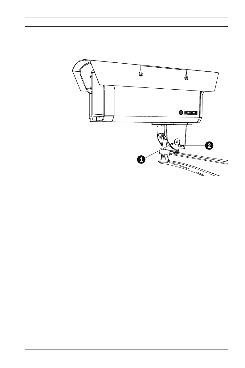
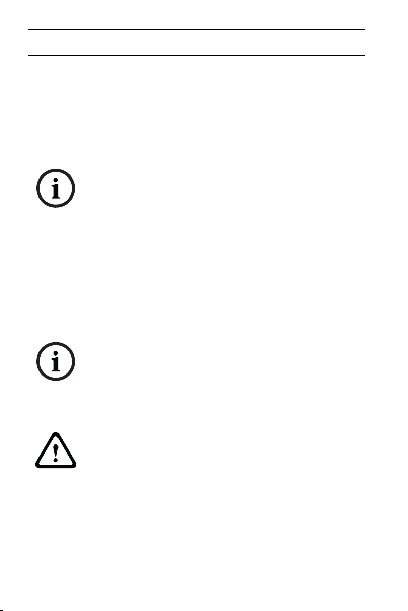
1. Remove the four (4) hex socket screws from the back
panel using the supplied 3 mm hex key.
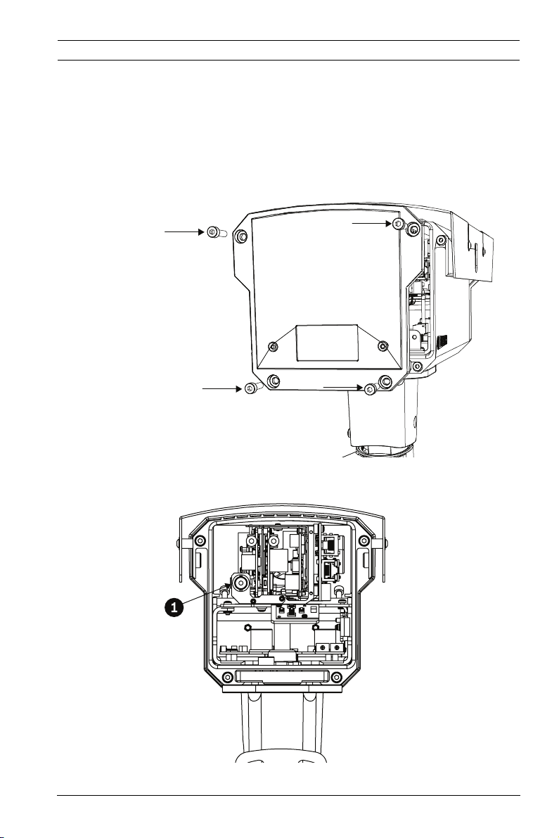
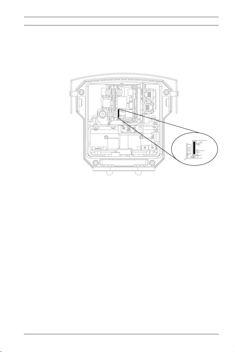
2. Locate the BNC connector (item 1, below) inside the
imager and connect a coax cable.
Bosch Security Systems, Inc. Installation Manual | 1.0 | 2012.01
Page 28
28 en | Installing the DINION capture DINION capture 5000 IP
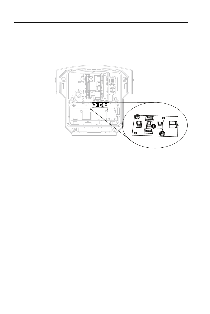
3. Connect the other end of the coax cable to a monitor.
4. Ensure that power is restored to the imager.
5. Press and hold the center key (item 2) for approximately
two seconds. The BNC video output is activated and the
Install menu appears on the monitor.
6. Adjust settings and setup camera positioning as required.
7. Press and hold the center key a second time to return the
video signal back to the Ethernet connection. Release the
button once the BNC connection loses the video signal.
8. Replace the back panel using the four hex socket screws
and the supplied 3 mm hex key.
3.7 Using a microSD Card
The DINION capture 5000 IP supports most microSD cards
(SDHC). For a list of recommended cards (not supplied by
Bosch), please visit www.boschsecurity.com.
To insert a microSD card:
| 1.0 | 2012.01 Installation Manual Bosch Security Systems, Inc.
Page 29
DINION capture 5000 IP Installing the DINION capture | en 29
1. Remove the back panel of the DINION capture 5000 IP.
Refer to Section 3.6 Connecting to a Coax Cable, page 27 for
instructions.
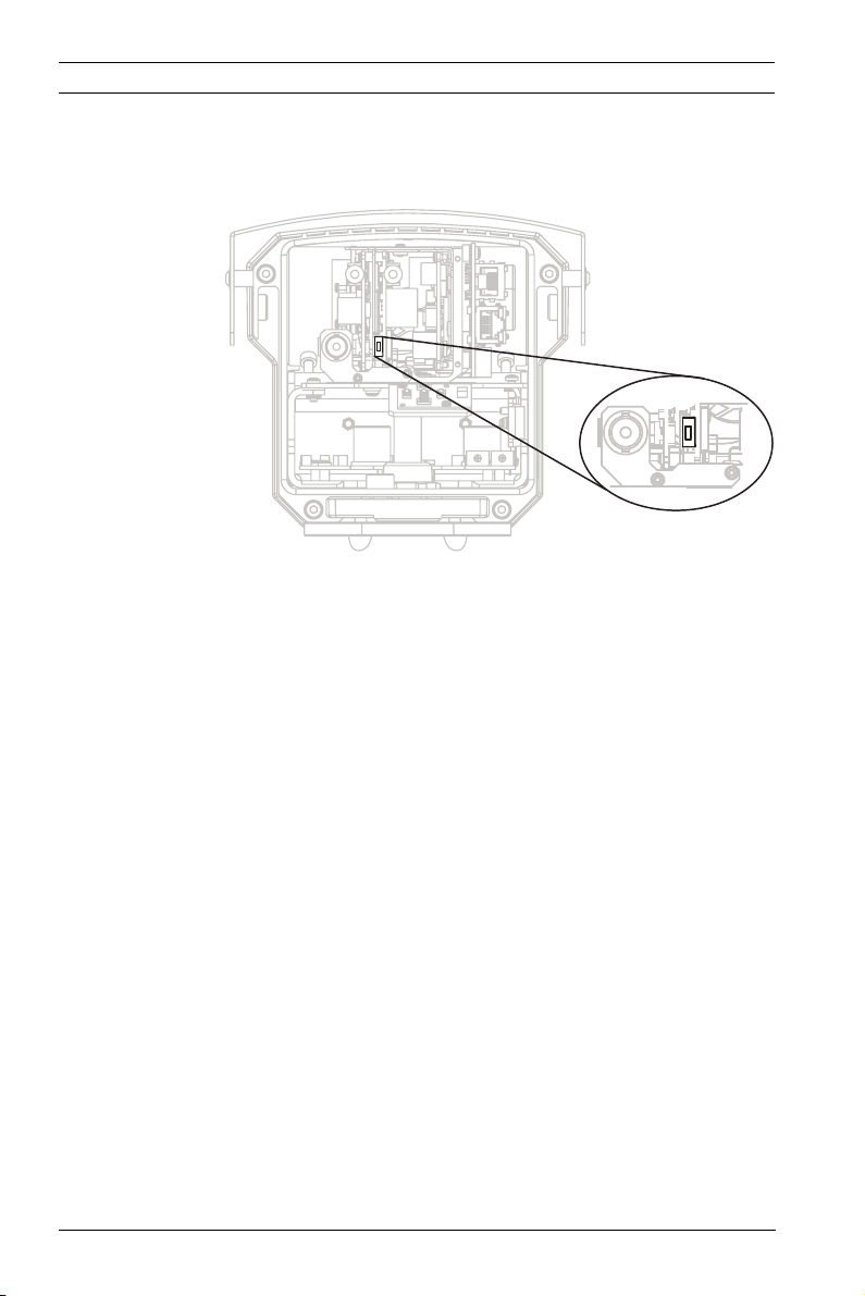
2. Slide the SD card into the slot, located near the center of
the imager.
3. Replace the rear panel.
4. Refer to Section 8.5 Recording, page 78, for more
information on using the microSD card.
3.8 Resetting the DINION capture 5000 IP
You may need to restore the default IP address or restore a
previous version of the Bosch Video over IP (BVIP) firmware on
the DINION capture 5000 IP.
To reset the imager:
Bosch Security Systems, Inc. Installation Manual | 1.0 | 2012.01
Page 30
30 en | Installing the DINION capture DINION capture 5000 IP
1. Remove the back panel. Refer to Section 3.6 Connecting to
a Coax Cable, page 27 for instructions.
2. Locate the reset button, towards the center of the imager.
3. With the power on, press and hold the reset button for
more than ten (10) seconds to restore the factory defaults.
4. Replace the rear panel.
3.9 Automatic Mode Switching
Automatic Mode Switching is a feature on the license plate
camera that automatically compensates for bright conditions.
Automatic Mode Switching, by default, operates by switching
from Mode 1 (Normal) to Mode 2 (FullSun) when the ambient
light levels rise above normal conditions (for example, bright
sunlight on the scene). Automatic Mode Switching is inactive by
default and requires setup to operate as desired.
In most conditions, Automatic Mode Switching may not be
necessary. Activate the switch only if the license plate camera
operates as desired during darker conditions but overexposes
the image during sunny conditions.
IMPORTANT: Only setup Automatic Mode Switching if the
target license plate is in the sun and the captured image is
overexposed, never setup if the license plate is in the shade.
| 1.0 | 2012.01 Installation Manual Bosch Security Systems, Inc.
Page 31

DINION capture 5000 IP Installing the DINION capture | en 31
Mode Details
Mode 2 (FullSun) is two (2) gain points less than the normal
mode, by default. You can modify both mode settings as
needed in order to provide the desired image throughout the
day.
When modifying settings, first verify which mode is active by
clicking the Settings link at the top of the page. Then click on
Advanced Mode and navigate to
Camera>PictureSettings>Mode. The active model shows in the
Current Modedrop down box.
If changes are made to Mode 1 (Normal) ensure that the offset
change is made to Mode 2 (FullSun). For example, if the plate
image is too bright in Mode 1 (Normal) and you change the gain
from 8 to 6, then you should change the gain in Mode 2
(FullSun) from 6 to 4.
Important:
After changes are made to any settings ensure the DINION
capture is left in mode 1 under Camera>Picture Settings (refer
to Section 8.4.1 Mode, page 64).
To setup Automatic Mode Switching:
1. Ensure to setup during the brightest conditions of the day,
the plate image should appear very bright before setup.
2. Remove the back panel of the housing and locate the
potentiometer on the right.
Bosch Security Systems, Inc. Installation Manual | 1.0 | 2012.01
Page 32

32 en | Installing the DINION capture DINION capture 5000 IP
3. Navigate to the Livepage for the camera (refer to
Section 6 Operation via the browser, page 42) and observe
the Input 1 symbol.
4. Slowly turn the potentiometer counter-clockwise until the
Input 1 symbol lights up. The camera is now in Mode 2
(FullSun) and the image appears dimmed slightly.
5. If the image is still too bright, navigate to the Settings page
for the camera.
– From the Livepage, click the Settings link at the top of
the page.
– Click the Advanced Mode link, then navigate to
Camera>Picture Settings>Shutter/AGC.
– Lower the Fixed gain setting until the desired image is
achieved.
– If the lowest gain setting is reached and the image is
still too bright try changing the shutter to 1/10000.
To disable Automatic Mode Switching:
1. Navigate to the Settings page for the camera, under the
Advanced Mode link, click the Interfaces link, then click
Alarm Inputs.
2. Select None for the Action option. Refer to
Section 8.7.1 Alarm input, page 103, for more information.
NOTICE!
Shutter can also be changed to adjust plate brightness. Shutter
is fixed at 1/5000 from the factory and should be changed only
by an experienced user. Changing the shutter speed affects
maximum capture speed of the vehicle and ambient rejection
ability.
| 1.0 | 2012.01 Installation Manual Bosch Security Systems, Inc.
Page 33

DINION capture 5000 IP Configuration | en 33
4 Configuration
Configuration of the DINION capture 5000 IP is carried out
remotely via the network using a web browser. However, the
license plate camera also has a set-up menu in which basic
installation settings can be accessed. To view this menu,
connect a monitor to the composite video output of the camera
(refer to Section 3.6 Connecting to a Coax Cable, page 27).
4.1 Menu Navigation Keys
Five keys are used for navigating through menu system.
– Use the up or down keys to scroll through a menu.
– Use the left or right keys to move through options or to set
parameters.
– When in a menu, quickly double-press the menu/select key
to restore the selected item to its factory default.
– To close all menus at once hold down the menu/select key
until the menu display disappears or continually select the
Exit item.
Some menus automatically close after about two minutes; other
menus have to be closed manually.
4.2 Install Menu
When the Install menu is opened, the MAC address of the unit
is shown. This is factory set and cannot be changed. The items
in the menu include the Mode selection, the Lens Wizard
submenu, the Network submenu, and the Defaults submenu.
Note: License plate camera parameter set-up is done via the
web browser interface.
Bosch Security Systems, Inc. Installation Manual | 1.0 | 2012.01
Page 34

34 en | Configuration DINION capture 5000 IP
4.2.1 Pre-Defined Modes
There are six operating modes settings to make configuration
easier. Normal and FullSun modes are pre-programmed to work
with Automatic Mode Switching. Any one of the six modes can
be selected as the "switch-to" mode in Automatic Mode
Switching, refer to Section 8.7.1 Alarm input. The modes are
defined as follows:
1. Normal (Mode 1)
Default installation mode to provide stable pictures over a
24-hour period. These settings are optimized for out-ofthe-box installation.
2. FullSun (Mode 2)
Reduced gain to provide properly exposed image during
bright conditions.
3. Mode 3
Default settings.
4. Mode 4
Default settings.
5. Mode 5
Default settings.
6. Mode 6
Default settings.
| 1.0 | 2012.01 Installation Manual Bosch Security Systems, Inc.
Page 35

DINION capture 5000 IP Configuration | en 35
4.2.2 Lens Wizard submenu
NOTICE!
Lens is factory calibrated and does not require any
adjustments.
Item Selection Description
Lens type Auto,
Manual, DCiris, Video
Auto: automatically selects the type of
lens.
Manual, DC-iris, Video modes: select
the matching lens type to force the
camera to the correct lens mode.
Detected Shows the type of lens detected when
auto lens detection is used.
Set Backfocus
now
Select to fully open the iris. Follow the
instructions below for setting the
backfocus for your particular lens type.
After focusing the object of interest
remains in focus under bright and low
light conditions.
Set LVL Only for video-iris lenses.
Adjust the level control on the lens to
center the level detector indicator (see
below).
EXIT Returns to Install menu.
Bosch Security Systems, Inc. Installation Manual | 1.0 | 2012.01
Page 36

36 en | Configuration DINION capture 5000 IP
4.2.3 Network submenu
To operate the DINION capture 5000 IP in your network, a
network-valid IP address must be assigned. The factory default
IP address is 192.168.0.1.
Item Selection Description
IP Address Enter an IP address for the camera.
Use LEFT/RIGHT to change position in
the address, use UP/DOWN to select
the digit. Use SELECT to exit the
address edit screen.
Subnet Mask Enter the Subnet mask (default
255.255.255.0).
Gateway Enter a Gateway address.
DHCP If the network has a DHCP server for
dynamic IP address allocation, set this
parameter to On to activate the
automatic acceptance of DHCPassigned IP addresses.
EXIT Returns to Install menu.
The new IP address, subnet mask, and gateway address are set
when leaving the menu. The camera reboots internally and the
new values are set after a few seconds.
4.2.4 Default submenu
Item Selection Description
Restore All? No, Yes Restores all settings of the six modes
to their default (factory) values. Select
YES then press the Menu/Select
button to restore all values.
When completed the message
RESTORED! is shown.
| 1.0 | 2012.01 Installation Manual Bosch Security Systems, Inc.
Page 37

DINION capture 5000 IP Browser connection | en 37
5 Browser connection
A computer with Microsoft Internet Explorer can be used to
receive live images from the camera, control cameras, and
replay stored sequences. The camera is configured over the
network using the browser (or via the supplied Configuration
Manager). The configuration options using the menu system of
the camera itself are limited to setting up the network.
Note:
The DINION capture 5000 IP can also be connected to
DIBOS 900 Series, VIDOS, Bosch Video Management System,
and Divar 700 Series Digital Video Recorder, as well as third
party video management systems.
5.1 System requirements
– Microsoft Internet Explorer version 7.0 or higher
– Monitor: resolution at least 1024 × 768 pixels, 16 or 32 bit
color depth
– Sun JVM installed
– Intranet or Internet network access
The Web browser must be configured to enable Cookies to be
set from the IP address of the unit.
In Windows Vista, deactivate protected mode on the Security
tab under Internet Options.
Read the information in the System Requirements document
on the product DVD supplied and, if necessary, install the
required programs and controls.
To play back live video images, an appropriate ActiveX must be
installed on the computer. If necessary, the required software
and controls can be installed from the product DVD provided.
a. Insert the mini-DVD into the DVD-ROM drive of the
computer. If the DVD does not start automatically,
open the root directory of the DVD in Windows
Explorer and double click MPEGAx.exe.
b. Follow the on-screen instructions.
Bosch Security Systems, Inc. Installation Manual | 1.0 | 2012.01
Page 38

38 en | Browser connection DINION capture 5000 IP
5.2 Establishing the connection
The DINION capture 5000 IP must be assigned a valid IP
address to operate on your network. The default address preset at the factory is 192.168.0.1
1. Start the Web browser.
2. Enter the IP address of the camera as the URL.
Note:
If the connection is not established, the maximum number of
possible connections may already have been reached.
Depending on the device and network configuration, up to 25
web browsers, or 50 VIDOS or Bosch VMS connections are
supported.
5.2.1 Password protection in camera
A camera offers the option of limiting access across various
authorization levels. If the camera is password-protected, a
message to enter the password appears.
1. Enter the user name and the associated password in the
appropriate fields.
2. Click OK. If the password is correct, the desired page is
displayed.
5.3 Protected network
If a Radius server is used for network access control (802.1x
authentication), the camera must be configured first. To
configure the camera for a Radius network, connect it directly
to a PC via a crossed network cable and configure the two
parameters, Identity and Password. Only after these have been
configured can communication with the camera via the network
occur.
| 1.0 | 2012.01 Installation Manual Bosch Security Systems, Inc.
Page 39

DINION capture 5000 IP Browser connection | en 39
5.4 Connecting to a hardware decoder
A compatible H.264 hardware decoder with a monitor can be
connected to the camera using an Ethernet network
connection. Cameras are designed to automatically connect
with other BVIP devices with the correct configuration. The
units only need to be part of the same closed network. In this
way it is possible to cover large distances with little installation
or cabling effort.
5.4.1 Alarm connection
With the appropriate configuration, a connection between
camera and decoder is established automatically when an alarm
is triggered. After a short time, the live video image from the
transmitter is shown on the connected monitor. In this case, no
computer is needed to establish the connection.
Note:
Make sure the devices are configured for the network
environment and that the correct IP address for the remote
location is set on the Alarm connections configuration page.
Bosch Security Systems, Inc. Installation Manual | 1.0 | 2012.01
Page 40

40 en | Browser connection DINION capture 5000 IP
5.5 Connection established
When a connection is established, the LIVEPAGE is initially
displayed. The application title bar displays three items:
LIVEPAGE, RECORDINGS, SETTINGS.
Note:
The RECORDINGS link is only visible if a storage medium is
available.
Figure 5.1 Livepage
5.5.1 LIVEPAGE
The LIVEPAGE is used to display and control the video stream.
Refer to Section 6 Operation via the browser, page 42 for more
information.
5.5.2 RECORDINGS
Click RECORDINGS in the application title bar to open the
playback page. Refer to Section 6 Operation via the browser,
page 42 for more information.
| 1.0 | 2012.01 Installation Manual Bosch Security Systems, Inc.
Page 41

DINION capture 5000 IP Browser connection | en 41
5.5.3 SETTINGS
Click SETTINGS in the application title bar to configure the
camera and the application interface. A new page containing
the configuration menu is opened. All settings are stored in the
camera memory so that they are retained even if the power is
interrupted.
Changes that influence the fundamental functioning of the unit
(for example, firmware updates) can only be made using the
configuration menu.
The configuration menu tree allows all parameters of the unit to
be configured. The configuration menu is divided into Basic
Mode and Advanced Mode.
Refer to Section 7 Basic Mode, page 49 for more information on
basic settings; refer to Section 8 Advanced Mode, page 54 for
more information on advanced settings.
Note:
It is recommended that only expert users or system
administrators use the Advanced Mode.
Bosch Security Systems, Inc. Installation Manual | 1.0 | 2012.01
Page 42

42 en | Operation via the browser DINION capture 5000 IP
6 Operation via the browser
6.1 Livepage
After the connection is established, the Livepage is initially
displayed. It shows the live video image on the right of the
browser window. Depending on the configuration, various text
overlays may be visible on the live video image. Other
information may also be shown next to the live video image on
the Livepage. The display depends on the settings on the
LIVEPAGE Functions page.
Figure 6.1 Livepage
6.1.1 Processor load
When accessing the camera with a browser, the processor load
and network information is available in the upper right of the
window next to the Bosch logo.
Move the mouse cursor over the icons to display numerical
values. This information can help with problem solving or when
fine tuning the device.
| 1.0 | 2012.01 Installation Manual Bosch Security Systems, Inc.
Page 43

DINION capture 5000 IP Operation via the browser | en 43
6.1.2 Image selection
View the image on a full screen.
– Click a tab below the video image to switch between the
different display streams of the camera image.
Display Stamping
Various overlays in the video image provide important status
information. The overlays provide the following information:
Decoding error
The frame might show artifacts due to decoding
errors. If subsequent frames reference this
corrupted frame, they might also show decoding
errors as well but won’t be marked with the
decoding error icon.
Alarm flag set on media item
Communication error.
Any kind of communication error is indicated by
this icon. Cause can be a connection failure to the
storage medium, a protocol violation with a sub
component or simply a timeout. An automatic
reconnection procedure is started in the
background to recover from this error.
Gap
No video recorded
Watermarking not valid
Watermarking flag set on media item
Bosch Security Systems, Inc. Installation Manual | 1.0 | 2012.01
Page 44

44 en | Operation via the browser DINION capture 5000 IP
Motion flag set on media item
Discovery of storage not completed.
If the information about recorded video is not
cached, a discovery procedure is started to find
all recorded video. During this time, the discovery
symbol is shown. While discovery is executed,
gaps might be shown in places which the
discovery has not yet reached. The gap will be
automatically replaced by the true video, as soon
as the correct information is available.
6.1.3 Digital I/O
Depending on the configuration of the unit, the alarm input and
the relay output are displayed next to the camera image. The
alarm symbol is for information and indicates the input status
of the alarm input: Active 1 = Symbol lights, Active 0 = Symbol
not lit. The relay on the camera allows the operation of a device
(for example, a light or a door opener).
NOTICE!
Alarm 1 is reserved for Automatic Mode Switching, when Mode
2 (FullSun) is active the symbol will be lit. Automatic Mode
Switching must be activated to operate, refer to
Section 3.9 Automatic Mode Switching, page 30.
– To operate, click the relay symbol. The symbol is red when
the relay is activated.
6.1.4 System Log / Event Log
The System Log field contains information about the operating
status of the camera and the connection. These messages can
be saved automatically in a file. Events such as the triggering or
end of alarms are shown in the Event Log field. These messages
can be saved automatically in a file. To delete the entries, click
the icon in the top right-hand corner of the relevant field.
| 1.0 | 2012.01 Installation Manual Bosch Security Systems, Inc.
Page 45

DINION capture 5000 IP Operation via the browser | en 45
6.1.5 Saving snapshots
Individual images from the video sequence that is currently
being shown on the Livepage can be saved in JPEG format on
the computer's hard drive.
– Click the camera icon to save single images.
The storage location depends on the configuration of the
camera.
6.1.6 Recording video sequences
Sections of the video sequence that is currently being shown on
the Livepage can be saved on the computer's hard drive. The
sequences are recorded at the resolution specified in the
encoder configuration. The storage location depends on the
configuration of the camera.
1. Click the recording icon to record video sequences.
– Saving begins immediately. The red dot on the icon
indicates that a recording is in progress.
2. Click the recording icon again to stop recording.
Play back saved video sequences using the Player from
Bosch Security Systems.
6.1.7 Running recording program
The hard drive icon below the camera images on the Livepage
changes during an automatic recording.
The icon lights up and displays a moving graphic to
indicate a running recording. If no recording is taking place, a
static icon is displayed.
Bosch Security Systems, Inc. Installation Manual | 1.0 | 2012.01
Page 46

46 en | Operation via the browser DINION capture 5000 IP
6.1.8 Audio communication
NOTICE!
Provisions for audio connectivity are not available in the DINION
capture 5000 IP.
Audio can be sent and received via the Livepage if the active
monitor and the remote station of the camera support audio.
1. Press and hold the F12 key to send an audio signal to the
camera.
2. Release the key to stop sending audio.
All connected users receive audio signals sent from the camera
but only the user who first pressed the F12 key can send audio
signals; others must wait for the first user to release the key.
| 1.0 | 2012.01 Installation Manual Bosch Security Systems, Inc.
Page 47

DINION capture 5000 IP Operation via the browser | en 47
6.2 Recordings page
Click Recordings to access the Recordings page from the
Livepage or Settings page (the Recordings link is only visible if
a storage medium has been selected).
Selecting Recordings
All saved sequences are displayed in a list. A track number is
assigned to each sequence. Start time and stop time, recording
duration, number of alarms, and recording type are displayed.
To play back recorded video sequences:
1. Select Recording 1 or 2 in the drop-down menu. (The
contents for 1 and 2 are identical, only the quality and
location may be different.)
2. Use the arrow buttons to browse the list.
3. Click a track. The playback for the selected sequence
starts.
Export to FTP
Click Export to FTP to send the current track to the FTP server.
If required, change the times within the selected range.
6.2.1 Controlling playback
A time bar below the video image allows quick orientation. The
time interval associated with the sequence is displayed in the
bar in gray. A green arrow above the bar indicates the position
of the image currently being played back within the sequence.
Bosch Security Systems, Inc. Installation Manual | 1.0 | 2012.01
Page 48

48 en | Operation via the browser DINION capture 5000 IP
The time bar offers various options for navigation in and
between sequences.
– Change the time interval displayed by clicking the plus or
minus icons. The display can span a range from two
months to a few seconds.
– If required, drag the green arrow to the point in time at
which the playback should begin.
– Red bars indicate the points in time where alarms were
triggered. Drag the green arrow to navigate to these points
quickly.
Control playback by means of the buttons below the video
image. The buttons have the following functions:
Start/Pause playback
Jump to start of active sequence or to previous sequence
Jump to start of the next video sequence in the list
Slide control
Continuously select playback speed by means of the speed
regulator:
Bookmarks
In addition, set markers in the sequences, so-called bookmarks,
and jump directly to these. These bookmarks are indicated as
small yellow arrows above the time interval. Use the bookmarks
as follows:
Jump to the previous bookmark
Set bookmark
Jump to the following bookmark
Bookmarks are only valid while in the Recordings page; they are
not saved with the sequences. All bookmarks are deleted when
leaving the page.
| 1.0 | 2012.01 Installation Manual Bosch Security Systems, Inc.
Page 49

DINION capture 5000 IP Basic Mode | en 49
7 Basic Mode
7.1 Basic Mode menu tree
The basic mode configuration menu allows a set of basic
camera parameters to be configured.
Basic Mode
> Device Access
> Date/Time
>Network
>Encoder
>Recording
>System Overview
To view the current settings:
1. If necessary, click the Basic Mode menu to expand it. The
sub-menus are displayed.
2. Click a sub-menu. The corresponding page is opened.
The settings are changed by entering new values or by selecting
a pre-defined value in a list field.
Saving changes
After making changes in a window, click Set to send the new
settings to the device and save them there.
Clicking Set saves only the settings in the current window.
Changes in any other windows are ignored.
Click SETTINGS in the applications title bar to close the
window without saving the changes.
Note:
Device time settings are lost after 1 hour without power if no
central time server is selected.
Note:
When entering names do not use any special characters, for
example &. Special characters are not supported by the internal
recording management system.
Bosch Security Systems, Inc. Installation Manual | 1.0 | 2012.01
Page 50

50 en | Basic Mode DINION capture 5000 IP
7.2 Device Access
7.2.1 Camera name
Assign a name to assist in identification. This name simplifies
the management of multiple devices in more extensive systems.
The name is used for remote identification, for example, in the
event of an alarm. Enter a name that makes it as easy as
possible to identify the location unambiguously.
7.2.2 Password
A password prevents unauthorized access to the device. The
device recognizes three authorization levels: service, user, and
live.
– service is the highest authorization level. Entering the
correct password gives access to all the functions of the
camera and allows all configuration settings to be
changed.
– user is the middle authorization level. This user can
operate the device, play back recordings, and also control
a camera but cannot change the configuration.
– live is the lowest authorization level. It can only be used to
view the live video image and switch between the different
live image displays.
Use the various authorization levels to limit access. Proper
password protection is only guaranteed if all higher
authorization levels are also protected with a password. For
example, if a live password is assigned, a service and a user
password should also be set. When assigning passwords,
always start from the highest authorization level, service, and
use different passwords.
Password
Define and change a separate password for each level while
logged in as service or if the device is not protected by a
password. Enter the password (19 characters maximum) for
the selected level.
| 1.0 | 2012.01 Installation Manual Bosch Security Systems, Inc.
Page 51

DINION capture 5000 IP Basic Mode | en 51
Confirm password
Re-enter the new password to ensure that there are no typing
mistakes.
The new password is only saved after clicking Set. Therefore,
click Set immediately after entering and confirming the
password, even if assigning a password at another level.
7.3 Date/Time
Device date, time and zone
If there are multiple devices operating in the system or
network, it is important to synchronize their internal clocks. For
example, it is only possible to identify and correctly evaluate
simultaneous recordings when all devices are operating on the
same time.
As the device time is controlled by the internal clock, it is not
necessary to enter the day or date of the week. These are set
automatically. The time zone in which the system is located is
also set automatically.
– Click Sync to PC to apply the system time from your
computer to the device.
Time server IP address
The camera can receive the time signal from a time server using
various time server protocols and then use it to set the internal
clock. The device polls the time signal automatically once every
minute. Enter the IP address of a time server.
Time server type
Select the protocol that is supported by the selected time
server. It is recommended to select the SNTP server protocol.
This protocol provides high accuracy and is required for special
applications and future function extensions. Select Time server
if the server uses the RFC 868 protocol.
Note:
It is important to ensure that the date/time is correct for
recording. An incorrect date/time setting could prevent correct
recording.
Bosch Security Systems, Inc. Installation Manual | 1.0 | 2012.01
Page 52

52 en | Basic Mode DINION capture 5000 IP
7.4 Network
Use the settings on this page to integrate the device into a
network. Some changes only take effect after a reboot. In this
case, the Set button changes to Set and Reboot.
1. Make the desired changes.
2. Click Set and Reboot.
– The device is rebooted and the changed settings are
activated. If the IP address, subnet mask, or gateway
address is changed, then the device is only available
under the new addresses after the reboot.
DHCP
If the network has a DHCP server for dynamic IP address
allocation, set this parameter to On to activate the automatic
acceptance of DHCP-assigned IP addresses.
Note:
Certain applications (for example, Bosch Video Management
System) use the IP address for the unique assignment of the
device. If using these applications, the DHCP server must
support the fixed assignment between IP address and MAC
address, and must be appropriately set up so that, once an IP
address is assigned, it is retained each time the system is
rebooted.
IP address
Enter the desired IP address for the camera. The IP address
must be valid for the network.
Subnet mask
Enter the appropriate subnet mask for the set IP address.
Gateway address
Enter the IP address of the gateway to establish a connection to
a remote location in a different subnet. Otherwise, this field can
remain empty (0.0.0.0).
| 1.0 | 2012.01 Installation Manual Bosch Security Systems, Inc.
Page 53

DINION capture 5000 IP Basic Mode | en 53
7.5 Encoder
Select a profile for encoding the video signal. Pre-programmed
profiles are available that give priority to different parameters.
When a profile is selected, its details are displayed.
7.6 Recording
Record the images from the camera to a storage medium. For
long-term authoritative images, it is essential to use a
Divar 700 Series Digital Video Recorder or an appropriately
sized iSCSI system.
7.6.1 Storage medium
1. Select the required storage medium from the list.
2. Click Start to start recording or Stop to end recording.
7.7 System Overview
This page provides general information on the hardware and
firmware system, including version numbers. No items can be
changed on this page but they can be copied for information
purposes when troubleshooting.
Bosch Security Systems, Inc. Installation Manual | 1.0 | 2012.01
Page 54

54 en | Advanced Mode DINION capture 5000 IP
8 Advanced Mode
8.1 Advanced Mode menu tree
The advanced mode configuration menu contains all camera
parameters that can be configured.
Advanced Mode
>General
> Web Interface
>Camera
>Recording
>Alarm
> Interfaces
> Network Access
> Service
To view the current settings:
1. Click the Advanced Mode menu to expand it. The
associated menu sub-headings are displayed.
2. Click a menu sub-heading to expand it.
3. Click a sub-menu. The corresponding page is opened.
The settings are changed by entering new values or by selecting
a pre-defined value in a list field.
Saving changes
After making changes in a window, click Set to send the new
settings to the device and save them there.
Clicking Set saves only the settings in the current window.
Changes in any other windows are ignored.
Click SETTINGS in the applications title bar to close the
window without saving the changes made.
| 1.0 | 2012.01 Installation Manual Bosch Security Systems, Inc.
Page 55

DINION capture 5000 IP Advanced Mode | en 55
Note:
Device time settings are lost after 1 hour without power if no
central time server is selected.
Note:
When entering names do not use any special characters, for
example &. Special characters are not supported by the internal
recording management system.
Bosch Security Systems, Inc. Installation Manual | 1.0 | 2012.01
Page 56

56 en | Advanced Mode DINION capture 5000 IP
8.2 General
General
> Identification
>Password
> Date/Time
> Display Stamping
8.2.1 Identification
Camera ID
Each device should be assigned a unique identifier that can be
entered here as an additional means of identification.
Camera name
Assign a name to assist in identification. This name simplifies
the management of multiple devices in more extensive systems.
The name is used for remote identification, for example, in the
event of an alarm. Enter a name that makes it as easy as
possible to identify the location unambiguously.
Initiator extension
Add text to an initiator name to make identification easier in
large iSCSI systems. This text is added to the initiator name,
separated from it by a full stop (period).
8.2.2 Password
A password prevents unauthorized access to the device. The
device recognizes three authorization levels: service, user, and
live.
– service is the highest authorization level. Entering the
correct password gives access to all the functions of the
camera and allows all configuration settings to be
changed.
– user is the middle authorization level. This user can
operate the device, play back recordings, and also control
a camera but cannot change the configuration.
| 1.0 | 2012.01 Installation Manual Bosch Security Systems, Inc.
Page 57

DINION capture 5000 IP Advanced Mode | en 57
– live is the lowest authorization level. It can only be used to
view the live video image and switch between the different
live image displays.
Use the various authorization levels to limit access. Proper
password protection is only guaranteed if all higher
authorization levels are also protected with a password. For
example, if a live password is assigned, a service and a user
password should also be set. When assigning passwords,
always start from the highest authorization level, service, and
use different passwords.
Password
Define and change a separate password for each level while
logged in as service or if the device is not protected by a
password. Enter the password (19 characters maximum) for
the selected level.
Confirm password
Re-enter the new password to ensure that there are no typing
mistakes.
The new password is only saved after clicking Set. Therefore,
click Set immediately after entering and confirming the
password, even if assigning a password at another level.
Bosch Security Systems, Inc. Installation Manual | 1.0 | 2012.01
Page 58

58 en | Advanced Mode DINION capture 5000 IP
8.2.3 Date/Time
Date format
Select the required date format.
Device date / Device time
If there are multiple devices operating in your system or
network, it is important to synchronize their internal clocks. For
example, it is only possible to identify and correctly evaluate
simultaneous recordings when all devices are operating on the
same time.
1. Enter the current date. Since the device time is controlled
by the internal clock, it is not necessary to enter the day of
the week – it is added automatically.
2. Enter the current time or click Sync to PC to apply the
system time from your computer to the device.
Note:
It is important to ensure that the date/time is correct for
recording. An incorrect date/time setting could prevent correct
recording.
Device time zone
Select the time zone in which the system is located.
Daylight saving time
The internal clock can switch automatically between normal
and daylight saving time (DST). The device already contains the
data for DST switch-overs up to the year 2015. Use this data or
create alternative time saving data, if required.
First, check the time zone setting. If it is not correct, select the
appropriate time zone for the system:
1. Click Set.
2. Click Details. A new window opens showing an empty
table.
3. Click Generate to fill the table with the preset values from
the camera.
4. Select the region or the city which is closest to the
system's location from the list box below the table.
| 1.0 | 2012.01 Installation Manual Bosch Security Systems, Inc.
Page 59

DINION capture 5000 IP Advanced Mode | en 59
5. Click one of the entries in the table to make changes. The
entry is highlighted.
6. Click Delete to remove the entry from the table.
7. Choose other values from the list boxes under the table, to
change the selected entry. Changes are immediate.
8. If there are empty lines at the bottom of the table, for
example after deletions, add new data by marking the row
and selecting values from the list boxes.
9. When finished, click OK to save and activate the table.
Note:
If a table is not created, there is no automatic switching. When
editing the table, note that values occur in linked pairs (DST
start and end dates).
Time server IP address
The camera can receive the time signal from a time server using
various time server protocols and then use it to set the internal
clock. The device polls the time signal automatically once every
minute. Enter the IP address of a time server.
Time server type
Select the protocol that is supported by the selected time
server. It is recommended to select the SNTP server protocol.
This protocol provides high accuracy and is required for special
applications and future function extensions. Select Time server
if the server uses the RFC 868 protocol.
8.2.4 Display Stamping
Various overlays or stamps in the video image provide
important supplementary information. These overlays can be
enabled individually and arranged on the image in a clear
manner.
Camera name stamping
This field sets the position of the camera name overlay. It can
be displayed at the Top, at the Bottom, at a position of choice
using the Custom option, or it can be set to Off for no overlay
information.
Bosch Security Systems, Inc. Installation Manual | 1.0 | 2012.01
Page 60

60 en | Advanced Mode DINION capture 5000 IP
If the Custom option is selected, enter values in the X and Y
position fields.
Time stamping
This field sets the position of the time and date overlay. It can
be displayed at the Top, at the Bottom, at a position of choice
using the Custom option, or it can be set to Off for no overlay
information.
If the Custom option is selected, enter values in the X and Y
position fields.
Display milliseconds
Select this option to display milliseconds for Time stamping.
This information can be useful for recorded video images;
however, it does increase the processor's computing time.
Select Off if displaying milliseconds is not needed.
Alarm mode stamping
Select On for a text message to be overlaid in the event of an
alarm. It can be displayed at a position of choice using the
Custom option, or it can be set to Off for no overlay
information.
If the Custom option is selected, enter values in the X and Y
position fields.
Alarm message
Enter the message to be displayed on the image in the event of
an alarm. The maximum text length is 31 characters.
Video watermarking
Select On for the transmitted video images to be watermarked.
After activation, all images are marked with an icon. The icon
indicates if the sequence (live or saved) has been manipulated.
| 1.0 | 2012.01 Installation Manual Bosch Security Systems, Inc.
Page 61

DINION capture 5000 IP Advanced Mode | en 61
8.3 Web Interface
Web Interface
>Appearance
> LIVEPAGE Functions
> Logging
8.3.1 Appearance
Adapt the appearance of the web interface and change the
website language to meet your requirements. If necessary,
replace the company's logo (top right) and the device name
(top left) in the top part of the window with individual graphics.
Either GIF or JPEG images can be used. The file paths must
correspond to the access mode (for example,
C:\Images\Logo.gif for access to local files or http://
www.myhostname.com/images/logo.gif for access via the
Internet/Intranet). For access via the Internet/Intranet, there
must be a connection in order to display the image. The image
files are not stored on the camera.
To restore the original graphics, delete the entries in the
Company logo and Device logo fields.
Website language
Select the language for the user interface here.
Company logo
Enter the path to a suitable image in this field. The image can
be stored on a local computer, a local network, or at an Internet
address.
Device logo
Enter the path for a suitable image for the device logo in this
field. The image can be stored on a local computer, a local
network, or at an Internet address.
JPEG interval
Specify the interval at which the individual images should be
generated for the M-JPEG image on the Livepage.
Bosch Security Systems, Inc. Installation Manual | 1.0 | 2012.01
Page 62

62 en | Advanced Mode DINION capture 5000 IP
8.3.2 LIVEPAGE Functions
In this window, adapt the Livepage functions to meet your
requirements. Choose from a variety of different options for
displaying information and controls.
1. Mark the check boxes for the functions to be displayed on
the Livepage. The selected elements are checked.
2. Check the Livepage to see how the desired items are
available.
Show alarm inputs
The alarm inputs are displayed next to the video image as icons
along with their assigned names. If an alarm is active, the
corresponding icon changes color.
Note: Alarm 1 is reserved for Automatic Mode Switching. Refer
to Section 3.9 Automatic Mode Switching, page 30.
Show relay outputs
The relay output is shown next to the video image as an icon
along with its assigned name. If a relay is switched, the icon
changes color.
Show VCA trajectories
The trajectories (motion lines of objects) from the video
content analysis are displayed in the live video image if a
corresponding analysis type is activated.
Show VCA metadata
When video content analysis (VCA) is activated, additional
information is displayed in the live video stream. For example,
in Motion+ mode, the sensor areas for motion detection are
marked.
Show event log
The event messages are displayed with the date and time in a
field next to the video image.
Show system log
The system messages are displayed with the date and time in a
field next to the video image and provide information about the
establishment and termination of connections, etc.
| 1.0 | 2012.01 Installation Manual Bosch Security Systems, Inc.
Page 63

DINION capture 5000 IP Advanced Mode | en 63
Allow snapshots
Specify whether the icon for saving individual images should be
displayed below the live image. Individual images can only be
saved if this icon is visible.
Allow local recording
Specify whether the icon for saving video sequences on the
local memory should be displayed below the live image. Video
sequences can only be saved if this icon is visible.
Path for JPEG and video files
Enter the path for the storage location of individual images and
video sequences saved from the Livepage. If necessary, click
Browse to find a suitable folder.
8.3.3 Logging
Save event log
Select this option to save event messages in a text file on the
local computer. This file can be viewed, edited, and printed
with any text editor or standard office software.
File for event log
Enter the path for saving the event log here. If necessary, click
Browse to find a suitable folder.
Save system log
Select this option to save system messages in a text file on the
local computer. This file can be viewed, edited, and printed
with any text editor or standard office software.
File for system log
Enter the path for saving the system log here. If necessary, click
Browse to find a suitable folder.
Bosch Security Systems, Inc. Installation Manual | 1.0 | 2012.01
Page 64

64 en | Advanced Mode DINION capture 5000 IP
8.4 Camera
Camera
> Picture Settings
>Mode
>ALC
> Shutter/AGC
>Enhance
>Encoder Profile
>Encoder Streams
> Privacy Masks
>Audio
> Installer Menu
8.4.1 Mode
Pre-defined modes
The camera has six operating modes that can be selected in the
Mode menu. Normal and FullSun modes have been preprogrammed to work with Automatic Mode Switching. Any one
of the six modes can be selected as the "switch-to" mode in
Automatic Mode Switching, refer to Section 8.7.1 Alarm input,
page 103.
The modes are defined as follows:
1. Normal (Mode 1)
Default installation mode to provide stable pictures over a
24-hour period. These settings are optimized for out-ofthe-box installation.
2. FullSun (Mode 2)
Reduced gain to properly expose the image during bright
conditions.
3. Mode 3
Default settings.
4. Mode 4
Default settings.
| 1.0 | 2012.01 Installation Manual Bosch Security Systems, Inc.
Page 65

DINION capture 5000 IP Advanced Mode | en 65
5. Mode 5
Default settings.
6. Mode 6
Default settings.
These modes can be adjusted according to personal
preferences. The Mode menu allows selection and set-up of
picture enhancement functions for each mode. If the changes
are not satisfactory, restore the default values for the mode.
Mode ID
Enter a name for the selected mode.
Copy mode to
Select a mode to copy the current mode to.
Restore Mode Defaults
Click to restore the factory defaults. A confirmation screen
appears. Allow 5 seconds for the camera to optimize the
picture after a mode reset.
Bosch Security Systems, Inc. Installation Manual | 1.0 | 2012.01
Page 66

66 en | Advanced Mode DINION capture 5000 IP
8.4.2 ALC
NOTICE!
The camera is pre-configured to operate in a fixed exposure
mode. ALC, Peak average, and Speed has no impact.
ALC level
Adjust the video output level (-15 to 0 to +15).
Select the range within which the ALC will operate. A positive
value is more useful for low-light conditions; a negative value is
more useful for very bright conditions.
Some ALC adjustment may improve scene content when Smart/
BLC is enabled.
Peak average
Adjust the balance between peak and average video control
(-15 to 0 to +15). At -15 the camera controls the average video
level, at +15 the camera controls the peak video level.
A negative value gives more priority to average light levels; a
positive value gives more priority to peak light levels. Video iris
lens: choose an average level for best results (peak settings
may cause oscillations).
Speed
Adjust the speed of the video level control loop (Slow, Medium,
or Fast). For most scenes it should remain at the default value.
| 1.0 | 2012.01 Installation Manual Bosch Security Systems, Inc.
Page 67

DINION capture 5000 IP Advanced Mode | en 67
8.4.3 Shutter/AGC
Shutter
NOTICE!
Shutter and gain settings should be changed only by an
experienced user. Changing the shutter speed affects maximum
capture speed of the vehicle and ambient rejection ability.
Shutter is fixed at 1/5000 from the factory for maximum
performance.
– Fixed — allows a user-defined shutter speed
(recommended setting).
– AES (auto-shutter) — the camera automatically sets the
optimum shutter speed. The camera tries to maintain the
selected default shutter speed as long as the light level of
the scene permits.
Default shutter / Fixed shutter
Select the shutter speed (1/60 [1/50], 1/100, 1/120, 1/250, 1/
500, 1/1000, 1/2000, 1/5000, 1/10K) for the default (AES) or
fixed value.
In AES mode, the camera tries to maintain the selected shutter
speed as long as the light level of the scene is high enough.
In Fixed mode, select the shutter speed.
If the optimal license plate image cannot be obtained by
adjusting gain, increase the shutter speed to 1/10000 to darken
the image, decrease the shutter speed to 1/2000 or more to
brighten the image but reduce the maximum capture speed and
ambient rejection ability.
Actual shutter
Displays the actual shutter value from the camera to help
compare lighting levels and optimum shutter speed during setup.
Sensitivity up
Selects the factor by which the sensitivity of the camera is
increased (OFF, 2x, 3x, etc. to a maximum of 10x).
Bosch Security Systems, Inc. Installation Manual | 1.0 | 2012.01
Page 68

68 en | Advanced Mode DINION capture 5000 IP
Note:
If Sensitivity up is active, some noise or spots may appear in the
picture. This is normal camera behavior. Sensitivity up may
cause some motion blur on moving objects.
Gain
AGC - the camera automatically sets the gain to the lowest
possible value needed to maintain a good picture.
Fixed - sets Fixed gain value. For best performance, Fixed gain
is recommended.
Maximum gain / Fixed gain
Selects the maximum value the gain can have during AGC
operation (0 to 30 dB).
Selects the gain setting for Fixed gain operation (0 is no gain).
Increase gain if license plate image appears dark and decrease
gain if plate appears bright.
Actual gain
Displays the actual AGC value from the camera to help compare
gain level with lighting levels and picture performance.
8.4.4 Enhance
NOTICE!
The Enhance settings are factory set to work optimally for
capturing license plates, only an experienced user should
change these settings. Use discretion when changing settings.
Dynamic engine
– Off: turns off all automatic scene detail and enhancements
(recommended setting).
– XF Dynamic: extra internal processing is enabled for low-
light applications (traffic, etc.).
– 2X Dynamic: 2X Dynamic adds dual sensor exposure to the
XF Dynamic features. In harsh lighting conditions pixels
from each exposure are mixed to give a more detailed
image (use 2X Dynamic when SmartBLC is not required).
– Smart BLC: BLC window and weighting factor are
automatically defined. Camera dynamically adjusts these
| 1.0 | 2012.01 Installation Manual Bosch Security Systems, Inc.
Page 69

DINION capture 5000 IP Advanced Mode | en 69
for changing light conditions. Includes all the benefits of
2X Dynamic.
NOTICE!
XF-DYN, 2X-DYN, or Smart BLC is not suitable for high shutter
speed license plate capture.
Auto black
Auto black ON automatically increases the visibility of details
even when scene contrast is less than full-range due to mist,
fog, etc.
Sharpness level
Adjusts the sharpness of the picture. A low (negative) value
decreases noise but makes the picture less sharp. Increasing
sharpness brings out more detail, but increases noise. Extra
sharpness can enhance the details of license plates.
Dynamic noise reduction
In AUTO mode the camera automatically reduces the noise in
the picture. This noise may cause some motion blur on
exceptionally fast moving objects immediately in front of the
camera. This issue can be corrected by selecting Off.
Peak white invert
Use Peak white invert to reduce glare from the CRT/LCD
display. Use this setting with discretion.
Bosch Security Systems, Inc. Installation Manual | 1.0 | 2012.01
Page 70

70 en | Advanced Mode DINION capture 5000 IP
8.4.5 Encoder Profile
Adapt the video data transmission to the operating environment
(network structure, bandwidth, data structures). The camera
simultaneously generates two H.264 video streams and an
M-JPEG stream. Select the compression settings of these
streams individually, for example, one setting for transmissions
to the Internet and one for LAN connections. The settings are
made individually for each stream.
Define profiles
Eight definable profiles are available. The pre-programmed
profiles give priority to different parameters.
– High resolution 1
High resolution (4CIF/D1) for high bandwidth connections
– High resolution 2
High resolution (4CIF/D1) with lower data rate
– Low bandwidth
High resolution (4CIF/D1) for low bandwidth connections
– DSL
High resolution (4CIF/D1) for DSL connections at
500 kbps maximum
– ISDN (2B)
CIF resolution for ISDN connections at 100 kbps maximum
– ISDN (1B)
CIF resolution for ISDN connections at 50 kbps maximum
– MODEM
CIF resolution for analog modem connections at 22 kbps
maximum
– GSM
CIF resolution for GSM connections
| 1.0 | 2012.01 Installation Manual Bosch Security Systems, Inc.
Page 71

DINION capture 5000 IP Advanced Mode | en 71
Profile Configuration
Profiles can be configured for use with the H.264 settings of
encoder streams. Select a profile by clicking the appropriate
tab. Change the name of a profile and individual parameter
values within a profile.
Profiles are rather complex. They include a number of
parameters that interact with one another, so it is generally
best to use the default profiles. Only change a profile if
completely familiar with all the configuration options.
The parameters as a group constitute a profile and are
dependent on one another. If a setting outside the permitted
range for a parameter is entered, the nearest valid value is
substituted when the settings are saved.
Profile name
Enter a new name for the profile here. (Do not use any special
characters, for example &.)
Target bit rate
To optimize utilization of the bandwidth in the network, limit
the bit rate for the camera. The target bit rate should be set
according to the desired picture quality for typical scenes with
no excessive motion.
For complex images or frequent changes of image content due
to frequent movements, this limit can temporarily be exceeded
up to the value entered in the Maximum bit rate field.
Maximum bit rate
This maximum bit rate is not exceeded under any
circumstances. Depending on the video quality settings for the
I-frames and P-frames, this can result in individual images being
skipped.
The value entered here must be at least 10% higher than the
value entered in the Target bit rate field. If the value entered
here is too low, it is automatically adjusted.
Encoding interval
The Encoding interval slider determines the interval at which
images are encoded and transmitted. This can be particularly
Bosch Security Systems, Inc. Installation Manual | 1.0 | 2012.01
Page 72

72 en | Advanced Mode DINION capture 5000 IP
advantageous with low bandwidths. The image rate in ips
(images per second) is displayed next to the slider.
Video resolution
Select the desired resolution for the video image. The following
resolutions are available:
– CIF
352 × 288/240 pixels
– 4CIF/D1
704 × 576/480 pixels
Expert Settings
If necessary, use the expert settings to adapt the I-frame quality
and the P-frame quality to specific requirements. The setting is
based on the H.264 quantization parameter (QP).
GOP structure
Select the structure you require for the Group of Pictures.
Depending on whether you place greater priority on having the
lowest possible delay (IP frames only) or using as little
bandwidth possible, you choose IP, IBP, or IBBP.
I-frame distance
Use the slider to set the distance between I-frames to Auto or
to between 3 and 60. An entry of 3 means that every third
image is an I-frame. The lower the number, the more I-frames
are generated.
I-frame quality
This setting adjusts the image quality of the I-frames. The basic
setting Auto automatically adjusts the quality to the settings for
the P-frame video quality. Alternatively, use the slider to set a
value between 9 and 51. The value 9 represents the best image
quality with, if necessary, a lower frame refresh rate depending
on the settings for the maximum data rate. A value of 51 results
in a very high refresh rate and lower image quality.
P-frame quality
This setting adjusts the maximum image quality of the P-frames.
The basic setting Auto automatically adjusts to the optimum
| 1.0 | 2012.01 Installation Manual Bosch Security Systems, Inc.
Page 73

DINION capture 5000 IP Advanced Mode | en 73
combination of movement and image definition (focus).
Alternatively, use the slider to set a value between 9 and 51.
The value 9 represents the best image quality with, if necessary,
a lower frame refresh rate depending on the settings for the
maximum data rate. A value of 51 results in a very high refresh
rate and lower image quality.
Default
Click Default to return the profile to the factory default values.
Bosch Security Systems, Inc. Installation Manual | 1.0 | 2012.01
Page 74

74 en | Advanced Mode DINION capture 5000 IP
8.4.6 Encoder Streams
Select H.264 Settings
1. Select the codec algorithm for streams 1 and 2. The
following algorithms are available
– H.264 BP+ bit-rate-limited
– H.264 MP SD
2. Select the default profile for streams 1 and 2 from the
eight profiles that have been defined.
The algorithm properties have the following settings:
H.264 BP+ bit-rate-
H.264 MP SD
limited
CABAC off on
CAVLC on off
GOP structure IP IP
I-frame distance 15 30
Deblocking filter on on
Bit rate limited to 1.2 Mbps
Recommended for Hardware
decoders,
DVR 700 Series
Software decoders,
PTZ and rapid
image movements
Preview >>
Previews of streams 1 and 2 can be shown.
1. Click Preview >> to display a preview of the video for
streams 1 and 2. The current profile is shown above the
preview.
2. Click 1:1 Live View below a preview to open a viewing
window for that stream. Various additional items of
information are shown across the top of the window.
3. Click Preview << to close the preview displays.
| 1.0 | 2012.01 Installation Manual Bosch Security Systems, Inc.
Page 75

DINION capture 5000 IP Advanced Mode | en 75
Note:
Deactivate the display of the video images if the performance of
the computer is adversely affected by the decoding of the data
stream.
JPEG stream
Set the parameters for the M-JPEG stream.
– Select the Max. frame rate in images per second (IPS).
–The Picture quality slider allows adjustment of the
M-JPEG image quality from Low to High.
Note:
The JPEG resolution follows the highest resolution setting
either in stream 1 or stream 2. For example, if stream 1 is 4CIF/
D1 and stream 2 is CIF, the JPEG resolution will be 4CIF/D1.
8.4.7 Privacy Masks
Four privacy mask areas can be defined. The activated masked
areas are filled with the selected pattern in live view.
1. Select the pattern to be used for all masks (Gray).
2. Check the box of the mask to activate.
3. Use the mouse to define the area for each of the masks.
8.4.8 Audio
NOTICE!
Provisions for audio connectivity are not available in the DINION
capture 5000 IP.
Select the microphone or line-in connector as the Audio input
or switch it off. Adjust the Input volume with the slider.
Switch the Audio output On or Off.
Select G.711 or L16 as the audio Recording format. The default
value is G.711. Select L16 if you want better audio quality with
higher sampling rates. This requires approximately eight times
the G.711 bandwidth.
Bosch Security Systems, Inc. Installation Manual | 1.0 | 2012.01
Page 76

76 en | Advanced Mode DINION capture 5000 IP
Note:
The audio signals are sent in a separate data stream parallel to
the video data, and so increase the network load. The audio
data requires an additional bandwidth of approximately
80 kbps for each connection. If you do not want any audio data
to be transmitted, select Off.
| 1.0 | 2012.01 Installation Manual Bosch Security Systems, Inc.
Page 77

DINION capture 5000 IP Advanced Mode | en 77
8.4.9 Installer Menu
Ticker bar
Switches a ticker bar on the live image on or off.
Camera buttons
Disable the Camera buttons on the camera to prevent
unauthorized change of the camera settings.
Camera LED
Disable the Camera LED on the camera to switch it off.
Show test pattern
Select On to show a video test signal.
Pattern
Select the desired test pattern to help with installation and
fault-finding.
Restore all defaults
Click Restore all defaults to restore the factory defaults for the
camera. A confirmation screen appears. Allow 5 seconds for the
camera to optimize the picture after a mode reset.
Note:
The default IP address is restored. Connect to the camera again
using this address.
Bosch Security Systems, Inc. Installation Manual | 1.0 | 2012.01
Page 78

78 en | Advanced Mode DINION capture 5000 IP
8.5 Recording
Recording
> Storage Management
> Recording Profiles
>Retention Time
> Recording Scheduler
> Recording Status
Record the images from the camera to local storage media or to
an appropriately configured iSCSI system. For long-term
authoritative images use an appropriately sized iSCSI system.
MicroSDHC cards are the ideal solution for shorter storage
times and temporary recordings, for example, local buffering in
the event of network interruptions.
Continuous Recording Hours
MicroSDHC card capacity
Profiles
VGA resolution, 30F/S, H.264
MP, T:2000Kb, M:4000Kb
Low bandwidth VGA, 30F/S,
H.264 MP, T:700Kb,
M:1500Kb
DSL (VGA, 30F/S, H.264 MP,
T:400Kb, M:500Kb)
ISDN (2B) (VGA, 30F/S, H.264
MP, T:80Kb, M:100Kb)
4GB 8GB 16 GB 32 GB
4 h 8 h 16 h 32 h
11 h 22 h 44 h 88 h
19 h 38 h 76 h 152h
78 h 156 h 312 h 624 h
A Video Recording Manager (VRM) can control all recording
when accessing an iSCSI system. The VRM is an external
program for configuring recording tasks for video servers. For
further information, contact your local customer service at
Bosch Security Systems.
| 1.0 | 2012.01 Installation Manual Bosch Security Systems, Inc.
Page 79

DINION capture 5000 IP Advanced Mode | en 79
8.5.1 Storage Management
Device manager
If the VRM option is activated, the VRM Video Recording
Manager manages all recording and no further settings can be
configured here.
Note:
Activating or deactivating VRM causes the current settings to be
lost; they can only be restored through reconfiguration.
Recording media
Select the required recording media to activate them and then
configure the recording parameters.
iSCSI Media
If an iSCSI system is selected as the storage medium, a
connection to the desired iSCSI system is needed to set the
configuration parameters.
The storage system selected must be available on the network
and completely set up. Amongst other things, it must have an IP
address and be divided into logical drives (LUN).
1. Enter the IP address of the required iSCSI destination in
the iSCSI IP address field.
2. If the iSCSI destination is password protected, enter this
into the Password field.
3. Click the Read button. The connection to the IP address is
established. The Storage overview field displays the
logical drives.
Local Media
The supported local recording media is displayed in the storage
overview field.
Activating and Configuring Storage Media
The storage overview displays the available storage media.
Select individual media or iSCSI drives and transfer these to the
Managed storage media list. Activate the storage media in this
list and configure them for storage.
Bosch Security Systems, Inc. Installation Manual | 1.0 | 2012.01
Page 80

80 en | Advanced Mode DINION capture 5000 IP
Note:
Each storage medium can only be associated with one user. If a
storage medium is already being used by another user,
decouple the user and connect the drive to the camera. Before
decoupling, make absolutely sure that the previous user no
longer needs the storage medium.
1. In the Recording media section, click the iSCSI Media or
Local Media tab to display the applicable storage media in
the overview.
2. In the Storage overview section, double-click the required
storage medium, an iSCSI LUN or one of the other
available drives. The medium is then added to the
Managed storage media list. Newly added media is
indicated in the Status column by the status Not active.
3. Click Set to activate all media in the Managed storage
media list. These are indicated in the Status column by the
status Online.
4. Check the box in the Rec. 1 or Rec. 2 column to specify
which data stream should be recorded on the storage
media selected. Rec. 1 stores stream 1, Rec. 2 stores
stream 2.
5. Check the boxes for the Overwrite older recordings
option to specify which older recordings can be
overwritten once the available memory capacity has been
used. Recording 1 corresponds to stream 1, Recording 2
corresponds to stream 2.
Note:
If older recordings are not allowed to be overwritten when the
available memory capacity has been used, the recording in
question is stopped. Specify limitations for overwriting old
recordings by configuring the retention time.
Formatting Storage Media
Delete all recordings on a storage medium at one time. Check
the recordings before deleting and back up important
sequences on the computer's hard drive.
| 1.0 | 2012.01 Installation Manual Bosch Security Systems, Inc.
Page 81

DINION capture 5000 IP Advanced Mode | en 81
1. Click a storage medium in the Managed storage media list
to select it.
2. Click Edit below the list. A new window opens.
3. Click Formatting to delete all recordings in the storage
medium.
4. Click OK to close the window.
Deactivating Storage Media
Deactivate any storage medium from the Managed storage
media list. It is then no longer used for recordings.
1. Click a storage medium in the Managed storage media list
to select it.
2. Click Remove below the list. The storage medium is
deactivated and removed from the list.
Bosch Security Systems, Inc. Installation Manual | 1.0 | 2012.01
Page 82

82 en | Advanced Mode DINION capture 5000 IP
8.5.2 Recording Profiles
Define up to ten different recording profiles here, then assign
these to individual days or times of day on the Recording
Scheduler page. Modify the names of the recording profiles on
the tabs in the Recording Scheduler page.
1. Click a tab to edit the corresponding profile.
2. If necessary, click Default to return all settings to their
defaults.
3. Click Copy Settings to copy the currently visible settings
to other profiles. A window opens to select the target
profiles for the copied settings.
4. For each profile, click Set to save.
Stream profile settings
Select the profile setting that is to be used for each data stream
when recording. This selection is independent of the selection
for live data stream transmission. (The properties of the
profiles are defined on the Encoder Profile page.)
Recording includes
Specify whether, in addition to video data, audio or metadata
(for example alarms or VCA data) should also be recorded.
Including metadata could make subsequent searches of
recordings easier, but it requires additional memory capacity.
Without metadata it is not possible to include video content
analysis in recordings.
Standard recording
Select the mode for standard recordings:
– Continuous: the recording proceeds continuously. If the
maximum memory capacity is reached, older recordings
will automatically be overwritten.
– Pre-alarm: recording takes place in the pre-alarm time,
during the alarm, and during the post-alarm time only.
– Off: no automatic recording takes place.
In the Stream list box, select Stream 1, Stream 2 or I-frames
only for standard recordings.
| 1.0 | 2012.01 Installation Manual Bosch Security Systems, Inc.
Page 83

DINION capture 5000 IP Advanced Mode | en 83
Alarm recording
Select the Pre-alarm time from the list box.
Select the Post-alarm time from the list box.
Select the Alarm stream to use for alarm recording.
Check the with encoding interval from profile: box and select a
predefined profile to set a specific encoding interval for alarm
recording.
Check the Export to FTP box to send standard H.264 files to
the FTP server whose address is displayed.
Alarm triggers
Select the alarm type (Alarm input/ Motion/Audio alarm /
Video loss alarm) that is to trigger a recording. Select the
Virtual alarm sensors that are to trigger a recording, via RCP+
commands or alarm scripts, for example.
8.5.3 Retention Time
Specify the retention times for recordings. If the available
memory capacity of a medium has been used, older recordings
are only overwritten once the retention time entered here has
expired.
Make sure that the retention time corresponds with the
available memory capacity. A rule of thumb for the memory
requirement is as follows: 1 GB per hour retention time with
4CIF for complete frame rate and high image quality.
Enter the required retention time in hours or days for each
recording. Recording 1 corresponds to Stream 1; Recording 2
corresponds to Stream 2.
Bosch Security Systems, Inc. Installation Manual | 1.0 | 2012.01
Page 84

84 en | Advanced Mode DINION capture 5000 IP
8.5.4 Recording Scheduler
The recording scheduler allows you to link the created
recording profiles to the days and times at which the camera's
images are to be recorded in the event of an alarm. Schedules
can be defined for weekdays and for holidays.
Weekdays
Assign as many time periods (in 15-minute intervals) as needed
for any day of the week. Move the mouse cursor over the table —
the time is displayed.
1. Click the profile to be assigned in the Time periods box.
2. Click a field in the table and, while holding down the left
mouse button, drag the cursor across all of the fields to be
assigned to the selected profile.
3. Use the right mouse button to deselect any of the intervals.
4. Click Select All to select all of the intervals to be assigned
to the selected profile.
5. Click Clear All to deselect all of the intervals.
6. When finished, click Set to save the settings to the device.
Holidays
Define holidays whose settings will override the settings for the
normal weekly schedule.
1. Click the Holidays tab. Days that have already been
defined are shown in the table.
2. Click Add. A new window opens.
3. Select the desired date from the calendar. Drag the mouse
to select a range of dates. These are handled as a single
entry in the table.
4. Click OK to accept the selection(s). The window closes.
5. Assign the defined holidays to the recording profile as
described above.
Delete user-defined holidays at any time.
1. Click Delete in the Holidays tab. A new window opens.
2. Click the date to be deleted.
3. Click OK. The selection is removed from the table and the
window is closed.
4. Repeat for any other dates to be deleted.
| 1.0 | 2012.01 Installation Manual Bosch Security Systems, Inc.
Page 85

DINION capture 5000 IP Advanced Mode | en 85
Profile names
To change the names of the recording profiles listed in the Time
periods box:
1. Click a profile.
2. Click Rename.
3. Enter the new name and click Rename again.
Activate recording
After completing configuration, activate the recording schedule
and start recording. Modify the configuration at any time.
1. Click Start to activate the recording schedule.
2. Click Stop to deactivate the recording schedule.
Recordings that are currently running are interrupted.
Recording status
The graphic indicates the recording activity. An animated
graphic is seen when recording is taking place.
8.5.5 Recording Status
Details of the recording status are displayed here for
information. These settings cannot be changed.
Bosch Security Systems, Inc. Installation Manual | 1.0 | 2012.01
Page 86

86 en | Advanced Mode DINION capture 5000 IP
8.6 Alarm
Alarm
> Alarm Connections
>VCA
>Audio Alarm
>Alarm E-Mail
>Alarm Task Editor
NOTICE!
Alarm Input 1 is reserved for Automatic Mode Switching.
Changes in the alarm settings may affect the operation of the
Automatic Mode Switching. Modify settings with discretion.
8.6.1 Alarm Connections
Select the response of the camera when an alarm occurs. In the
event of an alarm, the device can automatically connect to a
pre-defined IP address. The device can contact up to ten IP
addresses in the order listed until a connection is established.
Connect on alarm
Select On so that the camera automatically connects to a predefined IP address in the event of an alarm. Select Follows
input 1 so that the device maintains the connection for as long
as an alarm exists.
Number of destination IP address
Specify the numbers of the IP addresses to be contacted in the
event of an alarm. The device contacts the remote locations one
after the other in the numbered sequence until a connection is
made.
Destination IP address
For each number, enter the corresponding IP address for the
desired remote station.
Destination password
If the remote station is password protected, enter the
password here.
| 1.0 | 2012.01 Installation Manual Bosch Security Systems, Inc.
Page 87

DINION capture 5000 IP Advanced Mode | en 87
Only ten passwords can be defined here. Define a general
password if more than ten connections are required, for
example, when connections are initiated by a controlling
system such as VIDOS or Bosch Video Management System.
The camera connects to all remote stations protected by the
same general password. To define a general password:
1. Select 10 in the Number of destination IP address list
box.
2. Enter 0.0.0.0 in the Destination IP address field.
3. Enter the password in the Destination password field.
4. Set the user password of all the remote stations to be
accessed using this password.
Setting destination 10 to the IP-address 0.0.0.0 overrides its
function as the tenth address to try.
Video transmission
If the device is operated behind a firewall, select TCP (HTTP
port) as the transfer protocol. For use in a local network, select
UDP.
Please note that in some circumstances, in the event of an
alarm, a larger bandwidth must be available on the network for
additional video images (if Multicast operation is not possible).
To enable Multicast operation, select the UDP option for the
Video transmission parameter here and on the Network page.
Stream
Select a stream to be transmitted.
Remote port
Select a browser port, depending on the network configuration.
The ports for HTTPS connections are only available if the On
option in SSL encryption is selected.
Video output
If it is known which device is being used as the receiver, select
the analog video output to which the signal should be switched.
If the destination device is unknown, it is advisable to select the
First available option. In this case, the image is placed on the
first free video output. This is an output on which there is no
Bosch Security Systems, Inc. Installation Manual | 1.0 | 2012.01
Page 88

88 en | Advanced Mode DINION capture 5000 IP
signal. The connected monitor only displays images when an
alarm is triggered. If a particular video output is selected and a
split image is set for this output on the receiver, select the
decoder from Decoder in the receiver that is to be used to
display the alarm image. Refer to the destination device
documentation concerning image display options and available
video outputs.
Decoder
Select a decoder of the receiver to display the alarm image. The
decoder selected has an impact on the position of the image in
a split screen.
SSL encryption
SSL encryption protects data used for establishing a
connection, such as the password. By selecting On, only
encrypted ports are available for the Remote port parameter.
SSL encryption must be activated and configured on both sides
of a connection. The appropriate certificates must also have
been uploaded. Configure and activate encryption for media
data (video, metadata) on the Encryption page.
Auto-connect
Select On to automatically re-established a connection to one
of the previously specified IP addresses after each reboot,
connection breakdown, or network failure.
Audio
Select On to transmit the audio stream with an alarm
connection.
| 1.0 | 2012.01 Installation Manual Bosch Security Systems, Inc.
Page 89

DINION capture 5000 IP Advanced Mode | en 89
8.6.2 Video Content Analyses (VCA)
The camera has integrated VCA which can detect and analyze
changes in the signal using image processing algorithms. Such
changes can be due to movements in the camera's field of view.
Select various VCA configurations and adapt these to your
application, as required. The Silent MOTION+ configuration is
active by default. In this configuration, metadata is created to
facilitate searches of recordings, however, no alarm is
triggered.
1. Select a VCA configuration and make the required settings.
2. If necessary, click the Default button to return all settings
to their default values.
Bosch Security Systems, Inc. Installation Manual | 1.0 | 2012.01
Page 90

90 en | Advanced Mode DINION capture 5000 IP
8.6.3 VCA configuration- Profiles
Configure two profiles with different VCA configurations. Save
profiles on your computer's hard drive and load saved profiles
from there. This can be useful if testing a number of different
configurations. Save a functioning configuration and test new
settings. Use the saved configuration to restore the original
settings at any time.
1. Select a VCA profile and enter the required settings.
2. If necessary, click Default to return all settings to default
values.
3. Click the Save... to save the profile settings to another file.
A new window opens in which to specify the file name and
where to save it.
4. Click Load... to load a saved profile. A new window opens
in which to select the profile file and specify where to save
the file.
To rename a profile:
1. To rename the file, click the icon to the right of the list field
and enter the new profile name in the field. (Do not use
any special characters, for example &.)
2. Click the icon again. The new profile name is saved.
The current alarm status is displayed for information purposes.
Aggregation time [s]
Set an aggregation time of between 0 and 20 seconds. The
aggregation time always starts when an alarm event occurs. It
extends the alarm event by the value set. This prevents alarm
events that occur in quick succession from triggering several
alarms and successive events in a rapid sequence. No further
alarm is triggered during the aggregation time.
The post-alarm time set for alarm recordings only starts once
the aggregation time has expired.
| 1.0 | 2012.01 Installation Manual Bosch Security Systems, Inc.
Page 91

DINION capture 5000 IP Advanced Mode | en 91
Analysis type
Select the required analysis algorithm. By default, only Motion+
is available — this offers a motion detector and essential
recognition of tampering.
Metadata is always created for a video content analysis, unless
this was explicitly excluded. Depending on the analysis type
selected and the relevant configuration, additional information
overlays the video image in the preview window next to the
parameter settings. With the Motion+ analysis type, for
example, the sensor fields in which motion is recorded are
marked with rectangles.
Note:
Additional analysis algorithms with comprehensive functions,
such as IVMD and IVA, are available from Bosch Security
Systems.
Motion detector
Motion detection is available for the Motion+ analysis type. For
the detector to function, the following conditions must be met:
– Analysis must be activated.
– At least one sensor field must be activated.
– The individual parameters must be configured to suit the
operating environment and the desired responses.
– The sensitivity must be set to a value greater than zero.
Note:
Reflections of light (from glass surfaces, etc.), lights switching
on and off, or changes in the light level caused by cloud
movement on a sunny day can trigger unintended responses
from the motion detector and generate false alarms. Run a
series of tests at different times of the day and night to ensure
that the video sensor is operating as intended. For indoor
surveillance, ensure constant lighting of the areas during the
day and at night.
Sensitivity
Sensitivity is available for the Motion+ analysis type. The basic
sensitivity of the motion detector can be adjusted for the
Bosch Security Systems, Inc. Installation Manual | 1.0 | 2012.01
Page 92

92 en | Advanced Mode DINION capture 5000 IP
environmental conditions to which the camera is subject. The
sensor reacts to variations in the brightness of the video image.
The darker the observation area, the higher the value that must
be selected.
Minimum object size
Specify the number of sensor fields that a moving object must
cover to generate an alarm. This setting prevents objects that
are too small from triggering an alarm. A minimum value of 4 is
recommended. This value corresponds to four sensor fields.
Debounce time 1 s
The debounce time prevents very brief alarm events from
triggering individual alarms. If the Debounce time 1 s option is
activated, an alarm event must last at least 1 second to trigger
an alarm.
Selecting the area
Select the areas of the image to be monitored by the motion
detector. The video image is subdivided into square sensor
fields. Activate or deactivate each of these fields individually. To
exclude particular regions of the camera's field of view from
monitoring due to continuous movement (by a tree in the wind,
for example), the relevant fields can be deactivated.
1. Click Select Area to configure the sensor fields. A new
window opens.
2. If necessary, click Clear All first to clear the current
selection (fields marked red).
3. Left-click the fields to be activated. Activated fields are
marked red.
4. If necessary, click Select All to select the entire videoframe for monitoring.
5. Right-click any fields to deactivate.
6. Click OK to save the configuration.
7. Click the close button (X) in the window title bar to close
the window without saving the changes.
| 1.0 | 2012.01 Installation Manual Bosch Security Systems, Inc.
Page 93

DINION capture 5000 IP Advanced Mode | en 93
Tamper detection
Detect tampering of cameras and video cables by means of
various options. Run a series of tests at different times of the
day and night to ensure that the video sensor is operating as
intended.
Sensitivity and Trigger delay [s] can only be changed if
Reference check is selected.
Sensitivity
The basic sensitivity of the tamper detection can be adjusted
for the environmental conditions to which the camera is
subject. The algorithm reacts to the differences between the
reference image and the current video image. The darker the
observation area, the higher the value that must be selected.
Trigger delay [s]
Set delayed alarm triggering here. The alarm is only triggered
after a set time interval in seconds has elapsed and then only if
the triggering condition still exists. If the original condition has
been restored before this time interval elapses, the alarm is not
triggered. This avoids false alarms triggered by short-term
changes, for example, cleaning activities in the direct field of
vision of the camera.
Global change (slider)
Set how large the global change in the video image must be for
an alarm to be triggered. This setting is independent of the
sensor fields selected under Select Area. Set a high value if
fewer sensor fields need to change to trigger an alarm. With a
low value, it is necessary for changes to occur simultaneously in
a large number of sensor fields to trigger an alarm. This option
allows detection, independently of motion alarms, manipulation
of the orientation or location of a camera resulting from turning
the camera mount bracket, for example.
Global change
Activate this function if the global change, as set with the
Global change slide control, should trigger an alarm.
Bosch Security Systems, Inc. Installation Manual | 1.0 | 2012.01
Page 94

94 en | Advanced Mode DINION capture 5000 IP
Scene too bright
Activate this function if tampering associated with exposure to
extreme light (for instance, shining a flashlight directly on the
objective) should trigger an alarm. The average brightness of
the scene provides a basis for recognition.
Scene too dark
Activate this function if tampering associated with covering the
objective (for instance, by spraying paint on it) should trigger
an alarm. The average brightness of the scene provides a basis
for recognition.
Scene too noisy
Activate this function if tampering associated with EMC
interference (noisy scene as the result of a strong interference
signal in the vicinity of the video lines) should trigger an alarm.
Reference check
Save a reference image that can be continuously compared with
the current video image. If the current video image in the
marked areas differs from the reference image, an alarm is
triggered. This detects tampering that would otherwise not be
detected, for example, if the camera is turned.
1. Click Reference to save the currently visible video- image
as a reference.
2. Click Select Area and select the areas in the reference
image that are to be monitored.
3. Check the box Reference check to activate the on-going
check. The stored reference image is displayed in black
and white below the current video image, and the selected
areas are marked in yellow.
4. Select the Disappearing edges or Appearing edges option
to specify the reference check once again.
Disappearing edges
The area selected in the reference image should contain a
prominent structure. If this structure is concealed or moved,
the reference check triggers an alarm. If the selected area is too
homogenous, so that concealing and moving the structure
| 1.0 | 2012.01 Installation Manual Bosch Security Systems, Inc.
Page 95

DINION capture 5000 IP Advanced Mode | en 95
would not trigger an alarm, then an alarm is triggered
immediately to indicate the inadequate reference image.
Appearing edges
Select this option if the selected area of the reference image
includes a largely homogenous surface. If structures appear in
this area, then an alarm is triggered.
Selecting the area
Select the image areas in the reference image that are to be
monitored. The video image is subdivided into square fields.
Activate or deactivate each of these fields individually.
Select only those areas for reference monitoring in which no
movement takes place and that are always evenly lit, as false
alarms could otherwise be triggered.
1. Click Select Area to configure the sensor fields. A new
window opens.
2. If necessary, click Clear All first to clear the current
selection (fields marked yellow).
3. Left-click the fields to be activated. Activated fields are
marked yellow.
4. If necessary, click Select All to select the entire videoframe for monitoring.
5. Right-click any fields to deactivate.
6. Click OK to save the configuration.
7. Click the close button (X) in the window title bar to close
the window without saving the changes.
Bosch Security Systems, Inc. Installation Manual | 1.0 | 2012.01
Page 96

96 en | Advanced Mode DINION capture 5000 IP
8.6.4 VCA configuration - Scheduled
A scheduled configuration allows you to link a VCA profile with
the days and times at which the video content analysis is to be
active. Schedules can be defined for weekdays and for holidays.
Weekdays
Link any number of 15-minute intervals with the VCA profiles for
each day of the week. Moving the mouse cursor over the table
displays the time below it. This aids orientation.
1. Click the profile to link in the Time periods field.
2. Click in a field in the table, hold down the mouse button
and drag the cursor over all the periods to be assigned to
the selected profile.
3. Use the right mouse button to deselect any of the intervals.
4. Click Select All to link all time intervals to the selected
profile.
5. Click Clear All to deselect all of the intervals.
6. When finished, click Set to save the settings in the device.
Holidays
Define holidays on which a profile should be active that are
different to the standard weekly schedule.
1. Click the Holidays tab. Any days that have already been
selected are shown in the table.
2. Click Add. A new window opens.
3. Select the desired date from the calendar. Select several
consecutive calendar days by holding down the mouse
button. These will later be displayed as a single entry in the
table.
4. Click OK to accept the selection. The window closes.
5. Assign the individual holidays to the VCA profiles, as
described above.
Deleting Holidays
Delete defined holidays at any time:
1. Click Delete. A new window opens.
2. Click the date to delete.
| 1.0 | 2012.01 Installation Manual Bosch Security Systems, Inc.
Page 97

DINION capture 5000 IP Advanced Mode | en 97
3. Click OK. The item is deleted from the table and the
window closes.
4. The process must be repeated for deleting additional days.
Bosch Security Systems, Inc. Installation Manual | 1.0 | 2012.01
Page 98

98 en | Advanced Mode DINION capture 5000 IP
8.6.5 VCA configuration - Event triggered
This configuration allows you to stipulate that the video content
analysis is only to be activated when triggered by an event. As
long as no trigger is activated, the Silent MOTION+
configuration in which metadata is created is active; this
metadata facilitates searches of recordings, but does not
trigger an alarm.
Trigger
Select a physical alarm or a virtual alarm as a trigger. A virtual
alarm is created using software, with RCP+ commands or alarm
scripts, for example.
Trigger active
Select the VCA configuration here that is to be enabled via an
active trigger. A green check mark to the right of the list field
indicates that the trigger is active.
Trigger inactive
Select the VCA configuration here that is to be activated if the
trigger is not active. A green check mark to the right of the list
field indicates that the trigger is inactive.
Delay [s]
Select the delay period for the reaction of the video content
analysis to trigger signals. The alarm is only triggered after a set
time interval in seconds has elapsed and then only if the
triggering condition still exists. If the original condition has
been restored before this time interval elapses, the alarm is not
triggered. A delay period may be useful in avoiding false alarms
or frequent triggering. During the delay period, the Silent
MOTION+ configuration is always enabled.
| 1.0 | 2012.01 Installation Manual Bosch Security Systems, Inc.
Page 99

DINION capture 5000 IP Advanced Mode | en 99
8.6.6 Audio Alarm
NOTICE!
Provisions for audio connectivity are not available in the DINION
capture 5000 IP.
Create alarms based on audio signals. Configure signal
strengths and frequency ranges so that false alarms, for
example, machine noise or background noise, are avoided.
Set up normal audio transmission before configuring the audio
alarm.
Audio alarm
Select On for the device to generate audio alarms.
Name
The name makes it easier to identify the alarm in extensive
video monitoring systems, for example with the VIDOS and
Bosch Video Management System programs. Enter a unique and
clear name here. (Do not use any special characters, for
example &.)
Signal Ranges
Exclude particular signal ranges in order to avoid false alarms.
For this reason the total signal is divided into 13 tonal ranges
(mel scale). Check or uncheck the boxes below the graphic to
include or exclude individual ranges.
Threshold
Set up the threshold on the basis of the signal visible in the
graphic. Set the threshold using the slide control or,
alternatively, move the white line directly in the graphic using
the mouse.
Sensitivity
Use this setting to adapt the sensitivity to the sound
environment and effectively suppress individual signal peaks. A
high value represents a high level of sensitivity.
Bosch Security Systems, Inc. Installation Manual | 1.0 | 2012.01
Page 100

100 en | Advanced Mode DINION capture 5000 IP
8.6.7 Alarm E-Mail
As an alternative to automatic connecting, alarm states can also
be documented by e-mail. This makes it possible to notify a
recipient who does not have a video receiver. In this case, the
camera automatically sends an e-mail to a user-defined e-mail
address.
Send alarm e-mail
Select On for the device to automatically send an alarm e-mail
in the event of an alarm.
Mail server IP address
Enter the IP address of a mail server that operates on the SMTP
standard (Simple Mail Transfer Protocol). Outgoing e-mails are
sent to the mail server via the address entered. Otherwise,
leave the box blank (0.0.0.0).
SMTP user name
Enter a registered user name for the chosen mail server.
SMTP password
Enter the required password for the registered user name.
Format
Select the data format of the alarm message.
– Standard (with JPEG): e-mail with JPEG image file
attachment.
– SMS: e-mail in SMS format to an e-mail-to-SMS gateway
(for example, to send an alarm by cellphone) without an
image attachment.
When a cellphone is used as the receiver, make sure to activate
the e-mail or SMS function, depending on the format, so that
these messages can be received. Obtain information on
operating your cellphone from your cellphone provider.
Attach JPEG from camera
Check the box to specify that JPEG images are sent from the
camera.
| 1.0 | 2012.01 Installation Manual Bosch Security Systems, Inc.
 Loading...