

Page 1
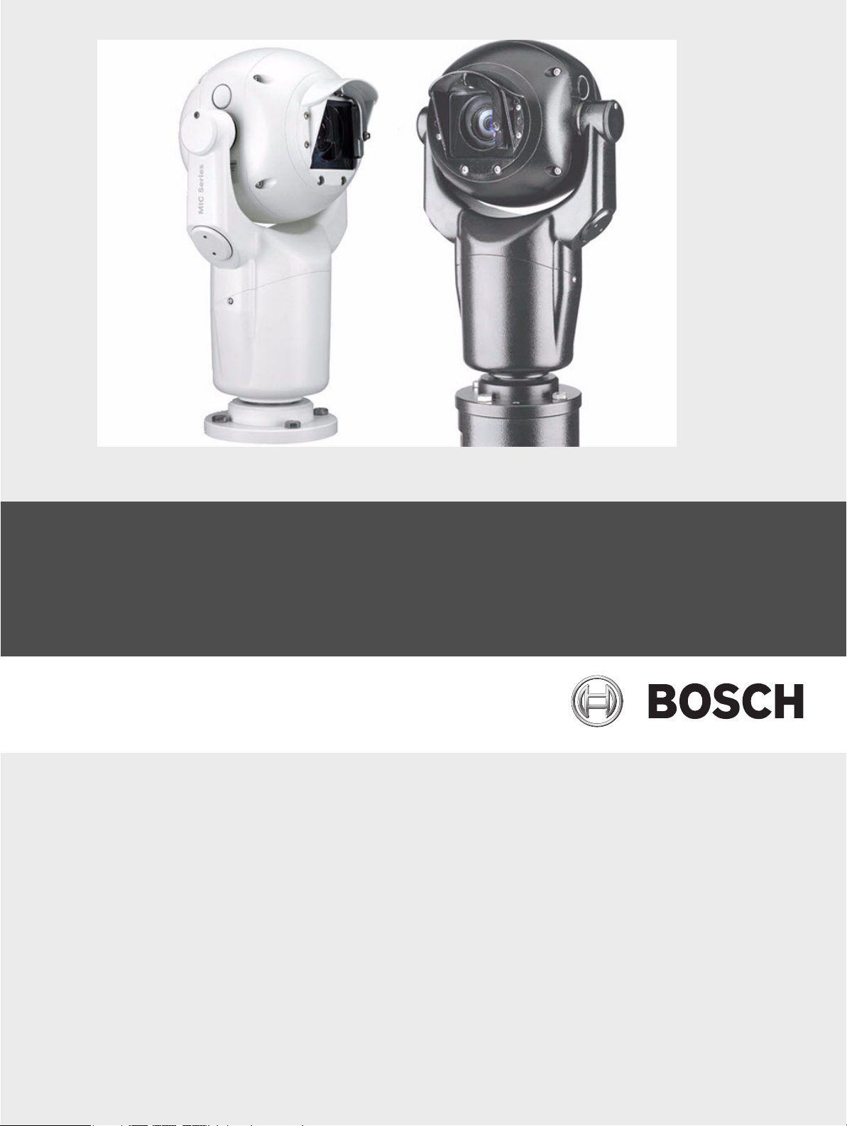
MIC Series 500 Camera
MIC Series 500
en Quick Install Guide
Page 2

Page 3

MIC Series 500 Camera Table of Contents | en 3
Table of Contents
1 MIC 500 Series Camera Quick Start Guide 4
1.1 MIC 500 Series Camera Mounting Instructions 4
1.2 Safety Earthing of the MIC 500 Series Camera 5
1.3 Commissioning the MIC 500 Series Camera 6
Bosch Security Systems, Inc. User’s Manual F.01U.173.601 | 2.0 | 2010.11
Page 4

4 en | MIC 500 Series Camera Quick Start Guide MIC Series 500 Camera
1 MIC 500 Series Camera Quick Start Guide
CAUTION!
To reduce the risk of electrical shock, disconnect power supply before opening the power
supply unit.
Power disconnect: power supply units have power supplied whenever the power cord is
inserted into the power source.
WARNING!
Installation should be carried out by qualified personnel only in accordance with the
applicable local codes.
Bosch Security Systems Inc. accepts no liability for any damages or losses caused due to
incorrect or improper installation.
1.1 MIC 500 Series Camera Mounting Instructions
The upright unit can be mounted with the camera ball up or down.
For inverted units, first remove the four M3 x 6 screws fixing the rain shield to the face of the
camera, reverse the rain shield, reattach it to ensure that the rain shield is oriented correctly,
and then configure the camera for inverted operation. For further details of configuring and
reversing the controls for inverted units using the MIC Series Universal Camera Setup
Software (cam-set) or via the MIC 500 Series camera on-screen menu, please refer to the Help
and Instruction file in cam-set.
The MIC 500 Series camera, when canted, is designed only to be mounted ball up. The tilt
limits for the canted unit prevent it from working properly if mounted ball down. Do not
manually back drive the pan or tilt axis by hand. Back driving may strip teeth off the internal
gears and in so doing will void the warranty.
M8 Stainless steel nuts, bolts, and washers should be used to secure the base to the
mounting surface. Suitable sealant or the Nebar gasket may be used between the camera
base and the mounting surface.
Ensure that the 12-pin connector is located inside the camera base plug and that the lock ring
is tightened. Ensure that the base compartment containing the 12-way connector is moisture
proof. On inverted units, it is very important that the connector area is watertight to prevent
water pooling around the connector.
Figure 1.1 MIC 500 Series camera mounting positions: Inverted, Upright, and Canted
F.01U.173.601 | 2.0 | 2010.11 User’s Manual Bosch Security Systems, Inc.
Page 5

MIC Series 500 Camera MIC 500 Series Camera Quick Start Guide | en 5
The MIC 500 Series camera has a security attachment point for attaching to a safety chain
(not supplied), which in turn should be attached to a secure part of the structure during
installation or removal.
WARNING!
Use caution when installing the MIC 500 Series camera. Follow common sense precautions
such as fitting a safety chain.
1.2 Safety Earthing of the MIC 500 Series Camera
The electronics and housing of the MIC 500 Series camera are electrically isolated; however,
the housing should be safety earthed regardless. This safety earth should be a bonding
connection, such as one of the securing bolts, to the outside case of the camera. The camera
should be earthed at one point only to prevent earth loops and thus hum bars appearing on
the camera picture in the control room.
Shielded Composite Cable Connections
Note: all connections must be made.
Composite Cable Wire Color Function MIC PSU Terminal Block PCB Marking
Red AC supply HD3-1 Power
Green AC supply return HD3-2 Power
White RX + Hd3-3 RxB
Yellow Rx - HD3-4 RxA
Drain Wire Ground HD3-5 GND
Blue Tx - HD3-6 TxA
Violet Tx + HD3-7 TxB
Coax Core Video HD3-8 Video
Coax Screen Video return HD3-9 Vid 0V
Black (optional) Tamper switch HD3-10 Tamp Sw
Orange (optional) Wash drive HD3-11 Wash
Brown Heater+ HD6-1
Gray
1. Please refer to the MIC Series Power Supply Manual for details on connecting MIC 500 Series cameras with
Heater-
heaters and other auxiliary equipment.
1
HD6-2
Mains Power and Video Connections
Mains
Live HD1-1
Neutral HD1-2
Earth Connection Already made
Video
Video BNC CN1 Connection
Core Video to Control Room
Screen Video GND to Control Room
Bosch Security Systems, Inc. User’s Manual F.01U.173.601 | 2.0 | 2010.11
Page 6

6 en | MIC 500 Series Camera Quick Start Guide MIC Series 500 Camera
A standard female BNC connector provides the composite video output from the MIC 500
Series camera.
Telemetry Connections
The MIC 500 Series camera can be daisy-chained in a multi-drop configuration, the last or
furthest camera in the chain should be typically terminated with a 120 Ω resistor placed
across the cameras receiving pair.
Telemetry
Signal Function Telemetry Signal Name HD4 or HD5
RS485+ to camera RxB Pin 1
RS485– to camera RxA Pin 2
0v from control room GND Pin 3
RS485– to control room TxA Pin 4
RS485+ to control room TxB Pin 5
1.3 Commissioning the MIC 500 Series Camera
The MIC 500 Series camera provides twin protocol support with a single software pack.
Switching between the installed protocols is easily done using cam-set or the on screen menu
function. Three protocol packs are available: Forward vision (FV)/ Bosch, FV/Pelco and FV/
VCL.
All MIC 500 Series cameras are supplied set to address 1 and initially loaded with the FV /
Bosch protocol pack. The available protocol packs are provided on the CD and can be loaded
onto the camera using cam-set.
To use the MIC Series Universal Camera Setup software (cam-set), connect the MIC 500
Series camera power supply (HD4 or HD5) to a PC using either the MIC-USB485CVTR, an
RS485 to USB signal converter, or for older PCs with a serial port, a suitable RS232 to RS485
converter can be used. Please refer to the Help and Instruction file in cam-set for further
details.
F.01U.173.601 | 2.0 | 2010.11 User’s Manual Bosch Security Systems, Inc.
Page 7

Page 8

Bosch Security Systems, Inc.
Robert-Koch-Straße 100
D-85521 Ottobrunn
Germany
Phone +49 89 6290-0
Fax +49 89 6290-1020
www.boschsecurity.com
© Bosch Security Systems, Inc., 2009
 Loading...