

Bosch Greenstar ZWBR 7-25 A23, 47 311 44, Greenstar ZWBR 11-25 A31, 47 311 45 Installation And Servicing Instructions
GREENSTAR
WALL MOUNTED CONDENSING BOILER FOR CENTRAL HEATING
AND MAINS FED DOMESTIC HOT WATER
INSTALLATION AND
SERVICING INSTRUCTIONS
GC NUMBERS
Greenstar ZWBR 7-25 A23 (N.G.) 47 311 44
Greenstar ZWBR 11-25 A31 (L.P.G.) 47 311 45
THIS APPLIANCE IS FOR USE ON SEALED PRIMARY SYSTEMS ONLY
IMPORTANT: THESE INSTRUCTIONS APPLY IN THE UK ONLY
THESE INSTRUCTIONS ARE TO BE LEFT WITH THE USER OR AT THE GAS METER
This appliance must be installed by a competent person in accordance
with the Gas Safety (Installation and Use) Regulations 1998
Cat II appliance
2H 3P

2
10. Domestic Hot Water.................................................... Page 8
11. Electrical........................................................................ Page 8
12. Installation .................................................................... Page 10
13. Commissioning ............................................................ Page 15
14. Instructions to the User .............................................. Page 21
15. Inspection and Servicing ............................................ Page 21
16. Replacement of Parts.................................................. Page 24
17. Short Parts List ............................................................ Page 28
18. Fault Finding .............................................................. Page 29
1. Installation Regulations.............................................. Page 2
2. Introduction.................................................................. Page 2
3. Technical Data .............................................................. Page 3
4. Siting the Appliance .................................................... Page 5
5. Flue Systems ................................................................ Page 5
6. Siting the Flue Terminal .............................................. Page 6
7. Gas Supply.................................................................... Page 6
8. Air Supply .................................................................... Page 7
9. Sealed System .............................................................. Page 7
Contents
Gas Safety (Installation & Use) Regulations 1998: All gas
appliances must be installed by a competent person. Failure to
install correctly could lead to prosecution.
The manufacturers notes must not be taken, in any way, as
overriding statutory obligations.
The appliance must be installed in accordance with the current
IEE Wiring Regulations, local Building Regulations, Building
Standards (Scotland) (Consolidation), bye-laws of the local Water
Company, Health and Safety Document 635 (Electricity at Work
Regulations 1989) and any other local requirements.
Product Liability regulations indicate that, in certain
circumstances, the installer can be held responsible, not only for
mistakes on his part but also for damage resulting from the use
of faulty materials. We advise the installer to avoid any risk by
using only quality approved branded fittings.
The relevant British Standards should be followed i.e.
BS 6798 Specification for the installation of gas fired hot water
boilers of rated input not exceeding 60kW
BS 5449 Central Heating for Domestic Premises
BS 5546 Installation of gas hot water supplies for domestic
purposes
BS 5440:1 Flues and ventilation for gas appliances of rated input
not exceeding 60kW: Flues
BS 5440:2 Flues and ventilation for gas appliances of rated input
not exceeding 60kW: Air Supply
BS 6891 Installation of low pressure gas pipework
installations up to 28mm (R1).
BS 7074:1 Code of practice for domestic heating and hot water
supply.
These instructions must be followed.
The appliance output of 25.3kW in the condensing mode is
available for the heating system and up to 23.5kW for the
domestic hot water with the domestic hot water having the
priority. An automatic hot water pre-heat facility is available to
give an almost instant supply of hot water at the tap or shower.
The appliance is supplied for use on a sealed system only and is
not suitable for external installation. It must be connected to a
governed metered gas supply. It is dispatched suitable for use on
Natural Gas.
It is a room sealed appliance and does not require a separate
combustion air supply – because of the low casing losses
ventilation are not required when the appliance is installed in a
cupboard or compartment.
Do not block the specified space left for servicing.
An electrical supply failure will stop the appliance. Normal
operation will resume upon the restoration of the supply.
A standard 100mm flue system is available for horizontal flues
upto 2m.
Multi-directional flue systems are available up to 10m
horizontally and 8m vertically. A twin-pipe system is available.
An integral facia display shows the central heating flow
temperature or a fault condition of the appliance.
Comprehensive safety features are standard as is an automatic
ignition system. The use of a pre-mixed burner gives a very low
NOxdischarge level.
Do not run the appliance in the waterless condition.
The condensing mode gives very high efficiency figures which
can be utilised fully by sizing the system to match the
condensing parameters i.e. low temperature radiators. However
the appliance will operate at normal flow temperatures when
required to do so and still maintain high system efficiencies.
To ensure that the appliance gives the best performance possible
it is recommended that an outside temperature compensator
(Junkers TA211E) and a twin-channel digital programmer (Junkers
EU2D) are fitted.
Full installation and operating instructions are packed with the
controls.
Check that no dirt is left in either the gas or water pipework as
this could damage the appliance. Thoroughly flush the heating
system and mains water supply in accordance with the
recommendations of BS 7593:1992.
The heat exchanger is manufactured from aluminium and only
compatible flushing agents shall be used.
A link is provided to allow flushing of the system before the
appliance is hung on the mounting manifold.
Purge the gas supply before finally connecting the appliance.
To ensure that the installation will perform to the highest
standards, the system and components should conform to any
other relevant British Standards in addition to those mentioned
in the instructions.
The boiler, when in use, will operate at high efficiency emitting a
white plume of condensation from the flue terminal.
Positions that might cause a nuisance should be avoided.
A condensate drain and syphon is provided on the appliance.
Take special note of the requirements for the drainage of
condensate.
The advice and instructions in this document covers, as far as
possible, the forseeable situations which may arise. Contact
Worcester Heat Systems for advice on specific installations.
LPG Installation
The appliance shall not be installed in a room or internal space
below ground level when it is intended to be used with LPG. This
does not preclude the installation into rooms which are
basements with respect to one side of the building but open to
the ground on the opposite side.
Asbestos or asbestos based products are not used on this
appliance nor in the manufacturing process.
2. Introduction
1. Installation Regulations
3
APPLIANCE DIMENSIONS, WEIGHT & CONNECTIONS
Height mm
Casing 850
Overall 1065-1165
Width mm 512
Depth mm 390
Weight kg
Installation 74
Full 90
Inc. Packing 76
Central Heating Flow/Return 22mm comp.
Domestic Hot Water Inlet/Flow 15mm comp.
Gas Inlet R
3
⁄4
Table 2
NOMINAL BOILER RATINGS
SETTING
FLOW RETURN OUTPUT INPUT GAS RATE-NG
TEMPERATURE °C TEMPERATURE °C kW kW (Net) m
3
/h
MAXIMUM
80 60 23.0 24.0 2.54
50 30 25.3 24.0 2.54
MINIMUM
80 60 6.7 7.2 0.762
50 30 7.7 7.2 0.762
Table 1
3. Technical Data
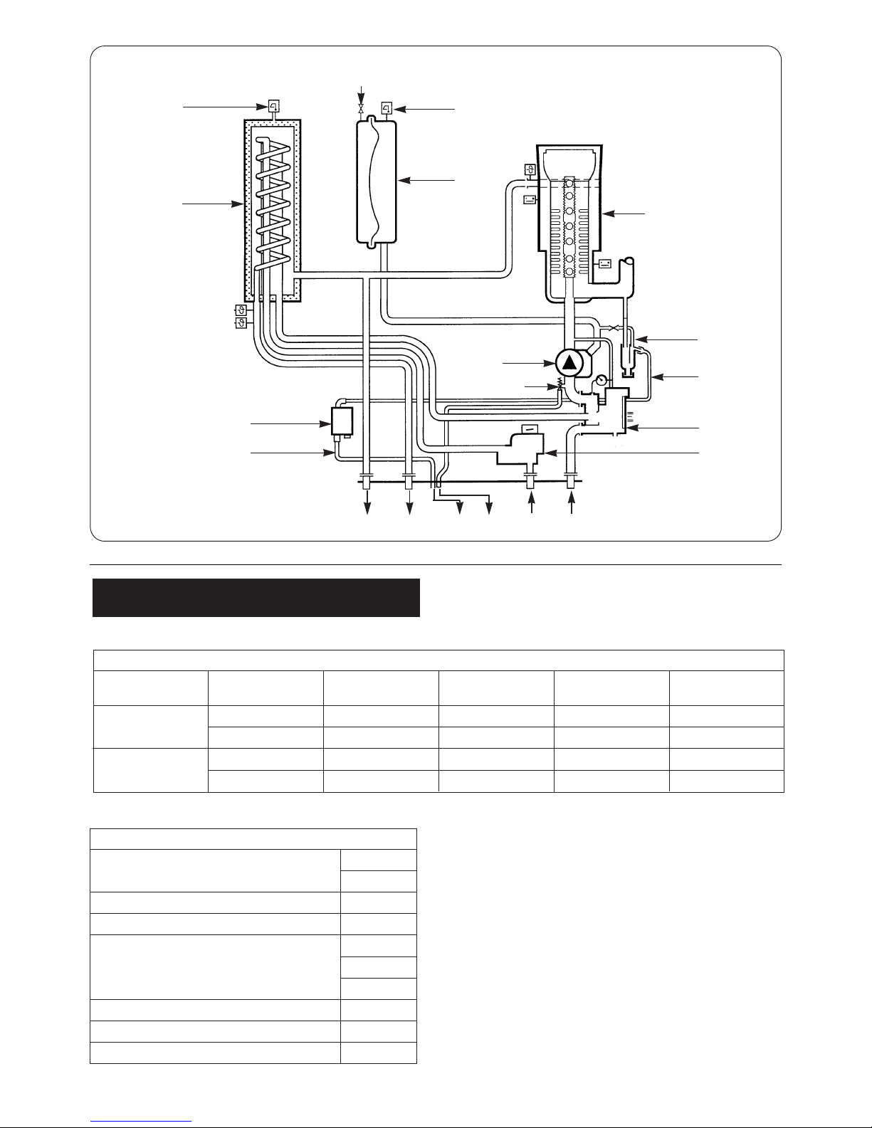
Fig. 1. Appliance water flow diagram.
Automatic
Air
Vent
Water
to
Water
Heat
Exchanger
Automatic
Air
Vent
Charging Point
Expansion
Vessel
Heat
Exchanger
Condensate
Trap
Drain
Diverter
Valve
Flow
Switch
Siphon
Drain
Pump
Pressure Relief Valve
Domestic Hot
Water Out
CH
Flow
Condensate & Relief
Valve Drain
Domestic
Cold Supply
CH
Return
NOTE: Net Input = Gross Input x 0.901 - Natural Gas
4
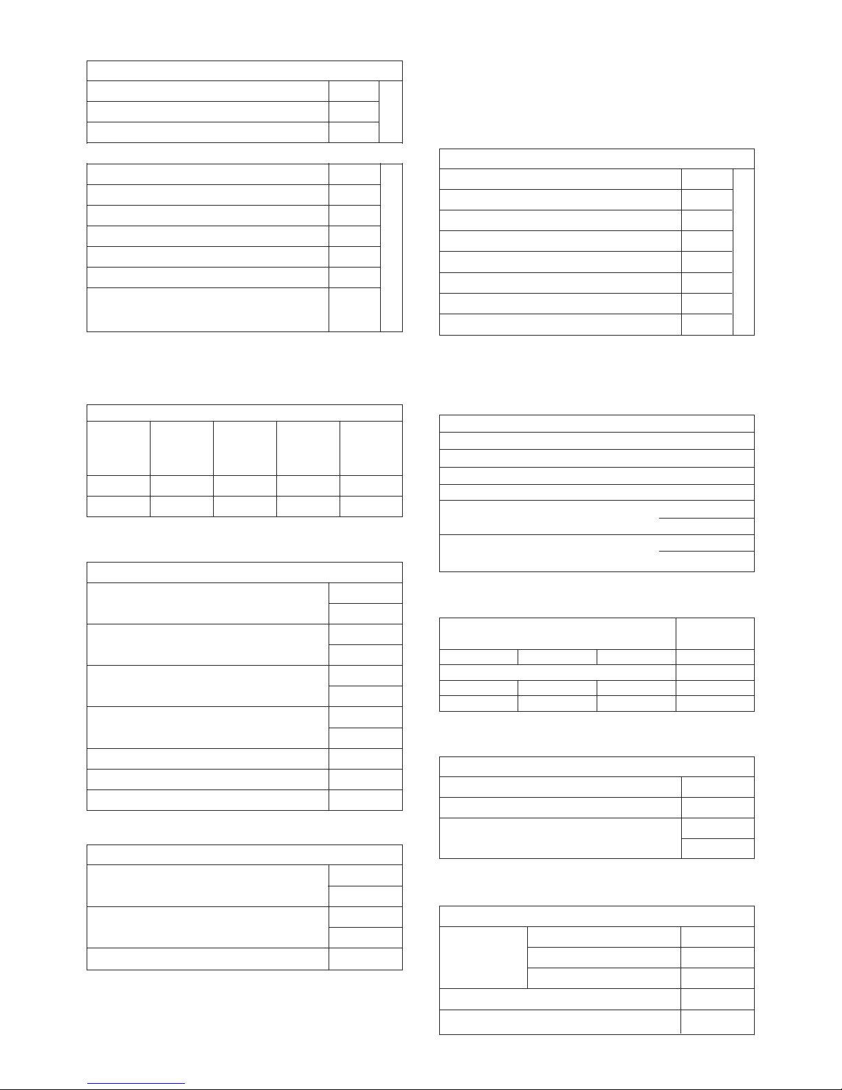
FLUE GAS AND CONDENSATE DATA
Flue Gas, Mass Flow kg/h Max. 42.8
Min. 12.6
Flue Gas Temperature °C Max. 71
Flow 80°C Return 60°C Min. 62
Flue Gas Temperature °C Max. 36
Flow 50°C Return 30°C Min. 32
Condensate Volume l/h Max. 2.2
Return 30°C Min. 0.94
Condensate pH Nominal 4.1
CO
2
% Max. 8.4-9.0
NOx Class 5
Table 5
PUMP HEAD & PRIMARY FLOW
BOILER AVAILABLE
NOMINAL TEMPERATURE BOILER
OUTPUT HEAD
SYSTEM RISE ACROSS FLOW
kW m
FLOW RATE THE SYSTEM TEMPERATURE
l/min °C °C
23.5 2 20 20 80
25.3 2 16-18 20 50
Table 4
CENTRAL HEATING
Heat Output 80/60°C kW Max. 23.5
Min. 6.7
Heat Output 50/30°C kW Max. 25.3
Min. 7.7
SEDBUK No. 90.8
Table 6
Note: To gain maximum benefit from the performance of the appliance the
radiators must be sized according to the Flow/Return temperatures.
Total length of gas supply pipe Pipe diameter
(metres) (mm)
36 9
Gas Discharge Rate (m3/h)
8.7 5.8 4.6 22
18.0 12.0 9.4 28
Table 8
EXPANSION VESSEL PRESSURE & SYSTEM CAPACITY
Expansion Vessel litres 10
Expansion Vessel Charge Pressure bar 0.75
System Capacity 1 bar litres 82
Ref. BS 7074:1 1.5 bar litres 46
Table 9.
DOMESTIC WATER PERFORMANCE
Domestic
Temperature Rise 30°C 11.1
Water Flow Temperature Rise 35°C 9.5
Rate l/min
Temperature Rise 40°C 8.4
Maximum Mains Pressure bar 8.0
Minimum Mains Pressure bar 0.2
Table 10
Factory Setting
Pump Control Mode 2
Anti-Cycle Time min 3
Maximum CH Temperature °C 80
ThermostatTemperature Differential °C 8
Maximum CH Output kw 23.0 standard
25.3 condensing
Minimum CH Output kw 6.7 standard
7.7 condensing
Table 7
HORIZONTAL 100mm
Overall Diameter of Duct mm 100
Flue Terminal/Duct Assembly Length mm 600
Extension Duct Length mm 503
Overall Diameter of Duct mm 125
Flue Terminal/Duct Assembly mm 550
Extension Duct Length – Fixed mm 200
Extension Duct Length – Fixed mm 450
Extension Duct Length – Fixed mm 950
Extension Duct Length – Fixed mm 1950
Extension Duct Length – Telescopic mm 265-375
Extension Duct Length –
Adjustable
mm 200
Table 3
Max. 2m
Max. 8m
(Cut to
length)
Note: A twin pipe horizontal system is available for lengths up to 10m.
ALTERNATIVE HORIZONTAL 125mm FLUE SYSTEM
VERTICAL 125mm FLUE SYSTEM
Overall Diameter of Duct mm 125
Flue Terminal/Duct Assembly Length mm 1360
Extension Duct Length mm 200
Extension Duct Length – Fixed mm 450
Extension Duct Length – Fixed mm 950
Extension Duct Length – Fixed mm 1950
Extension Duct Length – Telescopic mm 265-375
Extension Duct Length –
Adjustable
mm 450
Max. 8m
Elbow – 90° Bend – 45°
Equivalent length 1m Equivalent length 0.5m
A vertical 100mm flue system will be available
(Cut to
length)
The appliance is not suitable for external installation.
The appliance may be installed in any room subject to the
requirements of the IEE Wiring Regulations or the electrical
provisions of the Building Regulations applicable in Scotland
relevant to appliances fitted in rooms containing baths or
showers. It must not be possible for anyone using the bath or
shower to touch any control using mains electricity.
No special wall protection is required. Ensure that the wall can
support the appliance. Refer to the IGE publication “Guide for
Gas Installations in Timber Framed Housing” where appropriate,
IGE/UP/7:1998.
The specified clearances must be available for installation and
servicing. Refer to Fig. 2 and 3.
The appliance can be installed in a cupboard/compartment to
be used for airing clothes providing that the requirements of
BS6798 and BS45440:2 are followed. The low casing losses from
the appliance eliminate the need for ventilation openings in the
compartment.
The airing space must be separated from the boiler space by a
perforated non-combustible partition. Expanded metal or rigid
wire mesh is acceptable provided that the major dimension is
less than 13mm.
The clearance between the front of the appliance and the
cupboard or compartment door should not be less than 75mm.
The pipe connection positions on the manifold are shown in Fig.4
and on the wall template allowing the system to be pre-piped
and flushed before the appliance is fitted.
Always consider the possibility that the pipes may need to be
separated from the appliance after installation.
The only flue systems that may be used are those sold by
Worcester Heat Systems.
The flue system must be installed in accordance with the
requirements of BS5440:1.
Standard 100mm flue system.
The standard concentric flue system provides for a horizontal
length of upto 2m. Full instructions for fitting this flue are in
Section 12 Installation.
Alternative 125mm diameter flue systems.
Systems are available to give a maximum horizontal length of
10m (this system requires a greater clearance above the
appliance. Refer to Fig.3.) A vertical flue system upto a height of
8 metres is available. A twin-pipe system is available for
extended lengths or difficult situations.
NOTE: A 100mm vertical flue systems will be available in the
future.
Installation instructions for the alternative flue systems are sent
with the appropriate flue kit.
45° and 90° bends can be used with a corresponding reduction
in flue length of 1m for each 90° bend and 0.5m for each 45°
bend used.
IMPORTANT: The horizontal flue system fitted to a condensing
boiler must incline towards the appliance at an angle of 2
1
/2°
(44mm per metre length) to prevent condensate dripping
from the flue terminal. This means that the clearance above
the appliance must be increased to match the duct length.
5. Flue Systems
4. Siting the Appliance
5
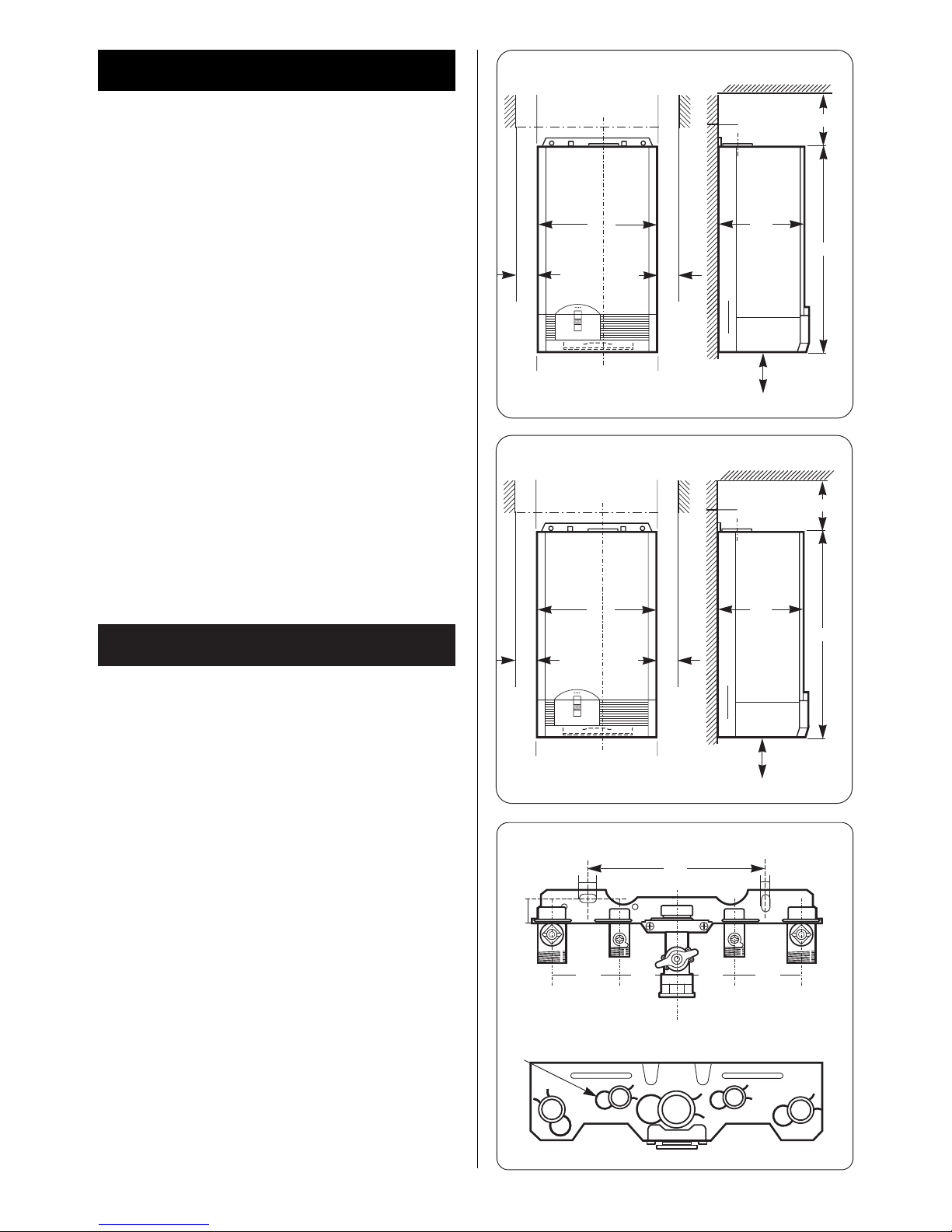
Fig. 2. Casing dimensions and clearances.
512
100
215
850
250
STANDARD CONCENTRIC HORIZONTAL FLUE SYSTEM
100
Fig. 4. Manifold connections.
Central
heating
flow
Valve
clips
Wall mounting manifold plate
Domestic
hot
water
Cold
water
inlet
Central
heating
return
Gas
30
20
10
390
Fig.3. Casing dimensions and clearances.
512
100
315
850
250
ALTERNATIVE CONCENTRIC HORIZONTAL FLUE SYSTEM
100
390
▲
▲
▲
▲
200
▲
▲
6565 65 65
▲
▲
▲
▲
▲
▲
▲
▲
▼
▼
115
▼
▼
115

The flue must be installed in accordance with BS 5440:1 and the
Building Regulations.
The terminal must be positioned so that it does not cause an
obstruction or the combustion products a nuisance. See Fig.5.
The terminal will, at times, give out a plume of water vapour and
consideration must be given to this when choosing a terminal
position. Keep clear of security lighting, activated by passive
infra-red sensing heads.
If the terminal is within 1m of a plastic or painted gutter or
within 500mm of painted eaves then an aluminium shield at
least 750mm long should be fitted to the underside of the gutter
or painted surface.
If the terminal is less than 2m above a surface to which people
have access then a guard must be fitted. The guard must be
evenly spaced about the terminal with a space of 50mm in each
direction and fixed with plated screws.
A guard, can be obtained from Tower Flue Components, Vale
Rise, Tonbridge TN9 1TB.
The appliance requires 2.54m
3
/h of natural gas. The gas meter
and supply pipes must be capable of supplying this quantity of
gas in addition to the demand from any other appliances being
served.
The meter governor should deliver a dynamic pressure of 20
mbar at the appliance, equivalent to a pressure of about 18.5 –
19mbar at the gas valve inlet.
7. Gas Supply
6. Siting the Flue Terminal
L
L
K
K
F
F
G
A
M
EJF
HI
D
G
A
B,C
6
Fig. 5. Acceptable terminal positions.
TERMINAL POSITION MIN. DISTANCE
A– Directly below an openable window or
other opening e.g. air brick. 300 mm (12 in.)
B– Below gutters, soil pipes or drain pipes. 75 mm (3 in.)
C– Below eaves. 200 mm (8 in.)
D– Below balconies or car port roof. 200 mm (8 in.)
E– From vertical drain pipes and soil pipes. 75 mm (3 in.)
F– From internal or external corners. 300 mm (12 in.)
G– Above ground, roof or balcony level. 300 mm (12 in.)
H– From a surface facing a terminal. 600 mm (24 in.)
I– From a terminal facing a terminal 1200 mm (47 in.)
J– From an opening in a car port (e.g. door
window) into dwelling. 1200 mm (47 in.)
K– Vertically from a terminal on the same
wall. 1500 mm (59 in.)
L– Horizontally from a terminal on the same
wall. 300 mm (12 in.)
M– From door, window or air vent (achieve
where possible). 150 mm (6 in.)
Where LPG is used, following conversion from Natural Gas, then
a dynamic inlet pressure of 37mbar at the inlet to the appliance
is required. Equivalent to a pressure of about 34.5 – 35mbar at
the gas valve inlet.
The complete installation, including the meter, must be tested
for soundness and purged. See BS 6891.
A separate air supply for combustion is not required.
If the appliance is in a cupboard or compartment then, because
of the low casing losses, it is not necessary to have additional
ventilation for the boiler.
The specified clearances around the appliance must be
maintained to allow the free movement of the air. Refer to
Fig.2,3.
Note: In order to prevent corrosion the air for combustion must not
contain corrosive substances such as solvents, paints, adhesives,
household cleaners etc. The combustion air should be dust free to
reduce the risk of the pre-mix burner becoming blocked.
The appliance must not be operated without the system being
full of water, properly vented and pressurised.
The expansion vessel has a volume of 10 litres and is charged to
a pressure of 0.75 bar.
The water capacity of the system is shown in Table 9. If a greater
capacity is required then an additional expansion vessel must be
fitted into the system return as close to the appliance as possible.
The system pressure can be set up to a maximum of 1.5 bar with
1 bar being the normal setting.
If the system pressure is greater than 2.5bar when the appliance
is operating at maximum temperature then an additional
expansion vessel must be fitted into the system return as close
to the appliance as possible.
The filling point must be at low level and arranged as shown in
Figs. 6 and 7
The pressure relief valve is set to operate at 3 bar.
There must be no connection to the mains without the approval
of the local water company. All connections in the system must
be capable of withstanding a pressure of up to 3 bar and the
radiator valves conform to the requirements of BS 2767:10.
If Thermostatic Radiator Valves are fitted then it is recommended
that one radiator is left open.
Repeated venting probably indicates a leak and this must be
rectified to ensure the proper operation of the appliance.
No galvanised radiators or pipes must be used.
If any system water treatment is required then only products
suitable for use with Aluminium shall be used i.e FernoxCopal or Sentinal X100, in accordance with the
manufacturers instructions. The use of any other substances
will invalidate the guarantee. The pH value of the system
water must be less than 8 or the appliance guarantee will be
invalidated.
A drain cock to BS2879 must be fitted to the lowest point of the
system.
IMPORTANT: Check that no dirt is left in the water pipework
as this could damage the appliance. Thoroughly flush the
heating system and the mains water supply before fitting the
applianceto the wall in accordance with the
recommendations of BS7593:1992.
9. Sealed Systems
8. Air Supply
7
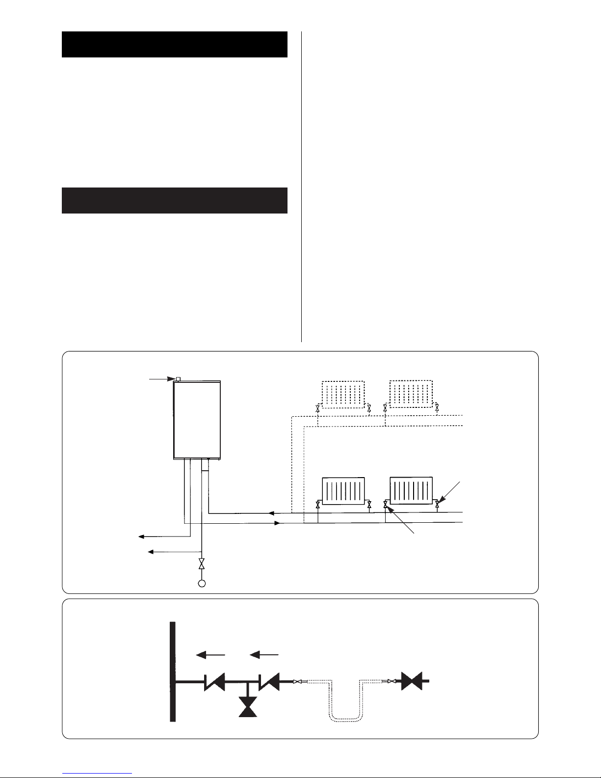
Fig. 7. Sealed primary water system – filling method.
Fig. 6. Sealed primary water system.
Automaticl air vent
Domestic
hot water
Domestic
hot water
Central heating flow
Radiator
valve
Lockshield
valve
Central heating return
A drain cock should be fitted at
the lowest point of the heating
circuit and the appliance
Water
main
BS stop valve.
Fixed spindle type
Heating
return
Non-return
valve
Non-return
valve
Hose
union
Hose
union
Test
cock
Temporary hose
Test
cock
APPLIANCE
Refer to Fig.1
Appliance
water flow
diagram
WRC approved
filling loop

Any regulations specified by the local water company must be
observed.
The final 600mm of the mains cold water connection to the
appliance should be made in copper tube only.
The appliance is suitable for a mains supply having a maximum
pressure of 8 bar. A pressure reducing valve must be fitted, if
necessary.
The hot water outlet temperature is set to be capable of
achieving a maximum of 55°C. When operating normally the
boiler operates occasionally to maintain an 8 litre heat store at
this temperature ensuring that hot water is available at the tap
or shower almost immediately it is required. The maximum
temperature and the frequency of the recharge of the heat store
may be reset.
The maximum water flow rate is factory set at 9.5l/min to give
temperature rise of 35°C. If a higher rise is required then the flow
must be reduced at the tap and the discharge temperature will
rise up to the maximum set figure.
The temperature rise, upto the maximum set by the user, is
automatically maintained by the modulation of the heat input.
In winter, when the mains temperature is very low, the water
flow, adjusted at the tap or shower, should be reduced to
maintain the required delivery temperature.
It is suggested that long pipe runs to taps or showers be
insulated to prevent the rapid cooling of the water.
All types of single lever mixer taps and thermostatic mixer units
suitable for a mains pressure of up to 8 bar can be used.
The head of a loose-head shower must not be allowed to fall
within 25mm of the top the bath to prevent the risk of water
being drawn back into the mains. Alternatively the shower must
be fitted with an anti-syphonage device at the point of the
flexible hose connections.
Over-rim bidets may be connected to the appliance provided
that it is in accordance with the requirements of the local water
company. The outlet(s) should be shrouded and unable to have
any temporary hand held spray attached. No anti-syphonage
arrangements are necessary.
In exceptionally hard water areas a device to prevent scale
formation may be fitted or, alternatively, the maximum
temperature reset to about 45°C which may reduce the risk of
scale formation. The installation of a scale inhibitor assembly
should be in accordance with the requirements of the local water
company. Artificially softened water must not be used. An
isolating valve should be fitted to allow for servicing.
Devices capable of preventing the flow of expansion water must
not be fitted unless separate arrangements have been made.
A Zilmet Z160 expansion vessel is the preferred type. A thread
sealant compatible with potable water must be used.
Supply: 230V ~ 50Hz 140 watts. External fuse 3A. Protection
IPX4C.
Mains cable: PVC insulated 0.75mm
2
(24 x 0.20mm) to
BS 6500–Table 6. Temperature rated 100°C.
It must be possible to isolate the appliance
The appliance must be earthed.
The appliance must be connected to the mains through a 6A
double pole isolator with a contact separation 3mm in all poles
and supplying the appliance and controls only. The wiring must
comply with the current requirements of the IEE Wiring
Regulations and any local regulations which apply.
To gain access to the mains connection remove the drop down
facia cover. The drop down cover is removed by lowering it to the
horizontal position and pushing firmly upwards at the rear of
the supports to release the cover. Lift cover from the appliance.
Remove the facia connection cover. Refer to Fig.
After installation (or in the event of an electrical fault) the electrical
system shall be checked for short circuits, fuse failure, incorrect
polarity of connections, earth continuity and resistance to earth.
11. Electrical10. Domestic Hot Water
8
9
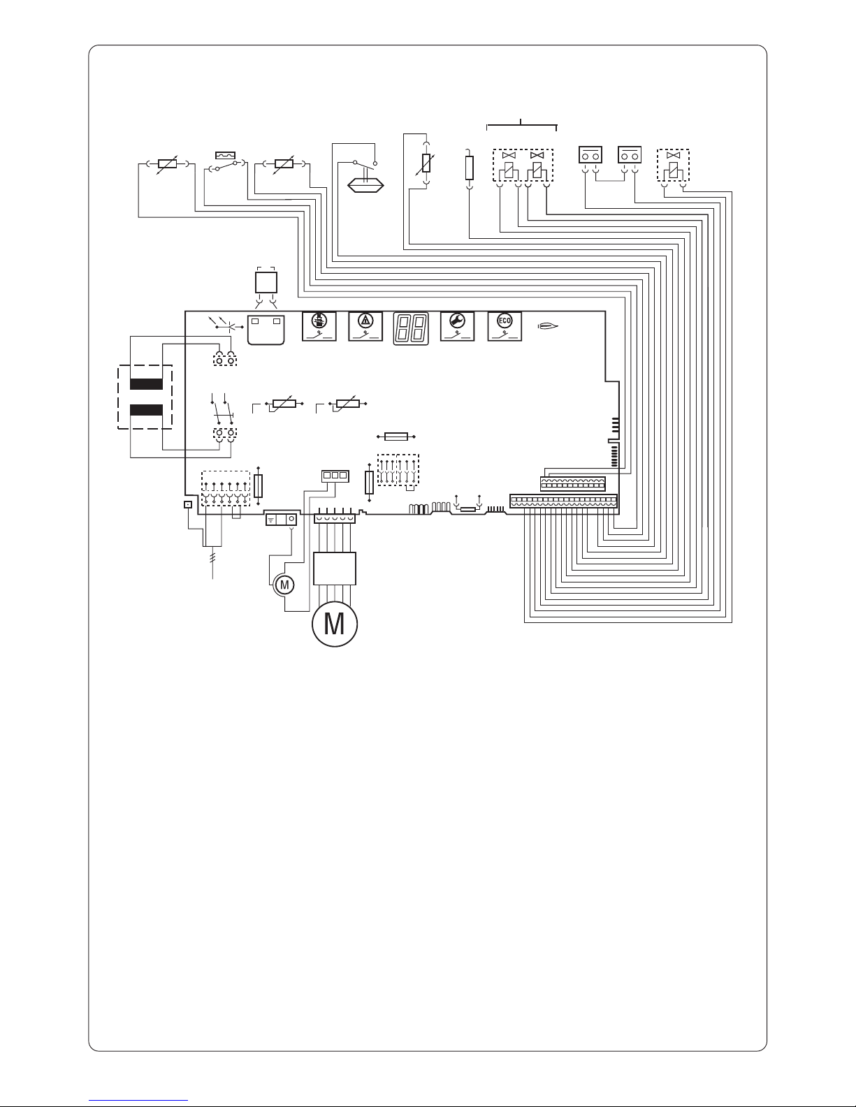
Fig. 8. Pictorial wiring diagram.
o - orange g - green bl - black r - red p - purple
20
21
22
23
24
25
27 28
26
29 30
31
13
11
12
14
15
16
17
18
19
8
9
10
3
4
7
6
5
2
Mains
Input
328
Fan
Module
Pump
Fan
1
1 Fuse 2.5A, 230V AC
2 Fuse 0.5A
3 Fuse 1.6A
4 Control unit connection
5 Key Plug
6 TA 211E control connection
7 Time switch connection
8 On/off switch
9 CH temperature
10 DHW temperature control
11 Power on indicator
12 Ignition transformer
13 Ignition electrodes
14 Setting button
15 Reset button
16 Display
17 Service button
18 ECO button
19 Burner indicator
20 DHW temperature sensor
21 Water pressure switch (flow switch)
22 DHW inlet sensor
23 Air flow switch
24 CH flow temperature sensor
25 Flame sense electrode
26 Gas valve
27 Gas solenoid valve No.1
28 Gas solenoid valve No.2
29 Flue gas temperature limiter
30 Overheat temperature limiter
31 Diverter valve solenoid
25V
230V
AC
o
o
g
g
g
g
bl
bl
o
o
bl
bl bl
bl
bl
r
r
r
p
p

The standard 100mm diameter horizontal flue system is suitable
for lengths upto 2m.
Flues upto 670mm do not require an extension duct assembly.
Flues between 670mm 1620mm require 1 extension duct
assembly.
Flues between 1620mm and 2000mm require 2 extension duct
assemblies.
NOTE: Flue lengths between 670mm and 730mm cannot be
accomodated.
Refer to Fig.F1,F2 and F3.
Standard system comprise:
Flue turret
_
Flue turret clamp _ Terminal assembly _ Wall sealing
plates.
Extension kit comprises:
Air duct
_
Flue duct _ Duct clamp.
Refer to Fig.F4.
10
12. Installation
Fig. F1. Standard Flue.
Flue
Turret
Flue
Sample
Point
Clamp
No
Clamp
Maximum 670mm
Terminal
Assembly
Outer
Wall
Fig. F2. Flue with One Extension .
Maximum 1620mm
Flue
Turret
Flue
Sample
Point
Clamp
No
Clamp
Clamp
Terminal
Assembly
Outer
Wall
Extension
Duct
Fig. F3. Flue with Two Extensions .
Flue
Turret
Flue
Sample
Point
Clamp
No
Clamp
Maximum 2000mm
Clamp
Extension
Duct
Clamp
Extension
Duct
Terminal
Assembly
Outer
Wall
 Loading...