


ACU 201-07
Table of contents
 Loading...
BONFIGLIOLI ACU 201-07, ACU 201-13, ACU 201-09, ACU 201-11, ACU 201-03 Operating Instructions Manual
...
ACTIVE CUBE
Operating Instructions
Frequency inverter 230 V / 400 V
0.25 kW ... 132 kW


TABLE OF CONTENTS
1 General information about the documentation ........................................................... 10
1.1 Instruction manuals .................................................................................. 10
1.2 This document........................................................................................... 12
1.3 Warranty and liability ............................................................................... 12
1.4 Obligation ................................................................................................. 13
1.5 Copyright .................................................................................................. 13
1.6 Storage ...................................................................................................... 13
2 General safety instructions and information on use .................................................... 14
2.1 Terminology .............................................................................................. 14
2.2 Designated use ......................................................................................... 15
2.3 Misuse ....................................................................................................... 15
2.3.1 Explosion protection ........................................................................................ 15
2.4 Residual risks ............................................................................................ 16
2.5 Safety and warning signs at frequency inverter ....................................... 16
2.6 Warning information and symbols used in the user manual .................... 17
2.6.1 Hazard classes ................................................................................................ 17
2.6.2 Hazard symbols............................................................................................... 17
2.6.3 Prohibition signs .............................................................................................. 17
2.6.4 Personal safety equipment ............................................................................... 18
2.6.5 Recycling ........................................................................................................ 18
2.6.6 Grounding symbol ........................................................................................... 18
2.6.7 ESD symbol .................................................................................................... 18
2.6.8 Information signs ............................................................................................ 18
2.7 Directives and guidelines to be adhered to by the operator .................... 19
2.8 Operator's general plant documentation .................................................. 19
2.9 Operator's/operating staff's responsibilities ............................................ 19
2.9.1 Selection and qualification of staff .................................................................... 19
2.9.2 General work safety ........................................................................................ 19
2.10 Organizational measures .......................................................................... 20
2.10.1 General .......................................................................................................... 20
2.10.2 Use in combination with third-party products ..................................................... 20
2.10.3 Transport and Storage ..................................................................................... 20
2.10.4 Handling and installation .................................................................................. 20
2.10.5 Electrical connections ...................................................................................... 20
2.10.5.1 The five safety rules ........................................................................................ 21
2.10.6 Safe operation ................................................................................................ 21
2.10.7 Maintenance and service/troubleshooting .......................................................... 22
2.10.8 Final decommissioning ..................................................................................... 22
2.11 Safety Instructions on Function „Safe Torque Off“ (STO) ........................ 23
3 Scope of Supply ............................................................................................................ 25
3.1 ACU 201 (up to 3.0 kW) and 401 (up to 4.0 kW) ...................................... 25
3.2 ACU 201 (4.0 to 9.2 kW) and 401 (5.5 to 15.0 kW) .................................. 26
3.3 ACU 401 (18.5 to 30.0 kW) ....................................................................... 27
3.4 ACU 401 (37.0 to 65.0 kW) ....................................................................... 28
3.5 ACU 401 (75.0 to 132.0 kW) ..................................................................... 29
06/13 Operating Instructions ACU 3

4 Technical Data .............................................................................................................. 30
4.1 General technical data .............................................................................. 30
4.2 Technical Data – Control Electronic Equipment ....................................... 31
4.3 ACU 201 (0.25 to 1.1 kW, 230 V) .............................................................. 32
4.4 ACU 201 (1.5 to 3.0 kW, 230 V) ................................................................ 33
4.5 ACU 201 (4.0 to 9.2 kW, 230 V) ................................................................ 34
4.6 ACU 401 (0.25 to 1.5 kW, 400 V) .............................................................. 35
4.7 ACU 401 (1.85 to 4.0 kW, 400 V) .............................................................. 36
4.8 ACU 401 (5.5 to 15.0 kW, 400 V) .............................................................. 37
4.9 ACU 401 (18.5 to 30.0 kW, 400 V) ............................................................ 38
4.10 ACU 401 (37.0 to 65.0 kW, 400 V) ............................................................ 39
4.11 ACU 401 (75.0 to 132.0 kW, 400 V) .......................................................... 40
4.12 Operation diagrams .................................................................................. 41
5 Mechanical Installation ................................................................................................ 42
5.1 ACU 201 (up to 3.0 kW) and 401 (up to 4.0 KW) ..................................... 43
5.2 ACU 201 (4.0 to 9.2 kW) and 401 (5.5 to 15.0 kW) .................................. 44
5.3 ACU 401 (18.5 to 30.0 kW) ....................................................................... 45
5.4 ACU 401 (37.0 to 65.0 kW) ....................................................................... 46
5.5 ACU 401 (75.0 to 132.0 kW) ..................................................................... 47
6 Electrical Installation ................................................................................................... 48
6.1 EMC Information ....................................................................................... 50
6.2 Block diagram ........................................................................................... 52
6.3 Optional Components ............................................................................... 53
6.4 Connection of Unit .................................................................................... 54
6.4.1 Dimensioning of conductor cross-section ........................................................... 54
6.4.1.1 Typical cross-sections ...................................................................................... 54
6.4.2 Mains Connection ............................................................................................ 56
6.4.3 Motor Connection ............................................................................................ 56
6.4.3.1 Length of motor cables, without filter ................................................................ 57
6.4.3.2 Motor cable length, with output filter dU/dt ....................................................... 57
6.4.3.3 Motor cable length, with sinus filter .................................................................. 57
6.4.3.4 Group drive .................................................................................................... 58
6.4.3.5 Speed sensor connection ................................................................................. 58
6.4.4 Connection of a Brake Resistor ......................................................................... 59
6.5 Connection of types .................................................................................. 60
6.5.1 ACU 201 (up to 3.0 kW) and 401 (up to 4.0 kW) ................................................ 60
6.5.2 ACU 201 (4.0 to 9.2 kW) and 401 (5.5 to 15.0 kW) ............................................ 62
6.5.3 ACU 401 (18.5 to 30.0 kW) .............................................................................. 64
6.5.4 ACU 401 (37.0 to 65.0 kW) .............................................................................. 66
6.5.5 ACU 401 (75.0 to 132.0 kW) ............................................................................ 68
6.6 Control Terminals...................................................................................... 70
6.6.1 External DC 24 V power supply ......................................................................... 72
6.6.2 Relay Output .................................................................................................. 72
6.6.3 Motor Thermo-Contact ..................................................................................... 73
6.6.4 Control terminals – Connection diagrams of configurations ................................. 73
6.7 Configurations overview ........................................................................... 74
6.7.1 Configuration 110 – Sensorless Control ............................................................. 75
6.7.2 Configuration 111 – Sensorless Control with Technology Controller ...................... 75
4 Operating Instructions ACU
06/13

6.7.3 Configuration 410 – Sensorless Field-Oriented Control ........................................ 76
6.7.4 Configuration 411 – Sensorless Field-Oriented Control with Technology Controller 77
6.7.5 Configuration 430 – Sensorless FOC, Speed and Torque Controlled ..................... 78
6.7.6 Configuration 210 – Field-Oriented Control, Speed Controlled ............................. 79
6.7.7 Configuration 211 – Field-Oriented Control with Technology Controller ............... 80
6.7.8 Configuration 230 – Field-Orientated Control, Speed and Torque Controlled ......... 80
6.7.9 Configuration 510 – FOC of Synchronous Machine, Speed Controlled ................... 81
6.7.10 Configuration 530 – FOC of a Synchronous Machine, Speed and Torque Controlled82
6.7.11 Configuration 610 – Sensorless FOC of Synchronous Machine, Speed Controlled ... 83
6.7.12 Configuration 611 – Sensorless FOC of a Synchronous Machine with Technology
Controller 84
6.7.13 Configuration 630 – Sensorless FOC of a Synchronous Machine, Speed and Torque
Controlled 85
6.7.14 Installation notes according to UL508c .............................................................. 86
7 Control Unit KP500 ...................................................................................................... 87
7.1 Menu Structure ......................................................................................... 88
7.2 Main Menu ................................................................................................. 88
7.3 Actual Value Menu (VAL) .......................................................................... 89
7.4 Parameter Menu (PARA) ........................................................................... 90
7.5 Copy Menu (CPY) ...................................................................................... 91
7.5.1 Reading the Stored Information ........................................................................ 91
7.5.2 Menu Structure ............................................................................................... 92
7.5.3 Selecting the Source ........................................................................................ 92
7.5.4 Selecting the Destination ................................................................................. 93
7.5.5 Copy Operation ............................................................................................... 93
7.5.6 Error Messages ............................................................................................... 94
7.6 Reading Data from Control Unit ............................................................... 95
7.6.1 Activation ....................................................................................................... 95
7.6.2 Data transfer .................................................................................................. 96
7.6.3 Resetting to Normal Operation ......................................................................... 97
7.7 Control Menu (CTRL) ................................................................................ 97
7.8 Controlling the Motor via the Control Unit ............................................... 98
8 Commissioning of the Frequency Inverter ................................................................. 101
8.1 Switching on Mains Voltage .................................................................... 101
8.2 Setup Using the Control Unit .................................................................. 101
8.2.1 Configuration ................................................................................................ 102
8.2.2 Data Set ....................................................................................................... 104
8.2.3 Motor Type ................................................................................................... 104
8.2.4 Machine Data ................................................................................................ 105
8.2.5 Plausibility check ........................................................................................... 106
8.2.6 Parameter identification ................................................................................. 107
8.2.7 Status messages during commissioning (SS…) ................................................. 108
8.2.8 Warnings during commissioning (SA…) ........................................................... 108
8.2.9 Error messages during commissioning (SF…) ................................................... 110
8.2.10 Application data ............................................................................................ 111
8.2.10.1 Acceleration and deceleration ......................................................................... 111
8.2.10.2 Set points at multi-functional input ................................................................. 111
8.2.11 Quitting commissioning .................................................................................. 112
8.2.12 Selection of an actual value for display ............................................................ 112
8.3 Check direction of rotation ..................................................................... 113
8.4 Speed sensor ........................................................................................... 114
8.4.1 Speed sensor 1 ............................................................................................. 115
8.4.2 Speed sensor 2 ............................................................................................. 115
06/13 Operating Instructions ACU 5

8.5 Set-up via the Communication Interface ............................................... 116
9 Inverter Data ............................................................................................................. 118
9.1 Serial Number ......................................................................................... 118
9.2 Optional Modules .................................................................................... 118
9.3 Inverter Software Version ...................................................................... 118
9.4 Set Password .......................................................................................... 118
9.5 Control Level ........................................................................................... 119
9.6 User Name ............................................................................................... 119
9.7 Configuration .......................................................................................... 119
9.8 Language ................................................................................................ 122
9.9 Programming .......................................................................................... 122
10 Machine Data ............................................................................................................. 123
10.1 Rated Motor Parameters ......................................................................... 123
10.2 Further motor parameters ...................................................................... 124
10.2.1 Stator Resistance .......................................................................................... 124
10.2.2 Leakage Coefficient ....................................................................................... 124
10.2.3 Magnetizing Current ...................................................................................... 125
10.2.4 Rated slip correction factor ............................................................................ 125
10.2.5 Voltage constant ........................................................................................... 126
10.2.6 Stator inductance .......................................................................................... 126
10.2.7 Peak current ................................................................................................. 126
10.2.8 Change sense of rotation ............................................................................... 127
10.3 Internal values ........................................................................................ 127
10.4 Speed Sensor 1 ....................................................................................... 128
10.4.1 Operation Mode Speed Sensor 1 ..................................................................... 128
10.4.2 Division marks, speed sensor 1 ....................................................................... 130
10.4.3 Gear factor speed sensor 1 ............................................................................ 131
10.4.4 Filter time constant speed sensor 1 ................................................................. 131
10.5 Sensor evaluation ................................................................................... 132
11 System Data ............................................................................................................... 133
11.1 Actual System Value ............................................................................... 133
11.2 Volume Flow and Pressure ...................................................................... 133
12 Operational Behavior ................................................................................................. 134
12.1 Starting Behavior .................................................................................... 134
12.1.1 Starting Behavior of Sensorless Control System ................................................ 134
12.1.1.1 Starting Current ............................................................................................ 136
12.1.1.2 Frequency Limit ............................................................................................ 136
12.1.1.3 Brake release time ........................................................................................ 136
12.1.2 Flux Formation .............................................................................................. 137
12.2 Stopping Behavior ................................................................................... 138
12.2.1 Switch-Off Threshold ..................................................................................... 140
12.2.2 Holding Time ................................................................................................ 140
12.3 Direct current brake ................................................................................ 140
12.4 Auto Start ................................................................................................ 141
12.5 Search Run .............................................................................................. 142
12.6 Positioning .............................................................................................. 144
12.6.1 Reference Positioning .................................................................................... 144
6 Operating Instructions ACU
06/13

12.6.2 Axle Positioning ............................................................................................. 147
13 Error and warning behavior ....................................................................................... 149
13.1 Overload Ixt ............................................................................................ 150
13.2 Temperature ........................................................................................... 150
13.3 Controller status ..................................................................................... 151
13.4 IDC Compensation Limit ......................................................................... 151
13.5 Frequency Switch-Off Limit .................................................................... 152
13.6 Motor Temperature ................................................................................. 152
13.7 Phase Failure ........................................................................................... 153
13.8 Automatic Error Acknowledgment .......................................................... 153
14 Reference Values........................................................................................................ 154
14.1 Frequency Limits ..................................................................................... 154
14.2 Slip Frequency ......................................................................................... 154
14.3 Percentage Value Limits ......................................................................... 154
14.4 Frequency reference channel .................................................................. 154
14.4.1 Block diagram ............................................................................................... 156
14.5 Reference percentage channel ............................................................... 158
14.5.1 Block diagram ............................................................................................... 159
14.6 Fixed reference values ............................................................................ 161
14.6.1 Fixed Frequencies ......................................................................................... 161
14.6.2 JOG frequency .............................................................................................. 162
14.6.3 Fixed Percentages ......................................................................................... 162
14.7 Frequency ramps .................................................................................... 163
14.8 Percentage Value Ramps ........................................................................ 166
14.9 Block Frequencies ................................................................................... 166
14.10 Motor Potentiometer .............................................................................. 167
14.10.1 Motorpoti (MP) .............................................................................................. 168
14.10.2 Motorpoti (KP) .............................................................................................. 168
14.10.3 Controlling the Motor via the Control Unit ........................................................ 169
14.11 PWM-/repetition frequency input .......................................................... 170
15 Control Inputs and Outputs ....................................................................................... 172
15.1 Multi-Function Input MFI1 ..................................................................... 172
15.1.1 Analog input MFI1A ....................................................................................... 172
15.1.1.1 Characteristic ................................................................................................ 172
15.1.1.2 Scaling ......................................................................................................... 174
15.1.1.3 Tolerance Band and Hysteresis ....................................................................... 174
15.1.1.4 Filter Time Constant ...................................................................................... 175
15.1.1.5 Error and warning behavior ............................................................................ 176
15.2 Multi-Function Output MFO1 .................................................................. 177
15.2.1 Analog output MFO1A .................................................................................... 177
15.2.1.1 Output Characteristic ..................................................................................... 178
15.2.2 Frequency Output MFO1F .............................................................................. 179
15.2.2.1 Scaling ......................................................................................................... 179
15.3 Digital Outputs ........................................................................................ 180
15.3.1 Digital Signal ................................................................................................ 183
15.3.2 Setting Frequency ......................................................................................... 184
15.3.3 Reference value reached ................................................................................ 185
15.3.4 Flux Forming finished .................................................................................... 186
06/13 Operating Instructions ACU 7

15.3.5 Brake release ................................................................................................ 186
15.3.6 Current Limitation ......................................................................................... 186
15.3.7 External Fan ................................................................................................. 186
15.3.8 Warning Mask ............................................................................................... 187
15.3.9 Application warning mask .............................................................................. 190
15.4 Digital inputs ........................................................................................... 191
15.4.1 Start command ............................................................................................. 196
15.4.2 3-wire control ............................................................................................... 196
15.4.3 Error Acknowledgment .................................................................................. 197
15.4.4 Timer ........................................................................................................... 197
15.4.5 Thermo contact ............................................................................................. 197
15.4.6 n-/M Control Change-Over ............................................................................. 197
15.4.7 Data Set Change-Over ................................................................................... 198
15.4.8 Fixed Value Change-Over ............................................................................... 199
15.4.9 Motor Potentiometer ...................................................................................... 199
15.4.10 Handshake Traverse Function ........................................................................ 200
15.4.11 User warning ................................................................................................ 200
15.4.12 External error ............................................................................................... 200
15.5 Function Modules .................................................................................... 201
15.5.1 Timer ........................................................................................................... 201
15.5.1.1 Timer – Time Constant .................................................................................. 202
15.5.2 Comparator .................................................................................................. 204
15.5.3 Function table ............................................................................................... 205
15.5.4 Multiplexer/Demultiplexer .............................................................................. 206
16 V/f-Characteristic ...................................................................................................... 208
16.1 Dynamic Voltage Pre-Control ................................................................. 209
17 Control Functions ....................................................................................................... 210
17.1 Intelligent current limits ........................................................................ 210
17.2 Voltage controller ................................................................................... 211
17.3 Technology Controller ............................................................................. 216
17.4 Functions of Sensorless Control.............................................................. 226
17.4.1 Slip compensation ......................................................................................... 226
17.4.2 Current limit value controller .......................................................................... 226
17.5 Functions of Field-Orientated Control .................................................... 227
17.5.1 Current Controller ......................................................................................... 227
17.5.2 Extended Current Controller ........................................................................... 229
17.5.3 Torque Controller .......................................................................................... 229
17.5.3.1 Torque Reference .......................................................................................... 230
17.5.3.2 Upper and lower limit of the frequency in Torque Control ................................. 230
17.5.3.3 Limit Value Sources ....................................................................................... 231
17.5.3.4 Switching over between speed control and torque control ................................. 231
17.5.4 Speed controller ............................................................................................ 232
17.5.4.1 Limitation of Speed Controller ........................................................................ 234
17.5.4.2 Limit Value Sources ....................................................................................... 235
17.5.4.3 Integral time speed synchronization ................................................................ 236
17.5.5 Acceleration Pre-Control ................................................................................ 236
17.5.6 Field Controller ............................................................................................. 237
17.5.6.1 Limitation of field controller ............................................................................ 238
17.5.7 Modulation Controller .................................................................................... 239
17.5.7.1 Limitation of Modulation Controller ................................................................. 239
18 Special Functions ....................................................................................................... 240
18.1 Pulse Width Modulation .......................................................................... 240
18.2 Fan .......................................................................................................... 241
8 Operating Instructions ACU
06/13

18.3 Bus controller .......................................................................................... 241
18.4 Brake Chopper and Brake Resistance ..................................................... 243
18.4.1 Dimensioning of Brake Resistor ...................................................................... 244
18.5 Motor Protection ..................................................................................... 245
18.5.1 Motor Protection Switch ................................................................................. 245
18.5.2 Motor Protection by I2t- Monitoring ................................................................ 248
18.6 V-belt Monitoring .................................................................................... 250
18.7 Functions of Field-Orientated Control .................................................... 251
18.7.1 Motor Chopper .............................................................................................. 251
18.7.2 Temperature Adjustment ............................................................................... 252
18.7.3 Speed Sensor Monitoring ............................................................................... 253
18.8 Traverse function .................................................................................... 254
18.9 Converter Profibus from/to Internal Notation ....................................... 256
19 Actual Values .............................................................................................................. 257
19.1 Actual Values of the Frequency Inverter ................................................ 257
19.1.1 STO Status ................................................................................................... 259
19.2 Actual Values of the Machine .................................................................. 260
19.3 Actual value memory .............................................................................. 261
19.4 Actual Values of the System ................................................................... 262
19.4.1 Actual System Value ...................................................................................... 262
19.4.2 Volume Flow and Pressure ............................................................................. 263
20 Error Protocol ............................................................................................................. 264
20.1 Error List ................................................................................................. 264
20.1.1 Error Messages ............................................................................................. 264
20.2 Error Environment .................................................................................. 269
21 Operational and Error Diagnosis ................................................................................ 271
21.1 Status Display ......................................................................................... 271
21.2 Status of Digital Signals .......................................................................... 271
21.3 Controller Status ..................................................................................... 272
21.4 Warning Status and Warning Status Application ................................... 273
22 Parameter List ............................................................................................................ 275
22.1 Actual Value Menu (VAL) ........................................................................ 275
22.2 Parameter Menu (PARA) ......................................................................... 278
Index ................................................................................................................................ 287
Functions of the control terminals (table) ....................................................................... 289
06/13 Operating Instructions ACU 9

For the series of devices ACU (ACTIVE Cube) is for the safety-related commissioning and
operation
(Position of ID de-
1 General information about the documentation
to be complied with the following documentation:
• This Operating instructions
• Application manual “Safe Torque Off ACU”
The present documentation refers to the frequency inverters ACTIVE Cube 201 and ACTIVE Cube 401
series. With their facto ry settings, both series of devices are suited for a wide range of applications.
The modular hardware and software structure enables customer-specific adaptation of the frequency
inverters. Applications with high functionality and dynamics requirements can be realized easily.
The ACTIVE Cube series can be recognized by its label on the case and the identification below the
top cover.
pends on device size)
1.1 Instruction manuals
For better clarity, the documentation is structured according to the customer-specific requirements
made on the frequency inverter.
Quick start guide
The Quick Start Guide describes the basic steps required for mechanical and electrical installation of
the frequency inverter. The guided commissioning supports you in the selection of necessary parameters and the configuration of the frequency inverter by the software.
Operating instructions
The Operating Instructions describe and document all functions of the frequency inverter. The parameters required for adapting the frequency inverter to specific applications as well as the wide range of
additional functions are described in detail.
Application manual
The application manual supplements the documentation for purposeful installation and commissioning
of the frequency inverter. Information on various subjects connected with the use of the frequency
inverter is described specific to the application.
If you need a copy of the documentation or additional information, contact your local representative
of BONFIGLIOLI.
10 Operating Instructions ACU
06/13

Operating Instructions
ACTIVE CUBE
Functions of the frequency inverter.
Quick Start Guide
ACTIVE CUBE
Installation and commissioning. Delivered with the device.
Manuals
CM-CAN: Manual CANopen
CM-EtherNet-I/P: Ethernet Module CM-EtherNet-I/P (i.P.)
Manuals
EM-ABS-01: Absolute Encoder Module
Application Safe Torque Off
Safety function STO.
Application manual PLC
Logic linking of digital signals. Functions for analog signals
such as comparisons and mathematical functions. Graphic
functional block programming.
Application manual Positioning
Positioning functions of configurations x40.
Application manual Electronic Gear
Using at least 2 drives as electronic gear with Slave in configuration x15 or x16.
Application manual Crane drives
Extended Brake control for Crane and Hoist drives.
The following instructions are available for the
ACTIVE CUBE
series:
Communication Interfaces
Expansion Modules
CM-PDP-V1: Manual Profibus DP-V1
CM-232/CM-485: Manual VABus (Serial protocol)
CM-232/CM-485 Modbus: Manual Modbus ASCII and RTU
CM-VABus/TCP: Ethernet Module CM-VABus/TCP (i.P.)
CM-ModbusTCP: Ethernet Module CM-Modbus/TCP (i.P .)
CM-EtherCAT
®
: Ethernet Module CM-EtherCAT®
CM-ProfiNet: Ethernet Module CM-ProfiNet (i.P.)
EM-ENC-01: Encoder Module
EM-ENC-02: Encoder Module
EM-ENC-03: Encoder Module
EM-ENC-04: Encoder Module
EM-ENC-05: Encoder Module
EM-IO-01: Expansion Module for Digital inputs/outputs
EM-IO-02: Expansion Module for Digital inputs/outputs
EM-IO-03: Expansion Module for Digital inputs/outputs
EM-IO-04: Expansion Module for Digital inputs/outputs
EM-RES-01: Resolver Module
EM-RES-02: Resolver Module
EM-RES-03: Resolver Module
EM-SYS: Systembus Module
The products for CANopen® communication comply with the specifications of the user organization
®
(CAN in Automation).
CiA
The products for EtherCAT® communication comply with the specifications of the user organization
ETG (EtherCAT Technology Group).
The present documentation was prepared with great care and it was subjected to extensive and re-
peated reviews. For reasons of clarity, it was not possible to include all details of all types of the product in the documentation. Neither was it possible to consider all conceivable installation, operation or
maintenance situations. If you require further information or if you meet with specific problems which
are not dealt with in sufficient detail in the documentation, contact your national BONFIGLIOLI agent.
We would also like to point out that the contents of this documentation do not form part of any previous or existing agreement, assurance or legal relationship. Neither are they intended to supplement or
replace such agreements, assurances or legal relationships. The manufacturer's obligations are exclusively specified in the relevant purchase contract. This contract also contains all and any warranty
regulations which may apply to the relevant scope of supply. These contractual warranty provisions
are neither extended nor limited by the specifications contained in this documentation.
The manufacturer reserves the right to correct or amend the specifications, product information and
omissions in these operating instructions without notice. The manufacturer shall not be liable for any
damage, injuries or costs which may be caused by the aforementioned reasons.
This documentation was written in german language. Other language versions are translated.
06/13 Operating Instructions ACU 11

WARNING
Compliance with the documentation is required to ensure safe operation of the frequency inverter. BONFIGLIOLI VECTRON GmbH shall not be held liable for any damage
caused by any non-compliance with the documentation.
In case any problems occur which are not covered by the documentation sufficiently,
please contact the manufacturer.
1.2 This document
The present documentation describes the frequency inverters of the
ACTIVE Cube
series. The modular
hardware and software structure enables customer-specific adaptation of the frequency inverter series. Applications with high functionality and dynamism can be realized easily.
The user manual contains important information on the installation and use of the in its specified application range. Compliance with this user manual contributes to avoiding risks, minimizing repair cost
and downtimes and increasing the reliability and service live of the frequency inverter.
For this reason, make sure you read the user manual carefully.
1.3 Warranty and liability
BONFIGLIOLI VECTRON GmbH would like to point out that the contents of this user manual do not
form part of any previous or existing agreement, assurance or legal relationship. Neither are they
intended to supplement or replace such agreements, assurances or legal relationships. Any obligations
of the manufacturer shall solely be based on the relevant purchase agreement which also includes the
complete and solely valid warranty stipulations. These contractual warranty provisions are neither
extended nor limited by the specifications contained in this documentation.
The manufacturer reserves the right to correct or amend the specifications, product information and
omissions in these operating instructions without notice. The manufacturer shall not be liable for any
damage, injuries or costs which may be caused by the aforementioned reasons.
In addition to that, BONFIGLIOLI VECTRON GmbH excludes any warranty/liability claims for any personal and/or material damage if such damage is due to one or more of the following causes:
• inappropriate use of the frequency inverter,
• non-compliance with the instructions, warnings and prohibitions contained in the documentation,
• unauthorized modifications of the solar inverter,
• insufficient monitoring of parts of the machine/plant which are subject to wear,
• repair work at the machine/plant not carried out properly or in time,
• catastrophes by external impact and Force Majeure.
12 Operating Instructions ACU
06/13

1.4 Obligation
This user manual must be read before commissioning and complied with. Anybody entrusted with
tasks in connection with the
• transport,
• assembly,
• installation of the frequency inverter and
• operation of the frequency inverter
must have read and understood the user manual and, in particular, the safety instructions in order to
prevent personal and material losses.
1.5 Copyright
In accordance with applicable law against unfair competition, this user manual is a certificate. Any
copyrights relating to it shall remain with
BONFIGLIOLI VECTRON GmbH
Europark Fichtenhain B6
47807 Krefeld
Germany
These user manual is intended for the operator of the frequency inverter. Any disclosure or copying of
this document, exploitation and communication of its contents (as hardcopy or electronically) shall be
forbidden, unless permitted expressly.
Any non-compliance will constitute an offense against the copyright law dated 09 September 1965,
the law against unfair competition and the Civil Code and may result in claims for damages. All rights
relating to patent, utility model or design registration reserved.
1.6 Storage
The documentation form an integral part of the frequency inverter. It must be stored such that it is
accessible to operating staff at all times. In case the frequency inverter is sold to other users, this user
manual must also be handed over.
06/13 Operating Instructions ACU 13

2 General safety instructions and information on use
The chapter "General safety instructions and information on use" contains general safety instructions
for the Operator and the Operating Staff. At the beginning of certain main chapters, some safety instructions are included which apply to all work described in the relevant chapter. Special work-specific
safety instructions are provided before each safety-relevant work step.
2.1 Terminology
According to the documentation, different activities must be performed by certain persons with certain
qualifications.
The groups of persons with the required qualification are defined as follows:
Operator
This is the entrepreneur/company who/which operates the frequency inverter and uses it as per the
specifications or has it operated by qualified and instructed staff.
Operating staff
The term Operating Staff covers persons instructed by the Operator of the frequency inverter and
assigned the task of operating the frequency inverter.
Qualified staff
The term Qualified Staff covers staff who is assigned special tasks by the Operator of the frequency
inverter, e.g. installation, maintenance and service/repair and troubleshooting. Based on their qualification and/or know-how, qualified staff must be capable of identifying defects and assessing functions.
Qualified electrician
The term Qualified Electrician covers qualified and trained staff who has special technical know-how
and experience with electrical installations. In addition, Qualified Electricians must be familiar with the
applicable standards and regulations, they must be able to assess the assigned tasks properly and
identify and eliminate potential hazards.
Instructed person
The term Instructed Person covers staff who was instructed and trained about/in the assigned tasks
and the potential hazards that might result from inappropriate behavior. In addition, instructed persons must have been instructed in the required protection provisions, protective measures, the applicable directives, accident prevention regulations as well as the operating conditions and verified their
qualification.
Expert
The term Expert covers qualified and trained staff who has special technical know-how and experience
relating to frequency inverter. Experts must be familiar with the applicable government work safety
directives, accident prevention regulations, guidelines and generally accepted rules of technology in
order to assess the operationally safe condition of the frequency inverter.
14 Operating Instructions ACU
06/13

2.2 Designated use
The frequency inverter is designed according to the state of the art and recognized safety regulations.
The frequency inverters are electrical drive components intended for installation in industrial plants or
machines. Commissioning and start of operation is not allowed until it has been verified that the machine meets the requirements of the EC Machinery Directive 2006/42/EC and DIN EN 60204-1.
The frequency inverters meet the requirements of the low voltage directive 2006/95/EEC and DIN
EN 61800-5-1. CE-labeling is based on these standa rds. Responsibility for compliance with the EMC
Directive 2004/108/EC lies with the operator. Frequency inverters are only available at specialized
dealers and are exclusively intended for commercial use as per EN 61000-3-2.
No capacitive loads may be con nected to the frequency inverter.
The technical data, connection specifications and information on ambient conditions are indicated on
the rating plate and in the documentation and must be complied with in any case.
2.3 Misuse
Any use other than that described in "Designated use" shall not be permissible and shall be considered as misuse.
For example, the machine/plant must not be operated
• by uninstructed staff,
• while it is not in perfect condition,
• without protection enclosure (e.g. covers),
• without safety equipment or with safety equipment deactivated.
The manufacturer shall not be held liable for any damage resulting from such misuse. The sole risk
shall be borne by the operator.
2.3.1 Explosion protection
The frequency inverter is an IP 20 protection class device. For this reason, use of the device in explosive atmospheres is not permitted.
06/13 Operating Instructions ACU 15

2.4 Residual risks
Residual risks are special hazards involved in handling of the frequency inverter which cannot be eliminated despite the safety-compliant design of the device. Residual risks are not obviously identifiable
and can be a potential source of injury or health hazard.
Typical residual hazards include:
Electrical hazard
Danger of contact with energized components due to a defect, opened covers or enclosures or im-
proper working on electrical equipment.
Danger of contact with energized components inside of the frequency inverter if no external disconnection device was installed by the operator.
Electrostatic charging
Touching electronic components bears the risk of electrostatic discharges.
Thermal hazards
Risk of accidents by hot machine/plant surfaces, e.g. heat sink, transformer, fuse or sine filter.
Charged capacitors in DC link
The DC link may have dangerous voltage levels even up to three minutes after shutdown.
Danger of equipment falling down/over, e.g. during transport
Center of gravity is not the middle of the electric cabinet modules.
2.5 Safety and warning signs at frequency inverter
• Comply with all safety instructions and d anger inform ation provided on the frequency inverter.
• Safety information and warnings on the frequency inverter must not be removed.
16 Operating Instructions ACU
06/13

risk of death or serious injury if not
risk of death or serious injury if
Symbol
Meaning
Symbol
Meaning
Symbol
Meaning
2.6 Warning information and symbols used in the user manual
2.6.1 Hazard classes
The following hazard identifications and symbols are used to mark particularly important information:
DANGER
Identification of immediate threat holding a high
avoided.
WARNING
Identification of immediate threat holding a medium
not avoided.
CAUTION
Identification of immediate threat holding a low risk of minor or moderate physical injury if not avoided.
NOTE
Identification of a threat holding a risk of material damage if not avoided.
2.6.2 Hazard symbols
General hazard
Electrical voltage
2.6.3 Prohibition signs
No switching; it is forbidden to switch
the machine/plant, assembly on
Suspended load
Hot surfaces
06/13 Operating Instructions ACU 17

Symbol
Meaning
Symbol
Meaning
Recycling, to avoid waste, collect all
Symbol
Meaning
Symbol
Meaning
ESD: Electrostatic Discharge (can
Symbol
Meaning
2.6.4 Personal safety equipment
Wear body protection
2.6.5 Recycling
materials for reuse
2.6.6 Grounding symbol
Ground connection
2.6.7 ESD symbol
damage components and assemblies)
2.6.8 Information signs
Tips and information making using the
frequency inverter easier.
18 Operating Instructions ACU
06/13

2.7 Directives and guidelines to be adhered to by the operator
The operator must follow the following directives and regulations:
• Ensure that the applicable workplace-related accident prevention regulations as well as other ap-
plicable national regulation are accessible to the staff.
• An authorized person must ensure, before using the frequency inverter, that the device is used in
compliance with its designated use and that all safety requirements are met.
• Additionally, comply with the applicable laws, regulations and directives of the country in which
the frequency inverter is used.
− Any additional guidelines and directives that may be required additionally shall be defined by
the operator of the machine/plant considering the operating environment.
2.8 Operator's general plant documentation
• In addition to the user manual, the operator should issue separate internal operating instructions
for the frequency inverter. The user manual of the frequency inverter must be included in the user
manual of the whole plant.
2.9 Operator's/operating staff's responsibilities
2.9.1 Selection and qualification of staff
• Any work on the frequency inverter may only be carried out by qualified technical staff. The staff
must not be under the influence of any drugs. Note the minimum age required by law. Define the
staff's responsibility in connection with all work on the frequency inverter clearly.
• Work on the electrical components may only be performed by a qualified electrician according to
the applicable rules of electrical engineering.
• The operating staff must be trained for the relevant work to be performed.
2.9.2 General work safety
• In addition to the user manual of the machine/plant, any applicable legal or other regulations
relating to accident prevention and environmental protection must be complied with. The staff
must be instructed accordingly.
Such regulations and/or requirements may include, for example, handling of hazardous media and
materials or provision/use of personal protective equipment.
• In addition to this user manual, issue any additional directives that may be required to meet spe-
cific operating requirements, including supervision and reporting requirements, e.g. directives relating to work organization, workflow and employed staff.
• Unless approved of expressly by the manufacturer, do not modify the frequency inverter in any
way, including addition of attachments or retrofits.
• Only use the frequency inverter if the rated connection and setup values specified by the manu-
facturer are met.
• Provide appropriate tools as may be required for performing all work on the frequency inverter
properly.
06/13 Operating Instructions ACU 19

2.10 Organizational measures
2.10.1 General
• Train your staff in the handling and use of the frequency inverter and the machine/plant as well
as the risks involved.
• Use of any individual parts or components of the frequency inverter in other parts of the opera-
tor's machine/plant is prohibited.
• Optional components for the frequency inverter must be used in accordance with their designated
use and in compliance with the relevant documentation.
2.10.2 Use in combination with third-party products
• Please note that BONFIGLIOLI VECTRON GmbH will not accept any responsibility for compatibility
with third-party products (e.g. motors, cables or filters).
• In order to enable optimum system compatibility, BONFIGLIOLI VECTRON GmbH office compo-
nents facilitating commissioning and providing optimum synchronization of the machine/plant
parts in operation.
• If you use the frequency invert er in combination with third-party products, you do this at your
own risk.
2.10.3 Transport and Storage
• The frequency inverters must be transported and stored in an appropriate way. During transport
and storage the devices must remain in their original packaging.
• The units may only be stored in dry rooms which are protected against dust and moisture and are
exposed to little temperature deviations only. The requirements of DIN EN 60721-3-1 for storage,
DIN EN 60721-3-2 for transport and labeling on the packaging must be met.
• The duration of storage without connection to the permissible nominal voltage may not exceed
one year.
2.10.4 Handling and installation
• Do not commission any damaged or destroyed components.
• Prevent any mechanical overloading of the frequency inverter. Do not bend any components and
never change the isolation distances.
• Do not touch any electronic construction elements and contacts. The frequency inverter is
equipped with components which are sensitive to electrostatic energy and can be damaged if
handled improperly. Any use of damaged or destroyed components will endanger the machine/plant safety and shall be considered as a non-compliance with the applicable standards.
• Only install the frequency inverter in a suitable operating environment. The frequency inverter is
exclusively designed for installation in industrial environments.
• If seals are removed from the case, this can result in the warranty becoming null and void.
2.10.5 Electrical connections
• The five safety rules must be complied with.
• Never touch live terminals. The DC link may have dangerous voltage levels even up to three
minutes after shutdown.
• When performing any work on/with the frequency inverter, always comply with the applicable
national and international regulations/laws on work on electrical equipment/plants of the country
when the frequency inverter is used.
• The cables connected to the frequency inverters may not be subjected to high-voltage insulation
tests unless appropriate circuitry measures are taken before.
• Only connect the frequency inverter to suitable supply mains.
20 Operating Instructions ACU
06/13

2.10.5.1 The five safety rules
When working on/in electrical plants, always follow the five safety rules:
1. Isolate
2. Secure to prevent restarting
3. Check isolation
4. Earth and short-circuit,
5. Cover or shield neighboring live parts.
2.10.6 Safe operation
• During operation of the frequency inverter, always comply with the applicable national and inter-
national regulations/laws on work on electrical equipment/plants.
• Before commissioning and the start of the operation, make sure to fix all covers and check the
terminals. Check the additional monitoring and protective devices according to the applicable national and international safety directives.
• During operation, never open the machine/plant
• Do not connect/disconnect any components/equipment during operation.
• The machine/plant holds high voltage levels during operation, is equipped with rotating parts
(fan) and has hot surfaces. Any unauthorized removal of covers, improper use, wrong installation
or operation may result in serious injuries or material damage.
• Some components, e.g. the heat sink or brake resistor, may be hot even some time after the ma-
chine/plant was shut down. Don't touch any surfaces directly after shutdown. Wear safety gloves
where necessary.
• The frequency inverter may hold dangerous voltage levels until the capacitor in the DC link is dis-
charged. Wait for at least 3 minutes after shutdown before starting electrical or mechanical work
on the frequency inverter. Even after this waiting time, make sure that the equipment is deenergized in accordance with the safety rules before starting the work.
• In order to avoid accidents or damage, only qualified staff and electricians may carry out the work
such as installation, commissioning or setup.
• In the case of a defect of terminals and/or cables, immediately disconnect the frequency inverter
from mains supply.
• Persons not familiar with the operation of frequency inverters must not have access to the fre-
quency inverter. Do not bypass nor decommission any protective facilities.
• The frequency inverter may be connected to power supply every 60 s. This must be considered
when operating a mains contactor in jog operation mode. For commissioning or after an emergency stop, a non-recurrent, direct restart is permissible.
• After a failure and restoration of the power supply, the motor may start unexpectedly if the Auto
Start function is activated.
If staff is endangered, a restart of the motor must be prevented by means of external circuitry.
• Before commissioning and the start of the operation, make sure to fix all covers and check the
terminals. Check the additional monitoring and protective devices according to EN 60204 and applicable the safety directives (e.g. Working Machines Act or Accident Prevention Directives).
06/13 Operating Instructions ACU 21

Electric scrap, electronic components, lubricants and other utility materials must be
treated as special waste and may only be disposed of
2.10.7 Maintenance and service/troubleshootin g
• Visually inspect the frequency inverter when carrying out the required maintenance work and
inspections at the machine/plant.
• Perform the maintenance work and inspections prescribed for the machine carefully, including the
specifications on parts/equipment replacement.
• Work on the electrical components may only be performed by a qualified electrician according to
the applicable rules of electrical engineering. Only use original spare parts.
• Unauthorized opening and improper interventions in the machine/plant can lead to personal injury
or material damage. Repairs on the frequency inverters may only be carried out by the manufacturer or persons authorized by the manufacturer. Check protective equipment regularly.
• Before performing any maintenance work, the machine/plant must be disconnected from mains
supply and secured against restarting. The five safety rules must be complied with.
2.10.8 Final decommissioning
Unless separate return or disposal agreements were made, recycle the disassembled frequency inverter components:
• Scrap metal materials
• Recycle plastic elements
• Sort and dispose of other component materials
by specialized companies.
In any case, comply with any applicable national disposal regulations as regards environmentally compatible disposal of the frequency inverter. For more details, contact
the competent local authorities.
22 Operating Instructions ACU
06/13

The function “Safe Torque Off” (STO) is a functional safety provision, i.e. it protects
staff from damage, provided that projecting, installation and operation are performed
properly. This function does not disconnect the plant from power supply.
To disconnect the plant from power supply (for example for service purposes) an
“Emergency Stop” circuit according to EN 60204 has to be installed.
For maintenance work, a provision must be provided for disconnecting the plant from
power supply.
Improper installation of the safety technique can cause an uncontrolled starting of the
60204 must be functioning in all operation modes
The drive is started again when the function STO is no longer triggered. In order to
ive
Without a mechanical brake, the drive might not stop immediately but coast to a
standstill. If this may result in personal or material damage, additional safety
Check the safety function at regular intervals according to the results of your risk
ds that the check is performed after
safe. No single fault or component failure can cause
a disabled drive to produce motor shaft torque. Only in extremely unlike combinations
tor, 180°/2) and produce torque. It must be checked if this behavior can cause a
the STO function is used, the special safety, installation and instructions on use
Comply with the Application manual „Safe Torque Off STO“, especially when the described safety relevant function is used.
2.11 Safety Instructions on Function „Safe Torque Off“ (STO)
WARNING
drive. This may cause death, serious injuries and significant material damage.
Safety functions may only be installed and commissioned by qualified staff.
The STO function is not suitable for emergency switch off as per EN 60204. An emer-
gency switch off can be realized by installing a mains contactor.
An emergency stop according to EN
of the frequency inverter. Resetting of an emergency stop must not result in uncontrolled starting of the drive.
comply with EN 60204, it must be ensured by taking external measures that the dr
does not start without prior confirmation.
measures must be taken.
If persons may be endangered after disconnection of the motor control by STO, ac-
cess to the hazard areas must be prevented until the drive has stopped.
assessment. BONFIGLIOLI VECTRON recommen
one year, at the latest.
The STO function is one fault failof component faults the motor shaft could move jerky with sudden acceleration (max-
imum 180°/number of pole pairs, for example jerky movement of 90° for 4-pole modangerous machine movement.
If
instructions shall be complied with.
06/13 Operating Instructions ACU 23

The safety function “Safe Torque Off” may only be used if mechanical work is to be
power supply, the DC link of the frequency
Even if power supply to the motor is disconnected, and the motor is coasting to a
standstill or has already stopped, high voltages may still be present on the motor
is triggered, the motor is not isolated from the
Warning! Dangerous voltage!
performed on the driven machines, not for work on live components.
After disconnection of an external DC 24 V
inverter is still connected to mains supply.
terminals.
Before working (e.g. maintenance) on live parts, the plant must always be discon-
nected from mains supply (main switch). This must be documented on the plant.
When the function “Safe Torque Off”
DC link of the frequency inverter. High voltage levels may be present at the motor.
Do not touch live terminals.
24 Operating Instructions ACU
06/13

Thanks to the modular hardware components, the frequency inverters can be inte-
in type connection terminals enable a safe function and quick and
easy assembly.
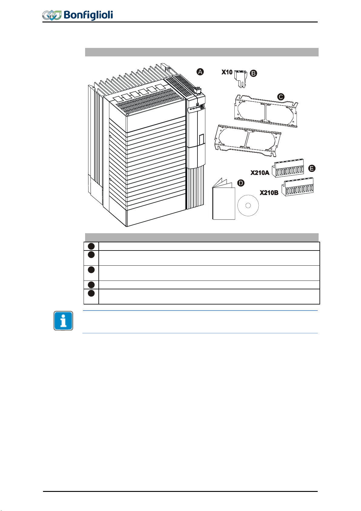
Scope of Supply
A
Frequency inverter
B
Terminal strip X1 (Phoenix ZEC 1,5/ST7,5)
Plug-in terminals for mains connection and DC linking
C
Terminal strip X10 (Phoenix ZEC 1.5/3ST5.0)
Plug-in terminals for the relay output
D
Standard fixtures for vertical assembly
E
Brief Instructions and Operating Instructions on CD ROM
F
Terminal strip X2 (Phoenix ZEC 1,5/ST7,5)
Plug-in terminal for brake resistor and motor connection
G
Control terminals X210A / X210B (Wieland DST85 / RM3.5)
Plug-in terminal for connection of the control signals
Please check incoming goods for quality, quantity and nature without delay. Obvious
defects such as exterior damage of the packing and/or the unit must be notified to the
sender within seven days for insurance reasons.
3 Scope of Supply
grated in the automation concept easily. The scope of delivery described can be supplemented by optional components and adapted to the customer-specific requirements. The plug-
3.1 ACU 201 (up to 3.0 kW) and 401 (up to 4.0 kW)
Scope of Supply
06/13 Operating Instructions ACU 25

Scope of Supply
Scope of Supply
A
Frequency inverter
B
Terminal strip X10 (Phoenix ZEC 1.5/3ST5.0)
Plug-in terminals for the relay output
C
Standard fittings with fitting screws (M4x20, M4x60)
for vertical assembly
D
Brief Instructions and Operating Instructions on CD ROM
E
Control terminals X210A / X210B (Wieland DST85 / RM3.5)
Plug-in terminal for connection of the control signals
Please check incoming goods for quality, quantity and nature without delay. Obvious
defects such as exterior damage of the packing and/or the unit must be notified to the
sender within seven days for insurance reasons.
3.2 ACU 201 (4.0 to 9.2 kW) and 401 (5.5 to 15.0 kW)
26 Operating Instructions ACU
06/13

Scope of Supply
Scope of Supply
A
Frequency inverter
B
Terminal strip X10 (Phoenix ZEC 1.5/3ST5.0)
Plug-in terminals for the relay output
C
Standard fittings with fitting screws (M4x20, M4x70)
for vertical assembly
D
Brief Instructions and Operating Instructions on CD ROM
E
Control terminals X210A / X210B (Wieland DST85 / RM3.5)
Plug-in terminal for connection of the control signals
Please check incoming goods for quality, quantity and nature without delay. Obvious
defects such as exterior damage of the packing and/or the unit must be notified to the
sender within seven days for insurance reasons.
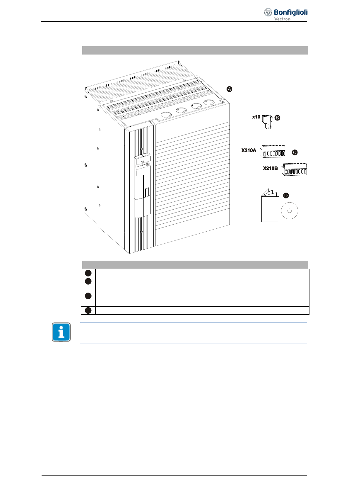
3.3 ACU 401 (18.5 to 30.0 kW)
06/13 Operating Instructions ACU 27
Scope of Supply
Scope of Supply
A
Frequency inverter
B
Terminal strip X10 (Phoenix ZEC 1.5/3ST5.0)
Plug-in terminals for the relay output
C
Standard fittings with fitting screws (M5x20)
for vertical assembly
D
Brief Instructions and Operating Instructions on CD ROM
E
Control terminals X210A / X210B (Wieland DST85 / RM3.5)
Plug-in terminal for connection of the control signals
Please check incoming goods for quality, quantity and nature without delay. Obvious
defects such as exterior damage of the packing and/or the unit must be notified to the
sender within seven days for insurance reasons.
3.4 ACU 401 (37.0 to 65.0 kW)
28 Operating Instructions ACU
06/13
Scope of Supply
A
Frequency inverter
B
Terminal strip X10 (Phoenix ZEC 1.5/3ST5.0)
Plug-in terminals for the relay output
C
Control terminals X210A / X210B (Wieland DST85 / RM3.5)
Plug-in terminal for connection of the control signals
D
Please check incoming goods for quality, quantity and nature without delay. Obvious
defects such as exterior damage of the packing and/or the unit must be notified to the
sender within seven days for insurance reasons.
3.5 ACU 401 (75.0 to 132.0 kW)
Scope of Supply
Brief Instructions and Operating Instructions on CD ROM
06/13 Operating Instructions ACU 29

CE conformity
The frequency inverters ACU meet the requirements of the low voltage directive
2006/95/EEC and EN 61800-5-1.
EMC directive
For proper installation of the frequency inverter in order to meet the requirements of EN
please comply with the installation instructions in these
operating instructions.
Interference
immunity
The frequency inverters ACU meet the requirements of EN 61800-3 for use in
industrial environments.
UL Approval
The frequency inverters marked with the UL label according to UL508c also meet
the requirements of
UL approved are the device series ACU401 in sizes 1 to 7 and ACU201 devices in
sizes 1 and 2.
Safety function
The function is described in the application manual “Safe Torque Off”.
Ambient
temperature
Operation: 0…55 °C; as from 40 °C power reduction has to be considered.
Environmental
class
Operation: 3K3 (EN60721-3-3)
Relative humidity 15…85 %, no water condensation.
Degree
of protection
IP20 if covers and connection terminals are used properly.
Altitude
of installation
Up to 1000 m at rated specifications.
Up to 4000 m at reduced power.
Storage
Storage according to EN 50178.
BONFIGLIOLI VECTRON recommends that the unit be connected to mains voltage for 60 minutes after one year, at the latest.
Overload capability
Continuous Operation: 100 % IN
Up to 150 % I
Up to 200 % IN for 1 s
Devices
(0.25 & 0.37 kW):
Up to 200 % I
Up to 200 % IN for 1 s
The overload capability can be used once in a time cycle of 10 minutes.
Functions
− Control methods adjusted to motors and application (configuration).
−
−
−
−
−
−
−
−
−
−
data set backup, diagnosis with Scope).
Parameterization
− Freely programmable digital inputs and outputs.
−
− Four separate data sets incl. motor parameter.
4 Technical Data
4.1 General technical data
61800-3,
the CSA Standard C22.2-No. 14.
for 60 s
N
Adjustable speed /tor que control.
Various control functions for motor and frequency inverter.
Positioning absolute or relative to a reference point.
Search Run.
Special brake control and load detection for lifting gear.
S-ramps for jerk limitation during acceleration and deceleration.
Technology (PI) controller.
Parameterizable Master-Slave operation via system bus.
Error memory.
Simplified and extended control via PC (commissioning, parameterization,
Various logic modules for linking and processing of signals.
30 Operating Instructions ACU
-01, -03
for 60 s
N
06/13
Loading...