


active
Table of contents
 Loading...
IPNDUSTRY ROCESS
AND UTOMATION OLUTIONSAS
Installation
manual - Cold Plate
Frequency inverter 230 V / 400 V
ACTIVE and
ACTIVE Cube
GB
g
t
g
T
t
g
General points on the documentation
This documentation is valid for the frequency inverter series ACT and ACU in "Cold
Plate" variant (type designation ACT xxx-xxx C, ACU xxx-xxx C).
The "Cold Plate" variant differs from the frequency inverter series ACT and ACU described in the instructions only as regards the design of the heat sink. The installation
instructions complement the documentation by the information relatin
to the varian
details. For all other instructions and information, in particular the safety instructions,
refer to the instructions included in the scope of supply.
The documentation and additional information can be requested via your local repre-
sentation of the company BONFIGLIOLI.
The following pictograms and signal words are used for the purposes of the present
documentation:
Danger
Danger refers to an immediate threat. Non-compliance with the precaution described
may result in death, serious injury or material damage.
Warning
Warning refers to a possible threat. Non-compliance with the warnin
death, serious injury or material damage.
may result in
Caution
Caution refers to an indirect threat. Non-compliance may result in personal or material
damage.
Attention
Attention refers to a possible operational behavior or an undesired condition that can
occur in accordance with the reference text.
Note
Note and the related text provide useful information which supplements the corresponding part of the documentation.
Warning:
he specifications and instructions contained in the documentation mus
be complied with strictly during installation and commissioning. Only qualified staff who has read the documentation and, in particular, the safety
instructions carefully is allowed to carry out installation or commissionin
work or to operate the frequency inverters. The term „Qualified Staff“
refers to anybody who is familiar with the installation, assembly, commissioning and operation of the frequency inverter and has the proper qualification for the job.
11/06 1

TABLE OF CONTENTS
1 Scope of Supply for Devices in "Cold Plate" Variant......................................................3
1.1 ACT/ACU 201 (up to 3.0 kW) and ACT/ACU 401 (up to 4.0 kW)............................. 3
1.2 ACT/ACU 201 (4.0 to 9.2 kW) and ACT/ACU 401 (5.5 to 15.0 kW) ........................ 4
1.3 ACT/ACU 401 (18.5 to 30.0 kW).............................................................................. 5
2 Technical data................................................................................................................ 6
2.1 ACT/ACU 201 (0.55 to 3.0 kW, 230 V) .................................................................... 6
2.2 ACT/ACU 201 (4.0 to 9.2 kW, 230 V)....................................................................... 6
2.3 ACT/ACU 401 (0.55 to 4.0 kW, 400 V) .................................................................... 7
2.4 ACT/ACU 401 (5.5 to 15.0 kW, 400 V) .................................................................... 7
2.5 ACT/ACU 401 (18.5 to 30.0 kW, 400 V) .................................................................. 7
3 Range of application ......................................................................................................8
4 Thermal properties of the heat sink............................................................................... 9
4.1 Thermal resistance .................................................................................................. 9
4.1.1 ACT/ACU 201 (0.55 to 3.0 kW, 230 V).....................................................................10
4.1.2 ACT/ACU 201 (4.0 to 9.2 kW, 230 V)....................................................................... 10
4.1.3 ACT/ACU 401 (0.55 to 4.0 kW, 400 V).....................................................................11
4.1.4 ACT/ACU 401 (5.5 to 15.0 kW, 400 V).....................................................................11
4.1.5 ACT/ACU 401 (18.5 to 30.0 kW, 400 V)...................................................................12
4.2 Fan and liquid cooling............................................................................................ 13
5 Application notes ......................................................................................................... 14
6 Mechanical installation ................................................................................................ 15
6.1 ACT/ACU 201 (up to 3.0 kW) and ACT/ACU 401 (up to 4.0 KW) .......................... 15
6.2 ACT/ACU 201 (4.0 to 9.2 kW) and ACT/ACU 401 (5.5 to 15.0 kW) ...................... 16
6.3 ACT/ACU 401 (18.5 to 30.0 kW)............................................................................ 17
6.4 Installation ............................................................................................................18
7 Temperature Monitoring.............................................................................................. 18
2 11/06
T
g
g
g
t
1 Scope of Supply for Devices in "Cold Plate" Variant
he scope of supply of the "Cold Plate" variant differs from the scope defined in the
operatin
instructions as regards the heat sink design and the standard fixtures which
are not required in this variant.
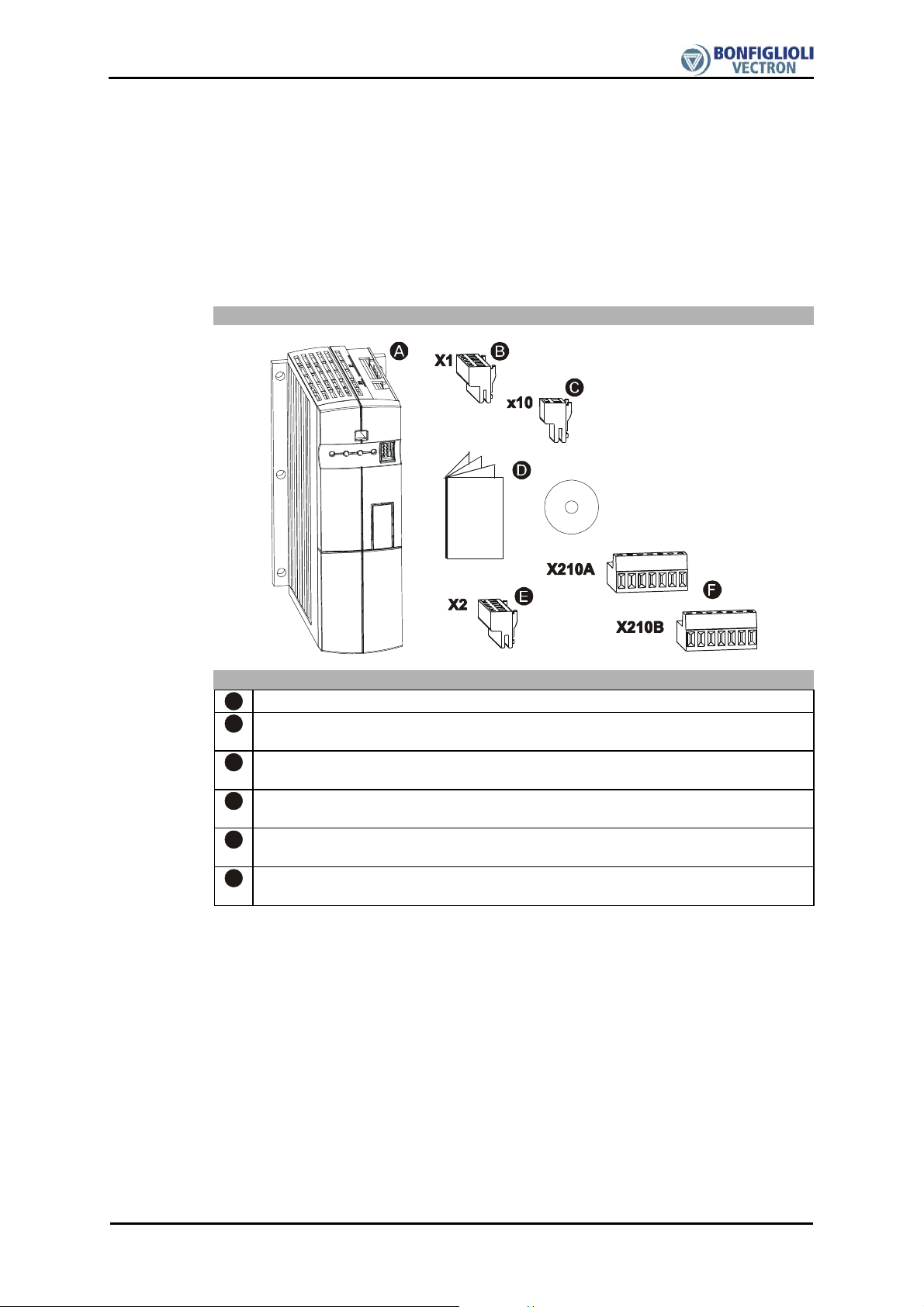
1.1 ACT/ACU 201 (up to 3.0 kW) and ACT/ACU 401 (up to
4.0 kW)
Scope of Supply
Scope of supply
A
Frequency inverter
Terminal bar X1 (Phoenix ZEC 1,5/ST7,5)
B
Plug-in terminals for mains connection and DC networking
Terminal bar X10 (Phoenix ZEC 1,5/3ST5,0)
C
Plug-in terminals for relay output
Instructions and installation instructions for the device in "Cold Plate" variant,
D
CD ROM with manuals
Terminal bar X2 (Phoenix ZEC 1,5/ST7,5)
E
Plug-in terminal for braking resistor and motor connection
Control terminals X210A / X210B (Wieland DST85/RM3,5)
F
Plug-in terminal for connection of control signals
Note: Immediately check the
oods received for quality, quantity and type.
Obvious defects such as exterior dama
must be notified to the sender within seven days for insurance reasons.
e of the packing and/or the uni
11/06 3

g
g
t
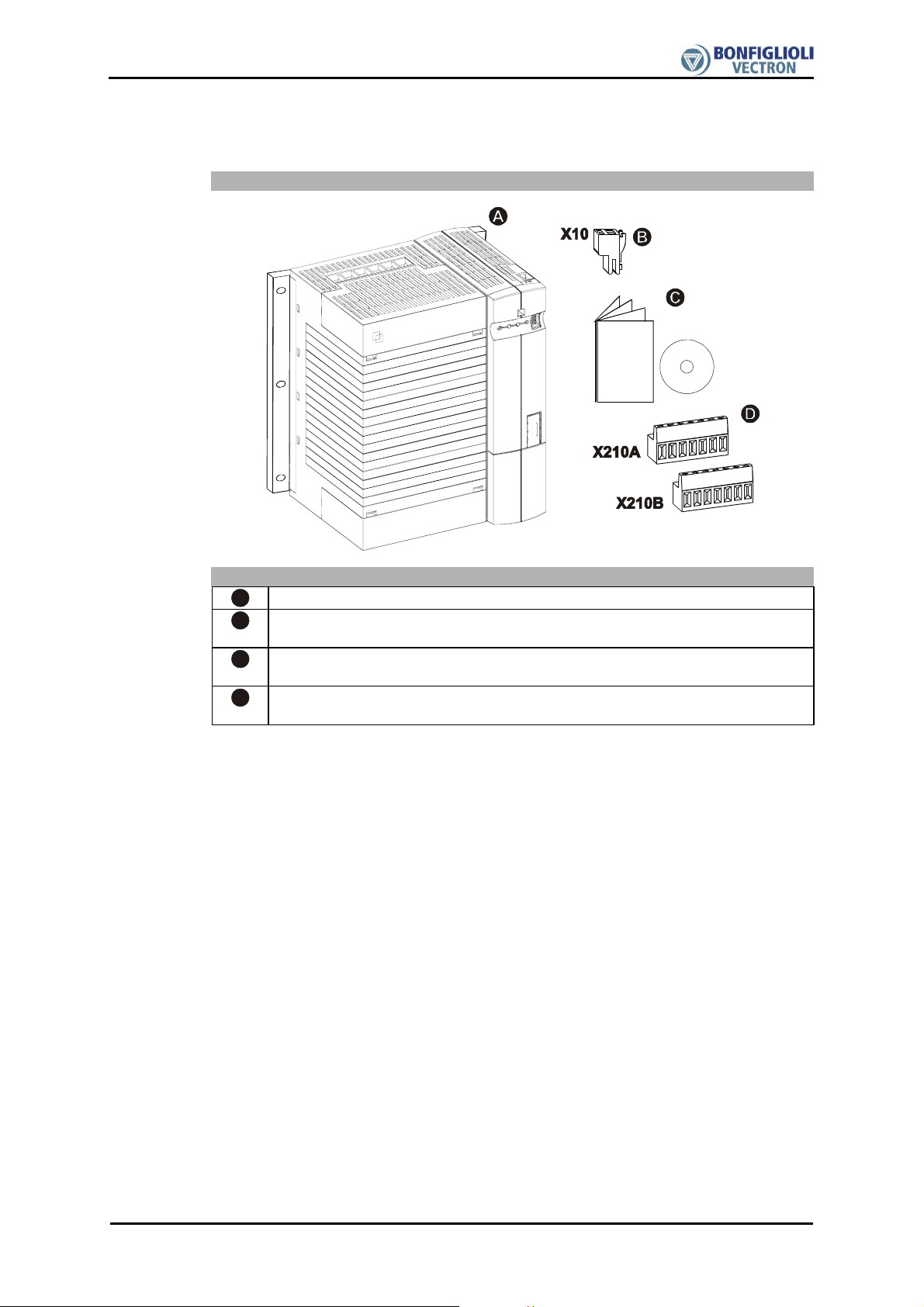
1.2 ACT/ACU 201 (4.0 to 9.2 kW) and ACT/ACU 401 (5.5 to
15.0 kW)
Scope of Supply
Scope of supply
A
Frequency inverter
Terminal bar X10 (Phoenix ZEC 1,5/3ST5,0)
B
Plug-in terminals for relay output
Instructions and installation instructions for the device in "Cold Plate" variant,
C
CD ROM with manuals
Control terminal X210A / X210B (Wieland DST85/RM3,5)
D
Plug-in terminal for connection of control signals
Note: Immediately check the
oods received for quality, quantity and type.
Obvious defects such as exterior dama
must be notified to the sender within seven days for insurance reasons.
e of the packing and/or the uni
4 11/06
g
t
1.3 ACT/ACU 401 (18.5 to 30.0 kW)
Scope of Supply
Scope of supply
A
Frequency inverter
Terminal bar X10 (Phoenix ZEC 1,5/3ST5,0)
B
Plug-in terminals for relay output
Instructions and installation instructions for the device in "Cold Plate" variant,
C
CD ROM with manuals
Control terminal X210A / X210B (Wieland DST85/RM3,5)
D
Plug-in terminal for connection of control signals
Note: Immediately check the goods received for quality, quantity and type.
Obvious defects such as exterior dama
e of the packing and/or the uni
must be notified to the sender within seven days for insurance reasons.
11/06 5
t
2 Technical data
The following tables contain the technical data of the frequency inverter series ACT and
ACU in the "Cold Plate" variant. The recommended motor shaft output applies to the
corresponding nominal voltage of the frequency inverter according to the instructions a
a switching frequency of 2 kHz. The weights and dimensions differ from the data listed
in the instructions. The dimensions are valid for the frequency inverter without plug-in
terminals and with cold plate in the "Cold Plate" device variant. For the other technical
data refer to the enclosed instructions.
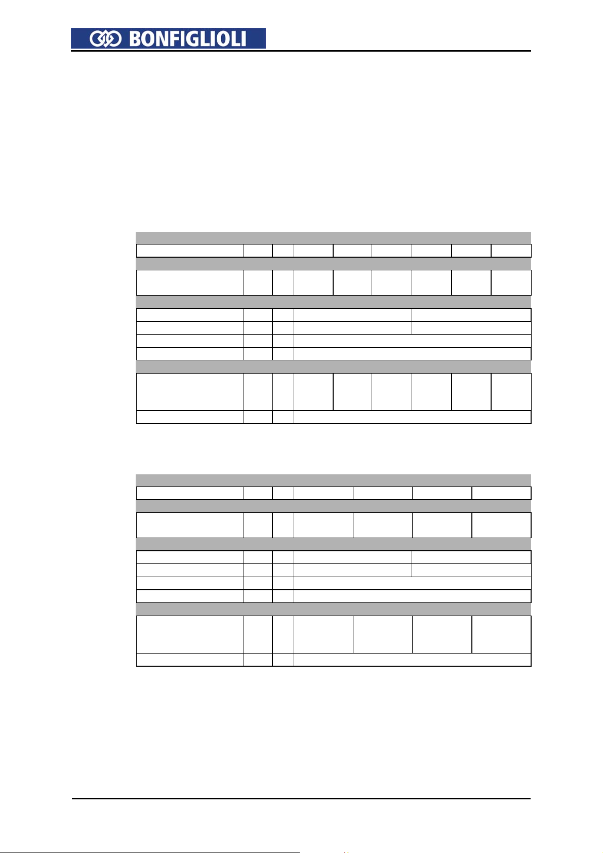
2.1 ACT/ACU 201 (0.55 to 3.0 kW, 230 V)
Type designation
ACT/ACU 201 -05 -07 -09 -11 -13 -15
Motor-side output
Recommended
motor shaft output
P kW 0.55 0.75 1.1 1.5 2.2 3.0
Mechanical
Dimensions
HxWxD
mm 190x82x140 250x85x140
Weight (approx.) m kg 1.2 1.6
Type of protection - - IP20 (EN60529)
Installation position - - vertical
Environmental conditions
Energy dissipation
(at 2 kHz switching
P W 43 53 73 84 115 170
frequency)
Coolant temperature Tn °C 0 ... 40 (3K3 DIN IEC 721-3-3)
2.2 ACT/ACU 201 (4.0 to 9.2 kW, 230 V)
Type designation
ACT/ACU 201 -18 -19 -21 -22
Motor-side output
Recommended
motor shaft output
Mechanical
Dimensions
Weight (approx.) m kg 2.2 3.1
Type of protection - - IP20 (EN60529)
Installation position - - vertical
Environmental conditions
Energy dissipation
(at 2 kHz switching
frequency)
Coolant temperature Tn °C 0 ... 40 (3K3 DIN IEC 721-3-3)
P kW 4.0 5.5 7.5 9.2
HxWxD
mm 250x125x144 250x150x144
P W 200 225 310 420
6 11/06
Loading...