

Page 1
Owner's Manual
A - Z
Contents
Online Edition for Part-No. 01 41 0 158 448 - © 09/04 BMW AG
for Vehicle
The Ultimate
Driving Machine
Page 2

X3 2.5i
Online Edition for Part-No. 01 41 0 158 448 - © 09/04 BMW AG
X3 3.0i
Owner's Manual for Vehicle
We are very glad that you have decided to purchase a BMW.
The more familiar you are with it, the more secure you will be on
the roads. This is why we ask you:
Please read the information we have gathered for you in this
Owner's Manual before you set off with your new BMW. You will
receive important information on vehicle operation that enables
you to make full use of the technical benefits of your BMW. You
will also find information on maintenance that serves to retain the
operating and road safety as well as the best possible value
retention of your vehicle. You will find supplementary information
in other brochures.
This Owner's Manual should be considered a permanent part of
this vehicle. It should stay with the vehicle when sold to provide
the next owner with important operating, safety and maintenance
information.
We wish you an enjoyable driving experience.
BMW AG
Page 3

© 2004 Bayerische Motoren Werke
Online Edition for Part-No. 01 41 0 158 448 - © 09/04 BMW AG
Aktiengesellschaft
Munich, Germany
Reprinting, including excerpts,
only with the written consent of
BMW AG, Munich.
Order No. 01 41 0 158 448
US English VIII/04
Printed in Germany
Printed on environmentally friendly paper,
bleached without chlorine, suitable for recycling.
Page 4

Contents
Online Edition for Part-No. 01 41 0 158 448 - © 09/04 BMW AG
The fastest way to find specific topics is to use
the index, refer to page 113.
Using this Owner's Manual
4 Notes
At a glance
10 Cockpit
Controls
16 Opening and closing
24 Adjustments
31 Transporting children safely
34 Driving
42 Everything under control
46 Technology for comfort, convenience
and safety
53 Lamps
56 A congenial climate
62 Practical interior accessories
Driving tips
72 Things to remember when driving
Mobility
80 Refueling
82 Wheels and tires
88 Under the hood
93 Maintenance
95 Replacing components
103 Giving and receiving assistance
Reference
110 Technical data
113 Everything from A to Z
Reference At a glanceControlsDriving tipsMobility
Page 5
Notes
Online Edition for Part-No. 01 41 0 158 448 - © 09/04 BMW AG
Using this Owner's Manual
Notes
We have made every effort to ensure that you
are able to find what you need in this Owner's
Manual as quickly as possible. The fastest way
to find certain topics is by using the detailed
index at the end. For a brief initial overview,
please refer to the first chapter.
Should you sell your BMW some day, please
remember to hand over the Owner's Manual as
well; it is an important component of your vehicle.
Additional sources of information
If you have additional questions, your BMW
Sports Activity Vehicle Center is always happy
to advise you.
You can find information on BMW, e.g. technology, on the Internet at www.bmwusa.com.
Symbols used
Indicates precautions that must be fol-
lowed precisely in order to avoid the possibility of personal injury and serious damage to
the vehicle.
Indicates information that will assist you
in gaining the optimum benefit from your
vehicle and enable you to care more effectively
for your vehicle.
Refers to measures that can be taken to
help protect the environment.
< Marks the end of a specific item of informa-
tion.
*
Indicates special equipment, country-specific
equipment and optional extras, as well as
equipment and functions not yet available at the
time of printing.
Vehicle Memory, Key Memory, refer to
page 30. Identifies functions that can be
specifically adapted for a particular key or vehicle. These adjustments can be performed by
your BMW Sports Activity Vehicle Center.
Symbols on vehicle components
Indicates that you should consult the rel-
evant section of this Owner's Manual for
information on a particular part or assembly.
4
Page 6

The individual vehicle
Online Edition for Part-No. 01 41 0 158 448 - © 09/04 BMW AG
On purchasing your BMW, you have decided in
favor of a model with individualized equipment
and features. This Owner's Manual describes
all models and equipment that BMW offers
within the same group.
We hope you will understand that equipment
and features are included that you might not
have chosen for your vehicle. Sections describing options and special equipment are marked
*
by asterisks
ble differences between the descriptions in this
manual and your own vehicle's equipment.
If equipment in your BMW is not described in
this Owner's Manual, please refer to the accompanying Supplementary Owner's Manuals.
to assist you in identifying possi-
Editorial notice
BMW pursues a policy of continuous, ongoing
development that is conceived to ensure that
our vehicles continue to embody the highest
quality and safety standards combined with
advanced, state-of-the-art technology. In isolated cases it is possible that the features
described in this Owner's Manual could differ
from those on your vehicle.
5
Reference At a glanceControlsDriving tipsMobility
Page 7

For your own safety
Online Edition for Part-No. 01 41 0 158 448 - © 09/04 BMW AG
Maintenance and repair
Notes
Advanced technology, e.g. the use of
modern materials and high-performance
electronics, requires specially adapted maintenance and repair methods. Therefore, only have
corresponding work on your BMW carried out
by a BMW Sports Activity Vehicle Center or a
workshop that works according to BMW repair
procedures with correspondingly trained personnel. If work is carried out improperly, there is
a danger of consequential damage and the
related safety risks.<
California Proposition 65 Warning
California law requires us to state the following
warning:
Engine exhaust and a wide variety of
automobile components and parts,
including components found in the interior furnishings in a vehicle, contain or emit chemicals
known to the State of California to cause cancer
and birth defects and reproductive harm. In
addition, certain fluids contained in vehicles and
certain products of component wear contain or
emit chemicals known to the State of California
to cause cancer and birth defects or other
reproductive harm.
Battery posts, terminals and related accessories contain lead and lead compounds. Batteries also contain other chemicals known to the
State of California to cause cancer. Wash your
hands after handling. Used engine oil contains
chemicals that have caused cancer in laboratory animals. Always protect your skin by washing thoroughly with soap and water.<
Parts and accessories
For your own safety, use genuine parts
and accessories approved by BMW.
When you purchase accessories tested and
approved by BMW and Genuine BMW Parts,
you simultaneously acquire the assurance that
they have been thoroughly tested by BMW to
ensure optimum performance when installed
on your vehicle.
BMW warrants these parts to be free from
defects in material and workmanship.
BMW will not accept any liability for damages
resulting from installation of parts and accessories not approved by BMW.
BMW cannot test every product made by other
manufacturers to verify if it can be used on a
BMW safely and without risk to either the vehicle, its operation or its occupants.
Genuine BMW Parts, BMW Accessories and
other products approved by BMW, together
with professional advice on using these items,
are available from all BMW Sports Activity Vehicle Centers.
Installation and operation of non-BMW
approved accessories such as alarms, radios,
amplifiers, radar detectors, wheels, suspension
components, brake dust shields, telephones,
including operation of any mobile phone from
within the vehicle without using an externally
mounted antenna, or transceiver equipment, for
instance CBs, walkie-talkies, ham radios or similar accessories may cause extensive damage
to the vehicle, compromise its safety, interfere
with the vehicle's electrical system or affect the
validity of the BMW Limited Warranty. Refer to
your BMW Sports Activity Vehicle Center for
additional information.<
Maintenance, replacement, or repair of
the emission control devices and systems may be performed by any automotive
repair establishment or individual using any certified automotive part.<
6
Page 8

Service and warranty
Online Edition for Part-No. 01 41 0 158 448 - © 09/04 BMW AG
We recommend that you read this publication
thoroughly.
Your BMW is covered by the following warranties:
> New Vehicle Limited Warranty
> Rust Perforation Limited Warranty
> Federal Emissions System Defect Warranty
> Federal Emissions Performance Warranty
> California Emission Control System Limited
Warranty.
Detailed information about these warranties is
listed in the Service and Warranty Information
Booklet for US models or in the Warranty and
Service Guide Booklet for Canadian models.
Reporting safety defects
The following only applies to vehicles owned
and operated in the US.
If you believe that your vehicle has a defect
which could cause a crash or could cause injury
or death, you should immediately inform the
National Highway Traffic Safety Administration
NHTSA in addition to notifying BMW of North
America, LLC, P.O. Box 1227, Westwood,
New Jersey 07675-1227, telephone toll-free
1-800-831-1117.
If NHTSA receives similar complaints, it may
open an investigation, and if it finds that a safety
defect exists in a group of vehicles, it may order
a recall and remedy campaign. However,
NHTSA cannot become involved in individual
problems between you, your dealer, or BMW of
North America, LLC.
To contact NHTSA, you may either call the Auto
Safety Hotline toll-free at 1-800-424-9393 or
366-0123 in Washington, D.C. area, or write to:
NHTSA, U.S. Department of Transportation,
Washington, D.C. 20590. You can also obtain
other information about motor vehicle safety
from the Hotline.
7
Reference At a glanceControlsDriving tipsMobility
Page 9
Online Edition for Part-No. 01 41 0 158 448 - © 09/04 BMW AG
Page 10
At a glance
Online Edition for Part-No. 01 41 0 158 448 - © 09/04 BMW AG
At a glance
This overview of buttons, switches and displays
is intended to familiarize you with your
vehicle's operating environment.
The section will also assist you in becoming
acquainted with the control concepts
and options available for operating
the various systems.
Page 11

Cockpit
Online Edition for Part-No. 01 41 0 158 448 - © 09/04 BMW AG
Controls
Cockpit
1 Parking lamps/low beams 53
2 > Turn signals 38
> Roadside parking lamps 54
> High beams 54
> Headlamp flasher 38
> Computer
3 Fog lamps
4 Horn
5 Washer/wiper system/rain sensor
6 Hazard warning flashers
*
44
*
54
10
7 Central locking system 16
8 Unlocking the hood 88
*
38
Page 12
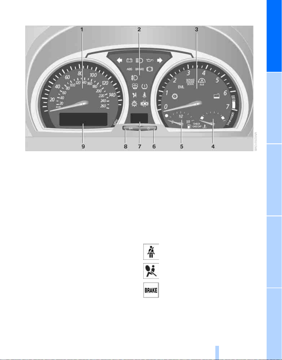
Instrument cluster
Online Edition for Part-No. 01 41 0 158 448 - © 09/04 BMW AG
At a glanceControlsDriving tipsMobilityReference
1 Speedometer
2 Indicator and warning lamps 11
3 Tachometer 42
Indicator and warning lamps 11
4 Coolant temperature gage 42
5 Fuel gage 42
6 Button for
> Displaying the time 43
> Service Interval Display 43
7 Selector lever and program display for
automatic transmission 36
8 Button for
> Resetting trip odometer 42
> Setting the time 43
9 Display for
> Trip odometer/odometer 42
> Time 43
> Service Interval 43
> Computer 44
Indicator and warning lamps
Technology that monitors itself
The indicator and warning lamps identified by
the Χ are subjected to an operation check each
time you switch on the engine. They each light
up once for different periods of time.
When a malfunction occurs in a monitored system, the corresponding lamp will either fail to go
ou t w he n th e e ng ine is sta rt ed, o r i t wil l c ome o n
again during normal driving. Detailed information is provided on the specified pages.
Please fasten safety belt +27
Airbags
Brake system
With handbrake released 49, 92
With handbrake engaged 35
With other warning lamps 49
+
51
+
11
Page 13
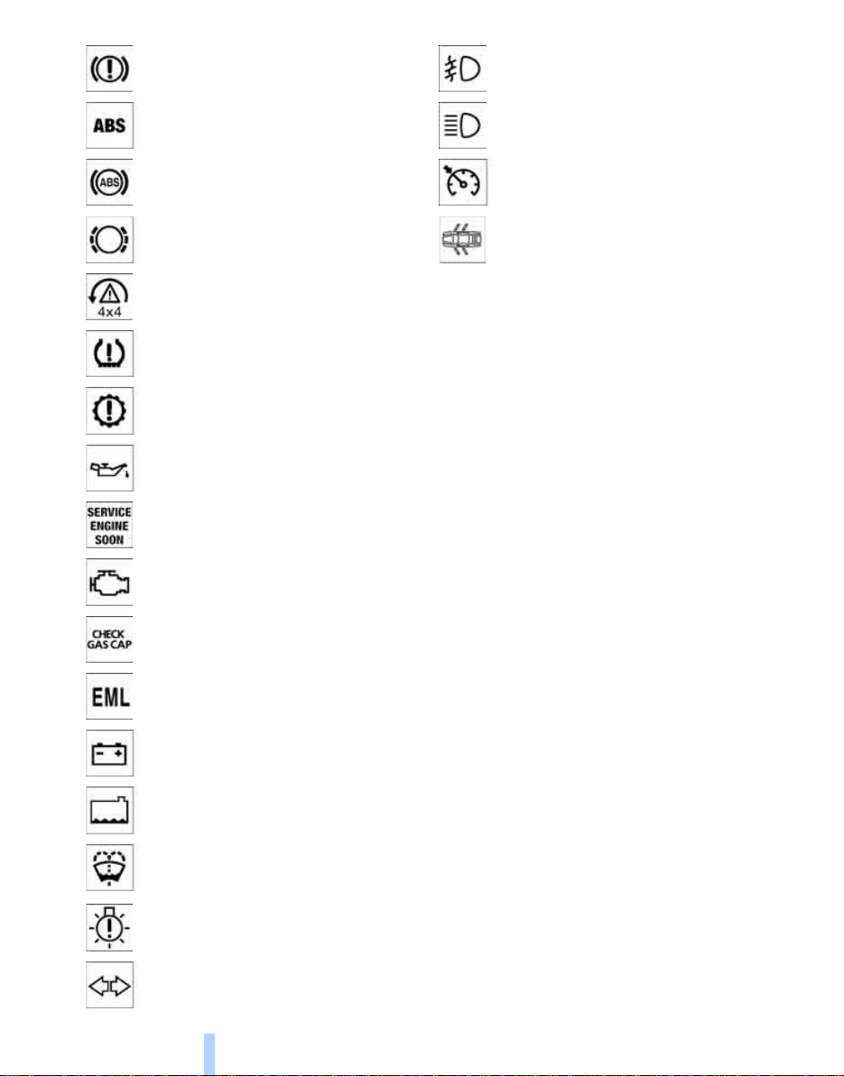
Brake warning lamp for Canadian
Online Edition for Part-No. 01 41 0 158 448 - © 09/04 BMW AG
models
Front fog lamps 54
Driving stability control systems/
ABS Antilock Brake System
Cockpit
ABS Antilock Brake System/chassis
control system for Canadian models
Brake pads
DSC Dynamic Stability Control/
xDrive
Flat Tire Monitor
Automatic transmission
Engine oil
Service Engine Soon
Service Engine Soon warning lamp for
Canadian models
Check Gas Cap
Engine electronics
Battery charge current
+
+
47, 49
+
90
92
+
*
+80
Headlamp flasher 38
+
49
High beams 54
Cruise control 40
Indicates from ignition key in position 2 when a door or the tailgate is
opened.
Colors
49
+
36
+
94
+
34
+
101
The indicator and warning lamps can light up in
different colors and combinations.
The following section explains the significance
of the individual colors as well as how you
should respond when they appear.
> red:
Stop the vehicle immediately
or
an important reminder
> yellow:
Have the system inspected as soon as
possible
or
For your information
> green:
For your information
> blue:
For your information
Topping off coolant 91
Topping off washer fluid 90
Lamp defective 53
Turn signals 38
12
Buttons on steering wheel*
The buttons integrated into the steering wheel
are provided so that you can operate a number
of accessories quickly and without being distracted from traffic conditions. You may operate:
> Selected audio source functions
> Recirculated-air mode/steering wheel
heater
Page 14
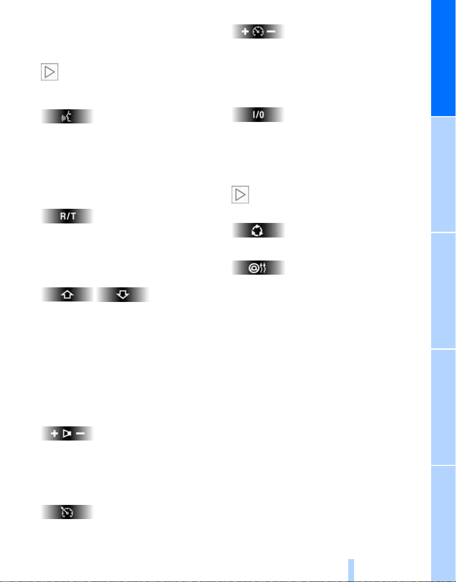
> Cruise control
Online Edition for Part-No. 01 41 0 158 448 - © 09/04 BMW AG
> Selected telephone functions
> Voice command system
In order to operate a system, the corresponding system m ust be switched on.<
Telephone*/voice command system*
Cruise control: storing and accelerating
well as braking and storing
On the sports steering-wheel* the buttons +/–
for the cruise control are located on the righthand side of the steering wheel.
–
+
as
At a glanceControlsDriving tipsMobilityReference
Press briefly:
Accept incoming call, start dialing, terminate
call.
Extended pressure:
Activate/deactivate voice command system
Telephone*/audio sources*
Display/hide phonebook. Display the entries
consecutively with the buttons for fast forward/
reverse
Fast forward/reverse
> Radio
Press briefly: next station
> CD
Press briefly: skip track
Extended pressure: fast forward/reverse
> Phone
Browse through list of names
Cruise control: activating/interrupting/deactivating
Recirculated-air mode/steering wheel
heater*
Depending on the equipment, there is a
button for the recirculated-air mode or
steering wheel heater.<
Switching recirculated-air mode on and off
Steering wheel heater: switching on/off, refer to
page 28.
Volume
On the sports steering-wheel* the buttons +/–
for volume are located on the left-hand side of
the steering wheel.
Cruise control*
Cruise control: resume
13
Page 15
Online Edition for Part-No. 01 41 0 158 448 - © 09/04 BMW AG
Page 16
Controls
Online Edition for Part-No. 01 41 0 158 448 - © 09/04 BMW AG
Controls
This chapter is intended to provide you with
information for complete control of your vehicle.
Its extensive array of features and accessories,
both for driving and for your own safety,
comfort and convenience, are described here.
Page 17
Opening and closing
Online Edition for Part-No. 01 41 0 158 448 - © 09/04 BMW AG
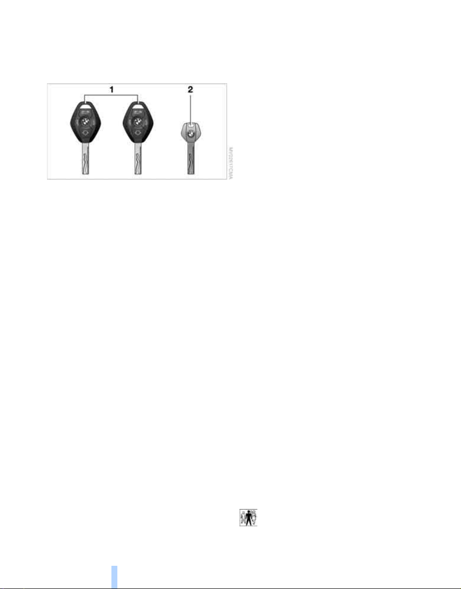
Key set
1 Master keys with remote control
Opening and closing
Every master key with remote control contains an extended-life battery as a power
supply, which is charged automatically in
the ignition lock as you drive. You should
use each master key at least twice a year in
order to maintain the charge condition.
Depending on which master key is detected
by the vehicle during unlocking, different
settings in the vehicle are requested and
executed, refer to Vehicle and Key Memory
on page 30.
2 Spare key
For storage in a safe place, such as in your
wallet.
This key does not fit in the lock of the glove
compartment. This is an advantage, e.g.
when valet parking at a hotel. The key is not
intended for constant use.
Central locking system
The concept
The central locking system is ready for operation whenever the driver's door is closed. The
system engages or releases the locks on the
> doors
> tailgate
> fuel filler door
The central locking system can be operated
from the outside
> via the remote control
> via the driver's door lock
and from inside via the button for the central
locking system.
When the system is locked from inside, the fuel
filler door remains unlocked, refer to page 18.
The anti-theft system is automatically activated
whenever you activate the central locking system from outside the vehicle. This prevents the
doors from being unlocked via the lock buttons
or door handles. The alarm system is also
armed or disarmed.
In the event of a serious accident, the central
locking system unlocks automatically. In addition, the hazard warning flashers and interior
lamps switch on.
Replacement keys
Replacement and additional keys are available
from your BMW Sport Activity Vehicle Center.
16
Opening and closing: from outside
Using the remote control
When you engage/release the vehicle locks,
you also activate/deactivate the anti-theft system, arm/disarm
the interior lamps on/off.
You can set an acoustic signal to remind
you if the ignition key is still in the ignition
lock after you open the driver's door.<
the alarm system, and switch
Page 18
Protect the remote control against unau-
Online Edition for Part-No. 01 41 0 158 448 - © 09/04 BMW AG
thorized use by handing over only the
spare key, for example when using hotel valet
parking.<
For additional details on the alarm system, refer
to page 22.
Because any persons or animals left unat-
tended in a parked vehicle could lock the
doors from the inside, you should always keep
the remote control with you; this precaution
ensures that you will remain able to unlock the
vehicle from the outside at all times.<
Switching on interior lamps
Press the button if the vehicle is locked.
You can also use this function to locate your
vehicle in parking garages etc.
Panic mode*
By pressing and holding the button for more
than approx. two seconds, you can trigger the
*
alarm system
danger.
To switch off the alarm: press any of the buttons.
in response to any impending
Unlocking
Press the button.
Press the button once to unlock the driver's
door only; press a second time to unlock all
remaining doors as well as the tailgate and the
fuel filler door.
Convenience opening mode
Press and hold the button. The windows and
the panorama glass sunroof open.
If you desire, you can have this special
feature activated/deactivated on a vehicle-specific basis.<
Locking and securing
Press the button.
If you desire, the vehicle locks automati-
cally if no door or lid is opened after
unlocking. You may have this function set on a
vehicle-specific basis if you wish.<
As confirmation for the fact that the vehicle is
properly locked, the hazard warning flashers
light up.
If you wish, you can have this special fea-
ture deactivated on vehicles without an
alarm system.<
Switching off tilt alarm sensor* and
*
interior motion sensor
Press the button again directly after
locking.
For details, refer to page 23.
Unlocking tailgate
Press the button.
The tailgate will open slightly, regardless of
whether it was previously locked or unlocked.
Before and after a trip, ensure that the
tailgate has not been opened unintentionally.
A previously locked tailgate is also locked again
after closing.<
If you desire, the tailgate can only be
opened using the remote control if the
vehicle is unlocked. This can be adjusted.<
Malfunctions
The remote control may malfunction due to
local radio waves.
Should the remote control fail to operate owing
to interference of this kind, unlock and lock the
vehicle via the door lock using the master key.
If it is no longer possible to lock the vehicle via
the remote control, the battery is discharged.
Use this remote control during an extended
drive; this will recharge the battery, refer to
page 16.
For US owners only
The transmitter and receiver units comply with
part 15 of the FCC/Federal Communications
Commission regulations. Operation is governed by the following:
FCC ID: LX8EWS
LX8FZVS
17
Reference At a glanceControlsDriving tipsMobility
Page 19
LX8FZVE
Online Edition for Part-No. 01 41 0 158 448 - © 09/04 BMW AG
Compliance statement:
This device complies with part 15 of the FCC
Rules. Operation is subject to the following two
conditions:
> This device may not cause harmful interfer-
ence.
and
> This device must accept any interference
received, including interference that may
cause undesired operation.
Any unauthorized modifications or
changes to these devices could void the
user's authority to operate the equipment.<
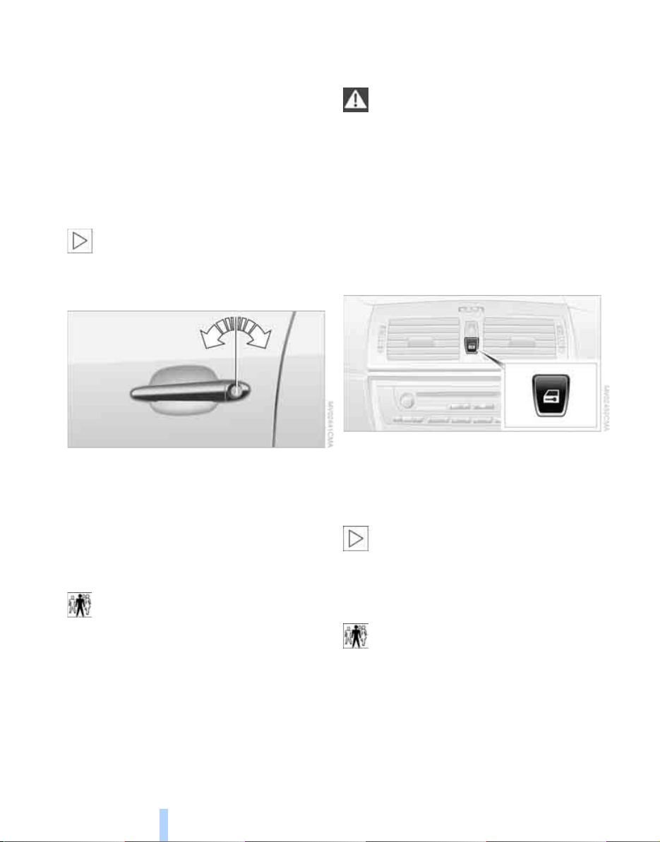
Opening and closing
Using door lock
> To close:
With the door closed, turn the key to the
Lock position and hold it.
Watch during the closing process to be
sure that no one is injured. Releasing the
key stops the operation.<
Manual operation
If an electrical malfunction occurs, you can
unlock or lock the driver's door with the key in
the end positions of the door lock.
Opening and closing: from inside
One turn of the key in the driver's door lock
unlocks the driver's door only.
Turning the key a second time unlocks all of the
remaining doors, the tailgate and the fuel filler
door.
As confirmation for the fact that the vehicle is
properly locked, the hazard warning flashers
light up.
If you wish, you can have this special feature deactivated on vehicles without an
alarm system.<
Convenience operation
You also have the option of operating the windows and the panorama glass sunroof from the
driver's door lock.
> To open:
With the door closed, turn the key to the
Unlock position and hold it there.
18
You can use this button to operate the central
locking system when the front doors are closed.
With this button, only the doors and the tailgate
are unlocked or locked. The anti-theft system is
not activated.
If only the driver's door was unlocked
from the outside and you press the button, then, with the driver's door still open, the
passenger-side door, the tailgate and the fuel
filler door will also unlock.
If the driver's door is closed, it will be locked.<
The central locking system locks auto-
matically after driving off. This can be
adjusted to be vehicle-specific or key-specific.<
Page 20
Unlocking and opening doors
Online Edition for Part-No. 01 41 0 158 448 - © 09/04 BMW AG
1. Press button for central locking system.
2. Pull the respective door handle above the
armrest.
or
individually pull on the door handle of each door
twice to unlock and open.
Engaging locks
> Press button for central locking system.
or
> Press down the lock buttons of the doors.
To prevent you from being locked out, the
opened driver's door cannot be locked
using the lock button.
Because any persons or animals left unat-
tended in a parked vehicle could lock the
doors from the inside, you should always keep
the key with you; this precaution ensures that
you will remain able to unlock the vehicle from
the outside at all times.<
Tailgate
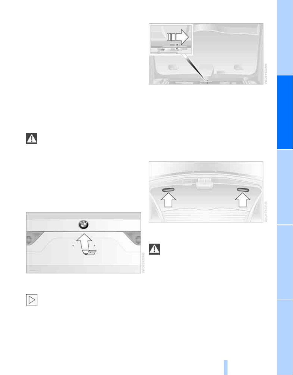
Manual unlocking
In the event of an electrical malfunction:
1. Fold up the floor cover in the cargo area.
2. Release the jack from the bracket.
3. Press the lever behind the cover to the side,
refer to arrow.
The tailgate is locked again as soon as you
close it.
Closing
Opening from outside
Press the button in the handle strip. The tailgate
is unlocked and opens somewhat.
During opening, the tailgate pivots back
and up. Ensure that adequate clearance is
available before opening.<
When the tailgate is open, the cargo area and
interior are lit up.
The handle recesses on the interior trim of the
tailgate make it easier to pull down.
To avoid injuries, be sure that the travel
path of the tailgate is clear when it is
closed, as with all closing procedures.<
19
Reference At a glanceControlsDriving tipsMobility
Page 21
Windows
Online Edition for Part-No. 01 41 0 158 448 - © 09/04 BMW AG
Opening and closing windows
would continue closing.
You can disable the anti-trapping mechanism
by pressing the switch beyond the resistance
point and holding it.<
Following interruptions in electrical
power supply
After disconnecting the battery, the anti-trapping mechanism must be reinitialized. To do
this, open and close the windows once and continue pull the switch for longer than 2 seconds
after closing.
As of ignition key position 1:
> Press the switch up to the resistance point:
Opening and closing
The window continues to move as long as
you continue to press the switch.
> Briefly press the switch beyond the resis-
tance point:
The window moves downward automatically. Briefly press the switch again to stop
the opening motion.
You can close the windows in the same manner
by pulling the switch.
After switching off ignition
You can operate the power windows for up to
15 minutes as long as neither of the front doors
has been opened.
When leaving the vehicle, always remove
the key and close the doors, as otherwise
children could operate the windows and injure
themselves.<
For convenience operation using the door lock,
refer to page 18.
Anti-trapping mechanism
If the closing force rises beyond a predefined
threshold during closing, the system will immediately stop moving the window prior to lowering it slightly.
Despite the anti-trapping mechanism you
should always inspect the window's travel
path prior to closing it, as the safety system
might fail to detect certain kinds of obstructions, such as very thin objects, and the window
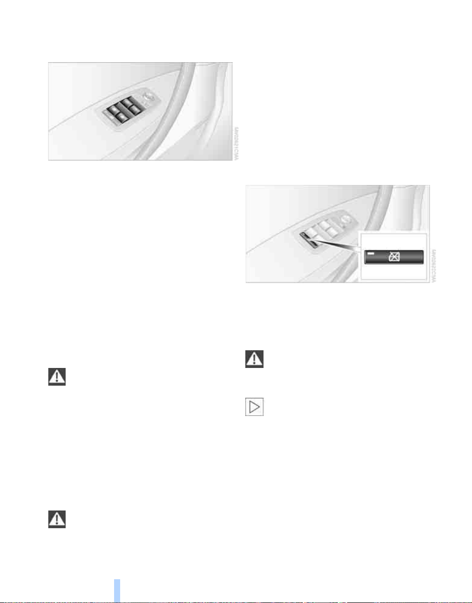
Safety switch
With the safety switch, you can prevent the rear
windows from being opened or closed via the
switches in the rear passenger area, by children, for example. The indicator lamp lights up
when this safety feature is activated.
Always press the safety switch when children ride in the rear, as otherwise
unchecked closing of the windows could lead to
injuries.<
You can deactivate the function again as
of ignition key position 1.<
Accessories in window area
After installing any accessory – such as a
clamp-on antenna for a portable phone – within
the window's travel range, you will need to have
the system reinitialized for use under the new
conditions. Please contact your BMW Sports
Activity Vehicle Center.
20
Page 22
Panorama glass sunroof*
Online Edition for Part-No. 01 41 0 158 448 - © 09/04 BMW AG
When leaving the vehicle, always remove
the key and close the doors, as otherwise
children could operate the sunroof and injure
themselves.<
The panorama glass sunroof is operational from
ignition key position 1.
After the ignition has been switched off:
You can operate the panorama glass sunroof for
up to 1 minute as long as neither of the doors
has been opened.
Raising, opening, closing
Press the switch or slide it in the desired direction up to the resistance point.
Release the switch to stop the motion.
The sliding visor is opened slightly when the
panorama glass sunroof is raised.
The panorama glass sunroof can be opened or
closed independently with the sliding visor
open.
Ventilation setting
The panorama glass sunroof is raised and the
sliding visor is opened slightly: Briefly press the
switch twice consecutively.
Automatic opening and closing
Briefly press the switch past the resistance
point and then release it.
Briefly pressing the switch again stops the
motion.
Opening and closing panorama glass
sunroof and sliding visor together
Briefly press the switch beyond the resistance
point twice consecutively.
Briefly pressing the switch again stops the
motion.
Comfort position
Each time the panorama glass sunroof is completely opened or closed, it stops in the comfort
position. If desired, continue the motion following this with the switch.
In the comfort position the wind noise in the
interior is reduced.
Anti-trapping mechanism
If the panorama glass sunroof or sliding visor
encounter resistance when closing from
roughly one third of the sunroof opening or
when closing from the raised position, the closing action is interrupted and the panorama
glass sunroof and sliding visor reopen a little.
Despite the anti-trapping mechanism
inspect the sunroof's travel path prior to
closing it, as the safety system might fail to
detect certain kinds of obstructions, such as
very thin objects, and the sunroof would continue closing.
The anti-trapping mechanism for closing the
panorama glass sunroof is deactivated if the
switch is pressed beyond the resistance point
and held there. The closing action is interrupted
when you release the switch.<
Following interruptions in electrical
power supply
Following interruptions in electrical power, for
instance, when the battery is disconnected, it is
possible that the panorama glass sunroof will
extend to its tilt-up position, but fail to respond
to other commands. The system must be initialized. BMW recommends having this work carried out by your BMW Sports Activity Vehicle
Center.
21
Reference At a glanceControlsDriving tipsMobility
Page 23
Manual operation
Online Edition for Part-No. 01 41 0 158 448 - © 09/04 BMW AG
In the event of an electrical malfunction, you can
operate the panorama glass sunroof manually.
1. Pull off the cover firmly downward.
2. Insert the Allen wrench from the compart-
Opening and closing
ment beneath the cargo area floor, refer to
page 99, into the proper opening and turn
the panorama glass sunroof in the desired
direction. Direction of rotation for closing,
refer to arrow.
The system responds to unauthorized vehicle
entry and attempted theft by simultaneously
activating:
> The acoustic alarm for approx. 30 seconds.
> The hazard warning flashers for approx.
5minutes.
> The high beams, which flash on and off in
the same rhythm.
Arming and disarming alarm system
When you lock or unlock the vehicle, either with
the remote control or at the door lock, the alarm
system is armed or disarmed at the same time.
If the alarm system has been properly armed,
the hazard warning flashers light up once.
You can have different acknowledgment
signals set to confirm arming and disarm-
ing.<
You can also open the tailgate with the system
armed using the button on the remote control, refer to page 17. When you close the tailgate, the system is rearmed.
Switching off alarm
> Unlock the vehicle using the remote control,
refer to page 17.
or
> Turn the ignition key to position 1.
Alarm system*
The concept
The vehicle alarm system responds:
> When a door, the hood, or the tailgate is
opened.
> To movements inside the vehicle: interior
motion sensor, refer to Tilt alarm sensor
and interior motion sensor.
> To changes in the vehicle tilt angle such as
occur during attempts to steal the wheels or
tow the vehicle.
> To interruptions in battery voltage.
22
Indicator lamp displays
> The indicator lamp below the interior rear-
view mirror flashes continuously: the system is armed.
Page 24
> The indicator lamp flashes when the vehicle
Online Edition for Part-No. 01 41 0 158 448 - © 09/04 BMW AG
is locked: door(s) or tailgate are not completely closed. Even if you do not close the
alerted area, the system begins to monitor
the remaining areas, and the indicator lamp
flashes continuously after 10 seconds.
However, the interior motion sensor is not
activated.
> The indicator lamp goes out when the vehi-
cle is unlocked: no manipulation or
attempted intrusions have been detected in
the period since the system was armed.
> The indicator lamp flashes for 10 seconds
after the vehicle is unlocked: an attempted
entry has been detected in the period since
the system was armed.
Following triggering of an alarm, the indicator
lamp will flash continuously.
Tilt alarm sensor and interior motion
sensor
Tilt alarm sensor
The tilt of the vehicle is monitored. The alarm
system reacts, e.g. in case of an attempted
wheel theft or towing.
Switching off tilt alarm sensor and
interior motion sensor
Press the button on the remote control
again directly after locking.
The indicator lamp lights up briefly and then
flashes continuously. The tilt alarm sensor and
the interior motion sensor are switched off until
the next time the vehicle is unlocked and subsequently locked again.
If you wish, the tilt alarm sensor and inte-
rior motion sensor are permanently
switched off. You can have this set at your
BMW Sports Activity Vehicle Center.<
If you interrupt the convenience closing of
the windows and panorama glass sunroof
within the first 10 seconds and then reinitiate
the action, this will unintentionally switch off the
tilt alarm sensor and interior motion sensor.
If this has occurred, the system must be disarmed and then rearmed.<
Interior motion sensor
In order for the interior motion sensor to function properly, the windows and panorama glass
sunroof must be completely closed.
Avoiding unintentional alarms
The tilt alarm sensor and interior motion sensor
may be switched off at the same time. This prevents unintentional alarms, e.g. in the following
situations:
> In stacking garages
> When transporting on car-carrying trains
> When animals are to remain in the vehicle
23
Reference At a glanceControlsDriving tipsMobility
Page 25

Adjustments
Online Edition for Part-No. 01 41 0 158 448 - © 09/04 BMW AG
Sitting safely
The ideal sitting position can make a vital contribution to relaxed driving that is as fatigue-free
as possible. The sitting position plays an important role together with the safety belts, head
restraints and airbags in providing occupants
Adjustments
with maximum levels of passive safety in an
accident. Therefore, observe the following
instructions, as otherwise the protective function of the safety systems may be impaired.
For additional information on transporting children safely, refer to page 31.
Airbags
Always maintain an adequate distance
between yourself and the airbags. Always
hold the steering wheel by its rim with hands at
the 9 o'clock and 3 o'clock positions, to minimize the risk of injuries to your hands and arms
in the event of airbag deployment.
No one and nothing is to come between the airbags and the seat occupant.
Do not use the cover of the front airbag on the
front passenger side as a storage area. Make
sure that the front passenger is correctly seated
and does not place feet or legs against the
instrument panel, as otherwise leg injuries can
result if the front airbag is triggered. Never let an
occupant's head rest near or on a side airbag
because the inflating airbag could cause a serious or fatal injury.<
Even if you adhere to all the instructions, injuries resulting from contact with airbags cannot
be fully excluded, depending on the circumstances. The ignition and inflation noise may
provoke a mild – usually temporary – hearing
loss in extremely sensitive individuals.
For airbag locations and additional information
on airbags, refer to page 31.
Safety belts
Make sure the safety belts are worn in all occupied seats every time you drive. Although airbags enhance safety by providing added protection, they are not a substitute for safety
belts.
Your vehicle has five seats that are all equipped
with a safety belt.
Occupants should sit upright and be
properly restrained at all times: infants
and small children in appropriate child-restraint
systems; larger children and adults using the
safety belts.
Never allow more than one person to wear a single safety belt. Infants and children must not
ride on a lap.
Expectant mothers should always wear their
safety belts, taking care to position the lap belt
against the lower hips, where it will not exert
pressure against the abdominal area. The
safety belt must not rest against the neck, nor
be wedged in any way or permitted to rub
against sharp edges. Avoid twisting the belt
while routing it snugly across the hips and
shoulder, as close to the body as possible, without resting against hard or fragile objects. Otherwise, in the event of a frontal impact, a loose
lap belt could slide over your hips, leading to
abdominal injury. Avoid wearing clothing that
prevents the belt from fitting properly and pull
the shoulder belt upward periodically to readjust the tension across your lap in order to avoid
a reduction in the restraining action of the
safety belt.<
If the middle safety belt in the rear is used, then
the wider backrest must be secured, refer to
page 67, otherwise, the safety belt cannot exert
any restraining action.
For fastening safety belts, refer to page 27.
24
Page 26
Seats
Online Edition for Part-No. 01 41 0 158 448 - © 09/04 BMW AG
Note before adjusting
Never try to adjust your seat while operat-
ing the vehicle. The seat could respond
with unexpected movement, and the ensuing
loss of vehicle control could lead to an accident.
On the passenger side as well, do not recline
the backrest too far while the vehicle is being
driven, as otherwise there is a danger of sliding
under the safety belt during an accident, eliminating the protection normally provided by the
belt.<
Please observe the information on using safety
belts provided on page 27 and the information
on the head restraints on page 25.
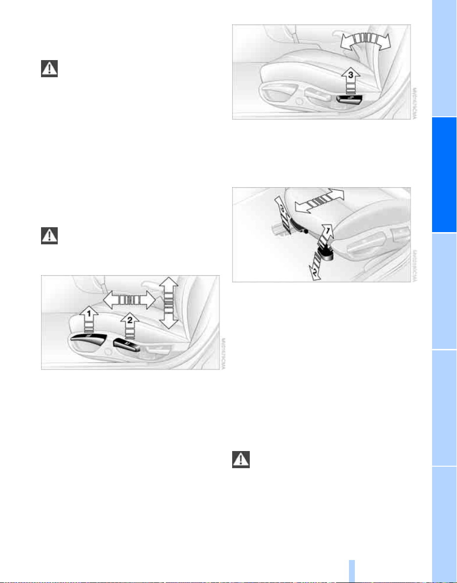
Seat adjustment
To ensure that the safety systems con-
tinue to provide optimized protection,
please observe the adjustment instructions
above.<
1 Longitudinal direction
Pull the lever and slide the seat into the
desired position.
After you release the lever, move the seat
forward or backward slightly so that it
engages fully.
2 Height
Pull the lever and apply weight to or remove
weight from the seat as required.
3 Backrest
Pull the lever and apply weight to or remove
weight from the backrest as required.
Adjusting sports seat*
You can also adjust the tilt and the thigh
support:
1 Upward tilt
Pull the lever as many times as required to
set the desired tilt.
2 Downward tilt
Press the lever as many times as required to
set the desired tilt.
3 Thigh support
Pull the lever and move the thigh support in
a longitudinal direction.
Head restraints
Head restraints reduce the risk of injury to
cervical vertebrae when accidents occur.
Adjust the head restraints so that their middles
are approximately at ear height.<
25
Reference At a glanceControlsDriving tipsMobility
Page 27
Adjustments
Online Edition for Part-No. 01 41 0 158 448 - © 09/04 BMW AG
Adjustments
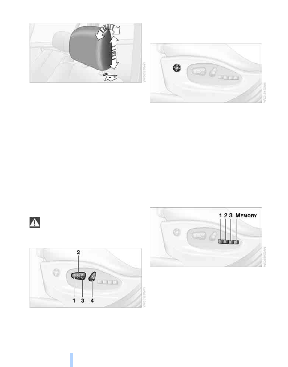
Height adjustment:
> To raise: pull upward.
> To lower: press button, arrow 1, and slide
head restraint downward.
Front head restraint tilt angle: adjust by tilting.
Removing front head restraint
1. Pull the head restraint upward to the stop.
2. Press button, arrow 1, and pull head
restraint all the way out.
Installing front head restraint
1. Press button, arrow 1, and slide the head
restraint into its sockets.
2. Adjust the head restraint.
Setting the head restraint manually, refer to
above paragraph.
Lumbar support*
You can also adjust the contours of the backrest
to obtain additional support in the lumbar
region.
The upper hips and spinal column receive supplementary support to help you maintain a
relaxed, upright sitting position.
> To increase or decrease curvature: press
switch forward or back.
> To move curvature up or down: press
switch up or down.
Seat and mirror memory*
Power seat*
To ensure that the safety systems continue to provide optimal protection,
please observe the adjustment instructions on
page 24.<
1 Tilt
2 Longitudinal direction
3 Height
4 Backrest
26
You can store and select three different adjustment settings for the driver's seat and exterior
mirrors.
The adjustment of the lumbar support is not
stored in the memory.
Storing
1. Turn the ignition key to position 1 or 2.
2. Set the desired seat and exterior mirror
position.
Page 28
3. Press the MEMORY button:
Online Edition for Part-No. 01 41 0 158 448 - © 09/04 BMW AG
The indicator lamp in the button lights up.
4. Press the desired memory button 1, 2 or 3:
The indicator lamp goes out.
Requesting a stored setting
Do not request a position from the memory while the vehicle is moving, as other-
wise there is a risk of accident from unexpected
seat movement.<
Convenience mode
1. Open the driver's door after unlocking or
turn the ignition key to position 1.
2. Briefly press the desired memory button 1,
2 or 3.
The system immediately cancels the
adjustment procedure when you press one
of the seat adjustment buttons or use one o f
the memory buttons.
Safety feature
1. Close the driver's door and turn the ignition
key to position 0 or 2.
2. Press the desired memory button 1, 2 or 3
and maintain pressure until the adjustment
process has been completed.
If you press the
dentally:
Press the button a second time – the indicator
lamp goes out.<
You can have your vehicle programmed
to automatically recall your own individual
adjustment settings for the seat and exterior
mirror position whenever you use your personal
remote control to unlock the vehicle.<
If you make use of this adjustment, be
sure that the footwell behind the driver's
seat is unobstructed before unlocking the vehicle. If you fail to do so, any persons, animals or
objects behind the seat could be injured or
damaged by a rearward movement of the
seat.<
M
EMORY button acci-
Heated seats*
The seat cushion and backrest can be heated
when the ignition key is in position 2.
To request different temperature levels: press
the button repeatedly.
To switch off from a higher heat setting: press
the button and hold it slightly longer.
Safety belts
To ensure that the safety systems continue to provide optimal protection,
please follow the instructions on page 24.<
Make sure the safety belts are worn in all occupied seats every time you drive. Although airbags enhance safety by providing added protection, they are not a substitute for safety
belts.
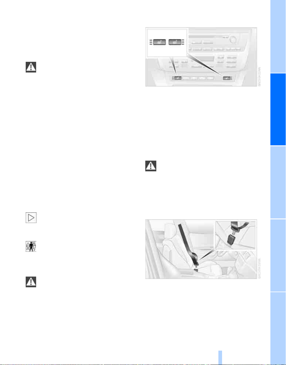
Fastening
Make sure you hear the latch plate engage in
the belt buckle.
Releasing
1. Press the red button in the belt buckle.
2. Hold the belt firmly.
27
Reference At a glanceControlsDriving tipsMobility
Page 29
3. Guide the belt back into its reel.
Online Edition for Part-No. 01 41 0 158 448 - © 09/04 BMW AG
The upper shoulder strap's anchorage point will
be in the correct position for seat occupants of
every build if the seat is correctly adjusted, refer
to page 24.
The two rear safety belt buckles integrated into
the rear seat are for passengers sitting on the
left and right. The belt buckle embossed with
the word CENTER is intended exclusively for
use by passengers riding in the center posi-
Adjustments
tion.<
Safety belt reminder for front seats
The indicator lamp flashes or lights up.
In addition, a signal sounds. Please
make sure that the safety belts are
being worn correctly.
The safety belt reminder is activated if the
safety belt on the driver's side has not yet been
fastened.
At speeds greater than 5 mph/8 km/h, the
safety belt reminder is also activated if the passenger side safety belt has not yet been fastened, if heavy objects are placed on the passenger's seat, or if the front passenger's safety
belt is released.
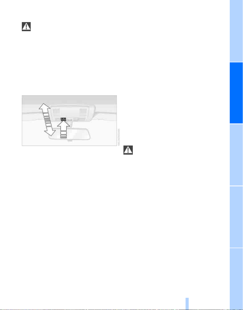
Steering wheel
Adjustments
Do not adjust the steering wheel while the
vehicle is moving. There is a risk of acci-
dent from unexpected movement.<
1. Fold the clamping lever downward.
2. Adapt the steering wheel in the longitudinal
direction and height of the seat position.
3. Fold the clamping lever back up.
Steering wheel heater*
The button for steering wheel heater is located
on the steering wheel, refer to page 12.
Damage to safety belts
If the safety belts are damaged or
stretched in an accident: have the entire
belt system, including the tensioning mechanisms, replaced at your BMW Sports Activity
Vehicle Center or at a workshop that works
according to BMW repair procedures with correspondingly trained personnel. Have the belt
anchorage points inspected for damage at the
same time. Failure to observe this precaution
may prevent the safety belts from effectively
providing optimal protection when needed. If a
child-restraint system was in the vehicle during
an accident, consult the manufacturer's
instructions regarding replacement.<
28
Steering wheel heater: switching on/off
The steering wheel heater operates as of ignition key position 2.
Press the button to activate or deactivate this
system.
The indicator lamp within the button lights up
when the steering wheel heater is in operation.
Mirrors
Exterior mirrors
The mirror on the passenger side fea-
tures a lens with a more convex surface
than the mirror installed on the driver's side.
When estimating the distance between yourself
and other traffic, bear in mind that the objects
reflected in the mirror are closer than they
appear. This means that estimations of the
Page 30
distance to following traffic should not be
Online Edition for Part-No. 01 41 0 158 448 - © 09/04 BMW AG
regarded as precise.<
Tilting down passenger's mirror,
automatic parking function*
1 Adjustments
2 Switching over to the other mirror or to the
automatic parking function
Storing the mirror positions, refer to Seat and
mirror memory on page 26.
To prevent the exterior mirrors on this
vehicle from being damaged, always fold
them in by hand before entering an automatic
car wash.<
*
Manual adjustments
You can also adjust the mirrors manually if need
be: by pressing the edges of the mirror glass.
Automatic heating
When the outside temperature falls below a
specified temperature, both outside mirrors are
automatically heated whenever the engine is
running or the ignition is switched on.
Activating
1. Select the driver's exterior mirror with
switch 1.
2. When you shift into reverse or move the
selector-lever into position R, the exterior
mirror glass on the front passenger side tilts
downward slightly. This allows the driver to
see the area immediately adjacent to the
vehicle – such as a curb – when parking, etc.
You can have the angle of downward tilt
set to depend on the key used.<
Deactivating
Select the front passenger's exterior mirror with
switch 1.
Interior rearview mirror
To reduce the dazzle effect of following vehicles at night, turn the knob.
29
Reference At a glanceControlsDriving tipsMobility
Page 31

Vehicle Memory, Key Memory
Online Edition for Part-No. 01 41 0 158 448 - © 09/04 BMW AG
How the system functions
You have probably frequently wished that you
could configure individual functions of your
vehicle to reflect your own personal requirements. In developing your vehicle, BMW has
incorporated a number of options for personal
adjustment. You can have these programmed
at your BMW Sports Activity Vehicle Center.
Adjustments
There are vehicle-related and person-related
adjustments: Vehicle Memory and Key Memory. You can configure up to four different basic
adjustments for four different persons. The only
requirement is that each person uses his or her
own master key with remote control.
When your vehicle is unlocked with the remote
control, the vehicle recognizes the individual
user by means of a data exchange with the key,
and makes adjustments accordingly.
In order for you to distinguish between the master keys with remote control, color-coded
decals are supplied together with the keys.
What the system can do
Your BMW Sports Activity Vehicle Center can
provide you with details on the capabilities of
the Vehicle Memory and Key Memory systems.
You will see this symbol throughout the
Owner's Manual. It is to remind you at
appropriate places of the settings that are available to you.<
Following configuration of memory func-
tions, vehicle operation may differ from
the description in the Owner's Manual. Should
you want to sell your BMW some day, please
remember to have the memory functions reset
to the factory default settings.<
Examples of Vehicle Memory functions
> Different acknowledgment signals to con-
firm locking/unlocking of the vehicle, refer
to page 16.
> Activating/deactivating function for path-
way lighting, refer to page 53.
> Activating/deactivating daytime driving
lamps, refer to page 53.
> Setting measurement units for displays in
the instrument cluster for time, outside
temperature, distance driven and fuel consumption, refer to page 44.
> Active PDC Park Distance Control is indi-
cated by an acoustic sound signal when
reverse gear or selector lever position R is
engaged, refer to page 46.
> The rear window defroster switches on
automatically, refer to page 57.
> Different acknowledgment signals to con-
firm arming/disarming the alarm system,
refer to page 22.
> After an ice warning has been issued, the
computer display returns to the previous
adjustment, refer to page 44.
> Acoustic warning if the ignition key remains
in the ignition lock after the driver's door has
been opened, refer to page 19.
Examples of Key Memory functions
> When unlocking, first unlock the driver's
door, then the entire vehicle, refer to
page 17.
> Locking the vehicle after moving off, refer to
page 18.
> Automatic adjustment of the driver's seat
and exterior mirror position for each person
when unlocking the vehicle, refer to
page 27.
> Angle of downward tilt of mirror on passen-
ger side, refer to page 29.
30
Page 32

Transporting children safely
Online Edition for Part-No. 01 41 0 158 448 - © 09/04 BMW AG
The right place for children
Children always in the rear
Accident research shows that the safest place
for children in a vehicle is in the rear seat.
Older children should be tightly secured with a
safety belt, after they have outgrown a booster
seat that is appropriate for their age, height and
weight.
If your vehicle is equipped with rear side
airbags, do not allow children to lean
toward the door trim, as serious injuries could
occur if the side airbags are deployed and children are too close to the airbags.<
Deactivating side airbags in the rear
Labels in the rear door opening should indicate
the status of your rear seat side airbags. If you
are uncertain of their status, or wish to have the
airbags activated or deactivated, please co ntact
your BMW Sports Activity Vehicle Center.
Child-restraint system in rear
Children under 13 years of age and chil-
dren less than 5 ft/150 cm tall should
always ride in the rear and the restraint systems
should be properly secured.<
Younger children should be secured in an
appropriate child restraint system that has been
first properly secured to the vehicle.
All rear seating positions in your vehicle meet
the recommendations of SAE J1819, an industry-recommended practice for securing childrestraint systems in motor vehicles.
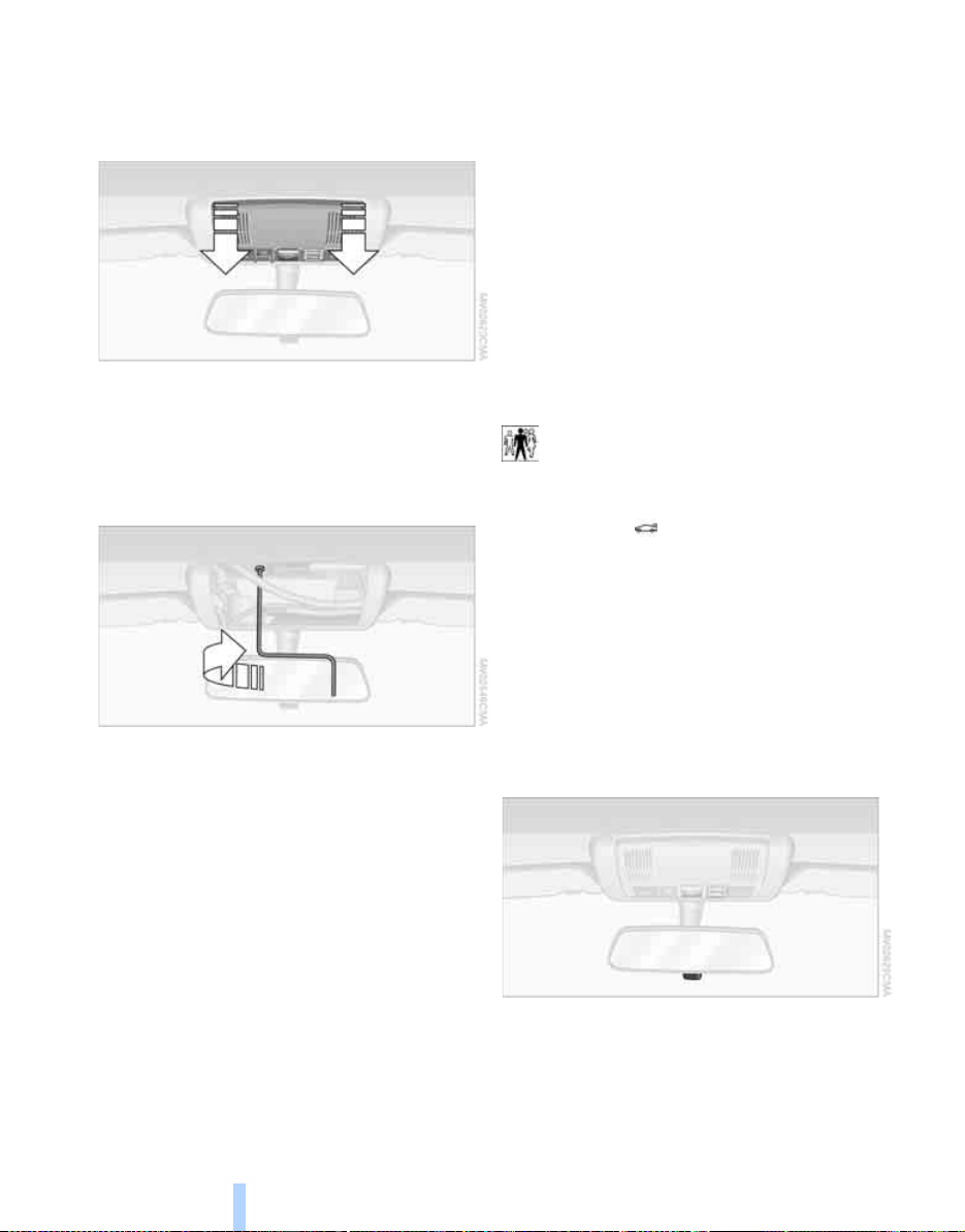
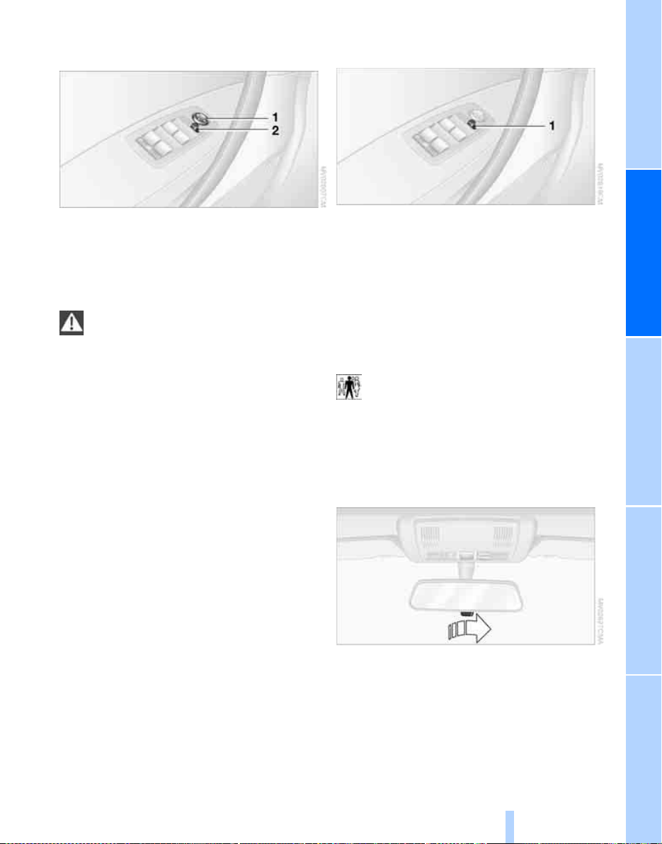
Exception for the front passenger seat
Should it become necessary to use a
child-restraint system on the front passenger seat, the airbags on the passenger side
must be deactivated. The passenger airbag
indicator lamp above the interior rearview mirror
must light up continuously. Otherwise, the front
passenger airbags remain active and there is
considerable risk of injury to children if the airbags are triggered, even with a child-restraint
system. In this case, children should be seated
in the rear and the system should be checked at
your BMW Sport Activity Vehicle Center.<
Never install a rearward-facing child-
restraint system in the front passenger
seat of this vehicle if the passenger airbag is not
deactivated. If you do so, the child could be
severely injured when the airbag is triggered.
Your vehicle is equipped with an airbag supplemental restraint system for the front passenger.
Because the backrest on any rearward-facing
child-restraint system – of the kind designed for
infants under 1 year and 20 Ibs./9 kg – would be
within the airbag's deployment range, you
should never mount such a system in the front
passenger seat, since the impact of the airbag
against the child restraint's backrest could lead
to serious or fatal injuries.<
More information on automatic deactivation of
the front passenger airbags, refer to page 52.
Installing child-restraint systems
Before installing any child-restraint system or
child seat, read the following:
Observe the child-restraint system man-
ufacturer's instructions for selection,
installation and use of the child-restraint system. Otherwise the degree of protection can be
reduced.
After an accident, have all parts of the relevant
vehicle safety belt system checked by a BMW
Sports Activity Vehicle Center and replaced if
necessary.<
Commercially-available child-restraint systems
are designed to be secured with a lap belt or
with the lap belt portion of a combination lap/
shoulder belt. Improperly or inadequately
installed restraint systems can increase the risk
31
Reference At a glanceControlsDriving tipsMobility
Page 33

of injury to children. Always read and follow the
Online Edition for Part-No. 01 41 0 158 448 - © 09/04 BMW AG
instructions that come with the system.
Child seat security
All of the rear belt retractors and the front passenger's safety belt can be locked for mounting
and securing child-restraint systems.
Information regarding this is located near the
buckle latch of each safety belt.
To lock the safety belt
Pull the entire length of the belt from the belt
Transporting children safely
retractor. Allow the reel to retract the belt
somewhat and engage the buckle, then tighten
the belt against the child-restraint system. The
retraction mechanism is now locked.
lift the plastic plug with the help of a screwdriver. Depending on the location selected for
seating in the rear passenger area, attach the
tether strap to the corresponding anchorage
point to secure the child-restraint system, as
shown in the illustration below.
Routing of tether strap
Outer seating positions:
Route the tether strap through the center
between the head restraint and the backrest.
Center seating position:
Fold the center armrest forward and pull the
tether strap through the opening. Then fold up
the center armrest and engage it.
To unlock the safety belt
Release the buckle, remove the child-restraint
system and allow the belt retractor to reel the
belt completely in.
Child-restraint system with tether
strap
If you use a child-restraint system with a tether
strap, three additional tether anchorage points
have been provided, refer to the arrows in the
illustration. To gain access to this anchor fitting
32
When using the cargo area cover: tether strap
must run between the rear backrest and the
cargo area cover.
Page 34

Adjust the tether strap according to the
Online Edition for Part-No. 01 41 0 158 448 - © 09/04 BMW AG
child-restraint manufacturer's instruc-
tions.<
LATCH child-restraint fixing system*
LATCH: Lower Anchor and Tethers for CHildren.
The rear outer seating positions are provided
with anchors for a LATCH child-restraint fixing
system.
To fit the LATCH child-restraint fixing
system, follow the operating and safety
instructions of the system manufacturer.<
Child-safety lock of rear doors
Slide down the safety levers on the rear doors:
The door can now be opened from the outside
only.
Access to anchorage points
The picture shows the right rear seat as an
example. The anchorage points for the LATCH
child-restraint fixing system are located behind
the cover caps.
Remove the cover caps toward the front.
Press on to remount.
Before attachment of the LATCH child-restraint
fixing system, remove the cover caps and pull
the belt out of the region of the child-restraint
fixing system.
For driving
With side airbags in the rear, make sure
that children do not lean out of the child's
seat toward the door panel, as otherwise major
injuries can result if the side airbags are triggered.<
You can have the rear side airbags permanently
deactivated.
Your BMW Sports Activity Vehicle Center will
be happy to advise you.
Safety switch for power windows
Always press the safety switch for the power
windows, refer to page 20, when children are in
the rear of the vehicle.
33
Reference At a glanceControlsDriving tipsMobility
Page 35

Driving
Online Edition for Part-No. 01 41 0 158 448 - © 09/04 BMW AG
Ignition lock
Driving
0 Steering locked
Th e ke y can b e in serte d or rem oved i n th is pos ition only.
After removing the key, turn the steering wheel
slightly to the left or right until you hear the lock
engage.
Interlock
Vehicles with automatic transmission:
To turn the key back to position 0 or to remove
it, first place the selector lever in position P.
1 Steering unlocked
A slight steering wheel movement often makes
it easier to turn the key from 0 to 1.
Some power accessories are ready for operation.
2 Ignition switched on
All vehicle systems are ready for operation.
3 Starting engine
Engine
Do not allow the engine to warm up while idling.
Begin driving immediately at moderate engine
speed.
The engine idle speed is controlled by the
engine computer system. Increased idle
speeds at startup are normal and should
decrease as the engine warms up. If engine
speed does not decrease, service is required.
To prevent the battery from discharging, alwa ys
switch off electrical devices which are not in use
and the ignition when the vehicle is not being
driven.
Do not run the engine in closed rooms, as
otherwise inhaling toxic exhaust gases
can cause unconsciousness and death. The
exhaust gases contain carbon monoxide, an
odorless and colorless, but highly toxic gas.
Do not leave the vehicle unattended with the
engine running, since an unattended vehicle
with a running engine represents a safety hazard.
When driving, standing at idle and while parking
take care to avoid possible contact between a
hot exhaust system and any highly flammable
materials such as hay, leaves, grass etc. Such
contact could lead to a fire, resulting in serious
personal injury and property damage.<
Indicator lamps
If the Service Engine Soon indicator
lamp comes on either continuously or
intermittently, this indicates a malfunction in the emissions-related electronic systems. Although the vehicle remains operational,
you should have the systems checked by your
BMW Sports Activity Vehicle Center at the earliest possible opportunity.
The illuminated indicator informs you of the
need for service, not that you need to stop the
vehicle. However, the systems should be
checked by your BMW Sports Activity Vehicle
Center at the next opportunity.
If the indicator blinks or flashes, this indicates
a high level of engine misfire. Reduce speed
and contact the nearest BMW Sports Activity
Vehicle Center immediately. Severe engine
misfiring over even a short period of time can
seriously damage emission control system
components, especially the catalytic converter.
34
Page 36

Display of the previously described
Online Edition for Part-No. 01 41 0 158 448 - © 09/04 BMW AG
malfunction on Canadian models.
The warning lamp lights up. Malfunction in the engine electronics. You can
continue to drive with reduced engine
output or speed. Have the system checked
immediately.
Starting engine
When starting the engine, do not press the
accelerator pedal.
Vehicles with manual transmission:
Step on the clutch when starting the vehicle.
A locking mechanism prevents the engine from
starting if the clutch is not depressed.
Do not end the starting procedure too early, but
do not prolong it for more than 20 seconds.
Release the ignition key immediately as soon as
the engine starts.
If the engine fails to start on the first attempt, for
instance, if it is very hot or cold:
Press the accelerator pedal halfway down while
engaging the starter.
During a cold start at very low temperatures,
below approx. +57/–15 6, at high altitudes
over 3,300 ft/1,000 m:
> Engage the starter for approx. 10 seconds
the first time.
> Press the accelerator pedal halfway down
while engaging the starter.
Avoid frequent starting in quick succes-
sion or repeated start attempts in which
the engine does not start. Otherwise, the fuel is
not burned or inadequately burned and there is
a danger of overheating and damaging the catalytic converter.<
Manual transmission
1. Apply the handbrake.
2. Shift into neutral.
3. Press the clutch pedal.
If the clutch pedal is not pressed, the engine
cannot be started.
4. Start the engine.
Before leaving the vehicle with the engine
running, place the gearshift lever in neutral position and engage the handbrake.
Never leave an unattended vehicle with the
engine running, as such a vehicle represents a
potential safety hazard.<
Automatic transmission
1. Press the brake pedal.
2. Engage selector-lever position P or N.
3. Start the engine.
To prevent the vehicle from rolling,
always select position P and engage the
handbrake before leaving the vehicle with the
engine running. Never leave an unattended
vehicle with the engine running, as such a vehicle represents a potential safety hazard.<
Switching off engine
Do not remove the ignition key when the
vehicle is moving, as otherwise the steering could lock.
When leaving the vehicle, always remove the
ignition key and lock the steering.
When parking on downward inclines, engage
the handbrake.<
Manual transmission
Turn the ignition key to position 1 or 0.
Automatic transmission
Engage selector-lever position P, turn ignition
key to position 1 or 0.
Handbrake
The handbrake is primarily intended to prevent
the vehicle from rolling while parked; it brakes
the rear wheels.
Indicator lamp
The indicator lamp lights up red. An
acoustic signal also sounds when you
begin to drive. The handbrake is
engaged.
35
Reference At a glanceControlsDriving tipsMobility
Page 37

Indicator lamp for Canadian models.
Online Edition for Part-No. 01 41 0 158 448 - © 09/04 BMW AG
Engaging
Driving
The lever engages automatically and the indicator lamp in the instrument cluster lights up from
ignition key position 1.
Releasing
Pull up slightly on the lever, press the button
and lower the lever.
If exceptional circumstances should
make it necessary to engage the handbrake while the vehicle is in motion, do not pull it
too strongly. In doing so, continuously press the
button of the handbrake lever. Strong application of the handbrake can lead to overbraking of
the rear axle and to associated 'fishtailing' of the
vehicle rear end.
The brake lamps do not light up when the handbrake is applied.<
To prevent corrosion and one-sided brak-
ing action, occasionally engage the handbrake lightly when the vehicle is slowly coming
to a stop at a traffic light if the traffic conditions
are suitable.<
Manual transmission
When shifting into 5th or 6th gear, make
sure that you press the gearshift lever to
the right to prevent inadvertently shifting into
3rd or 4th.
Do not hold the vehicle in place on slopes by
slipping or riding the clutch. Otherwise greater
clutch wear will result.<
Reverse
Select only when the vehicle is stationary. Press
the gearshift lever to the left to overcome the
resistance.
As you do this, the backup lamps will turn on
automatically when the ignition key is in position 2.
Automatic transmission with Steptronic
In addition to fully automatic operation, you can
also manually shift with the Steptronic, refer to
page 37.
Selector-lever positions
P R N D M/S + –
Starting engine
The engine can only be started in selector lever
positions P: Park or N: Neutral.
36
Page 38

Possible displays
Online Edition for Part-No. 01 41 0 158 448 - © 09/04 BMW AG
P R N D SD M1 M2 M3 M4 M5
The selector lever position is indicated, and in
the manual mode the gear currently engaged.
Range selection
An interlock prevents inadvertent gearshifts
into selector-lever positions R and P. To cancel
the interlock, press the button on the front of
the selector-lever knob, refer to arrow.
Shiftlock
With the vehicle stationary, press the brake
pedal before shifting out of P or N; the shift
command will not be executed unless the brake
is applied.
To prevent the vehicle from 'creeping' after you
select a gear, maintain pressure on the brake
pedal until you are ready to start.
To prevent the vehicle from rolling,
always select position P and engage the
handbrake before leaving the vehicle with the
engine running.<
P Park
Select only when the vehicle is stationary. The
transmission locks to prevent the rear wheels
from turning.
R Reverse
Select only when the vehicle is stationary.
N Neutral
For example, engage in automatic car washes.
The vehicle can roll.
D Drive, automatic shift program
This position is designed for driving under all
normal operating conditions. All forward gears
are available.
Kick-down
The kick-down mode provides maximum acceleration.
Press the accelerator pedal past the increased
resistance point at the full-throttle position.
M/S Manual mode and Sport Program
Move the selector lever from position D to the
left into shifting slot M/S:
The sport program is activated and SD appears
in the instrument cluster. This position is
recommended for a performance-oriented
driving style.
When the selector lever is moved briefly
towards + or –, manual operation is activated
and the Steptronic shifts gears. The instrument
cluster shows M1 through M5.
Upshifts and downshifts are executed only
when they will result in a plausible combination
of engine and vehicle speed; as a result, for
example, a downshift that would cause the
engine to overrev will not be executed by the
system. The gear selected will appear briefly in
the instrument cluster followed by the current
gear.
37
Reference At a glanceControlsDriving tipsMobility
Page 39

To use the automatic function again, move the
Online Edition for Part-No. 01 41 0 158 448 - © 09/04 BMW AG
selector lever to the right into position D.
Malfunction
Driving
While it will still remain possible to move the
selector lever to any desired position, the transmission will revert to its default mode with only
a limited number of forward gears.
Have the system checked as soon as possible.
Information on towing and jump starting, refer
to page 105.
The warning lamp lights up. A malfunction has occurred in the transmission
system. Avoid heavy loads.
Turn signals/headlamp flasher
1 High beams
2 Headlamp flasher
3 Turn signals
Atypically rapid flashing of the indicator
lamp indicates that a turn signal bulb has
gone out. After the ignition is switched off,
make sure that the roadside parking lamps have
not been left on.<
Signaling briefly
Press lever to resistance point and hold for as
long as you wish to signal.
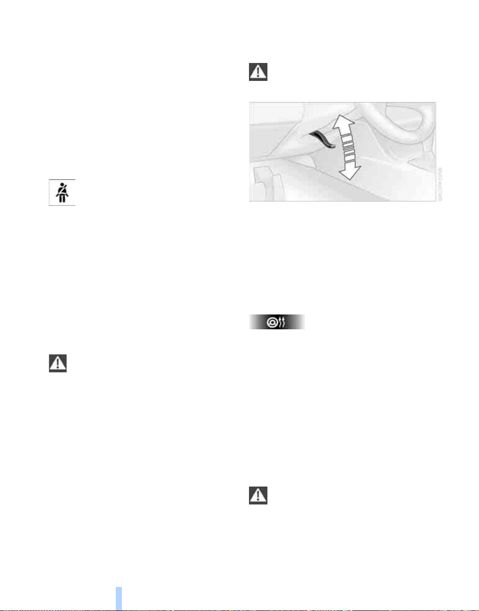
Washer/wiper system/ rain sensor*
0 Wipers retracted
1 Intermittent or rain sensor operation
2 Normal wiper speed
3 Fast wipe
4 Brief wipe
5 Select interval time or set sensitivity of rain
sensor
Fold-out position
The right wiper is partially concealed by the
hood.
To move the wipers into a vertical position:
1. Switch on wipers in lever position 1.
2. When the wipers are approximately vertical,
move the ignition key to position 0.
For changing the wiper blades, refer to page 95.
Fold the wipers back down onto the windshield before you turn the ignition key to
po si tion 1 o r 2 ag ai n. I f y ou do no t, th ey coul d b e
damaged.<
Intermittent mode
Not on vehicles with rain sensor.
You can set the wipe interval to four stages with
the serrated dial 5.
In addition, the wipe interval is varied automatically depending on road speed.
38
Page 40

Rain sensor*
Online Edition for Part-No. 01 41 0 158 448 - © 09/04 BMW AG
The rain sensor automatically controls wiper
operation as a function of the rain intensity. It is
positioned on the windshield, directly in front of
the inside rearview mirror.
Deactivate the rain sensor when passing
through an automatic car wash. Failure to
do so could result in damage caused by undesired wiper activation.<
Activating
As of ignition key position 1 move the lever to
position 1. The wipers travel once across the
windshield, regardless of the weather conditions.
You can leave the lever permanently in position 1 and then only need to activate the rain
sensor as of ignition key position 1. To do so:
> Briefly turn the serrated dial 5 or
> clean the windshield 1, refer to next section
Adjusting sensitivity
Turn the serrated dial 5.
Deactivating
Switch lever to position 0.
Normal wiper speed
The system switches automatically to intermittent mode when the vehicle is not moving, not
on vehicles with rain sensor.
Fast wipe
The wipers operate at normal speed when the
vehicle is not moving, not on vehicles with rain
sensor.
Cleaning windshield, rear window and
headlamps*
0 Wipers retracted
1 Cleaning windshield and headlamps
2 Rear window wiper intermittent mode
3 Cleaning rear window
Do not use the washers if there is any
danger that the fluid will freeze on the
windshield. If you do so, your vision could be
obscured. To avoid freezing, use a washer fluid
antifreeze, refer to page 90. Do not use the
washers when the reservoir is empty. This
could cause damage to the washer pump.<
Cleaning windshield
The system sprays washer fluid against the
windshield and activates the wipers for a brief
period.
The windshield washer nozzles are automatically heated as of ignition key position 2.
Cleaning headlamps*
When the vehicle lighting system is switched
on, the headlamps are cleaned at regular and
appropriate intervals.
Rear window wiper
Rear window wiper in intermittent mode. When
reverse gear is engaged, the wiper operates
continuously.
You can also program the interval:
1. Briefly move the wiper lever from position 0
to position 2.
2. Wait for desired interval; maximum of
30 seconds.
39
Reference At a glanceControlsDriving tipsMobility
Page 41

3. Move the wiper lever from position 0 to
Online Edition for Part-No. 01 41 0 158 448 - © 09/04 BMW AG
position 2 again
To change the wiper blades, refer to page 95.
Maintaining speed, storing, and
accelerating
Driving
Cruise control*
The vehicle maintains and stores the speed
that you set as of a speed of approx. 20 mph/
30 km/h.
You can use cruise control whenever the system is active while the engine is running.
On the sports steering-wheel
for the cruise control are located on the righthand side of the steering wheel.
*
the buttons +/–
Indicator lamp
The indicator lamp lights up green:
System ready for operation using the
buttons on the steering wheel.
Activating system
As of ignition key position 2:
Press button on steering wheel; the indicator
lamp in the instrument cluster comes on. You
are able to use the cruise control.
Do not use the cruise control under unfa-
vorable conditions that do not permit a
constant speed, e.g. when driving on winding
roads or in heavy traffic or when negotiating
poor road conditions such as snow, rain, ice, or
a loose road surface.<
Deactivating system
Briefly press + button:
The system maintains and stores the current
vehicle speed. Every time you briefly press the
button, the vehicle's speed increases by
roughly 1 mph/1 km/h.
+
Press and hold
The vehicle accelerates without pressure on
the accelerator pedal. When you release the
button, the system maintains and stores the
current speed.
If, on a downhill gradient, the engine's
braking effect is not sufficient, the controlled speed can be exceeded. Speed can drop
on uphill grades if the engine output is insufficient.<
button:
Decelerating
Briefly press – button:
Every time you briefly press the button, the
vehicle's speed decreases by roughly 1 mph/
1 km/h provided that you have already activated
the cruise control.
–
Press and hold
With the cruise control active, the system automatically reduces the fuel supply to slow the
vehicle. When you release the button, the system maintains and stores the current speed.
button:
Interrupting cruise control
Press the button repeatedly until the indicator
lamp in the instrument cluster goes out.
The cruise control is also deactivated when the
ignition key is turned to position 0. The speed
stored in the memory is deleted in the process.
40
When the system is activated, press button 1.
The indicator lamp stays on. You can use the
cruise control again whenever required by
requesting the speed that was stored last.
Page 42

In addition, the system is automatically inter-
Online Edition for Part-No. 01 41 0 158 448 - © 09/04 BMW AG
rupted in response to the following conditions:
> When you apply pressure to the brake pedal
> When you apply pressure to the clutch
pedal or when you move the automatic
transmission selector lever from D to N
> If you exceed or fall below the controlled
speed for an extended period, by pressing
the accelerator, for example
> When DSC is activated
Resuming stored speed
Press button:
The vehicle accelerates to and maintains the
last speed stored.
41
Reference At a glanceControlsDriving tipsMobility
Page 43

Everything under control
Online Edition for Part-No. 01 41 0 158 448 - © 09/04 BMW AG
Odometer
1 Odometer
2 Trip odometer
Odometer
Everything under control
You can activate the displays shown in the illustration in ignition key position 0 or with the ignition key removed by pressing the button in the
instrument cluster.
Trip odometer
To reset to zero:
1. Ignition key in position 1.
2. Press and hold the button until the trip
odometer is reset to zero.
Fuel gage
If the indicator lamp 1 starts to light up continuously, there are approx. 2 gallons/8 liters of fuel
in the tank.
Fuel tank capacity:
Approx. 17.7 gallons/67 liters.
If the tilt of the vehicle varies, when you are driving in mountainous areas, for example, the indicator may fluctuate slightly.
Refuel well before the tank is empty, as
otherwise engine functions will not be
ensured and damage can occur if you drive
down to the last drop.<
When you switch on the ignition, the indicator
lamp comes on briefly to confirm that the system is operational.
Tachometer
Engine speeds in the red warning field must
absolutely be avoided.
In this range, the fuel supply is interrupted to
protect the engine.
42
Coolant temperature gage
Blue
The engine is still cold. Drive at moderate
engine and vehicle speeds.
Page 44

Between blue and red fields
Online Edition for Part-No. 01 41 0 158 448 - © 09/04 BMW AG
Normal operating range. It is permissible for the
dial to drift up to the red field.
Red
Comes on while driving:
The engine is overheated. Switch off the engine
immediately and allow it to cool down.
Checking coolant level, refer to page 91.
When you switch on the ignition, the warning
lamp 1 comes on briefly to confirm that the system is operational.
Service Interval Display
Remaining distance until next service
due
The displays shown in the illustration appear for
a few seconds as of ignition key position 1 or
after starting the engine.
Together with the message OIL SERVICE or
INSPECTION, the next scheduled service and
remaining distance to this service are displayed
in miles/kilometers.
The remaining distance is determined on the
basis of the past driving style.
A flashing display and a '– sign' before the
numerical value mean that the service interval
has been passed by the displayed number of
miles/kilometers. Please make an appointment
with your BMW Sports Activity Vehicle Center.
Clock
If you want to have a continuous clock display,
you can also have the time displayed in the display of the car radio, refer to Owner's Manual for
Radio.
You can adjust the clock, also for display in the
radio, as follows.
Setting time
As of ignition key position 1:
Hours
1. Hold button 2 pressed for a few seconds
until the hours are displayed and the colon
flashes.
2. Press button 1 repeatedly until the desired
hour is set.
Minutes
3. Press button 2 to change to the minutes.
4. Press button 1 repeatedly until the desired
minutes are set.
5. Press button 2.
Time is confirmed.
The set time is transferred to the display of the
radio or displayed in the instrument cluster.
Display mode
Ignition key in position 0 or removed:
Press button 1.
The time and display of the miles/kilometers
appear for a few seconds.
43
Reference At a glanceControlsDriving tipsMobility
Page 45

Computer*
Online Edition for Part-No. 01 41 0 158 448 - © 09/04 BMW AG
Mode selection
As of ignition key position 1, you can call up
information from the computer using the computer button in the turn signal lever.
A new function appears each time you briefly
press the computer button.
The displays appear in the following order:
Everything under control
Time, outside temperature, average fuel consumption, cruising range, average speed.
As of ignition key position 1, the last active setting is displayed.
If you desire, you can display the following
functions in a different unit of measure.<
Outside temperature
After an ice warning has been issued, the
display returns to the previous setting.
You can have this activated/deactivated.<
Please bear in mind that the ice warning
does nothing to alter the fact that black
ice may be present on roads at temperatures
higher than +37.57/+36, for instance, on
bridges and shaded roads.<
Clock
12 or 24 hour mode
If your vehicle is equipped with a computer, you
can have the time displayed in the 12 or 24 hour
mode.
During the display, hold down the computer
button in the turn signal lever until the display
changes.
Changing unit of measure 7/6
During the display, hold down the button in the
turn signal lever until the display changes.
Ice warning
If the outside temperature falls below approx.
+37.57/+3 6, the computer switches automatically to the outside temperature display. In
addition, an acoustic signal sounds and the display flashes for a short time.
44
Average fuel consumption
The average fuel consumption is calculated for
the time during which the engine is running.
Reset average consumption: press the computer button in the turn indicator lever for
approx. 2 seconds.
Page 46

Cruising range
Online Edition for Part-No. 01 41 0 158 448 - © 09/04 BMW AG
Displays the estimated cruising range available
with the remaining fuel. The fuel level is measured and the range is calculated taking into
account the driving style over the last 20 miles/
30 km.
Always refuel as soon as possible once
your cruising range falls to below
30 miles/50 kilometers, as otherwise engine
functions are not ensured and damage can
occur.<
Average speed
If you press the computer button for approx.
2 seconds, the currently displayed average
value for speed is recalculated from that
moment onwards.
45
Reference At a glanceControlsDriving tipsMobility
Page 47

Technology for comfort, convenience and
Online Edition for Part-No. 01 41 0 158 448 - © 09/04 BMW AG
safety
PDC Park Distance Control*
The concept
PDC provides extra safety and convenience
during parking maneuvers. Signal tones indicate the current distance to an object behind or
in front of your vehicle. Four ultrasonic sensors
in both the bumpers monitor the distance to the
nearest object.
The front and rear sensors on the corners have
a range of approx. 2 ft/60 cm. The two rear middle sensors have a range of approx. 5 ft/1.50 m
and the two front middle sensors of approx.
2.6 ft/80 cm.
PDC is a parking aid that can indicate
objects when they are approached
slowly, as is usually the case when parking.
Avoid approaching objects too fast, otherwise
the system may give warning of physical obstacles too late.<
If you tow a trailer, the rear sensors cannot take
any practical measurements. Therefore, they
do not switch on.
Automatic mode
In ignition key position 2, the system is automatically activated after approx. one second
each time you shift into reverse or move the
selector-lever into position R. Wait for this short
time span before moving. The system switches
off when you shift out of reverse.
Technology for comfort, convenience and safety
You can have a signal tone programmed
into the system to verify that the PDC is
active.<
Manual mode
In ignition key position 2, press the button; the
indicator lamp lights up.
Deactivating manual mode
Press the button again; the indicator lamp goes
out.
After driving a distance of more than approx.
160 ft/50 m or exceeding a speed of approx.
20 mph/30 km/h, the system switches off and
the indicator lamp goes out. You can reactivate
the system manually as needed.
Signal tones
The distance to an object behind the vehicle is
signaled, in accordance with the position, by an
intermittent tone from a speaker in the rear.
The distance to an object in front of the vehicle
is signaled by an intermittent tone from a loudspeaker beneath the instrument cluster.
As the distance between vehicle and object
decreases, the intervals between the tones
become shorter. The signal tone becomes continuous once the distance to the nearest object
falls to below roughly 1 ft/30 cm.
The signal tone is canceled after approx. 3 seconds when the distance to an object remains
constant during this time, if you are moving parallel to a wall, for instance.
46
Page 48

Malfunction
Online Edition for Part-No. 01 41 0 158 448 - © 09/04 BMW AG
The indicator lamp in the button flashes and a
short continuous tone sounds. PDC is malfunctioning. Switch off PDC. Have the system
checked.
To prevent this problem, keep the sensors
clean and free of ice or snow in order to ensure
that they will continue to operate effectively.
System limits
Even with PDC, final responsibility for
estimating the distance between the
vehicle and any obstructions always remains
with the driver. Even when sensors are involved,
there is a blind spot in which objects cannot be
detected. The system is also subject to the
physical limits that apply to all forms of ultrasonic measurement, such as those encountered with tow bars and trailer couplings, or thin
and wedge-shaped objects etc. Low objects
already displayed, e.g. a curb, can also disappear from the detection area of the sensors
again before a continuous tone sounds.
Loud sources of sound, inside and outside the
vehicle, could drown out the PDC signal tone.<
Keep the sensors clean and free of ice or
snow in order to ensure that they will continue to operate effectively.
Do not apply high pressure spray to the sensors
for a prolonged period of time. Keep the spray at
least 4 in/10 cm away from the sensors.<
Driving stability control systems
Your BMW is equipped with an extended array
of systems designed to enhance and maintain
vehicle stability under extreme conditions.
ABS Antilock Brake System
ABS prevents the wheels from locking during
braking. Safe steering response is maintained
even during full braking. This results in an
increase in the active safety.
ABS is operational every time you start the
engine. Safe braking, refer to page 73.
EBV Electronic brake-force
distribution
EBV controls the brake system's application
pressure in the rear wheels to ensure stable
deceleration.
DBC Dynamic Brake Control
When the brake pedal is depressed quickly, this
system automatically generates a maximal
braking force distribution and thus helps keep
the braking distance to a minimum during full
braking. This system exploits all of the benefits
provided by ABS.
Do not reduce the pressure on the brake pedal
for the duration of the brake application. DBC is
deactivated when you release the brake pedal.
DSC Dynamic Stability Control
DSC prevents slip at the drive wheels when
starting off and accelerating. DSC also detects
unstable driving conditions, such as a fishtailing
of the vehicle's rear end or the sliding of the
vehicle on its front wheels. In these circumstances, DSC helps keep the vehicle on a safe
path, within physical limits, by reducing engine
output and by applying the brakes in individual
wheels.
The DSC is operational every time you start the
engine.
The laws of physics cannot be repealed,
even with DSC. An appropriate driving
style always remains the responsibility of the
driver. Therefore, do not reduce the additional
safety margin again by taking risks.<
Indicator lamp
The indicator lamp goes out shortly
after the engine starts.
When the indicator lamp flashes:
DSC is controlling the drive and braking forces.
When the indicator lamp stays lit:
DSC has been switched off with the button.
47
Reference At a glanceControlsDriving tipsMobility
Page 49

Switching off DSC
Online Edition for Part-No. 01 41 0 158 448 - © 09/04 BMW AG
Reactivating DSC
Press the button; the indicator lamp in the
instrument cluster lights up continuously.
DSC is now deactivated.
Stabilizing interventions of the chassis control
system DSC are no longer available. However,
the braking interventions that simulate the
function of the differential lock continue to be
active.
In the following exceptional circumstances, it
may be useful to switch off DSC for a short
period:
> When rocking the vehicle and starting off in
deep snow or on loose road surfaces
> On sandy road surfaces
> On poor surfaces with deep ruts
> If the wheels spin on muddy surfaces
> When driving with snow chains
As a result of the braking interventions,
the brakes may be subjected to additional
loads when the system is switched off. In order
to limit the brake temperature, brief automatic
suppression of the brake activation is possible.
To maintain vehicle stability, always drive with
the system switched on when possible.<
Technology for comfort, convenience and safety
Press the button again; the indicator lamp in the
instrument cluster goes out. DSC is now activated.
xDrive
xDrive is the all-wheel drive system of your X3.
The combined effects of xDrive and DSC further optimize the traction and dynamic driving
characteristics. The all-wheel drive system
xDrive variably distributes the drive torque to
the front and rear axle depending on the driving
situation and prevailing road conditions.
HDC Hill Descent Control
The concept
HDC is a system for hill descent assistance that
reduces the speed on steep downward inclines
and makes it even easier to control the driving
characteristics of your BMW under these conditions. The vehicle moves at slightly more than
walking speed without active intervention from
the driver.
HDC is available for activation at vehicle speeds
below approx. 20 mph/35 km/h. When driving
down steep hills with a speed below approx.
20 mph/35 km/h, the vehicle reduces speed
automatically down to slightly more than walking speed, approx. 5 mph/8 km/h, and then
maintains this speed at a constant.
You can use the accelerator or brakes to vary
this automatically controlled speed within a
range extending from approx. 3 mph/5 km/h to
15 mph/25 km/h.
You can specify a target speed within the same
range by using the +/– buttons of the cruise
control on the steering wheel.
48
Page 50

Activating system
Online Edition for Part-No. 01 41 0 158 448 - © 09/04 BMW AG
Press the button; the indicator lamp comes on.
The indicator lamp flashes when the brakes are
applied automatically.
Deactivating system
Press the button again; the indicator lamp goes
out.
HDC is deactivated immediately above approx.
35 mph/60 km/h and after approx. 10 seconds
when the ignition is switched off.
Using HDC
In vehicles with manual transmission:
Use HDC in first gear and in reverse gear, as in
the higher gears the engine's braking action
diminishes.
On vehicles with automatic transmission:
You can use HDC in every drive position.
Malfunction
If the indicator lamp in the button goes out in the
HDC mode or fails to light up when the button is
pressed:
HDC is temporarily not available, as the brake
temperature is too high.
Malfunction in vehicle stability control
systems
The warning lamp lights up yellow.
DBC Dynamic Brake Control is defective. Have the system checked as soon
as possible.
Display of the previously described
malfunction on Canadian models.
If one of the malfunctions described
below occurs, proceed cautiously and
defensively. When driving on poor roads, avoid
using the full throttle or kick-down positions of
the accelerator as well as heavy and panic braking. Otherwise the drive train may be damaged
or accidents can occur.<
The red brake warning lamp lights up
together with the warning lamps for
ABS and DSC/xDrive. In addition, a
warning signal sounds. ABS, DSC,
HDC and xDrive have failed. Drive may
then only be carried out via the rear
axle. If the brake warning lamp lights up
yellow in the described combination,
the EBV Electronic brake-force distribution is
still available. Have the system checked as soon
as possible.
Display of the previously described
malfunction on Canadian models.
The warning lamp lights up continu-
ously and a warning signal sounds:
DSC or the xDrive all-wheel system has
failed.
The stabilizing interventions of DSC or the allwheel drive system xDrive are no longer available. It is then possible to exert driving force
only via the rear axle. Have the system checked
as soon as possible.
Flat Tire Monitor
The concept
The Flat Tire Monitor keeps track of the inflation pressures in the four mounted tires as you
drive. The system provides an alert whenever
the inflation pressure drops significantly in relation to the pressure in another tire.
49
Reference At a glanceControlsDriving tipsMobility
Page 51

The check of the tire inflation pressure is based
Online Edition for Part-No. 01 41 0 158 448 - © 09/04 BMW AG
on monitoring the relative speeds of the wheels.
A flat tire is detected and reported on the basis
of a deviation in certain speed ratios.
Functional requirement
So that the Flat Tire Monitor can learn the correct inflation pressure, please perform the following steps:
1. Check the inflation pressures in all tires
2. Compare with the inflation pressure table
on page 83 and correct if necessary
3. Initialize the system.
System limits
The Flat Tire Monitor cannot indicate
sudden severe tire damage caused by
outside factors and does not detect a natural,
even pressure drop in all four tires.<
In the following situations, on the other hand,
there can be delays in detecting tire pressure
losses, and even system failure:
> When driving on snow-covered or slippery
road surfaces.
> In the case of performance-oriented driving:
slip in the drive wheels, high lateral acceleration.
> False alarms and undetected loss of pres-
sure may occur when you are driving with
snow chains fitted.
> When driving with a compact wheel, the Flat
Tire Monitor cannot operate.
Initializing system
Perform the initialization immediately
Technology for comfort, convenience and safety
every time you correct the inflation pres-
sure, change a tire or change a wheel or all
wheels. This requires a trip.<
1. Start the engine, but do not begin to drive.
2. Press the button until the yellow indicator
lamp in the instrument cluster lights up for a
few seconds.
3. Begin driving.
It takes a few minutes until the Flat Tire Monitor
can detect and indicate a flat tire.
Do not initialize the system when driving
with snow chains or with a compact
wheel.<
Indication of a flat tire
The warning lamp lights up yellow.
There is a flat tire or extensive inflation
pressure loss.
1. Reduce speed and stop the vehicle care-
fully. Avoid sudden braking and steering
maneuvers.
2. Identify damaged tire.
If identification is not possible, contact your BMW Sports Activity Vehi-
cle Center.<
3. Replace the damaged wheel, refer to
Changing a wheel on page 99.
Brake Force Display
The Brake Force Display lights up in two
stages, depending on how heavily you brake.
50
Page 52

The display consists of two stages:
Online Edition for Part-No. 01 41 0 158 448 - © 09/04 BMW AG
> Normal braking:
The brake lamps 1 and the center brake
lamp light up.
> Heavy braking and braking with ABS:
The brake lamps 1 and 2 light up together
with the center brake lamp.
Airbags
The following airbags are located beneath the
marked covers:
1 Front airbags for driver and front passenger
2 Head airbags in front and rear
3 Side airbags in front and rear
Protective action
To ensure that the safety systems continue to provide optimal protection,
please follow the instructions on page 24.<
The front airbags help protect the driver and
front passenger by responding to frontal
impacts in which safety belts alone cannot provide adequate restraint. When needed, the
head and side airbags help provide protection in
the event of side impact. The relevant side air-
*
bag supports the side upper body area. The
respective head air bag supports the head.
The airbags are deliberately not triggered in
every impact situation, e.g. less severe accidents, certain roll-over situations or rear-end
collisions.
Labels in the rear door opening should
indicate the status of your rear seat side
airbags. If you are uncertain of their status, or
wish to have the airbags activated or deactivated, please contact your BMW Sports Activity
Vehicle Center.<
For information on the correct sitting position,
refer to page 24.
Do not apply adhesive materials to the
cover panels of the airbags, cover them or
modify them in any other way.
Do not attempt to remove the airbag retention
system from the vehicle. Never modify or
tamper with either the wiring or the individual
components in the airbag system. This category includes the upholstery in the center of the
steering wheel, on the instrument cluster, the
side trim panels on the doors, and the roof pillars along with the sides of the headliner. Do not
attempt to remove or dismantle the steering
wheel.
Do not touch the individual components
directly after the system has been triggered,
because there is a danger of burns. When there
are malfunctions, when deactivating, or after
the triggering of the airbag restraint system,
have the testing, repair, removal, and disposal
of the airbag generators executed only by your
BMW Sports Activity Vehicle Center or at a
workshop that works according to BMW repair
procedures with correspondingly trained personnel and has the required explosives
licenses. Unprofessional attempts to service
the system could lead to failure in an emergency or undesired airbag activation, either of
which could result in personal injury.<
Airbag warning information is also provided on
the sun visors.
51
Reference At a glanceControlsDriving tipsMobility
Page 53

Automatic deactivation of front
Online Edition for Part-No. 01 41 0 158 448 - © 09/04 BMW AG
passenger airbags
Your BMW has a seat occupation detection
system. By evaluating the weight on the front
passenger's seat, the system detects whether
or not the seat is occupied by a child in the
child-restraint system or an adult.
> When a child is seated in the child-restraint
system or with an empty seat, the front and
side airbags are deactivated on the passenger side.
> When an adult is traveling in the front seat,
the front and side airbags remain active on
the passenger side.
Although not desired, it can occur in the
case of heavier children that the front
passenger airbags remain active or in the case
of very light adults or young persons that the
front passenger airbags are deactivated. In
these cases, have the person ride in the rear
seat, refer to Passenger airbag status lamp
below. Do not load the passenger seat with any
items in addition to the person to be transported. Do not fit seat covers, seat cushion padding, ball mats or other items onto the front passenger seat unless they are specifically
re co mm end ed by BMW . D o not pl ace a ny item s
under the seat. Otherwise, the function of the
seat occupation detection could be impaired.<
Operational readiness of airbag system
Technology for comfort, convenience and safety
As of ignition key position 1, the warning lamp
lights up briefly, thus indicating the operational
readiness of the entire airbag system and the
safety belt tensioners.
Airbag system malfunction
> The warning lamp does not light up as of
ignition key position 1.
> The warning lamp lights up continuously.
Have the airbag system checked immedi-
ately if a malfunction occurs, as otherwise
there is a danger of the system failing to
respond in the expected manner to an impact
occurring within its normal response range.<
Passenger airbag status lamp
One of the illustrated indicator lamps is located
above the interior rearview mirror.
The indicator lamp indicates whether the front
passenger airbag system is active or not active/
OFF.
The indicator lamp is used only for the
front passenger airbag system. The indicator lamp illuminates to show that the front
passenger airbag system is OFF/not active.<
> The indicator lamp goes out after a few sec-
onds.
The front passenger airbags are active, e.g.
when transporting an adult.
> The indicator lamp lights up continuously.
The front passenger airbags are deactivated, e.g. when a child is traveling in the
vehicle in the child-restraint system or
when the seat is empty.
Find more information about passenger airbag
system and seat occupancy detection in section Automatic deactivation of front passenger
airbags above.
52
Page 54

Lamps
Online Edition for Part-No. 01 41 0 158 448 - © 09/04 BMW AG
Parking lamps/low beams
Parking lamps
The front, rear and side vehicle lighting
is switched on. You can use the parking
lamps for parking. For lighting on one
side for parking as an additional feature, refer to
page 54.
Low beams
When you switch off the ignition with
the headlamps on, the headlamps go
out and only the parking lamps remain
on.
Lamp defective
The indicator lamp lights up.
At least one bulb of the exterior lighting
on the vehicle is defective.
Replacing bulbs, refer to page 95.
Pathway lighting
When you activate the headlamp flasher after
parking the vehicle and switching off the lamps,
the low beams will come on for a brief period.
You may also have this function deactivated if you wish.<
Lights on warning
If you turn the ignition key to position 0, an
acoustic signal sounds when you open the
driver's door for a few seconds to remind you
that the lights have not yet been switched off
.
Daytime driving lamps*
You can leave the light switch in the second
position: all external lamps go out when you
switch off the ignition.
Always observe all applicable laws governing
the use of daytime driving lamps.
You can switch on the parking lamps when
needed using the standard procedure
described under Parking lamps.
You can have the daytime driving lamps
activated on your vehicle.<
Automatic headlamp control*
When you set the switch to this position, the system activates and switches
on and off the low beams in response to
changes in ambient light conditions, for
instance, in tunnels, at dawn and dusk, and in
rain and snow.
The low beams remain switched on
regardless of the ambient light when you
switch on the front fog lamps.<
Automatic headlamp control cannot
serve as a substitute for the driver's judgment in determining when the vehicle lamps
should be switched on. For example, the system cannot detect fog. To avoid safety risks,
you should always switch on the lamps manually under these conditions.<
You can have the sensitivity of the head-
lamp control adjusted.<
Adaptive Head Light*
The concept
Adaptive Head Light is a variable headlamp
control system that enables better illumination
of the road surface. Depending on the steering
angle and other assumptions, the light from the
headlamp follows the course of the road.
53
Reference At a glanceControlsDriving tipsMobility
Page 55

Activating Adaptive Head Light
Online Edition for Part-No. 01 41 0 158 448 - © 09/04 BMW AG
In ignition key position 2, turn the light
switch to the position Automatic headlamp control, refer to page 53.
To avoid blinding oncoming traffic, the Adaptive
Lamps
Head Light
> is not active when driving in reverse
> i s on ly act iv e t owa rd pass en ger' s s ide wh en
stationary
Fog lamps*
Malfunction
The LED next to the symbol for automatic headlamp control flashes. Adaptive Head Light is
faulty or has failed. Have the system checked as
soon as possible.
High beams/roadside parking lamps
1 High beams
2 Headlamp flasher
3 Roadside parking lamps
Roadside parking lamps, left or right*
You also enjoy the option of lighting up just one
side of your vehicle when parking. When using
this function, comply with national regulations:
In ignition key position 0 or with ignition key
removed:
Move the lever into the corresponding turn signal position.
The roadside parking lamps drain the battery. Avoid using for longer periods, as
otherwise it may not be possible to start the
engine.<
Briefly press the button once again to switch
on/off.
The parking lamps or low beams must
be switched on for the fog lamps to
operate. The green indicator lamp
lights up when the fog lamps are.
If the automatic headlamp control is activated, the low beams will come on auto-
matically when you switch on the fog lamps.<
Instrument lighting
Turn the serrated dial to adjust the illumination
intensity.
54
Page 56

Interior lamps
Online Edition for Part-No. 01 41 0 158 448 - © 09/04 BMW AG
The interior lamps operate automatically.
If you desire, the interior lamps are
switched on after mechanical unlocking
of the vehicle. You may have this function activated/deactivated if you wish.<
If the interior lamps remain switched on
after locking the vehicle, one of the doors
or the tailgate may not be completely closed.<
Switching interior lamps on and off
Briefly press button 1.
If you want the interior lamps to remain off all
the time, press and hold the button for approx.
3seconds.
Press the button briefly to revert to normal
operation.
You can have soft dimming of the interior
lamps set.<
To avoid discharging the battery, all of the
vehicle's interior lamps are automatically
extinguished approx. 15 minutes after the ignition is switched off.<
Front reading lamps*
Switch on and off with buttons 2.
Rear reading lamps*
Switch on and off with the button.
55
Reference At a glanceControlsDriving tipsMobility
Page 57

A congenial climate
Online Edition for Part-No. 01 41 0 158 448 - © 09/04 BMW AG
Air conditioner
A congenial climate
1 Airflow directed toward the windshield and
side windows
2 Airflow for the upper body 57
3 Front footwell ventilation 57
4 Air supply/blower 57
5 Outside air/recirculated-air mode 57
6 Temperature 57
7 Air distribution 57
8 Rear window defroster 57
9 Air conditioner 57
56
Page 58

Air supply/blower
Online Edition for Part-No. 01 41 0 158 448 - © 09/04 BMW AG
You can select blower speeds 1
to 4. The heating and ventilation
become more and more effective
as the air supply settings are
increased. In position 0, the blower
and heater are switched off. The air supply is
blocked in position 0.
Temperature
To increase the temperature of the
interior, turn to the right.
Air distribution
You can direct air to flow onto the
windows , toward the upper
body and into the footwell .
All intermediate settings are possi-
ble. In the setting, there is a
slight flow of air onto the windows to keep them
free of condensation.
Rear window defroster
When the rear window defroster is
activated, the indicator lamp
comes on. The rear window
defroster switches off automatically.
You can have your vehicle programmed in
such a way that the rear window defroster
switches on automatically. It is then switched
on at outside temperatures of less than approx.
+397/+4 6 within 5 minutes of the engine
start.<
Air conditioner
The air is cooled and dehumidified
and warmed again as needed,
depending on the temperature setting. Depending on the weather, the windshield
may fog over briefly when the engine is started.
You can reduce condensation forming on the
windows by switching on the air conditioner.
Condensation forms in the air conditioner
system during operation, and then exits
under the vehicle. Traces of condensed water
under the vehicle are therefore normal.<
Outside air/recirculated-air mode
You can respond to unpleasant
odors outside the vehicle by tem-
porarily switching off the outside
air supply. The system then recirculates the air
currently within the vehicle.
If condensation starts to form on the
inside window surfaces during operation
in the recirculated-air mode, you should switch
it off while also increasing air supply as
required. The recirculated-air mode should not
be used over a sustained period of time, otherwise the air quality inside the vehicle will deteriorate.<
Ventilation
The air vents for the upper body area can be
adjusted:
1 Serrated dials
Serrated dials for opening and closing the
vent outlets through an infinitely-variable
range.
2 Levers
Selector levers for airflow direction.
3 Serrated dial
Use this serrated dial to adjust the amount
of cool air that is added to the airflow
emerging from the vent outlets for the
upper body.
57
Reference At a glanceControlsDriving tipsMobility
Page 59

Ventilation for cooling
Online Edition for Part-No. 01 41 0 158 448 - © 09/04 BMW AG
Adjust the vents to direct the flow of cool air in
your direction, for instance, if the interior has
become too warm.
Draft-free ventilation
Set the vent outlets so that the air flows past
you and is not directed straight at you.
Microfilter
The built-in microfilter removes dust and pollen
from the incoming outside air. It is replaced
when maintenance is performed by your BMW
Sports Activity Vehicle Center. A substantial
reduction in air supply indicates that the filter
A congenial climate
should be replaced before normal maintenance.
Defrosting windows and removing
condensation
1 Rotary blower switch
Set the rotary switch for air supply at level 4.
2 Rotary temperature switch
Turn completely to the right.
3 Rotary switch for air distribution
Turn to position .
4 Rear window defroster
Switch on to defrost the rear window.
58
Page 60

Automatic climate control*
Online Edition for Part-No. 01 41 0 158 448 - © 09/04 BMW AG
1 Airflow directed toward the windshield and
side windows
2 Airflow for the upper body 61
3 Air to footwell 61
4 Individual air distribution 60
5 Temperature 60
6 Temperature display 60
Air supply 60
7 Air supply/blower 60
8 Defrosting windows and removing
condensation 60
9 Rear window defroster 61
10 Air conditioner 60
11 Outside air/AUC Automatic recirculated-air
control/recirculated-air mode 60
12 Automatic air distribution and supply 60
59
Reference At a glanceControlsDriving tipsMobility
Page 61

A congenial climate
Online Edition for Part-No. 01 41 0 158 448 - © 09/04 BMW AG
For almost all conditions, the AUTO program 12 offers the optimal air distribution and
air volume. Select an interior temperature you
find pleasant.
The following section contains more detailed
information on the available setting options.
Your vehicle has been designed to auto-
matically select your personal climatecontrol settings whenever you unlock the doors
using your individually programmed remote
control.<
Automatic air distribution and supply
A congenial climate
lected temperature setting as the basis for
adjusting the interior climate to adapt to external influences: summer, winter.
The cooling is switched on automatically with
the AUTO program.
The AUTO program adjusts the
airflow and distribution patterns for
you while also using your prese-
Individual air distribution
You can cancel the AUTO program
by selecting specific air distribution patterns for your personal
comfort, the automatic air supply
remains in operation. You can
direct air to flow onto the windows , toward the upper body , and into
the footwell . You can reactivate the automatic air distribution mode by selecting the
AUTO button.
Adjusting temperature
The figures in the display provide a
general indication of interior tem-
perature. When you start the vehi-
cle, the AUTO program ensures
that the selected temperature is
achieved as quickly as possible. It
then maintains this temperature, regardless of
the season.
Air supply/blower
You can vary the air supply by
pressing the upper or lower button.
This switches off the automatic
program for the air supply, and the
word AUTO goes out in the dis-
play. The automatic mode for air
distribution remains in operation as before. You
can reactivate the automatic air supply mode by
selecting the AUTO button.
If you press the lower button when at the lowest
blower speed, all displays go out: the blower,
heating and air conditioner are switched off.
The outside air supply is shut off. You can
restart the automatic climate control by pressing any of its buttons.
Defrosting windows and removing
condensation
This program quickly removes ice
and condensation from the wind-
shield and door windows.
Air conditioner
When the air conditioning is on,
the air is cooled, dehumidified,
and then reheated depending on
the temperature setting. Depending on the
weather, the windshield may fog over briefly
when the engine is started. The air conditioner
reduces the formation of condensation on the
windows.
The air conditioner can only operate when the
engine is running and is automatically switched
on with the AUTO program.
Condensation forms in the air conditioner
system during operation, and then exits
under the vehicle. Traces of condensed water
under the vehicle are therefore normal.<
Outside air/AUC Automatic
recirculated-air control/recirculatedair mode
You can respond to unpleasant
odors or pollutants in the immedi-
ate environment by suspending
the supply of outside air. The system then recir-
60
Page 62

culates the air currently within the vehicle.
Online Edition for Part-No. 01 41 0 158 448 - © 09/04 BMW AG
During AUC operation, a sensor detects pollutants in the outside air and controls the shut-off
automatically.
Press the button repeatedly to run through the
following control sequence:
> Indicator lamps off: o utside air flows into th e
vehicle.
> Left indicator lamp on, AUC mode: the sys-
tem recognizes pollutants in the outside air
and blocks the flow of air when necessary.
The system then recirculates the air currently within the vehicle. Depending on the
air quality, the automatic system then
switches back and forth between outside air
supply and recirculation of the air within the
vehicle.
> Right-hand indicator lamp on: the outside
air supply into the vehicle is shut off continuously. The system then recirculates the air
currently within the vehicle.
If condensation starts to form on the
inside window surfaces during operation
in the recirculated-air mode, you should switch
it off while also increasing air supply as
required. The recirculated-air mode should not
be used over a sustained period of time, otherwise the air quality inside the vehicle will deteriorate.<
Ventilation
The air vents for the upper body area can be
adjusted:
1 Serrated dials
Serrated dials for opening and closing the
vent outlets through an infinitely-variable
range.
2 Levers
Selector levers for airflow direction.
3 Serrated dial
Use this serrated dial to adjust the amount
of cool air that is added to the airflow
emerging from the vent outlets for the
upper body.
Ventilation for cooling
Adjust the vents to direct the flow of cool air in
your direction, for instance, if the interior has
become too warm.
Rear window defroster
When the rear window defroster is
activated, the indicator lamp
comes on. The rear window
defroster switches off automatically.
You can have your vehicle set so that the
rear window defroster switches on automatically. It is then switched on at outside temperatures of less than approx. +39 7/+4 6
within 5 minutes of the engine start.<
Draft-free ventilation
Set the vent outlets so that the air flows past
you and is not directed straight at you.
Microfilter/activated-charcoal filter*
The built-in microfilter removes dust and pollen
from the incoming air. The activated-charcoal
filter provides additional protection by filtering
gaseous pollutants from the outside air. This
combined filter is replaced when maintenance
is performed by your BMW Sports Activity Vehicle Center. A substantial reduction in air supply
indicates that the filter should be replaced
before normal maintenance.
61
Reference At a glanceControlsDriving tipsMobility
Page 63

Practical interior accessories
Online Edition for Part-No. 01 41 0 158 448 - © 09/04 BMW AG
Integrated universal remote control*
The concept
The integrated universal remote control
replaces up to three different hand-held transmitters for various items of radio-controlled
equipment such as door openers and house
alarm systems. The integrated universal remote
control recognizes and learns the transmitted
signal of each of the original hand-held transmitters.
The signal of an original hand-held transmitter
can be programmed on one of the three memory buttons 1. Once this is done, each of the
devices can be actuated with the appropriately
programmed memory button 1. The indicator
lamp 2 confirms transmission of the signal.
Practical interior accessories
Should you sell your vehicle one day, be sure to
delete the stored programs beforehand for your
safety, refer to page 63.
To prevent possible damage or injury,
before programming or using the integrated universal remote control, always inspect
the immediate area to make certain that no people, animals or objects are within the travel
range of the device. Also, comply with the
safety precautions of the original hand-held
transmitter.<
Checking compatibility
If you see this symbol on the packaging
or in the manual supplied with the orig-
inal hand-held transmitter, it is safe to
assume that it is compatible with the integrated
universal remote control.
If you have additional questions, please
consult your BMW Sports Activity Vehicle
Center or call 1-800-355-3515.
You can also visit these websites:
www.bmwusa.com or
www.homelink.com.
HomeLink is a registered trademark owned by
Johnson Controls, Inc.<
Programming
1 Memory buttons
2 Indicator lamp
Fixed-code hand-held transmitters
1. Turn the ignition key to position 2.
2. For initial use:
Press both outer buttons 1 for approx.
20 seconds, maintaining pressure until the
indicator lamp 2 starts to flash. The three
memory buttons 1 are cleared.
3. Hold the original hand-held transmitter at a
distance of approx. 2 in/5 cm to 8 in/20 cm
from the memory buttons 1.
The required distance between the
hand-held transmitter and memory
buttons 1 depends on the relevant system
of the original hand-held transmitter used.<
4. Simultaneously press the transmit button
on the original hand-held transmitter and
the desired memory button 1 of the integrated universal remote control. Initially, the
indicator lamp 2 flashes slowly. Release
both buttons as soon as the indicator
lamp 2 flashes rapidly. If the indicator
lamp 2 does not flash rapidly after approx.
15 seconds, change the distance.
5. To program other original hand-held trans-
mitters, repeat steps 3 and 4.
62
Page 64

The corresponding memory button 1 is now
Online Edition for Part-No. 01 41 0 158 448 - © 09/04 BMW AG
programmed with the signal of the original
hand-held transmitter.
You can use the system when the engine is running or when the ignition is switched on.
If the system cannot be operated after
repeated programming, check whether
the original hand-held transmitter uses an alternating-code system. To do so, either read the
instructions of the original hand-held transmitter or press and hold down the programmed
memory button 1 of the integrated universal
remote control. If the indicator lamp 2 on the
integrated universal remote control flashes rapidly for a short time then lights up for approx.
2 seconds, this indicates that the original handheld transmitter uses an alternating-code system. In the case of an alternating-code system,
program the memory buttons 1 as described at
the section on alternating-code transmitters.<
Alternating-code transmitters
Consult the operating instructions of the unit
you wish to set when programming the universal remote control. You will find information
there on the possibilities for synchronization.
When programming hand-held transmitters
that employ an alternating code, please follow
these additional instructions:
Pr ogram min g wi ll be e asi er wit h the a id o f
a second person.<
1. Park your vehicle within the range of the
remote-controlled equipment.
2. Program the integrated universal remote
control as described above at Fixed-code
hand-held transmitters.
3. Locate the button at the receiver of the
equipment to be set, e.g. on the drive.
4. Press the button on the receiver of the
device you want to set up. After step 4, you
have approx. 30 seconds for step 5.
5. Press the programmed memory button 1
of the integrated universal remote control
three times.
The corresponding memory button 1 is now
programmed with the signal of the original
hand-held transmitter.
If you have questions, please contact your
BMW Sports Activity Vehicle Center.<
Clearing memory buttons
Press both outer buttons 1 for approx. 20 seconds until the indicator lamp 2 starts to flash:
all of the memory buttons are cleared.
The memory of individual memory buttons 1
cannot be cleared.
Cup holders
Front
Depending on your optional equipment, the
center console contains either one or two cup
holders.
Passenger side*
The cup holder for the front passenger is
located beneath the air/heating vent.
1. Press the trim piece below the air/heating
vent, arrow.
2. Insert cup.
63
Reference At a glanceControlsDriving tipsMobility
Page 65

Rear
Online Edition for Part-No. 01 41 0 158 448 - © 09/04 BMW AG
Rechargeable flashlight
The flashlight is located on the left side of the
glove compartment. Because it is protected
against overcharging, the flashlight can remain
continually inserted in its holder.
Be sure that the flashlight is switched off
when it is inserted into its holder. Failure
to comply with this precaution could lead to
extreme discharging and damage.<
A cup holder is located in the center armrest at
the rear:
Press the button to open.
Do not place glass containers in the cup
holders, as otherwise there is a danger of
injury in an accident.<
Glove compartment
Opening
Practical interior accessories
Pull the handle. The lamp inside the glove compartment comes on.
Closing
Fold the cover up.
To prevent injury in the event of an accident, close the glove compartment
immediately after use.<
Storage compartments
Armrest, front*
The armrest contains two storage compartments.
> Compartment for CDs:
Press button 1.
> Compartment for coins and miscellaneous
items:
Press button 2.
Armrest, rear
Locking
Use one of the master keys. A master key is also
required for unlocking.
If you only hand over the spare key, e.g. in
a hotel for valet parking, refer to page 16,
the glove compartment cannot be accessed.<
64
The rear armrest contains a storage compartment:
To open, pull the cover upward.
Page 66

Storage compartment in the
Online Edition for Part-No. 01 41 0 158 448 - © 09/04 BMW AG
instrument panel*
Ashtray*
Opening
Press the button in the direction of the arrow.
Closing
Fold the cover down.
Storage package*
Your convenience is enhanced by:
> Armrest, front
> Sliding lashing eyes in cargo area, refer to
page 69
> Floor cover in cargo area that can be used in
two positions, refer to page 69
> Nets in cargo area, on rear side of front seat,
and in passenger footwell
Clothes hooks
When suspending clothing from the
hooks ensure that it will not obstruct the
driver's vision. Do not hang heavy objects on
the hooks. If you do so, they could cause endanger passengers during braking or evasive
maneuvers.<
Press the edge of the opened cover: the ashtray
moves up and can be removed.
On vehicles with the non-smoking package, the
insert is removed in the same way.
Lighter*
Press in the cigarette lighter 1.
The lighter can be removed as soon as it pops
out.
Hold or touch the hot cigarette lighter by
the knob only. Holding or touching it in
other areas could result in burns.
The cigarette lighter remains operational when
the ignition key has been removed. For this reason, do not leave unsupervised children in the
vehicle.<
Power socket
The cigarette lighter socket can be used as a
power socket to plug in hand flashlights, car
vacuum cleaners, etc., with power ratings of up
to approx. 200 W at 12 V. Avoid damage to the
socket caused by inserting plugs of a different
shape or size. With the non-smoker's equipment package the socket is covered with a
removable cap.
65
Reference At a glanceControlsDriving tipsMobility
Page 67

Car phone preparation*
Online Edition for Part-No. 01 41 0 158 448 - © 09/04 BMW AG
Hands-free system
In vehicles with car phone preparation*, the
hands-free microphone is located on the headliner near the interior lamp.
For more information on the car phone, refer to
the Owner's Manual for Telephone.
Ski bag*
The ski bag allows the safe and clean transport
Practical interior accessories
of up to 4 pairs of standard skis or up to two
snowboards.
The ski bag itself plus the additional capacity
provided by the cargo area make it possible to
transport skis with a length of up to 6.9 ft/
2.10 m. When skis of 6.9 ft/2.10 m in length are
loaded the ski bag will tend to narrow, reducing
its overall capacity.
firmly the first time, this also opens the
cover in the cargo area.
3. Place the ski bag between the front seats
and load.
The zipper facilitates access to the stowed
items.
4. Insert the belt tongue of the ski bag retain-
ing belt into the center safety belt buckle.
Make sure to load only clean skis into the ski
bag. Wrap sharp edges so that no damage
occurs.
Securing load
Loading
1. Fold down the center armrest, pull off the
cover, press the button and remove the
cover.
2. Press the button again; the cover in the
cargo area opens. If you press the button
66
After loading, secure the ski bag and its contents. Tension the retaining strap on the tensioning buckle for this purpose.
Secure the ski bag in this way. If you fail to
do so, it could endanger occupants dur-
ing braking or evasive maneuvers.<
To store the ski bag, perform the above steps in
reverse order.
Page 68

Inserting ski bag
Online Edition for Part-No. 01 41 0 158 448 - © 09/04 BMW AG
The ski bag is located in the cargo area under
the floor cover.
1. Fold down the center armrest and pull off
the cover.
2. Remove the tray behind the cover with a
screwdriver by applying it at the application
point in the center of the tray.
3. Position the ski bag on the lower edge of the
opening, refer to arrow 1, then insert it, refer
to arrow 2.
Cargo area
When loading, follow the instructions on
page 74.
Folding rear seat back
Reach into the opening and pull forward, refer
to arrow.
When you fold back the backrest, be sure
that the catch engages securely. Proper
engagement causes the red warning field in the
recess to disappear.<
Removing ski bag
Pull the handle forward and remove the ski bag
upward.
Do not position cargo at the opening. If
you do, it can endanger the passengers
during braking or evasive maneuvers.<
Ski bag*
To create a flat load area floor, you can remove
the ski bag and replace it with a tray before folding the rear backrest forward. The tray is
inserted in the same way as inserting the ski
bag, refer to Inserting ski bag.
Cargo area cover
Pull the cargo area cover out by the handle and
hook it into the rear holders.
You can carry light objects such as articles of
clothing on the cargo area cover.
67
Reference At a glanceControlsDriving tipsMobility
Page 69

Do not place heavy and hard objects on
Online Edition for Part-No. 01 41 0 158 448 - © 09/04 BMW AG
the cover. If you do so, they could endanger occupants during braking maneuvers. Do
not allow the cover to snap back into place, as
otherwise it could be damaged.<
Removal
1. Press the side buttons, refer to arrow 1.
2. Pull the cassette towards the rear, refer to
arrow 2.
Installation
Push the cassette forward into the two side
Practical interior accessories
holders until it locks in place.
Stowing* when rear seat back is folded
down
Partition net*
Hooking partition net into place
Pull the partition net out of the cassette by the
strap. Push together the bar on both sides, refer
to arrows 1, and insert in the brackets. Then
press the bar all the way upward in the middle,
refer to arrow 2, so that it engages in the brackets.
Letting down partition net
Grasp bar on one side on the partition net, press
upward and push together, then release from
the brackets.
Do not allow the partition net to snap back
into place, as otherwise there is a danger
of injury and the partition net could be damaged.<
Holders for the cassette are fitted to the backs
of the rear seat backs, refer to arrows 1.
Guide in the cassette from the right side until it
locks in place, refer to arrow 2. Here, the cargo
area cover must always point in the direction of
travel and the loop of the partition net must
point upward.
You can pull out the partition net and insert it in
the holders in the roof area above.
68
Behind side trim panel
Press the button to open.
Page 70

Floor cover
Online Edition for Part-No. 01 41 0 158 448 - © 09/04 BMW AG
Opening
For access to the jack etc.
To open, raise the cover by the handle, refer to
arrow.
If required, you can remove or raise the floor
cover.
The lashing eyes are located in the cargo area
under the floor cover. They can be inserted at
the openings in the rails. To slide the lashing
eyes, press the button.
Read and comply with the information
enclosed with the load-securing
devices.<
Power socket
Raising
Swing up the floor cover and hook it onto the
handle of the cargo area cover by its catch.
Lashing eyes, rail*
You can secure load-securing devices to the
lashing eyes on the cargo area floor.
Access to power socket:
Fold the cover upward.
The socket can be used to plug in hand flashlights, car vacuum cleaners etc., with power ratings of up to approx. 200 W at 12 V. Do not
damage the socket with unsuitable plugs, also
refer to page 65.
69
Reference At a glanceControlsDriving tipsMobility
Page 71

Online Edition for Part-No. 01 41 0 158 448 - © 09/04 BMW AG
Page 72

Driving tips
Online Edition for Part-No. 01 41 0 158 448 - © 09/04 BMW AG
Driving tips
This section is designed to provide you with
extra support by supplying information
useful in dealing with specific driving
and operating conditions.
Page 73

Things to remember when driving
Online Edition for Part-No. 01 41 0 158 448 - © 09/04 BMW AG
Breaking-in
Moving parts should be allowed to adjust to one
another. To ensure that your vehicle provides
maximum economy throughout a long service
life, we request that you observe the following
instructions.
Engine and differential
Up to 1,200 miles/2,000 km:
Drive at varying engine and driving speeds,
however do not exceed 4,500 rpm or 100 mph/
160 km/h in the process:
Always obey all official speed limits.
Refrain from using full throttle and avoid pressing the accelerator beyond the kick-down point.
Once you have driven 1,200 miles/2,000 km,
the engine and vehicle speeds can be gradually
increased.
Tires
Due to technical factors associated with their
Things to remember when driving
manufacture, tires do not achieve their full traction potential until after an initial break-in
period. For this reason, drive with extra care
during the initial 200 miles/300 km.
Obey your local and state maximum speed limits.
When the vehicle is operated on wet or
slushy roads, a wedge of water may form
between the tire and the road surface. This phenomenon is referred to as hydroplaning and can
lead to partial or complete loss of traction, vehicle control and braking effectiveness. Reduce
your speed on wet roads.<
Brake system
Approx. 300 miles/500 km must elapse before
the brake pads and rotors achieve the optimal
pad-surface and wear patterns required for
trouble-free operation and long service life later
on.
To break in the separate handbrake drums,
apply the handbrake lightly when coasting to a
stop – at a traffic signal, for instance; use caution to avoid posing a danger to other road
users.
To avoid corrosion, repeat this procedure from
time to time.
The brake lamps do not come on when the
handbrake is applied.
Vacuum for the brake system servo unit
on your BMW is available only when the
engine is running. When you move the vehicle
with the engine off – e.g. by towing – substantially higher levels of pedal force will be required
to brake the vehicle.<
Clutch
The function of the clutch is also only at its optimized level after a distance driven of approx.
300 miles/500 km. During this break-in period,
engage the clutch gently.
Following component replacements
Observe the break-in instructions again if previously addressed components must be replaced
again during driving later.
General driving notes
Closing tailgate
Operate the vehicle only when the tail-
gate is completely closed, as otherwise
exhaust fumes could enter the interior of the
vehicle.<
If special circumstances should make it absolutely necessary to operate the vehicle with the
tailgate open:
1. Close all windows and the panorama glass
sunroof.
2. Greatly increase the air supply of the air
conditioner or automatic climate control,
refer to page 56 or 59.
72
Page 74

Hot exhaust system
Online Edition for Part-No. 01 41 0 158 448 - © 09/04 BMW AG
As in all vehicles equipped with a catalytic
converter, extremely high temperatures
are generated in this vehicle. Do not remove the
heat shields installed adjacent to various sections of the exhaust system, and never apply
undercoating to them. When driving, standing
at idle and while parking take care to avoid possible contact between the hot exhaust system
and any highly flammable materials such as hay,
leaves, grass, etc. Such contact could lead to
a fire, resulting in serious personal injury and
property damage.<
When the vehicle is parked
Condensation forms in the air conditioner system during operation, and then exits under the
vehicle. Traces of condensed water under the
vehicle are thus normal.
Before driving into a car wash
Fold in the exterior mirrors, refer to page 28, as
otherwise they could be damaged due to the
width of the vehicle.
Deactivate the rain sensor as otherwise damage could result from undesired wiper activation, refer to page 39.
Mobile communications devices in
vehicle
BMW does not recommend using mobile
communications devices, e.g. portable
phones, in the interior of the vehicle without a
direct connection to an outside antenna. Otherwise the vehicle electronics and mobile communications device can affect each other. In
addition, there is no assurance that the radiation which results during transmission will be
dissipated from the vehicle interior.<
Inside rearview mirror, automatically
dimming*
The inside rearview mirror contains two photocells that control the automatic dimming function. One is integrated into the mirror glass, the
other is located on the back of the mirror.
For trouble-free operation, keep the photocells
clean and do not cover the area between the
interior rearview mirror and the windshield. Do
not attach any kind of stickers on the windshield
in front of the mirror, either.
Hydroplaning
When driving on wet or slushy roads,
reduce road speed. If you do not, a wedge
of water can form between tires and road surface. This phenomenon is referred to as hydroplaning, and is characterized by a partial or
complete loss of contact between tires and
road surface, ultimately undermining your ability to steer and brake the vehicle.<
Driving through water
Do not drive through water on the road if it
is deeper than 20 in/50 cm, and then only
at walking speed. Otherwise, the vehicle's
engine, the electrical systems and the transmission may be damaged.<
Use handbrake on inclines
Do not hold the vehicle in place on slopes
by slipping or riding the clutch, use the
handbrake instead. Otherwise greater clutch
wear will result.<
Safe braking
Your BMW is equipped with ABS as standard
equipment. The best way to brake is to apply
maximum pressure to the brake pedal during
emergency: panic braking. Since the vehicle
maintains steering responsiveness, you can
nevertheless avoid possible obstacles with a
minimum of steering effort.
73
Reference At a glanceControlsDriving tipsMobility
Page 75

Pulsation at the brake pedal combined with
Online Edition for Part-No. 01 41 0 158 448 - © 09/04 BMW AG
sounds from the hydraulic circuits indicates to
the driver that ABS is in its active mode.
Wet roads
While driving in wet conditions and in heavy
rain, it is a good idea to apply light pressure to
the brake pedal every few miles. Watch traffic
conditions to ensure that this maneuver does
not endanger other road users. The heat which
is generated by the brake applications helps to
dry the brake pads and rotors. The full braking
force will then be available when you need it.
Hills
To prevent overheating and reduced effi-
ciency of the brake system, drive long or
steep downhill gradients in the gear in which
the least braking is required. Otherwise, even
light but consistent pedal pressure can lead to
high temperatures, brake wear and possibly
even brake failure.<
You can further enhance the engine's braking
effect by selecting a lower gear in the automatic
transmission's manual mode, downshifting as
far as first gear on extremely steep stretches,
Things to remember when driving
refer to page 37. This strategy helps you avoid
placing excessive loads on the brake system.
During slower downhill driving, use the HDC Hill
Descent Control, refer to page 48.
Never drive with the clutch engaged, the
transmission in Neutral or with the engine
switched off, as otherwise there is no engine
braking when the transmission is in neutral, and
no power-assist for brakes and steering with
the engine switched off.
Never allow floor mats, carpets or other objects
to protrude into the area around the brake or
accelerator pedals and obstruct their movement.<
Corrosion on brake rotors
When the vehicle is driven only occasionally,
during extended periods when the vehicle is not
used at all, and in operating conditions where
brake applications are less frequent, there is an
increased tendency for corrosion to form on
rotors, while contaminants accumulate on the
brake pads. This occurs because the minimal
pressure which must be exerted by the pads
during brake applications to clean the rotors is
not reached.
Should corrosion form on the brake rotors, the
brakes will tend to respond with a pulsating
effect that even extended application will fail to
cure.
Cargo loading
To avoid loading the tires beyond their
approved carrying capacity, never overload the vehicle. Overloading can lead to overheating and increases the rate at which damage
develops inside the tires. The ultimate result
can assume the form of a sudden air loss.<
Determining load limit
1. Locate the following statement on your
*
vehicle's placard
The combined weight of occupants
and cargo should never exceed
XXX Ibs. or YYY kg, as otherwise the vehicle
may be damaged and unstable driving conditions may result.<
2. Determine the combined weight of the
driver and passengers that will be riding in
your vehicle.
:
74
Page 76

3. Subtract the combined weight of the driver
Online Edition for Part-No. 01 41 0 158 448 - © 09/04 BMW AG
and passengers from XXX lbs. or YYY kg.
4. The resulting figure equals the available
amount of cargo and luggage load capacity.
For example, if the XXX amount equals
990 lbs. and there will be five 150-lbs. passengers in your vehicle, the amount of available cargo and luggage load capacity is
240 lbs.:
990 lbs. minus 750 lbs. = 240 lbs.
5. Determine the combined weight of luggage
and cargo being loaded on the vehicle. That
weight may not safely exceed the available
cargo and luggage load capacity calculated
in step 4.
6. If your vehicle will be towing a trailer, part of
the load from your trailer will be transferred
to your vehicle. Consult the manual for
transporting a trailer to determine how this
may reduce the available cargo and luggage
load capacity of your vehicle.
Load
The permitted load is the total of the weight of
occupants and cargo/luggage. The greater the
weight of occupants, the less cargo/luggage
can be transported.
Stowing cargo
> Load heavy cargo as far forward and as low
as possible, placing it directly behind the
bulkhead behind the rear seats.
> Cover sharp edges and corners.
> Pull out the partition net, refer to page 68,
making sure that objects cannot penetrate
the partition net.
> Do not stack cargo higher than the upper
edge of the backrests.
> Items that could bump against the rear win-
dow while driving must be adequately covered.
> For very heavy cargo when the rear seat is
not occupied, secure each safety belt in the
opposite buckle.
Securing cargo
> Use the luggage net* to hold down small
and lightweight luggage and cargo, refer to
page 68.
> For larger and heavier pieces, heavy-duty
cargo straps* are available from your BMW
Sports Activity Vehicle Center. Lashing
eyes for attaching these heavy-duty cargo
straps have been provided in your vehicle's
cargo area, refer to page 69.
75
Reference At a glanceControlsDriving tipsMobility
Page 77

> Read and comply with the information
Online Edition for Part-No. 01 41 0 158 448 - © 09/04 BMW AG
enclosed with the heavy-duty cargo straps.
Always position and secure the load as
described above. If you do not, it can even
endanger the passengers during braking or
evasive maneuvers.
Never exceed either the approved gross vehicle
weight or either of the approved axle loads, refer
to page 112, as excessive loads can pose a
safety hazard, and may also place you in violation of freeway safety laws.
You should never transport heavy or hard
objects unsecured in the passenger compartment, as they could fly around and pose a safety
hazard to the vehicle's occupants during abrupt
braking or evasive maneuvers.<
Roof-mounted luggage rack*
A special rack system is available as a optional
accessory for your BMW. Please observe the
information contained in the installation instructions.
Loading luggage rack
Things to remember when driving
Because roof racks raise the vehicle's center of
gravity when loaded, th ey have a major e ffect on
its handling and steering response. You should
therefore always remember not to exceed the
approved roof weight, the approved gross vehicle weight or the axle loads when loading the
rack.
You can find the specified weights in the Technical data section on page 112.
Make sure that the load is evenly distributed,
and that it does not extend outward to beyond
the limits of the loading surface. Always load the
heaviest pieces first – on the bottom. Be sure
that adequate clearance is maintained for raising the glass sunroof, and that objects do not
project into the opening path of the tailgate.
Secure roof-mounted cargo correctly and
securely to prevent it from shifting or being lost
during the trip.
Drive smoothly. Avoid sudden acceleration and
braking maneuvers. Take corners gently.
Driving on poor roads
Your X3 is at home on all paved and unpaved
roads. It combines all-wheel drive with the
advantages of a normal passenger car.
Driving on unpaved terrain can cause
damage to the vehicle.<
When you are driving on poor roads, there are a
few points which you should strictly observe –
for your own safety, for that of your passengers,
and for the safety of the vehicle:
> Familiarize yourself with the vehicle before
you begin driving. Do not take risks with the
vehicle under any circumstances.
> Always adapt the driving speed to the road
conditions. The more steep and uneven the
roadway is, the lower the speed should be.
> You can operate your vehicle on uphill and
downhill gradients with a maximum slope of
50%. If you wish to drive on uphill and
downhill grades of this nature, make sure
beforehand that the engine oil and coolant
levels are near the MAX mark, refer to
pages 90 and 91.
> For very steep downhill driving, use HDC
Hill Descent Control, refer to page 48. It is
possible to start off on upward inclines of up
to 32%.
The permitted side tilt is 32%.
> While driving, watch carefully for obstacles
such as rocks or holes. Try to avoid these
obstacles whenever possible.
> Avoid that the body makes contact with the
ground, e.g. on the crests of hills and bumpy
roads. The ground clearance of the vehicle
is a maximum of approx. 8.0 in/20 cm.
Please be aware that the ground clearance
can vary depending on the load and operating conditions of the vehicle.
> Do not drive in water that is deeper than
20 in/50 cm. If you must drive through water
up to that depth, drive at a walking speed
and do not stop.
After leaving the water, press on the footbrake gently several times while driving at a
low speed. The brake applications will help
76
Page 78

to dry the brakes, thus preventing a reduc-
Online Edition for Part-No. 01 41 0 158 448 - © 09/04 BMW AG
tion in braking performance caused by the
moisture.
For cleaning the handbrake, apply the lever
slightly at approx. 25 mph/40 km/h and continue to drive for approx. 200 yards/
200 meters, provided that traffic conditions
allow you to do so.
Please bear the following points in mind after
driving on poor roads, in order to preserve the
road safety of your BMW:
> Clean the heavy dirt from the body.
> Clean mud, snow, ice and other materials
from the wheels and tires. Check the tires
for damage.
77
Reference At a glanceControlsDriving tipsMobility
Page 79

Online Edition for Part-No. 01 41 0 158 448 - © 09/04 BMW AG
Page 80

Mobility
Online Edition for Part-No. 01 41 0 158 448 - © 09/04 BMW AG
Mobility
This section helps you maintain your mobility
by supplying important information on
vital topics including fuels and lubricants,
wheels and tires, service, maintenance
and breakdown assistance.
Page 81

Refueling
Online Edition for Part-No. 01 41 0 158 448 - © 09/04 BMW AG
Fuel filler door
Refueling
Always switch off the engine before refu-
eling, as it is not possible to add fuel with
the engine running, and attempts to do so may
also trigger the Service Engine Soon lamp.<
To open and close: press the rear edge of the
fuel filler door.
Manual release
Observe the following when refueling
When handling fuels, comply with all of
the applicable safety precautions posted
at the service station.<
Put the filler cap in the bracket attached to the
fuel filler door.
When refueling, insert the filler nozzle completely into the filler pipe. Lifting the filler nozzle
during refueling
> results in premature pump shutoff
> can lead to reduced efficiency in the fuel-
vapor recovery system
The fuel tank is full when the filler nozzle clicks
off the first time.
In the event of an electrical malfunction in the
system, you can release the fuel filler door manually:
1. Open the cover flap in the cargo area on the
right-hand side panel, refer to page 68.
2. Pull the green button.
Always observe all applicable precautions
and regulations when handling fuels.
Never carry spare fuel containers in your vehicle. Whether empty or full, these containers can
leak, cause an explosion, and lead to fire in the
event of a collision.<
80
Closing fuel filler cap
Fit the cap and turn it clockwise until you clearly
hear a click.
Close the filler cap carefully after refueling
until a click is heard. While closing, be
sure not to squeeze the strap which is fastened
to the cap. A loose or missing cap will activate
*
the Check gas cap lamp
The warning lamp
The fuel filler cap is not properly closed
or is missing. Check whether the fuel
filler cap is properly closed.
.<
*
lights up.
Fuel tank capacity
Approx. 17.7 gallons/67 liters, including the
reserve capacity of approx. 2 gallons/8 liters.
Page 82

Never attempt to continue driving until
Online Edition for Part-No. 01 41 0 158 448 - © 09/04 BMW AG
the tank is completely empty, as engine
functions could be affected, and the vehicle
could sustain damage as a result.<
Fuel specifications
The engine uses unleaded gasoline only.
Required fuel
Premium unleaded gasoline,
minimum octane rating: 91.
Minimum octane rating corresponds to the
Anti Knock Index AKI and is determined to the
so-called (R+M)/2 method.
Do not use leaded gasoline, as otherwise
the lambda probe and catalytic converter
will be permanently damaged.<
Use high-quality brands
Field experience has indicated significant differences in fuel quality: volatility, composition,
additives, etc., among gasolines offered for sale
in the United States and Canada. Fuels containing up to and including 10% ethanol or other
oxygenates with up to 2.8% oxygen by weight,
that is, 15% MTBE or 3% methanol plus an
equivalent amount of co-solvent, will not void
the applicable warranties with respect to
defects in materials or workmanship.
The use of poor-quality fuels may result in
drivability, starting and stalling problems
especially under certain environmental conditions such as high ambient temperature and
high altitude.
Should you encounter drivability problems
which you suspect could be related to the fuel
you are using, we recommend that you respond
by switching to a recognized high-quality
brand. Failure to comply with these recommendations may also result in unscheduled maintenance.<
81
Reference At a glanceControlsDriving tipsMobility
Page 83

Wheels and tires
Online Edition for Part-No. 01 41 0 158 448 - © 09/04 BMW AG
Tire inflation pressure
Information for your safety
It is not merely the tire's service life, but also
driving comfort and – to a great extent – driving
safety that depend on the condition of the tires
and the maintenance of the specified tire pressure.
Wheels and tires
Checking pressure
Only check tire inflation pressure when the tires
are cold, i.e. after a maximum of 1.25 miles/2 km
driving or when the vehicle has been parked for
at least 2 hours. When tires are warm, the tire
inflation pressure increases.
Check the tire inflation pressure regularly
and correct it if necessary, including compact wheel: at least every two weeks and before
beginning a longer trip. If you fail to observe this
precaution you may be driving on tires with
incorrect tire pressures, a condition that can not
only comprom ise your vehicle's driving stabi lity,
but also lead to tire damage and the risk of an
accident. Do not drive with a depressurized, i.e.
flat tire. A flat tire will seriously impair your vehicle's handling and braking response. Attempts
to drive on a flat tire can lead to loss of control
over the vehicle.<
After correcting the inflation pressure(s),
always reinitialize the Flat Tire Monitor,
refer to page 50.<
Inflation pressures for factory-installed
tires
The inflation pressures for your factoryinstalled tires can be found on the door jamb
when you open the driver's door.
Inflation pressures for other tire sizes
The table below provides all the correct inflation
pressures for the specified tire sizes at ambient
temperature.
For correct identification of the right tire
inflation pressure for your tires, observe
the specifications for the corresponding tire
sizes.<
Tire size
The inflation pressures apply to the tire sizes
approved and tire brands recommended by
BMW; a list of these is available from your
BMW Sports Activity Vehicle Center.
82
Page 84

X3 2.5i/3.0i
Online Edition for Part-No. 01 41 0 158 448 - © 09/04 BMW AG
Tire size Pressure specifications in psi/kPa
All pressure specifications in the table
are indicated in psi/
kilopascal with cold tires,
cold = ambient temperature
235/55 R 17 99 H M+S
29/200 32/220 32/220 38/260
235/55 R 17 99 Q, T, H M+S
215/60 R 17 96 H M+S
32/220 35/240 35/240 41/280
215/60 R 17 96 Q, T, H M+S
235/50 R 18 97 H M+S
235/50 R 18 97 V
Front: 235/50 R 18 97 V
Rear: 255/45 R 18 99 V
Front: 235/45 R 19 95W
Rear: 255/40 R 19 96W
32/220
–
32/220
–
–
32/220
–
35/240
35/240
35/240
Compact wheel: T 135/90 R 17 104 M 61/420
More details on the permitted load and weights can be found on page 112
–
–
38/260
–
–
41/280
83
Reference At a glanceControlsDriving tipsMobility
Page 85

Tire identification marks
Online Edition for Part-No. 01 41 0 158 448 - © 09/04 BMW AG
Knowledge of the labeling on the side of the tire
makes it easier to identify and choose the right
tires.
Tire size
e.g. 235/50 R 18 97 V
Nominal width in mm
Cross-sectional
relationship in Ξ
Radial tire code
Wheels and tires
Rim diameter in inches
Load rating,
not for ZR tires
Speed rating,
before R on ZR tires
Speed code letter
Q = up to 105 mph/160 km/h
T = up to 118 mph/190 km/h
H = up to 131 mph/210 km/h
V = up to 150 mph/240 km/h
W = up to 167 mph/270 km/h
Y = up to 186 mph/300 km/h
Tire Identification Number
Tires with DOT codes meet the guidelines of
the U.S. Department of Transport.
DOT code:
e.g. DOT xxxx xxx 3603
Manufacturer code
for tire make
Tire size and tire design
Tire age
Tire age
The tire's date of manufacture is indicated on
the sidewall:
DOT ... 3004 indicates that a tire was manufactured in week 30 of the year 2004.
BMW recommends that you replace all tires
after 6 years at most, even if some tires may last
for 10 years.
Uniform Tire Quality Grading
Quality grades can be found where applicable
on the tire sidewall between tread shoulder and
maximum section width.
For example:
Tread wear 200 Traction AA
Temperature A
DOT Quality Grades
Tread wear
Traction AA A B C
Temperature A B C
All passenger car tires must conform to
Federal Safety Requirements in addition
to these grades.<
Tread wear
The tread wear grade is a comparative rating
based on the wear rate of the tire when tested
under controlled conditions on a specified government test course.
For example, a tire graded 150 would wear one
and one-half, 1γ, times as well on the government course as a tire graded 100. The relative
performance of tires depends upon the actual
conditions of their use, however, and may
depart significantly from the norm due to variations in driving habits, service practices and differences in road characteristics and climate.
Traction
The traction grades, from highest to lowest, are
AA, A, B, and C.
Those grades represent the tire's ability to stop
on wet pavement as measured under controlled
conditions on specified government test surfaces of asphalt and concrete. A tire marked C
may have poor traction performance.
The traction grade assigned to this tire is
based on straight-ahead braking traction
tests, and does not include acceleration, cornering, hydroplaning, or peak traction characteristics.<
84
Page 86

Temperature
Online Edition for Part-No. 01 41 0 158 448 - © 09/04 BMW AG
The temperature grades are A, the highest, B
and C, representing the tire's resistance to the
generation of heat and its ability to dissipate
heat when tested under controlled conditions
on a specified indoor laboratory test wheel.
Sustained high temperature can cause the
material of the tire to degenerate and reduce
tire life, and excessive temperature can lead to
sudden tire failure. The grade C corresponds to
a level of performance which all passenger car
tires must meet under the Federal Motor Vehicle Safety Standard No. 109. Grades B and A
represent higher levels of performance on the
laboratory test wheel than the minimum
required by law.
The temperature grade for this tire is
established for a tire that is properly
inflated and not overloaded. Excessive speed,
underinflation, or excessive loading, either separately or in combination, can cause heat
buildup and possible tire failure.<
M+S
Winter and all-season tires.
These have better winter properties than summer tires.
Tire condition
Inspect your tires frequently for tread wear,
signs of damage and for foreign objects lodged
in the tread. Check the tread pattern depth.
Tire tread
The tread depth should not drop below 0.12 in/
3 mm, although, for example, European legislation only specifies a minimum tread depth of
0.063 in/1.6 mm.
At tread depths below 0.12 in/3 mm, there is an
increased risk of high-speed hydroplaning,
even when only small amounts of water are
present on the road surface. As winter tires display a noti ceable loss in their a bility to cope with
cold-weather driving conditions once the tread
wears to below 0.16 in/4 mm, to ensure contin-
ued safety you should always have such tires
replaced.
Wear indicators at the tread-groove base, refer
to arrow, are distributed over the tire's circumference and are marked on the side of the tire
with TWI – Tread Wear Indicator. At a tread
depth of 0.063 in/1.6 mm these indicators, signal that the tires have reached the legally permissible wear limit.
Wheel/tire damage
Due to low-profile tires, please note that
wheels, tires and suspension parts are
more susceptible to road hazard and consequential damages.<
Unusual vibrations encountered during normal
vehicle operation can indicate tire failure or
some other vehicle defect. This can, for example, be caused by driving over curbs. These
kinds of problems may also be signaled by other
changes in vehicle response, such as a strong
tendency to pull to the left or right.
In these cases reduce speed immedi-
ately. Drive carefully to the next BMW
Sports Activity Vehicle Center or tire dealer, or
have the vehicle towed to one of these locations
if necessary.
Tire damage, extending to sudden and complete loss of pressure in extreme cases, can
pose a potentially lethal safety hazard for the
vehicle's occupants and other road users
alike.<
85
Reference At a glanceControlsDriving tipsMobility
Page 87

New wheels and tires
Online Edition for Part-No. 01 41 0 158 448 - © 09/04 BMW AG
Have new wheels and tires installed only
by your BMW Sports Activity Vehicle
Center or tire shop that works according to
BMW repair procedures with correspondingly
trained personnel. If this work is not carried out
properly, there is a danger of subsequent damage and related safety hazards.<
Retreaded tires
BMW does not recommend the use of
Wheels and tires
retreaded tires, as otherwise driving
safety may be reduced. The causes for this
include the possibly different tire casing structures and the often wide variations in their age,
which can result in a limited service life.<
The right wheels and tires
BMW recommends that you use only
wheel and tire combinations that BMW
has tested and approved for your particular
vehicle. Variations in factors such as manufacturing tolerances mean that even wheels and
tires with identical official size ratings could
actually have different dimensions than the
approved units – these differences could lead to
body contact, and with it the risk of severe accidents. If non-approved wheels and tires are
used, BMW cannot evaluate their suitability,
and therefore cannot be held liable for driving
safety.<
You can ask your BMW Sports Activity Vehicle
Center for the correct wheel-and-tire combination.
The correct wheel-and-tire combination affects
various systems whose function would otherwise be impaired, e.g. ABS, DSC or xDrive.
To maintain good handling and vehicle
response, use only tires of a single tread configuration from a single manufacturer. After a flat
tire, always remember to have the specified
wheel-and-tire combination remounted on the
vehicle as soon as possible.
Recommended tire sizes and brands
BMW tests certain tire brands for each tire size,
classifies them as road-safe and approves
them. These are available at a specialized
dealer, preferably your BMW Sports Activity
Vehicle Center. Observe any country-specific
regulations, e.g. on making a corresponding
entry in the vehicle documents.
The factory-mounted tires have been specially
selected to provide optimized performance
when installed on your vehicle; if properly cared
for, they will provide a combination o f safety and
excellent ride comfort.
Special characteristics of winter tires
BMW recommends winter tires for use in cold
winter driving conditions. Although all-season
M+S tires provide better winter traction than
summer tires, they generally fail to provide the
same levels of cold-weather performance as
winter tires.
Observing speed ratings
Never exceed the maximum speed for
which the winter tires are rated. Unprofessional attempts by laymen to service tires
can lead to damage and accidents. Have this
work performed by skilled professionals only.
The technicians at your BMW Sports Activity
Veh ic le C en te r wi ll be gl ad to a ss ist yo u wit h t he
required professional knowledge and specialized equipment.<
Storage
Store wheels or tires in a cool, dry place, protecting them against light whenever possible.
Protect the tires against contact with oil, grease
and fuel. Do not exceed the maximum tire inflation pressure indicated on the side wall of the
tire.
86
Page 88

Snow chains*
Online Edition for Part-No. 01 41 0 158 448 - © 09/04 BMW AG
Only certain snow chains have been tested by
BMW and classified and approved as safe. You
can obtain a list of these from your BMW Sports
Activity Vehicle Center. BMW recommends the
use of approved narrow-link snow chains only.
These snow chains are approved exclusively for
use on summer or winter tires in pairs on the
rear wheels.
Observe the manufacturer's instructions when
installing snow chains.
Do not exceed a vehicle speed of 30 mph/
50 km/h with snow chains mounted.
Snow chains may not be mounted on the following tires:
> 255/45 R 18
> 255/40 R 19
After mounting snow chains, do not ini-
tialize the Flat Tire Monitor.
When you are driving with snow chains, it can
be beneficial to switch off DSC briefly, refer to
page 48.<
87
Reference At a glanceControlsDriving tipsMobility
Page 89

Under the hood
Online Edition for Part-No. 01 41 0 158 448 - © 09/04 BMW AG
Never attempt to perform any service or
repair operations on your vehicle without
the required professional technical training. If
you are not familiar with the regulations to be
observed, have work on your vehicle carried out
only by a BMW Sports Activity Vehicle Center
or a workshop that uses personnel trained in
accordance with BMW requirements. If this
work is not carried out properly, there is a dan-
Under the hood
ger of subsequent damage and related safety
hazards.<
Hood
Unlocking
Pull the lever located under the left side of the
instrument cluster.
Closing
Let the hood fall from approx. 1 ft/30 cm so that
you hear it engage.
Observe the same precautions that apply
to all closing operations by ensuring that
the hood's travel range is clear and unobstructed before allowing the hood to fall into
position.
If you see any signs that the hood is not completely closed while driving your vehicle, you
should stop at once and close it securely.<
Opening
Press the release handle and open the hood.
88
Page 90

Engine compartment
Online Edition for Part-No. 01 41 0 158 448 - © 09/04 BMW AG
1 Reservoir for windshield and headlamp
washer system 90
2 Body ground: negative terminal 104
3 Auxiliary terminal for jump starting 104
4 Engine oil filler neck 91
5 Brake fluid reservoir 92
6 Dipstick for engine oil 90
7 Coolant expansion tank 91
89
Reference At a glanceControlsDriving tipsMobility
Page 91

Washer fluid
Online Edition for Part-No. 01 41 0 158 448 - © 09/04 BMW AG
Headlamp* and windshield washer
system
The antifreeze for the washer systems is
flammable. For this reason, keep it away
from sources of flame and store it only in its
original containers. Store it so that it is inaccessible to children. Always observe the instructions for use provided on the containers.<
We recommend that you mix the washer
Under the hood
fluid before adding it to the reservoir.<
Capacity of the windshield washer system:
approx. 3.2 US quarts/3 liters.
Capacity for equipment with headlamp washer
system: approx. 6.9 US quarts/6.5 liters.
Fill with water and, if required, with an antifreeze
additive according to manufacturer's recommendations.
Engine oil
Engine oil consumption depends on driving
style and operating conditions.
Engine oil level
The warning lamp lights up yellow while
driving:
The oil level is at the absolute minimum. Add engine oil as soon as possible. Until
then, do not drive more than approx. 30 miles/
50 km.
The warning lamp lights up yellow after
the engine is switched off:
Top off engine oil at the earliest opportunity, e.g. when refueling.
Engine oil sensor
The warning lamp lights up yellow
within 20 seconds after starting the
engine:
The oil level sensor is defective. Have checked
as soon as possible.
Checking oil level
1. With the engine at operating temperature,
i.e. after at least 6 miles/10 km of uninterrupted driving, park the vehicle in a horizontal position.
2. Switch off engine.
3. After approx. 5 minutes, pull the dipstick out
and wipe it off with a clean lint-free. cloth,
paper towel, or similar material.
4. Carefully push the dipstick all the way into
the guide tube and pull it out again.
The oil should extend to between the two
marks on the dipstick.
Warning lamp
Engine oil pressure
The warning lamp lights up red:
Stop the vehicle immediately and
switch off the engine. Check the engine
oil level; top off as required. If the oil level is correct: have the system checked immediately.
Do not continue driving. The engine could
be damaged because of inadequate lubri-
cation.<
90
5. Push the oil dipstick into the dipstick tube
as far as possible again.
The oil quantity between the two marks of the
dipstick is approx. 1.1 US quarts/1 liter.
Page 92

Do not fill beyond the upper mark on the
Online Edition for Part-No. 01 41 0 158 448 - © 09/04 BMW AG
dipstick. Excess oil can damage the
engine.<
Adding engine oil
Do not add oil until the oil level has dropped to
just above the lower marking on the dipstick,
refer to page 90.
Add oil within the next 30 miles/50 km,
otherwise engine damage could result.<
Store oil, grease etc., well out of the reach
of children; always observe all warning
labels on the containers.<
Oil change
Have oil changed only at your BMW Sports
Activity Vehicle Center or at a workshop that
works according to BMW repair procedures
with correspondingly trained personnel.
Approved engine oils
The quality of the engine oil selected has critical
significance for the operation and service life of
an engine. Based on extensive testing, BMW
has approved only certain engine oils.
Use only approved BMW High Performance
Synthetic Oil.
If you are unable to obtain BMW High Performance Synthetic Oil, you can add small
amounts of another synthetic oil between oil
changes. Use only oils with the API SH specification or higher.
Ask your BMW Sports Activity Vehicle
Center for details concerning the specific
BMW High Performance Synthetic Oil or synthetic oils which have been approved.<
You can also call BMW of North America at
1-800-831-1117 or visit this website:
www.bmwusa.com to obtain this information.
BMW engines are designed to operate
without additives, and their use could
even lead to damage in some cases.<
Viscosity ratings
Viscosity is the oil flow rating as defined in
SAE classes.
The selection of the correct SAE class depends
on the climate conditions in the area where you
typically drive your BMW.
Approved oils are in SAE classes 5W-40
and 5W-30.<
These oils may be used for driving in all ambient
temperatures.
Coolant
Warning lamp
The warning lamp lights up: coolant
level is too low; top off at the next
opportunity.
Do not open the cooling system when the
engine is hot. Escaping coolant can cause
burns.<
Coolant consists of water and coolant additive.
Not all commercially available additives are suitable for your BMW. Ask your BMW Sport Activity Vehicle Center for suitable additives.
Only use suitable additives, as otherwise
engine damage may result. The additives
present a health hazard.<
Always observe all applicable environmental laws and regulations when dis-
posing of used coolant additives.<
Checking coolant level
1. The engine must be at ambient tempera-
ture.
2. Turn the cap of the expansion tank counter-
clockwise to allow any accumulated pres-
91
Reference At a glanceControlsDriving tipsMobility
Page 93

sure to escape, then continue turning to
Online Edition for Part-No. 01 41 0 158 448 - © 09/04 BMW AG
open.
3. The coolant level is correct if the upper end
of the red float bar is at least at the same
height as the top edge of the filler neck,
refer to arrow. The bar end may only protrude by a maximum of ι in/2 cm, i.e. up to
the second mark on the float bar, refer also
to sketch beside the filler neck.
Under the hood
4. If the coolant is low, slowly add coolant up to
the specified level – do not overfill.
5. Screw on the cap and tighten firmly.
6. Have the reason for the coolant loss elimi-
nated as soon as possible.
Brake pads
The warning lamp lights up.
The brake pads have reached their minimum pad thickness. Have brake pads
replaced immediately.
For your own safety: use only brake pads
that BMW has approved for your particular vehicle model. As BMW cannot assess the
suitability of other brake pads for use in your
vehicle, we are unable to assume continued
responsibility for the vehicle's operating safety
if non-approved pads are installed.<
Brake system
Malfunction
Brake fluid
The warning lamp lights up red despite
the handbrake being released:
Stop immediately.
The brake fluid in the reservoir has fallen to
below the minimum level. At the same time, a
considerably longer brake pedal travel may be
noticeable. Have the system checked immediately.
During continued driving increased brake
pedal pressure may be necessary, and
considerably longer braking distances may
result. Please adapt your driving style accordingly.<
Display of the previously described
malfunction on Canadian models.
92
Page 94

Maintenance
Online Edition for Part-No. 01 41 0 158 448 - © 09/04 BMW AG
The BMW maintenance system
The BMW maintenance system supports the
preservation of the traffic and operating safety
of your BMW.
Regular maintenance is not only required for
the safety of the vehicle, it also improves the
resale value.
Service Interval Display
The BMW maintenance system takes the driving conditions of the vehicle into account when
determining service intervals:
From the point of view of maintenance,
62,000 miles/100,000 km accumulated in
short-distance urban driving are not the equivalent of the same distance covered at moderate
speeds in long-distance highway travel.
The BMW maintenance system is divided into
engine oil service as well as Inspections I and II.
Determining the maintenance intervals according to the actual loads on the vehicle covers
every kind of operating situation. However,
even those who drive only short distances,
significantly less than 6,200 miles/10,000 km
annually, should have the engine oil changed at
least every 2 years since oil deteriorates over
time, regardless of use.
Brake fluid is hygroscopic: it absorbs
moisture from the atmosphere over the
course of time. To ensure that the brake system
continues to provide safe and reliable performance, remember to have the brake fluid
changed at least every two years by a BMW
Sports Activity Vehicle Center, also refer to the
Service and Warranty Information Booklet for
US models or the Warranty and Service Guide
Booklet for Canadian models.<
Service and Warranty Information
Booklet for US models/Warranty and
Service Guide Booklet for Canadian
models
For detailed information on required maintenance items and the work involved, please refer
to the Service and Warranty Information Booklet for US models or to the Warranty and Service
Guide Booklet for Canadian models.
Depending on operating conditions, it may be
advisable to have the body checked for damage
from rocks or gravel as a precaution against corrosion.
BMW recommends that you have your
BMW Sports Activity Vehicle Center perform the maintenance and repair.
Check that the maintenance work is recorded in
the Service and Warranty Information Booklet
for US models or the Warranty and Service
Guide Booklet for Canadian models. These
entries will serve as proof that the vehicle has
received regular maintenance.<
OBD connector
The interface socket for the Onboard Diagnostics is located on the left of the driver's side at
93
Reference At a glanceControlsDriving tipsMobility
Page 95

the bottom of the instrument cluster and under
Online Edition for Part-No. 01 41 0 158 448 - © 09/04 BMW AG
a cover. The cover has the letters OBD on it.
The most important components for the composition of the emissions can be checked by a
device via this interface.
If the Service Engine Soon indicator
lamp lights up either continuously or
intermittently, this indicates a malfunction in the emissions-related electronic systems. Although the vehicle remains operational,
Maintenance
you should have the systems checked by your
BMW Sports Activity Vehicle Center at the earliest possible opportunity.
The illuminated indicator informs you of the
need for service, not that you need to stop the
vehicle. However, the systems should be
checked by your BMW Sports Activity Vehicle
Center at the next opportunity.
If the indicator blinks or flashes, this indicates
a high level of engine misfire. Reduce speed
and contact the nearest BMW Sports Activity
Vehicle Center immediately. Severe engine
misfiring over even a short period of time can
seriously damage emission control system
components, especially the catalytic converter.
Display of the previously described
malfunction on Canadian models.
Care
For all information on this subject, refer to the
Caring for your vehicle brochure.
If the fuel filler cap is not on tight enough,
the OBD system can detect leaking vapor
and the indicator lamp will light up. If the fuel
filler cap is then tightened, the indicator lamp
will usually go out after a short period of time.<
Event Data Recorders
Your vehicle may be equipped with one or more
sensing and diagnostic modules or a recording
device capable of recording or transmitting certain vehicle data or information. In addition, if
you have a Subscription Service Agreement for
the BMW Assist system, certain vehicle information may be transmitted or recorded in order
to provide such services.
94
Page 96

Replacing components
Online Edition for Part-No. 01 41 0 158 448 - © 09/04 BMW AG
Onboard tool kit
The onboard tool kit is located in a compartment on the left in the cargo area.
Replacing wiper blades
Front
1. Move the wiper into the fold-out position,
refer to page 38.
2. Lift the wiper arm and press the securing
spring, refer to arrow.
3. Pull the wiper blade off toward the wiper
arm.
4. Insert the new blade and snap it into place.
Fold the wipers back down onto the windshield before you turn the ignition key to
po si tion 1 o r 2 a ga in. I f y ou do no t, th ey coul d b e
damaged.<
Rear
1. Lift the wiper arm.
2. Pull off the wiper blade, refer to arrow.
3. Insert a new wiper blade.
Lamps and bulbs
The lamps and bulbs make essential contributions to the safety of your vehicle. Therefore,
comply fully with the following instructions during bulb replacement. If you are not familiar with
the specified procedures, BMW recommends
having the replacements carried out at your
BMW Sports Activity Vehicle Center.
Never touch the glass of new bulbs with
your bare fingers, as even minute
amounts of contamination will burn into the
bulb's surface and reduce its service life. To
install, use a clean cloth, napkin etc. or hold the
bulb by its metal socket.<
A replacement bulb set is available from your
BMW Sports Activity Vehicle Center.
To prevent short circuits, before working
on any electrical system, equipment or
accessory you should always switch it off and
disconnect the cable from the battery's negative terminal before starting.
To avoid possible injury or equipment damage
when replacing bulbs, observe any instructions
provided by the bulb manufacturer.<
When maintaining the headlamps, please
comply with the instructions in the separate Caring for your vehicle brochure.<
95
Reference At a glanceControlsDriving tipsMobility
Page 97

Halogen low beams
Online Edition for Part-No. 01 41 0 158 448 - © 09/04 BMW AG
H7 bulb, 55 watts
Always wear gloves and eye protection –
the atmosphere within the bulb is pressurized. Failure to observe this precaution can
lead to personal injury should the bulb be damaged.<
Driver's side
1. Position the screwdriver from the onboard
tool kit and pull off the lamp cover.
Exercise caution when handling the
screwdriver, as otherwise personal
injury can occur or the vehicle can be damaged.<
Replacing components
2. Press the bulb holder downward and
remove.
Front passenger side
Before replacing the bulb, remove the reservoir
for the windshield washing system from the
bracket. To do so, loosen the bolt, refer to
arrow, and place the reservoir to one side.
Bear in mind that the windshield washing
system reservoir is heavy. If you do not,
injuries or damage to the vehicle can occur.<
For bulb replacement procedure, refer to
Driver's side.
Halogen high beams
H7 bulb, 55 watts
Always wear gloves and eye protection –
the atmosphere within the bulb is pressurized. Failure to observe this precaution can
lead to personal injury should the bulb be damaged.<
3. Remove the bulb, install a new bulb.
4. Place the bulb holder with the lower edge
against the bracket and press it in until the
lamp base locks in place.
96
Driver's side
1. Open the clip and remove the lamp cover.
2. Press the bulb holder downward and
remove, refer to Low beams.
3. Pull off the lamp base; plug in a new lamp
base.
Page 98

4. Place the lamp base with the lower edge
Online Edition for Part-No. 01 41 0 158 448 - © 09/04 BMW AG
against the bracket and press it in until the
lamp base locks in place.
Make sure that the cover does not fall into
the engine compartment, as otherwise
the vehicle can be damaged or other road users
can be endangered.<
Front passenger side
Before replacing the bulb, remove the reservoir
of the windshield washer system from the
bracket, refer to Halogen low beams on
page 96.
For bulb replacement procedure, refer to
Driver's side.
Access to the turn signal is at the edge of the
lamp unit, refer to arrow.
Make sure that the lamp base does not fall
into the engine compartment, as other-
wise the vehicle can be damaged or other road
users can be endangered.<
1. Turn the lamp base and remove it.
2. Replace the bulb.
3. Insert the lamp base. If it does not snap in
place immediately, turn the lamp base until
it does.
Side-mounted turn signals
Xenon lamps*
The service life of these bulbs is very long and
the probability of a failure is very low, provided
that they are not switched on and off an unusual
number of times. If one of these bulbs should
nevertheless fail, it is possible to continue driving with great caution using the fog lamps, provided traffic laws in your area do not prohibit
this.
To avoid risk of potentially fatal injuries:
owing to the extremely high voltages at
which these units operate, service work should
always be entrusted to qualified personnel.<
Parking and roadside parking lamps
5 Watt bulb
In case of a malfunction, please contact your
BMW Sports Activity Vehicle Center.
Turn signal, front
5 Watt bulb
1. Use finger pressure against the rear end of
the lamp, refer to arrow, to press it forward
for removal.
2. Apply gentle pressure to the bulb while
turning it to the left and pull it out.
3. Install in the reverse order.
Front fog lamps
21 watt bulb
H11 bulb, 55 watts
Always wear gloves and eye protection –
the atmosphere within the bulb is pres-
surized. Failure to observe this precaution can
97
Reference At a glanceControlsDriving tipsMobility
Page 99

lead to personal injury should the bulb be dam-
Online Edition for Part-No. 01 41 0 158 448 - © 09/04 BMW AG
aged.<
1. Pull the cover in front of the fog lamp for-
ward.
2. Loosen the screws, refer to arrow, and pull
out the headlamp.
3. Turn the lamp base at the back of the head-
lamp to the left and remove it.
4. Replace the bulb.
Tail lamps
Replacing components
21 watt bulb
1 Turn signal
2 Backup lamp
3 Tail lamp/brake lamp
4 Tail lamp/brake lamp
*
5. Apply gentle pressure to the bulb fitting
while turning it to the left for removal and
replacement.
6. Install in the reverse order.
Lamps in the tailgate
Please contact your BMW Sports Activity
Vehicle Center.
License plate lamps
10 watt bulb
1. Press the lamp out to the side with a screw-
driver.
2. Remove the lamp and replace the bulb.
Tailgate lamp
Replacing tail lamps
1. Open the flap in the side panel, refer to
page 68.
2. To release the plug connection of the cable,
press the spring, refer to arrow 1.
3. Lift the side panel somewhat.
4. To remove the back panel of the lamp,
release the retainer, refer to arrow 2.
98
5 Watt bulb
1. Pull off the bulb holder.
2. Replace the bulb.
LEDs light-emitting diodes
Light-emitting diodes installed behind translucent lenses serve as the light source for many of
the controls and displays in your vehicle. These
light-emitting diodes are related to ordinary
lasers.
Page 100

Do not remove the covers, and never
Online Edition for Part-No. 01 41 0 158 448 - © 09/04 BMW AG
stare into the unfiltered light for several
hours, as irritation of the retina could result.<
Changing a wheel
Safety precautions to observe in the
event of a flat tire and during all tire
changes:
Park the vehicle as far as possible from passing
traffic. Park on a firm, flat, surface. Switch on the
hazard warning flashers.
Lock the steering wheel in straight-ahead setting of the wheels. Engage the handbrake and
engage first gear, reverse gear or selector-lever
setting P.
All passengers should be outside the vehicle
and well away from your immediate working
area, behind a guardrail, for instance.
If a warning triangle or portable hazard warning
lamp is required, set it up on the roadside at an
appropriate distance from the rear of the vehicle. Comply with all safety guidelines and regulations.
Change the wheel only on a level, firm surface
which is not slippery. The vehicle or the jack
could slip to the side if you attempt to raise the
vehicle on a soft or slippery surface such as
snow, ice, tiles, etc.
Position the jack on a firm support surface.
Do not use a wooden block or similar object as a
support base for the jack, as this would prevent
it from extending to its full support height and
reduce its load-carrying capacity.
To avoid serious or fatal injury: never lie under
the vehicle, and never start the engine while it is
supported by the jack.<
What you will need
Open tailgate and raise or remove floor cover,
refer to page 69.
1 Vehicle jack
2 Chock
3 Lug wrench
In order to avoid rattling noises later, note the
position of the tools when you remove them and
return them to their original position when you
are through using them.
Compact wheel
The compact wheel is located under the cargo
area on the floor of the vehicle.
1. Unscrew bolt, refer to arrow 1.
2. Fold up lifting handle, refer to arrow 2.
3. Turn the handle to the left as far as possible,
refer to arrow 3 on next page.
Turning the handle releases the compact wheel. Weight approx. 18 Ibs./
8 kg. It must be held by the handle.<
99
Reference At a glanceControlsDriving tipsMobility
 Loading...