


Installation Instructions |
Page 1 of 21 |
September 2006 |
|
Communication, Rear Seat Entertainment Ver 1.0 |
Accessory |
|
Development |
SUBJECT
REAR SEAT ENTERTAINMENT SYSTEM - P/N 84 11 0 399 307
MODEL
X3 (E83): Select Vehicle Production 09/03 - On*
* Vehicle must have optional Front Armrest (SA 473) and is not compatible with 6-Disc CD changer (SA 672).
SUGGESTED INSTALLATION TIME: |
2.0 – 2.5 HOURS |
Total installation time may vary depending on vehicle options and equipment.
The instructions below are developed for BMW vehicles and are not to be compared to any other existing instructions for vehicles other than BMW. No methods other than those specified in this document are to be used for installation in BMW vehicles. Left and right are determined from the driver’s seat.
Carefully read all instructions and supplements before proceeding with the installation. Reference should be made to TIS for instructions dealing with a stock part of the vehicle but not stated in detail in these instructions.
The instructions were complete and up to date at time of publication; however, changes to the vehicle or installation may have occurred. Please report any problems or changes noted with the installation to BMW Technical Hotline, along with VIN, date of manufacture and as much detail as possible.
DO IT RIGHT THE FIRST TIME, ON TIME, EVERY TIME
Installation Instruction P/N 01 29 0 403 646
2006 BMW of North America, LLC
2
PARTS INFORMATION
Contents of Kit - P/N 84 11 0 399 307
Description |
Qty |
BMW Part Number |
DVD Player |
1 |
84 11 0 306 647 |
Remote Control DVD |
1 |
84 11 0 306 644 |
Headphone Dual Ch. |
2 |
84 11 0 306 645 |
A/V Control Module |
1 |
84 11 0 392 072 |
Screw (8-32 x ¼”) |
2 |
N/A |
ADDITIONAL REQUIRED PARTS |
|
|
Description |
Qty |
BMW Part Number |
Headrest Monitor Kit Beige or |
1 |
84 11 0 306 649 |
Headrest Monitor Kit Black or |
1 |
84 11 0 306 650 |
Headrest Monitor Kit Grey or |
1 |
84 11 0 306 651 |
Headrest Monitor Kit Terra |
1 |
84 11 0 306 652 |
Seatback push-clip |
4 |
52 20 1 964 201 |
A/V Module Connector (White) |
1 |
84 11 0 399 309 |
A/V Module Bracket |
1 |
84 11 0 399 313 |
Contents of Headrest Monitor Kit: P/N 84 11 0 306 649-652 |
|
|
Description |
Qty |
BMW Part Number |
Headrest Monitor |
2 |
Same as Kit |
Trim Panel (including cup & 3 |
1 |
51 16 3 403 653 |
locking clips) |
|
|
Bezel – DVD Player |
1 |
84 11 0 392 073 |
DVD Wiring Harness |
1 |
84 11 0 306 646 |
LCD Extension Cable |
2 |
84 11 0 392 847 |
DVD Player Bracket |
2 |
84 11 0 392 074 |
CDC Bracket-modified |
1 |
N/A |
Foam Wrapping Pad |
2 |
N/A |
Felt Pad |
1 |
N/A |
Screw (6-32 x ¼”) |
4 |
N/A |
Screw (M5x6) |
4 |
N/A |
Flat Washer |
4 |
N/A |
Lock Washer |
4 |
N/A |
Cable ties (2.5mm) |
4 |
N/A |
Cable ties (4mm) |
1 |
N/A |
DVD Owners Manual G3 |
1 |
84 11 0 306 648 |
ADDITIONAL OPTIONAL PARTS |
|
Description |
BMW Part Number |
Radio AUX Input Adapter** |
84 11 0 392 070 |
3pol AUX Input Cable |
84 11 0 392 065 |
** Cannot be used together with AUX Input adapter 82 11 0 149 390 or factory installed AUX Input for vehicle production 08/06 –On.
Installation Instruction P/N 01 29 0 403 646
3
Vehicle Preparation
1. Disconnect Battery.
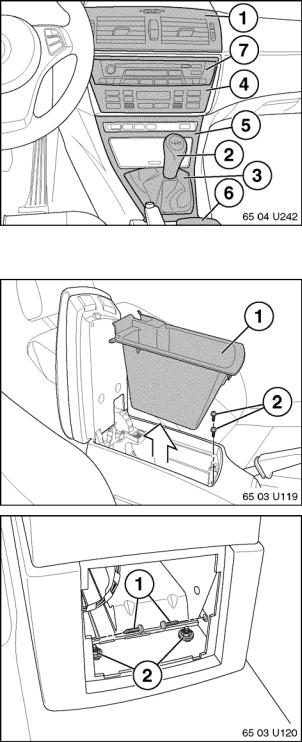
2. Remove the following components using procedures available through TIS:
• Center vent (1)
• Shifter knob (2)
• Shifter boot/Gear selector panel (3)
• Climate control panel (4)
• Console trim panel (5)
• Center cup holder (6)
• Parking brake handle/boot
• Rear ashtray assy. (not shown)
• Radio (7) – [ Required only for installation of optional Radio AUX Input adapter ]
3. Remove storage bin (1) and screws (2). Original storage bin will not be reused.
4. In rear of console remove 2 screws (1) and 2 nuts (2).
Installation Instruction P/N 01 29 0 403 646
4
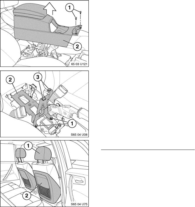
5.Remove 2 screws (1).
6.Lift rear of center console (2) and disconnect eject box electrical connections between center console and vehicle.
7.Center console may now be lifted out of position and removed from vehicle, taking care not to damage interior components.
8.Remove 2 forward nuts (1) securing base bracket (2) Remove base bracket from vehicle.
9.Remove 2 clips (3) from top of base bracket, as they will be reused in a later step. Base bracket will not be reused.
The following procedure must be performed for both front seats. Complete right side, then repeat procedure for left side.
10.Remove headrest (1).
11.Remove front seatbacks (2).
(Refer to RA 52 15 198)
Note: Seat back clips p/n 52 20 1 964 201 must be replaced with new parts.
(4 required)
12.Adjust seats to farthest rear position
Installation Instruction P/N 01 29 0 403 646

5
Headrest Installation
Note: Select Headrest monitor labeled “A” for left side and “B” for right side
1. Route monitor cable (2) down though headrest-post opening and insert headrests
(1). Position headrest at the highest lockable position (A).
Caution: Check for bent pins on monitor cable before attaching monitor cable to extension cable. If pins are damaged carefully adjust them back into position before connecting.
2. Align arrows on monitor and extension cables, then connect cables and secure with foam wrapping from kit.
Note: Passenger Seat Shown for Steps 3- 7.
3. Route extension cable 84 11 0 396 730 down thru seat back as shown.
Note: Secure extension cable to seat back bracket using cable ties (1) to prevent monitor cable connection from moving during headrest up/down adjustment.
Note: Routing of cable shown is for passenger seat only. Driver seat cable routing will differ.
4. Route extension cable through the lower edge of the backrest (1) and under the plastic clip at the edge of the seat (2).
5. Route remaining cable under seat towards the front of the vehicle as shown
Warning: Failure to perform these steps will result in damage to the monitor cable.
Installation Instruction P/N 01 29 0 403 646
6
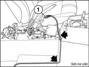
6.Route extension cable (1) from below seat (near air duct) up to center console area and tuck under carpeting. Allow approximately 12” of cable from back of front console to cable end.
7.Repeat steps 1 through 6 for left seat.
Note: Make sure there is enough slack in extension cables to allow full range of seat movement before proceeding.
Note: Seat removed for illustration purposes.
Installation Instruction P/N 01 29 0 403 646
7 Wiring Procedure for Vehicle Production 07/05 – On
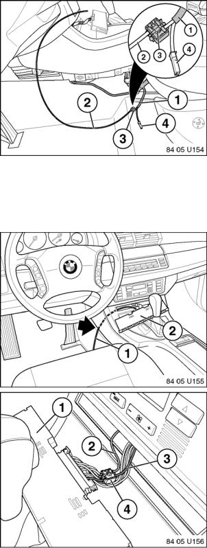
1. Cut off male pin from violet wire of DVD Wiring Harness (1) P/N 84 11 0 395 140.
2. Obtain approximately 3 feet of 18 - 20 gauge wire (2), not included in kit, to be used as extension wire.
3. Connect end of extension wire (2) to violet wire with pin removed in Step 22 from DVD wiring harness (1) using quick connector 61 13 8 364 566 (3)
Note: Black 2-pin connector (4) from DVD Wiring harness will not be utilized for this installation.
Note: Ensure that no exposed wires are present on the quick connect (3) as this may lead to a short circuit.
4. Remove switching center (2)
5. Route extension wire (1) through center console and up to opening for switching center (2).
6. Connect other end of extension wire (2) to violet/blue wire (3) located in pin location 23 of switching center (1) connector X1869 using quick connector 61 13 8 364 566 (4).
Note: Ensure that no exposed wires are present on the quick connect (4) as this may lead to a short circuit.
Installation Instruction P/N 01 29 0 403 646
 Loading...