


Table of Contents
Subject Page
N62B44 Engine . . . . . . . . . . . . . . . . . . . . . . . . . . . . . . . . . . . . . . . . . . . . .1
Objectives of the Module . . . . . . . . . . . . . . . . . . . . . . . . . . . . . . . . . . . . .1
Purpose of the System . . . . . . . . . . . . . . . . . . . . . . . . . . . . . . . . . . . . . . .2
Technical Data . . . . . . . . . . . . . . . . . . . . . . . . . . . . . . . . . . . . . . . . . . . . . .3
Engine Views . . . . . . . . . . . . . . . . . . . . . . . . . . . . . . . . . . . . . . . . . . . . . . .5
Components
Fresh Air System . . . . . . . . . . . . . . . . . . . . . . . . . . . . . . . . . . . . . . . . . . .6
- Air Routing . . . . . . . . . . . . . . . . . . . . . . . . . . . . . . . . . . . . . . . . . . . . . .6
- Throttle Valve . . . . . . . . . . . . . . . . . . . . . . . . . . . . . . . . . . . . . . . . . . . .7
- Intake Manifold . . . . . . . . . . . . . . . . . . . . . . . . . . . . . . . . . . . . . . . . . . .8
- Crankcase Venting System . . . . . . . . . . . . . . . . . . . . . . . . . . . . . . . . . .12
Exhaust System . . . . . . . . . . . . . . . . . . . . . . . . . . . . . . . . . . . . . . . . . . . 13
- Exhaust Manifold with Catalytic Converter . . . . . . . . . . . . . . . . . . . . . . .13
- Silencers . . . . . . . . . . . . . . . . . . . . . . . . . . . . . . . . . . . . . . . . . . . . . . .14
- Secondary Air System . . . . . . . . . . . . . . . . . . . . . . . . . . . . . . . . . . . . . 14
Ancillary Components . . . . . . . . . . . . . . . . . . . . . . . . . . . . . . . . . . . . . . . 16
- Belt Drive . . . . . . . . . . . . . . . . . . . . . . . . . . . . . . . . . . . . . . . . . . . . . .16
- Alternator . . . . . . . . . . . . . . . . . . . . . . . . . . . . . . . . . . . . . . . . . . . . . . 17
- Air Conditioning Compressor . . . . . . . . . . . . . . . . . . . . . . . . . . . . . . . . 19
- Starter Motor . . . . . . . . . . . . . . . . . . . . . . . . . . . . . . . . . . . . . . . . . . . .19
- Power Steering Pump . . . . . . . . . . . . . . . . . . . . . . . . . . . . . . . . . . . . . 19
Cylinder Heads . . . . . . . . . . . . . . . . . . . . . . . . . . . . . . . . . . . . . . . . . . . 20
- Engine Covers . . . . . . . . . . . . . . . . . . . . . . . . . . . . . . . . . . . . . . . . . . 21
- Valve Gear . . . . . . . . . . . . . . . . . . . . . . . . . . . . . . . . . . . . . . . . . . . . . 22
- Valvetronic . . . . . . . . . . . . . . . . . . . . . . . . . . . . . . . . . . . . . . . . . . . . . 23
- Bi-VANOS . . . . . . . . . . . . . . . . . . . . . . . . . . . . . . . . . . . . . . . . . . . . . 29
- Vacuum Pump . . . . . . . . . . . . . . . . . . . . . . . . . . . . . . . . . . . . . . . . . . 34
- Chain Drive . . . . . . . . . . . . . . . . . . . . . . . . . . . . . . . . . . . . . . . . . . . . 35

Subject Page
Components
Cooling System . . . . . . . . . . . . . . . . . . . . . . . . . . . . . . . . . . . . . . . . . . .38
- Coolant Circuit . . . . . . . . . . . . . . . . . . . . . . . . . . . . . . . . . . . . . . . . . . .38
- Water Pump . . . . . . . . . . . . . . . . . . . . . . . . . . . . . . . . . . . . . . . . . . . . 40
- Map-Controlled Thermostat. . . . . . . . . . . . . . . . . . . . . . . . . . . . . . . . . . 42
- Cooling Module . . . . . . . . . . . . . . . . . . . . . . . . . . . . . . . . . . . . . . . . . . .42
- Radiator . . . . . . . . . . . . . . . . . . . . . . . . . . . . . . . . . . . . . . . . . . . . . . . .43
- Expansion Tank . . . . . . . . . . . . . . . . . . . . . . . . . . . . . . . . . . . . . . . . . .43
- Transmission Oil/Water Heat Exchanger . . . . . . . . . . . . . . . . . . . . . . . . .44
- Electrically-Operated Fan . . . . . . . . . . . . . . . . . . . . . . . . . . . . . . . . . . . 44
- Viscous Coupling Fan . . . . . . . . . . . . . . . . . . . . . . . . . . . . . . . . . . . . . . 44
Engine block . . . . . . . . . . . . . . . . . . . . . . . . . . . . . . . . . . . . . . . . . . . . . 45
- Oil Sump . . . . . . . . . . . . . . . . . . . . . . . . . . . . . . . . . . . . . . . . . . . . . . . 45
- Crankcase . . . . . . . . . . . . . . . . . . . . . . . . . . . . . . . . . . . . . . . . . . . . . .45
- Crankshaft . . . . . . . . . . . . . . . . . . . . . . . . . . . . . . . . . . . . . . . . . . . . . .46
- Connecting Rods and Pistons . . . . . . . . . . . . . . . . . . . . . . . . . . . . . . . . 46
- Flywheel . . . . . . . . . . . . . . . . . . . . . . . . . . . . . . . . . . . . . . . . . . . . . . . .47
- Vibration Damper . . . . . . . . . . . . . . . . . . . . . . . . . . . . . . . . . . . . . . . . . 47
Lubrication System . . . . . . . . . . . . . . . . . . . . . . . . . . . . . . . . . . . . . . . . . 48
- Oil Jets . . . . . . . . . . . . . . . . . . . . . . . . . . . . . . . . . . . . . . . . . . . . . . . . . 48
- Oil Check Valve . . . . . . . . . . . . . . . . . . . . . . . . . . . . . . . . . . . . . . . . . . 48
- Oil Pump . . . . . . . . . . . . . . . . . . . . . . . . . . . . . . . . . . . . . . . . . . . . . . . 49
- Oil Filter . . . . . . . . . . . . . . . . . . . . . . . . . . . . . . . . . . . . . . . . . . . . . . . 51
- Pressure Control . . . . . . . . . . . . . . . . . . . . . . . . . . . . . . . . . . . . . . . . . 51
- Technical Data . . . . . . . . . . . . . . . . . . . . . . . . . . . . . . . . . . . . . . . . . . . 52
Review Questions . . . . . . . . . . . . . . . . . . . . . . . . . . . . . . . . . . . . . . . . . . . 53

1
N62 Engine
N62 ENGINE
Model: E65 - 745i / E66 - 745Li
Engine: N62B44
Production Date: 11/2001 - E65, 01/2002 - E66
Objectives of The Module
After Completing this module, you will be able to:
• Describe the two stage oil supply.
• Distinguish the difference between the left and right drive chain tensioning assemblies.
• Explain the Bi-VANOS operation.
• Understand the function of the Variable intake manifold.
• Explain the cooling circuit flow.
• List what chamber A and chamber B is used for in the Bi-VANOS system.
• Identify the Secondary air components.
• Explain how the initial VANOS position is retained when oil pressure is not present.
• List the proper drive belt removal procedure.
• Describe the throttle valve functions.
• Identify the N62B44 designation.
2
N62 Engine
N62 Engine
Purpose of The System
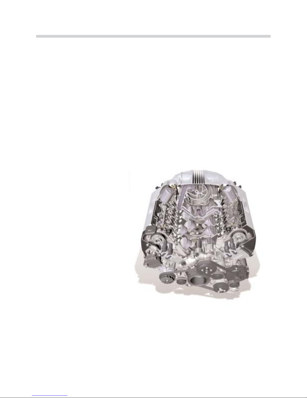
The N62B44 engine is a completely new development from the NG (New Generation) series
and is available as a B44 (4.4 liter).
The development objectives were:
• Reduction in fuel consumption
• Reduction in emissions
• Increased power
• Improved torque and torque curve
• Improved engine acoustics
The most important features of
the new N62 engine are:
• 8 cylinders in a 90º V configuration
• 2 four-valve cylinder heads
• Light-alloy design
• Newly-developed variable
intake manifold
• Valvetronic system
In conjunction with the Variable Intake Manifold, the Valvetronic system adapts the intake
valve lift to ensure optimum cylinder filling. The throttle valve use is limited during engine
operation to maintain a constant intake manifold vacuum.
TThhee NN6622 iiss tthhee bbeesstt eennggiinnee iinn iittss ccllaassss.. AAtt tthhiiss ttiimmee tthheerree iiss nnoo ootthheerr eennggiinnee oonn tthhee mmaarrkkeett
wwhhiicchh uusseess ccoommppaarraabbllee tteecchhnnoollooggyy..
To achieve these objectives, enhancements
were made in the following areas:
• Engine mechanicals
• Treatment of exhaust emissions
• Valve timing
• Engine management control
• Intake air flow
43-02-01

3
N62 Engine
Technical Data
EEnnggiinnee
NN6622BB4444
Design
8 Cylinder V
V Angle
90°
Displacement (cm3)
4,398
Bore/Stroke (mm)
92/82.7
Cylinder Gap (mm)
98
Main Crankshaft Bearing Diameter (mm)
70
Output (kW)
at speed (rpm)
325
6,100
Torque (Nm)
at Speed (RPM)
330
3,600
Cut-off speed (RPM)
6.500
Compression Ratio
10.0
Valves / Cylinders
4
Intake Valve Diameter (mm)
35
Exhaust Valve Diameter (mm)
29
Intake Valve Lift (mm)
0.3 – 9.85
Exhaust Valve Lift (mm)
9.7
Cams Open Period (º crankshaft)
282/254
Engine Weight (kg)
213
Fuel
91 Octane
Firing Order
1-5-4-8-6-3-7-2
Knock Sensor
Yes
Variable Intake Manifold
Yes
Digital Motor Electronics
ME 9.2 with Valvetronic Control Unit
Complies with Exhaust Emission Regulations
EU-3
EU-4
LEV
Engine Length (mm)
704
Fuel Consumption Saving Compared with the M62
14%

4
N62 Engine
42-02-02
5
N62 Engine
Engine Views
1
2
3
4
5
6
7
42-02-03
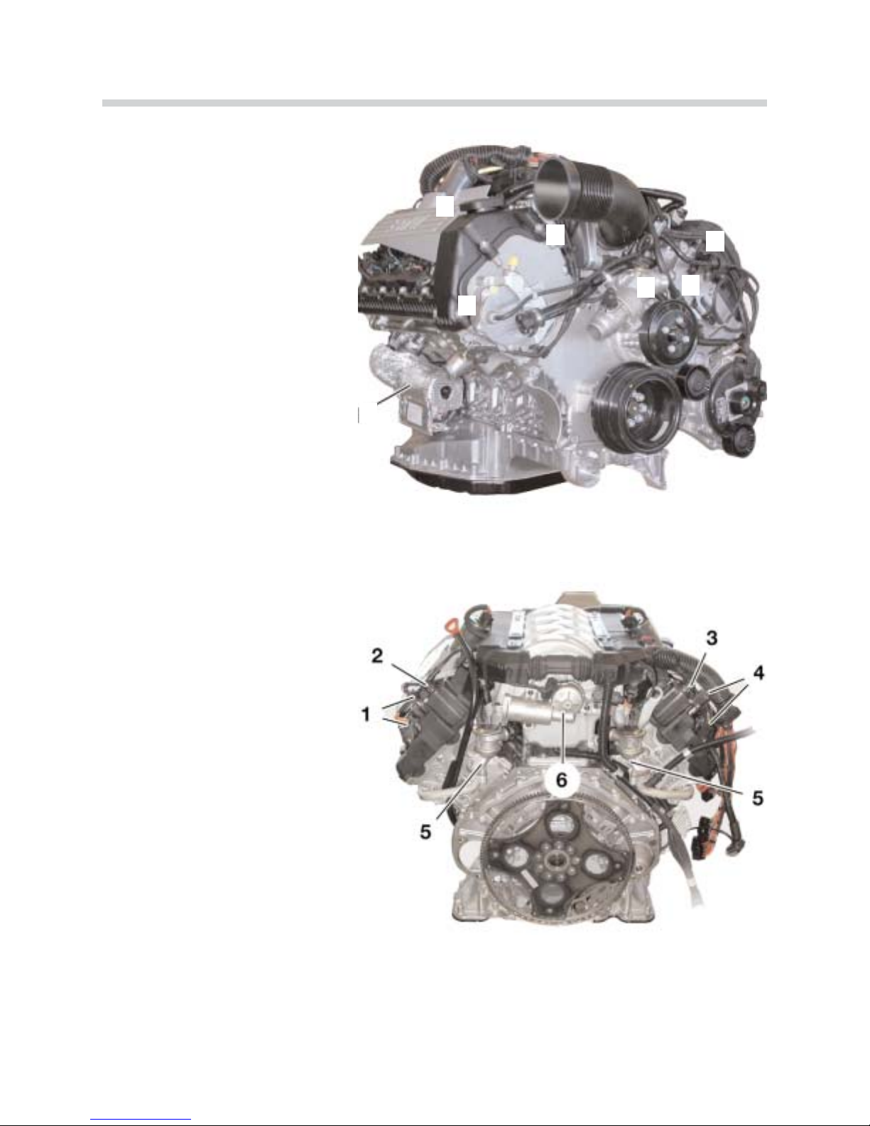
N62B44 Engine (Front View)
1. Starter Motor
2. Valvetronic Motor
3. Evaporative Emission Valve
4. VANOS Solenoid Valve
5. Thermostat Housing
6. Throttle Unit
7. Vacuum Pump
N62B44 Engine (Rear View)
1. Camshaft Position Sensor
Cylinder Bank 5-8
2. Valvetronic Eccentric Shaft
Position Sensor, Cylinder
Bank 5-8
3. Valvetronic Eccentric Shaft
Position Sensor, Cylinder
Bank 1-4
4. Camshaft Position Sensor
Cylinder Bank 1-4
5. Secondary Air Non-return Valves
6. Servomotor for Variable Intake
Manifold
42-02-04
Fresh Air System
Air Routing
The intake air passes through the air intake duct to the air cleaner, through the throttle section into the variable intake manifold and on to the two cylinder head intake ducts.
Increases in engine output and engine torque, as well as optimization of the engine torque
curve, are largely dependent on an optimum engine volumetric efficiency over the entire
engine speed range.
Long and short intake paths contribute to good volumetric efficiency in the lower and upper
speed ranges. Long air intake paths ensure optimum volumetric efficiency in the lower to
middle speed ranges. This optimizes the torque curve and increases the torque.
In order to optimize the power increase in the upper speed range, the engine requires short
air intake paths for better cylinder filling. The air intake system has been completely redevelopd in order to eliminate this inconsistency in terms of air intake path length.
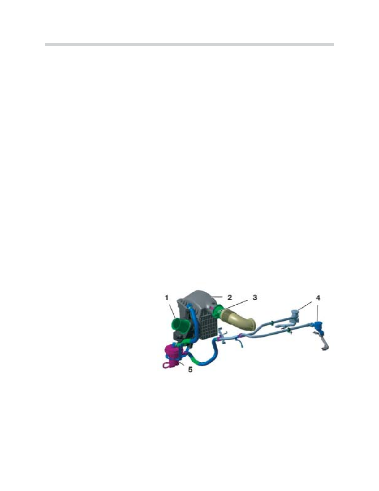
The air intake system consists of the following components:
6
N62 Engine
42-02-05
Air Intake System
1. Air Intake Duct
2. Air Cleaner Housing with Intake
Air Silencer
3. Intake Pipe with HFM (Hot-Film
Air-Mass Flow Sensor)
4. Secondary Air Valves
5. Secondary Air Pump

Throttle Valve
The throttle valve on the N62 is not necessary for engine load control. This is carried out
by the intake valves variable lift adjustment.
The tasks of the throttle valve are:
SSttaarrttiinngg tthhee eennggiinnee
Airflow is controlled by the throttle valve during the starting procedure when the air temperature is between 20 ºC and 60 ºC, .
If the engine is at operating temperature, it will be switched to non-throttle mode approximately 60 seconds after start up. In cold conditions however, the engine is started with
the throttle valve fully opened because this has a positive effect on the starting characteris-
tics.
EEnnssuurriinngg aa ccoonnssttaanntt vvaaccuuuumm ooff 5500 mmbbaarr iinn tthhee iinnttaakkee mmaanniiffoolldd
This vacuum is needed to exhaust the blow-by gases from the crankcase and the fuel
vapors from the activated charcoal filter.
TThhee bbaacckkuupp ffuunnccttiioonn
If the Valvetronic system should fail, the throttle valve implements conventional load control).
7
N62 Engine
42-02-25
Throttle Valve
• Throttle Valve Housing with Throttle Valve.
• Throttle Valve Actuator
• Two Throttle Valve Potentiometers
Intake Manifold
The N62 engine is equipped with a Variable Intake Manifold making it possible to reach a
generous torque curve even at low engine speeds, without incurring losses in engine output at higher speeds. It ensures that the engine exhibits optimum volumetric efficiency
through the entire range of speeds.
The new feature is the Variable Intake Manifold intake pipe length can be adjusted depending on the engine speed to provide efficient cylinder filling and scavenging. This is determined by the optimal matching of the intake pipe dimensions, the exhaust system and the
valve timing.
The intake manifold is located in the engine “V” and is mounted on the cylinder head intake
ports.
Function
In order to understand how engine speed relates to volumetric efficiency, the physical
processes within the intake pipe must be taken into consideration.
To ensure that there is good airflow to the engine cylinders, the intake pressure in front of
the intake valve should ideally be high. This means that good airflow (high gas molecule
density) in front of the intake valve is necessary.
8
N62 Engine
42-02-47
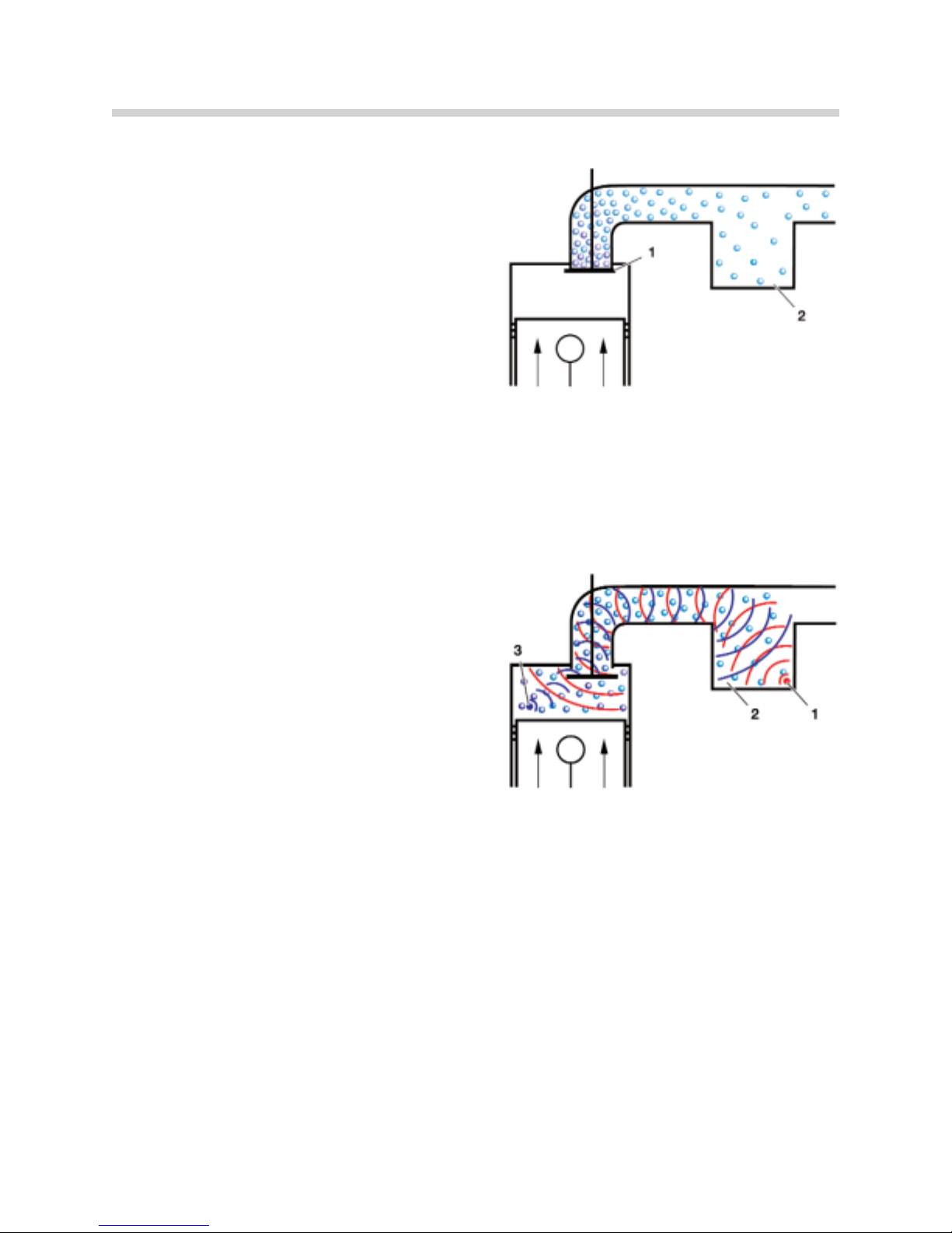
This is only possible if the intake valve is closed
and the mass inertia causes the intake air to
flow in front of the closed intake valve. The air is
compressed, the pressure and the air flow
increase.
IInnttaakkee aaiirr fflloowwss iinn ffrroonntt ooff tthhee cclloosseedd iinnttaakkee
vvaallvvee..
1. Closed intake valve
2. Intake manifold
As soon as the intake valve is opened, the pressurized intake air flows into the cylinder,
expands and draws the air molecules which follow into the cylinder. The suction waves form in
the intake pipe (moving at sonic speed) in the
opposite direction to the intake air.
These suction waves are reflected in the intake
manifold and create pressure waves which then
move once more at sonic speed in the direction
of the intake valve.
MMoovveemmeenntt ooff tthhee iinnttaakkee aaiirr wwiitthh tthhee iinnttaakkee vvaallvvee
ooppeenn..
1. Pressure waves
2. Air manifold
3. Suction waves
The intake pipe is at the optimum length when the pressure waves are at the intake valve
shortly before it is closed. The increase in pressure in front of the intake valve results in
increased air flow to the cylinders once more. This process is described as recharge effect.
The opening angle of the intake valve remains unchanged as the engine speed increases.
The opening time, however, is reduced proportionately (with conventional, non-Valvetronic
engines).
Since the suction waves and pressure waves expand at sonic speed, the suction path
length must be adapted depending on the engine speed to ensure that the tip of the pressure wave reaches the intake valve before it is closed.
9
N62 Engine
42-02-07
42-02-08

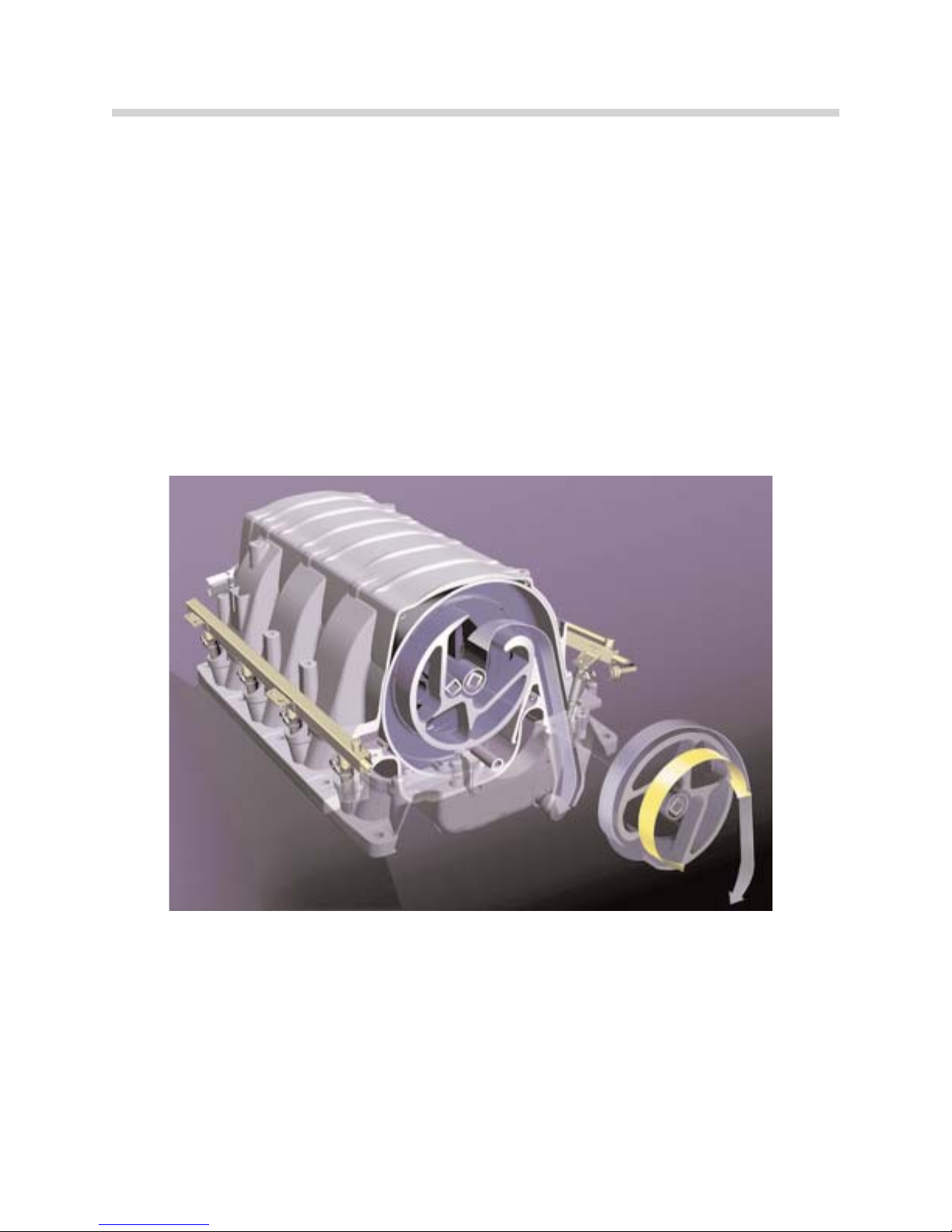
Each cylinder has its own intake pipe (1) which is connected to the manifold volume (6) via
a rotor (3). The rotors are supported by one shaft (4) per cylinder bank.
The second shaft, from which the rotor for the opposite cylinder bank is adjusted, is turned
by spur gears (5) in the opposite direction from the driven shaft.
The intake air flows via the manifold volume through the funnel (2) and on to the cylinders.
The intake path length is set as the rotor turns.
The intake path length can be adjusted according to the engine speed. Adjustment from
the long to short intake path begins at 3,500 rpm. If the engine speed increases, the intake
path length is progressively reduced, up to 6,200 rpm.
NNootteess::
10
N62 Engine
42-02-09
The Variable Intake Manifold
1. Intake Port
2. Funnel
3. Rotor
4. Shaft
5. Spur Gears
6. Manifold Volume
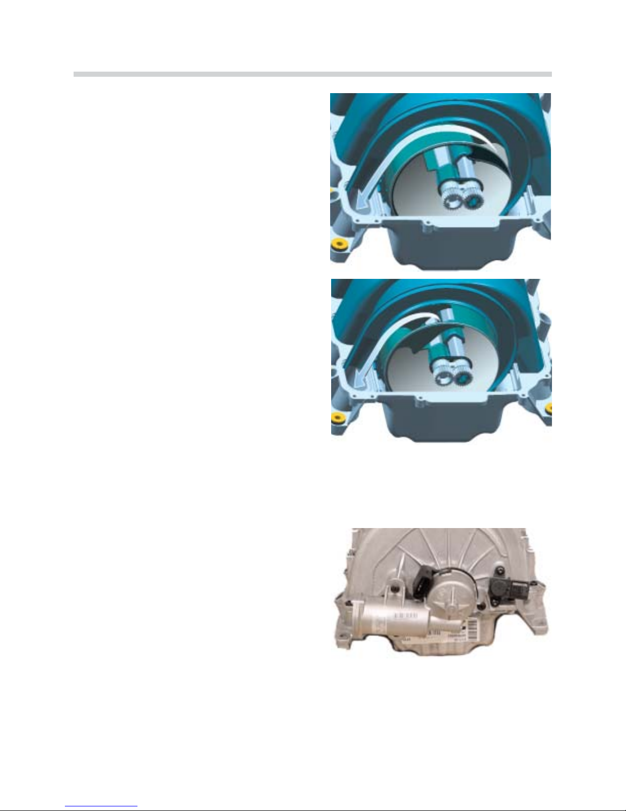
The intake path length is determined by the funnel position. If the engine speed is less than
3,500 rpm, the funnel is in the longer intake
path length position.
This means that the intake air must cover a
longer path to reach the cylinders.
•• IInnttaakkee mmaanniiffoolldd sseett ttoo lloonnggeerr iinnttaakkee ppaatthh..
When an engine speed of 6,200 rpm is
reached, the rotor is adjusted to the shorter
intake path position. The intake path to the
cylinders is now short.
The funnel can be progressively adjusted to any
point between the long/short intake path positions.
•• IInnttaakkee mmaanniiffoolldd sseett ttoo sshhoorrtt iinnttaakkee ppaatthh..
Funnel adjustment is carried out by the drive unit, which is located on the rear of the intake
manifold housing. The drive motor adjusts the drive shaft with funnels (cylinder bank 1-4).
The second shaft with funnels for cylinder bank 5-8 is synchronously adjusted by the spur
gears.
The drive motor is controlled by the ECM and
provides feedback about the funnel position via
an integral potentiometer.
11
N62 Engine
42-02-11
42-02-10
42-02-81

Crankcase Venting System
The crankcase vapors (a result of combustion blow-by gasses) are led out of the crankcase and back into the combustion chamber via the intake manifold. The blow-by gasses
contain droplets of oil which must be separated. The oil is returned to the sump while the
blow-by gasses are led into the intake pipe for combustion.
The engine performance is affected by the introduction of crankcase vapors into the combustion process, particularly in idle speed ranges. This influence is monitored by lambda
regulation.
The crankcase vapors are carried from the crankcase and into the cylinder head covers
through labyrinth separators (one per cylinder head). The oil which accumulates on the
walls of the labyrinth separators flows into the cylinder head via a siphon and from there
back to the sump.
The remaining vapors are passed to the engine for combustion via the pressure control
valve (5) in the intake manifold. One labyrinth separator with a pressure control valve is integrated in each of the two cylinder head covers.
The throttle valve is controlled so that there is always a 50 mbar vacuum in the intake manifold. The pressure control valve regulates the crankcase pressure to a low 0-30 mbar.
12
N62 Engine
43-02-12
Cylinder Head Cover
1-4. Opening for Spark Plugs
5. Pressure Control Valve
6. Opening Valvetronic Motor
7. Opening Valvetronic Sensor
Connector
8. Camshaft Sensor

Exhaust System
The exhaust system is completely redesigned for the N62B44 engine. It has been optimized in terms of cylinder filling, scavenging, sound level and rapid catalytic converter lightoff.
Exhaust Manifold with Catalytic Converter
Each cylinder bank is equipped with a four into two into one exhaust manifold. The manifold and the catalytic converter housing together form one component. A ceramic-bed precatalytic converter and a ceramic-bed main catalytic converter are arranged one behind the
other in the catalytic converter housing.
The mounting for the broadband planar oxygen sensors (Bosch LSU) and the secondary
oxygen sensors is located in front of and behind the catalytic converter.
13
N62 Engine
42-02-13
Exhaust System
1. Manifold with Integrated Catalytic Converter
2. Broadband Planar Oxygen Sensors
3. Secondary Oxygen Sensors
4. Exhaust Pipe with Front Silencer
5. Center Silencer
6. Exhaust Gas Flap
7. Rear Silencers
Silencers
• A 1.8 liter capacity front silencer has been fitted for each cylinder bank.
• A single 5.8 liter center silencer is fitted downstream of the two front silencers.
• The resonator type rear silencers have capacities of 12.6 and 16.6 liters.
Exhaust Gas Flap
The 12.6 liter rear silencer is fitted with an exhaust gas flap to keep noise to a minimum at
engine idle speed and low rpm. The exhaust gas flap is opened allowing additional flow
when:
• The a transmission gear is engaged
aanndd
• The engine speed is above 1,500 rpm
A vacuum-controlled diaphragm (actuator mounted on the silencer) opens and closes the
exhaust gas flap. The exhaust gas flap is closed with vacuum, and is sprung open by the
actuator (when vacuum is not present). The procedure is carried out using a solenoid valve
which is electrically controlled by the ECM.
Secondary Air System
Blowing additional air (secondary air) into the cylinder head exhaust ducts during the warmup phase results in a thermal secondary combustion which results in a reduction of the
non-combusted hydrocarbons (HC) and carbon monoxide (CO) in the exhaust gas. The
energy generated during this process heats up the catalytic converter faster during the
warm-up phase, and increases it’s conversion rate.
14
N62 Engine
43-02-05
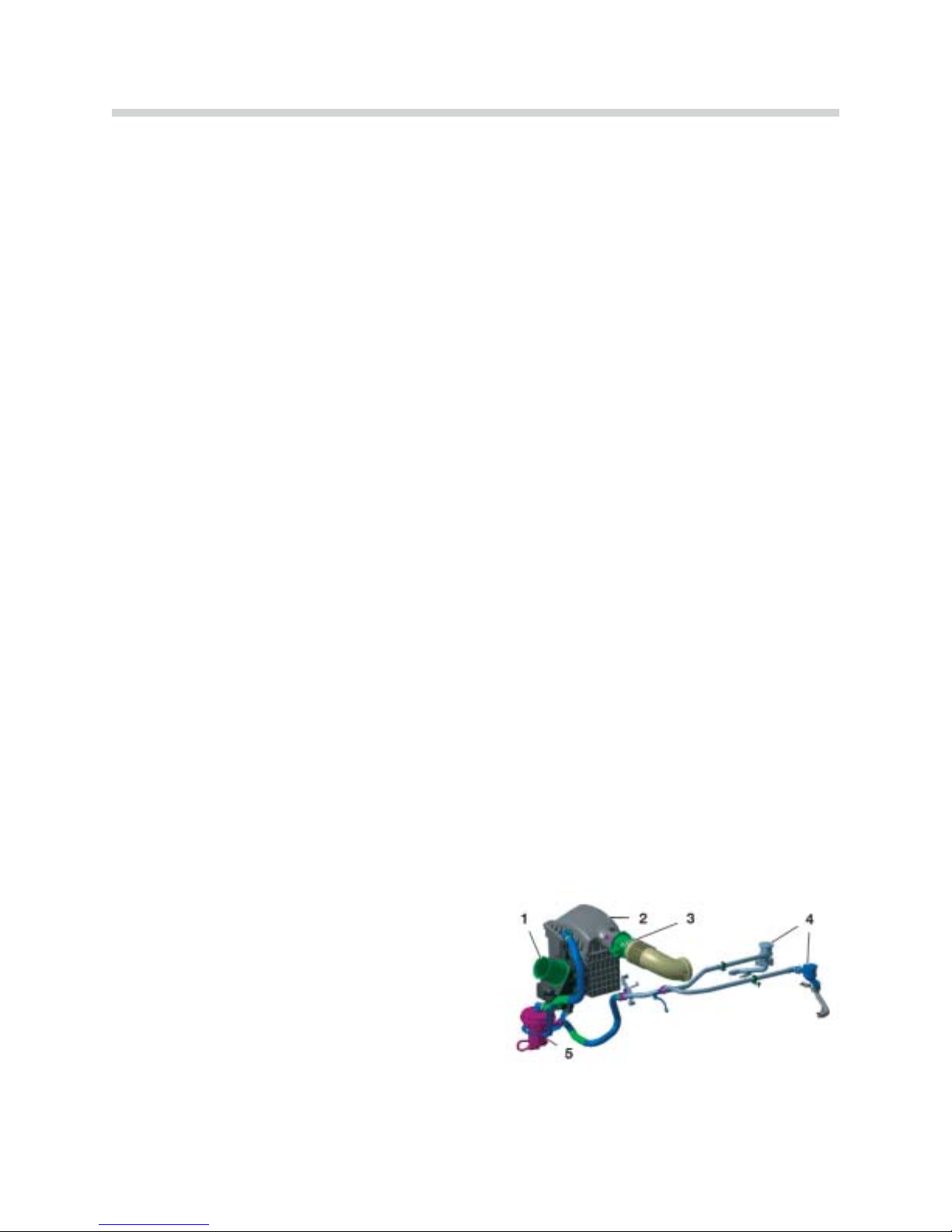
Secondary Air System
1. Air Intake Duct
2. Air Cleaner housing with Intake Air Silencer
3. Intake Pipe with HFM (Hot-Film Air-Mass
Sensor)
4. Non-return Valves
5. Secondary Air Pump

Secondary Air Pump (SLP)
The electrically-operated secondary air pump is mounted to the vehicle body. The pump
draws out filtered fresh air from the air cleaner housing during the warm-up phase and supplies it to the two secondary air Non-return Valves.
Once the engine has been started, the secondary air pump is supplied with voltage by the
ECM via the secondary air pump relay. It remains switched on until the engine has taken in
a certain amount of air.
The
OONN
period may be a maximum of 90 seconds and it depends on the following engine
operating conditions:
• Coolant temperature (from -10 ºC to approximately 60 ºC)
• Air temperature (NTC sensor in HFM)
• Engine speed
One non-return valve is mounted on each cylinder head (see also Engine Views).
The non-return valves are opened by the pressure generated from the secondary air pump.
The secondary air is led through a pipe to the secondary air ducts (integral in the cylinder
heads) for distribution into the exhaust ports.
The non-return valves are sprung closed when the secondary air pump is deactivated. This
prevents exhaust vapors, pressure and condensation from flowing back into the secondary
air pump.
15
N62 Engine
43-02-14
View From Rear of The Cylinder Head
1. Cylinder Head Lead
2. Non-return Valve (SLV)
3. Secondary Air Pump Connection
 Loading...