

BMW N62B36, N62B44 Service Training

New Generation N62 Engine
Course Contents/Background Material
Information status:
April 2001
BMW
Service Training

New Generation N62 Engine Chapter 1-7
Course contents/Background material
Contents
Page
CHAP 1 N62 engine 1
Introduction 1
- General information 1
Technical data 2
- Full load graphs 3
Views of the N62 engine 5
- N62B36 5
CHAP 2 N62 supplement to existing documents 1
- Crankcase venting system 1
- Alternator 1
- Characteristic mapping thermostat 1
- Engine management 1
- VANOS 1
- Valvetronic system 1
CHAP 3 N62 engine mechanics 1
Fresh air system 1
- Air routing 1
- Intake manifold 4
- Crankcase venting system 13
Exhaust system 15
- Structure 15
- Exhaust manifold with catalytic converter 16
- Silencer 16
- Secondary air system 17
Ancillary components and belt drive 20
- Belt drive 20
- Alternator 22
- Coolant compressor 26
- Starter motor 27
- Power steering pump 27
Cylinder heads 28
- Engine cover 29
- Cylinder head covers 30
- Valve gear 32
- Valvetronic 36
- Bi-VANOS (variable camshaft adjustment) 44
- Vacuum pump 49
- Chain drive 50
© BMW AG, Service Training

New Generation N62 Engine Chapter 1-7
Course contents/Background material
Cooling system 58
- Coolant circuit 58
- Water pump 63
- Map-controlled thermostat 67
- Cooling module 68
- Cooling radiator 69
- Coolant expansion tank 69
- Transmission oil/water heat exchanger (ÖWT) 70
- Electrically-operated fans 70
- Viscous coupling fan 70
Engine block 71
- Oil sump 71
- Crankcase 73
- Crankshaft 74
- Connecting rod and piston 76
- Flywheel 78
- Vibration damper 78
- Engine suspension 78
Lubrication system 79
- Oil circuit 79
- Oil check valve 80
- Oil pressure switch 81
- Oil pump 82
- Oil filter 83
- Pressure control 84
- Oil cooling 85
- Technical data 86
CHAP 4 N62 engine management system ME 9.2 1
Introduction 1
- General information 1
- ME 9.2 overview 2
- Components 9
Functional description 12
- General information 12
- Oxygen sensor regulation 13
- Oil condition sensor (OEZS) 14
- Variable intake manifold 17
- Idle speed control 17
Valvetronic 19
- General information 19
- Function 21
- Valvetronic control unit 23
- DME control unit 24
- DME main relay 24
- Valvetronic additional relay 24
- Valvetronic motors 24
- Valvetronic sensors 25
© BMW AG, Service Training

New Generation N62 Engine Chapter 1-7
Course contents/Background material
CHAP 5 N62 fuel system 1
- General information 1
- Injection valves 1
- Fuel pressure regulator 2
- Electric fuel pump (EKP) 2
- EKP regulation 2
CHAP 6 E65 fuel systems 1
- General information 1
- Filling the tank 3
- Tank ventilation 5
- Fuel supply system 8
Fuel tank leak diagnostic module 10
- General information 10
- Function 10
- Diagnostic procedure 11
CHAP 7 Glossary 1
© BMW AG, Service Training

New Generation N62 Engine Chapter 1 P.1
Course Contents/Background Material
N62 engine
Introduction
- General information
The N62 engine is a completely new development from the
NG (New Generation) series, and is available in two enginecapacity versions, B36=3.6 l and B44=4.4 l.
The development objectives were:
- A significant reduction in fuel consumption
- A reduction in the emission of pollutants
- Increased power
- Improved torque and torque curve
- Improved engine acoustics
In order to achieve these objectives, a complete package of
measures was introduced in the following areas:
- Engine mechanics
- Valve timing
- Intake air guidance
- Subsequent treatment of exhaust emissions
- Engine management control
The most important features of the new N62 engine are:
- 8 cylinders in 90º configuration
- 2 four-valve cylinder heads
- Light-alloy design
- Newly-developed variable intake manifold
- Valvetronic system
In conjunction with the newly-developed intake manifold, the
Valvetronic system, to which the intake valve lift can be adapted,
ensures optimum engine capacity.
Throttle valve use is conditional for engine load control.
The N62 is the best engine in its class. At this time there is no
other engine on the market which uses comparable technology.
© BMW AG, Service Training

New Generation N62 Engine Chapter 1 P.2
Course Contents/Background Material
Technical data
Engine N62B36 N62B44
Design 8 cylinder V 8 cylinder V
V angle 90º 90º
3
Displacement (cm
Bore/stroke (mm) 84/81.2 92/82.7
Cylinder gap (mm) 98 98
Main crankshaft bearing diameter (mm) 70 70
Crankshaft connecting rod bearing diameter (mm) 54 54
)
3,600 4,398
Output (kW)
at speed (rpm)
Torque (Nm)
at speed (rpm)
Cut-off speed (rpm) 6,500 6,500
Compression ratio 10.2 10.0
Valves/cylinders 4 4
Intake valve diameter (mm) 32 35
Exhaust valve diameter (mm) 29 29
Intake valve lift (mm) 0.3 - 9.85 0.3 - 9.85
Exhaust valve lift (mm) 9.7 9.7
Cams opening period (º crankshaft) 282/254 282/254
Engine weight (kg)
(construction group 11 to 13)
Fuel rating (RON) 98 98
Fuel (RON) 91-98 91-98
Firing sequence 1-5-4-8-6-3-7-2 1-5-4-8-6-3-7-2
Knock control Yes Yes
200
6,000
360
3,300
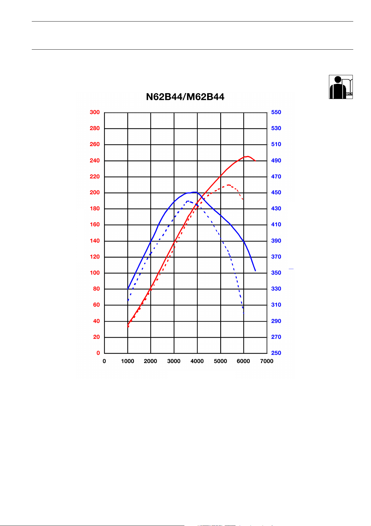
213 213
6,000
3,100
245
450
Variable intake manifold Yes Yes
Digital motor electronics ME9.2 +
Complies with exhaust emission regulations EU-3
Engine length (mm) 704 704
Fuel consumption saving compared with the M62 13% 14%
Vmax (km/h) E65 electronic cut-out 250 250
© BMW AG, Service Training
Valvetronic
control unit
EU-4
LEV
ME9.2 +
Valvetronic
control unit
EU-3
EU-4
LEV

New Generation N62 Engine Chapter 1 P.3
Course Contents/Background Material
- Full load graphs
N62B36
Output in kW
Speed
Fig. 1: Full load graphs comparison. Broken lines = M62B35
Torque in Nm
KT-8235
© BMW AG, Service Training
New Generation N62 Engine Chapter 1 P.4
Course Contents/Background Material
N62B44
Output in kW
Speed
Fig. 2: Full load graphs comparison. Broken lines = M62B44
Torque in Nm
KT-8236
© BMW AG, Service Training
New Generation N62 Engine Chapter 1 P.5
Course Contents/Background Material
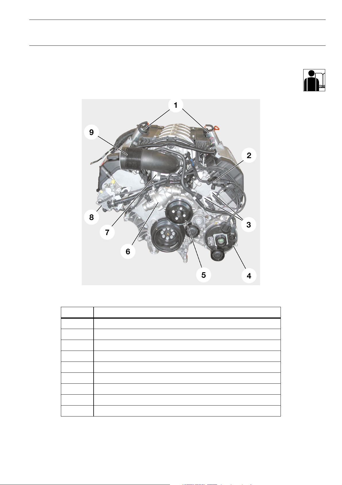
Views of the N62 engine
- N62B36
Fig. 3: N62 engine front view
Index Description
1 Valvetronic motors
2 Tank ventilation valve (AKF valve)
3 VANOS solenoid valve
4 Alternator
5 Pulley for the water pump
6 Thermostat housing
7 Throttle unit
8 Vacuum pump
9 Intake pipe to air cleaner
KT-7886
© BMW AG, Service Training
New Generation N62 Engine Chapter 1 P.6
Course Contents/Background Material
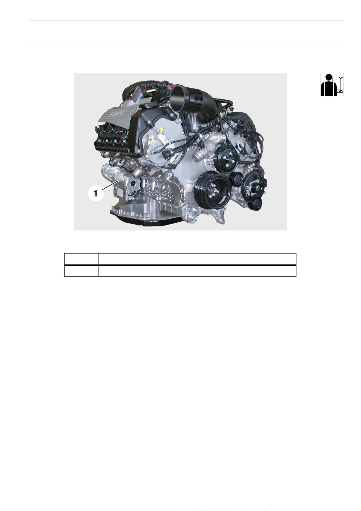
Fig. 4: N62 engine side view
Index Description
1 Starter motor with heat protection
KT-7682
© BMW AG, Service Training

New Generation N62 Engine Chapter 1 P.7
Course Contents/Background Material
Fig. 5: N62 engine rear view
Index Description
1 Camshaft position sensor, cylinder bank 5-8
2 Valvetronic eccentric shaft position sensor, cylinder bank 5-8
3 Valvetronic eccentric shaft position sensor, cylinder bank 1-4
4 Camshaft position sensor, cylinder bank 1-4
5 Secondary air valves
6 Servomotor for variable intake manifold
KT-7681
© BMW AG, Service Training

New Generation N62 Engine Chapter 2 P.1
Course Contents/Background Material
N62 supplement to existing documents
- Crankcase venting system
See the M44 for details of how the pressure control valve
functions
- Alternator
See the M57 EU for details of the principle
- Characteristic mapping thermostat
See the M62 and DME M5.2 for details of how the characteristic
mapping thermostats function
- Engine management
See N42 engine management
- VANOS
See the N42 engine
- Valvetronic system
See the N42 Valvetronic system
© BMW AG, Service Training
New Generation N62 Engine Chapter 3 P.1
Course Contents/Background Material
N62 engine mechanics
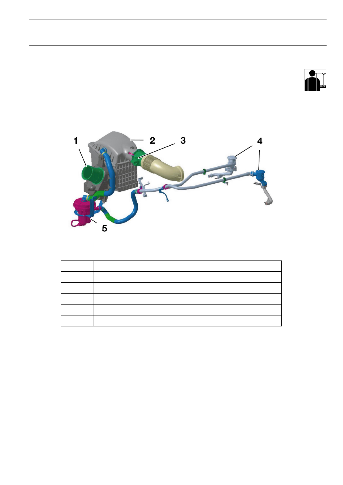
Fresh air system
- Air routing
KT-7888
Fig. 6: N62 air routing
Index Description
1 Air intake duct
2 Air cleaner housing with intake air silencer
3 Intake pipe with HFM (hot-film air-mass flow sensor)
4 Secondary air valves
5 Secondary air pump
The intake air passes through the air intake duct to the air
cleaner, through the throttle section into the variable intake
manifold, and on to the two cylinder head intake ducts.
In accordance with fording depth guidelines, the air intake ducts
are situated high in the engine compartment. Fording depth is as
follows:
- 150 mm water depth at 30 km/h
- 300 mm water depth at 14 km/h
- 450 mm water depth at 7 km/h
The air cleaner element is designed to be changed at
100,000 km intervals.
© BMW AG, Service Training

New Generation N62 Engine Chapter 3 P.2
Course Contents/Background Material
Increases in engine output and engine torque, as well as optimisation of the engine torque curve, are largely dependent on an
optimum engine volumetric efficiency over the entire engine
speed range.
Good volumetric efficiency in the lower and upper speed ranges
is achieved via long and short intake paths. Long air intake paths
ensure optimum volumetric efficiency in the lower to middle
speed ranges.
This optimizes the torque curve and increases the torque.
In order to optimize the power increase in the upper speed
range, the engine requires short air intake paths for better filling.
The air intake system has been completely reworked in order to
eliminate this inconsistency in terms of air intake path length.
The air intake system consists of the following components:
- Intake air ducts upstream of the air cleaner
- Air cleaner
- Intake pipe with HFM (hot-film air-mass flow sensor)
- Throttle unit
- Variable intake manifold
- Intake port
© BMW AG, Service Training

New Generation N62 Engine Chapter 3 P.3
Course Contents/Background Material
Throttle valve
The throttle valve mounted on the N62 is not necessary for
engine load control. This is carried out by the intake valves'
variable lift adjustment. The tasks of the throttle valve are:
- Starting the engine:
During the starting procedure and when the engine is idling at
a temperature of between 0 ºC and 60 ºC, airflow is controlled
by the throttle valve.
If the engine is at operating temperature, it will be switched to
non-throttle mode approximately 60 seconds after it is started
up. In cold conditions, however, the engine is started with the
throttle valve fully opened, since this has a positive effect on
the starting characteristics.
- Ensuring a constant vacuum pressure of 50 mbar in the intake
pipe:
This vacuum pressure is needed to exhaust the blow-by gases
from the crankcase and the fuel vapours from the activated
charcoal filter.
- The emergency running function:
If the Valvetronic system should fail, the throttle valve implements the engine's emergency running function (conventional
load control).
Throttle valve structure
- Throttle-valve housing with throttle valve
- Throttle valve actuator
- Two throttle valve potentiometers (feedback signal is contrarotating)
© BMW AG, Service Training

New Generation N62 Engine Chapter 3 P.4
Course Contents/Background Material
- Intake manifold
General information
The N62 engine is fitted with a variable intake manifold to make
it possible to reach a generous torque curve, even at low engine
speeds, without incurring losses in engine output at higher
speeds. It ensures that the engine exhibits optimum volumetric
efficiency through the entire range of speeds.
A new feature is that on the N62, the variable intake manifold
intake pipe length can be adjusted depending on the engine
speed.
The various requirements on a good petrol engine are
multilayered, and often appear to be contrary to one another.
The most important requirements are:
- High engine output
- High engine torque at favourable engine speeds
- Favourable torque curve
- Low pollutant emissions
- Smooth engine operation over the entire speed range
- Good engine acoustics
- Low fuel consumption
To achieve these objectives, every component of the engine, the
exhaust system and the engine management system must be
optimally matched to one another.
A particularly important factor is cylinder filling and scavenging.
This is determined by the optimal matching of the intake pipe
dimensions, the exhaust system and the valve timing.
Good cylinder filling is the basic prerequisite for the fulfilment of
the requirements.
The complete air intake system, and to a certain extent the
intake manifold, contribute to optimum cylinder filling.
© BMW AG, Service Training

New Generation N62 Engine Chapter 3 P.5
Course Contents/Background Material
The volumetric efficiency of the engine cylinders is determined
by physical processes which occur in the intake pipe while the
engine is running.
For optimum filling in every speed range, the engine needs an
intake manifold with different intake path lengths.
Long intake paths for low engine speeds, and short intake paths
for high engine speeds. Until now, the intake pipe length was
determined by the torque curve or output requirements.
Previously, if a good torque was needed at low engine speeds,
the engine was fitted with a long intake pipe. The consequence
was a poorly-running engine with insufficient end output.
If the emphasis is on a lively, high-capacity engine, a short intake
pipe is needed.
A fixed length intake pipe, therefore, is a compromise.
The introduction of the diversified intake manifold (DISA) has
made it possible to adjust the intake pipe to form a long or short
intake path, using a flap in the intake manifold.This variable
facilitates good torque curves as well as very good engine
output in the higher speed ranges.
With the N62, a variable intake manifold is used for the first time.
It ensures that the intake path is always the optimum length for
the engine speed, thus ensuring the best possible volumetric
efficiency.
© BMW AG, Service Training
New Generation N62 Engine Chapter 3 P.6
Course Contents/Background Material
Function
In order to understand how engine speed relates to volumetric
efficiency, the physical processes within the intake pipe must be
taken into consideration.
To ensure that there is good airflow to the engine cylinders, the
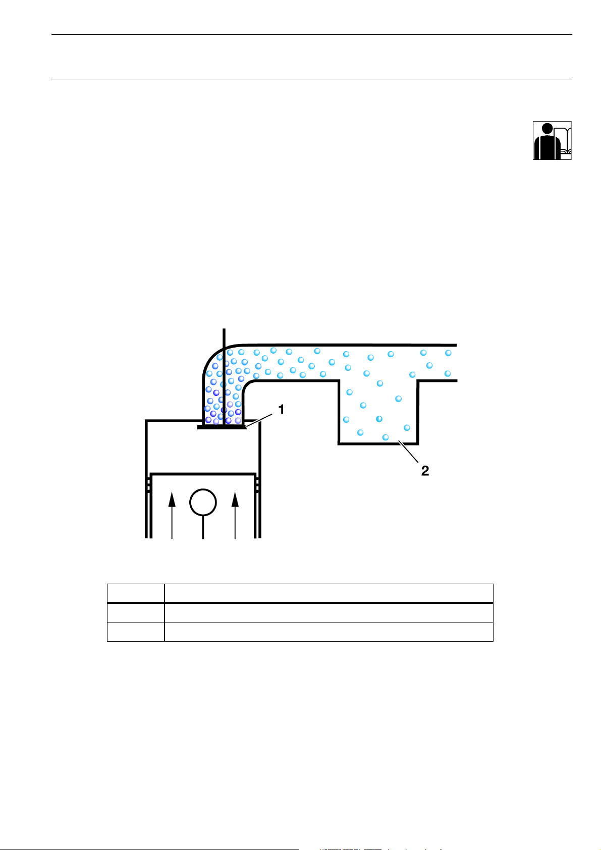
intake pressure in front of the intake valve should ideally be high.
This means that good airflow (high gas molecule density) in front
of the intake valve is necessary.
This is only possible if the intake valve is closed and the mass
inertia causes the intake air to flow in front of the closed intake
valve. The air is compressed and the pressure and the air flow
increase.
Fig. 7: Intake air flows in front of the closed intake valve
Index Description
1 Closed intake valve
2 Air manifold
© BMW AG, Service Training
KT-8409
New Generation N62 Engine Chapter 3 P.7
Course Contents/Background Material
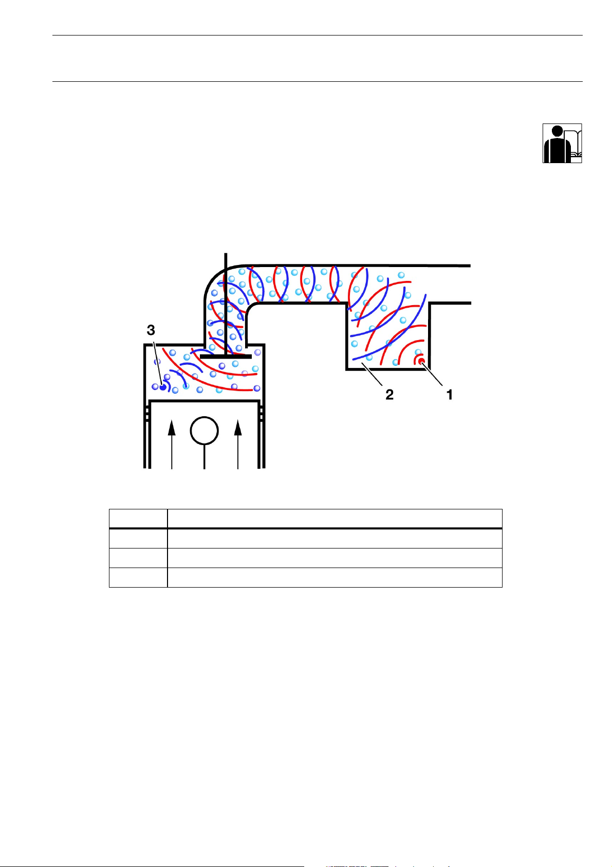
As soon as the intake valve is opened, the pressurized intake air
flows into the cylinder, expands, and draws the air molecules
which follow into the cylinder. This means that suction waves
form in the intake pipe, which move at sonic speed (333 m/s) in
the opposite direction to the intake air. These suction waves are
reflected in the intake manifold and create pressure waves
which then move once more at sonic speed in the direction of
the intake valve.
Fig. 8: Movement of the intake air with the intake valve open
Index Description
1 Pressure waves
2 Air manifold
3 Suction waves
KT-8408
© BMW AG, Service Training

New Generation N62 Engine Chapter 3 P.8
Course Contents/Background Material
The intake pipe is at the optimum length when the pressure
waves are at the intake valve shortly before it is closed. The
increase in pressure in front of the intake valve results in
increased air flow to the cylinders once more.
This process is described as recharge effect. The opening angle
of the intake valve remains unchanged as the engine speed
increases. The opening time, however, is reduced proportionately (with conventional, non-Valvetronic engines).
Since the suction waves and pressure waves expand at sonic
speed, the suction path length must be adapted depending on
the engine speed to ensure that the tip of the pressure wave
reaches the intake valve before it is closed.
© BMW AG, Service Training

New Generation N62 Engine Chapter 3 P.9
Course Contents/Background Material
KT-6799
Fig. 9: Variable intake manifold housing
Index Description
1 Drive unit
2 Thread for engine cover
3 Crankcase venting system connection
4 Tank ventilation connection
5 Intake air
6 Injection valve holes
7 Fuel rail thread
The intake manifold is located in the V of the engine, and is
mounted on the cylinder head intake ducts.
The variable intake manifold housing is made from a magnesium
alloy.
© BMW AG, Service Training

New Generation N62 Engine Chapter 3 P.10
Course Contents/Background Material
KT-6800
Fig. 10: Interior view of the variable intake manifold
Index Description
1 Intake port
2 Funnel
3 Rotor
4 Shaft
5 Spur gears
6 Manifold volume
Each cylinder has its own intake pipe (1) which is connected to
the manifold volume (6) via a rotor (3).
The rotors are supported by one shaft (4) per cylinder bank.
The second shaft, from which the rotor for the opposite cylinder
bank is adjusted, is turned by spur gears (5) in the opposite
direction from the driven shaft.
The intake air flows via the manifold volume through the
funnel (2) and on to the cylinders.
The intake path length is set as the rotor turns.
© BMW AG, Service Training

New Generation N62 Engine Chapter 3 P.11
Course Contents/Background Material
Setting the intake manifold
Fig. 11: Intake manifold set to short intake path
KT-8114
Fig. 12: Intake manifold set to longer intake path
© BMW AG, Service Training
KT-8115

New Generation N62 Engine Chapter 3 P.12
Course Contents/Background Material
The intake path length can be adjusted according to the engine
speed. Adjustment from long to short intake path begins at
3,500 rpm. If the engine speed increases, the intake path length
is linearly reduced, up to 6,200 rpm.
The intake path length is determined by the funnel position.
If the engine speed is less than 3,500 rpm, the funnel is in the
longer intake path length position (see illustration on previous
page). This means that the intake air must cover a longer path to
reach the cylinders.
When an engine speed of 6,200 rpm is reached, the rotor is
adjusted to the shorter intake path position. The intake path to
the cylinders is now short.
The funnel can be linearly adjusted to any point between the
long/short intake path positions.
Funnel adjustment is carried out by the drive unit, which is
located on the rear of the intake manifold housing.
The drive motor then also adjusts the drive shaft with funnels
(cylinder bank 1-4). The second shaft with funnels for cylinder
bank 5-8 is synchronously adjusted by the spur gears.
The drive motor is controlled by the DME and is intended for
providing feedback about the funnel position via a potentiometer.
© BMW AG, Service Training

New Generation N62 Engine Chapter 3 P.13
Course Contents/Background Material
- Crankcase venting system
General information
The gases which penetrate the crankcase as a result of combustion (blow-by gases) must not escape outside into the
atmosphere. This is why they are led out of the crankcase and
back into the combustion chamber via the intake manifold.
The blow-by gases contain droplets of oil. If these blow-by
gases carrying droplets of oil were to be fed into the engine
combustion zone, there would be the following consequences:
- Higher oil consumption
- An effect on pollutant emissions
- Blue smoke
In order to avoid this, the blow-by gases must be separated from
the engine oil. The oil is returned to the sump once separated.
The blow-by gases are led into the intake pipe for combustion.
Engine running is affected if the blow-by gases are returned to
the combustion process, particularly in near-idling speed
ranges.
This influence is taken into account by lambda regulation.
The blow-by gases must be intentionally passed into the intake
tract to avoid negative side-effects
© BMW AG, Service Training
New Generation N62 Engine Chapter 3 P.14
Course Contents/Background Material
KT-7711
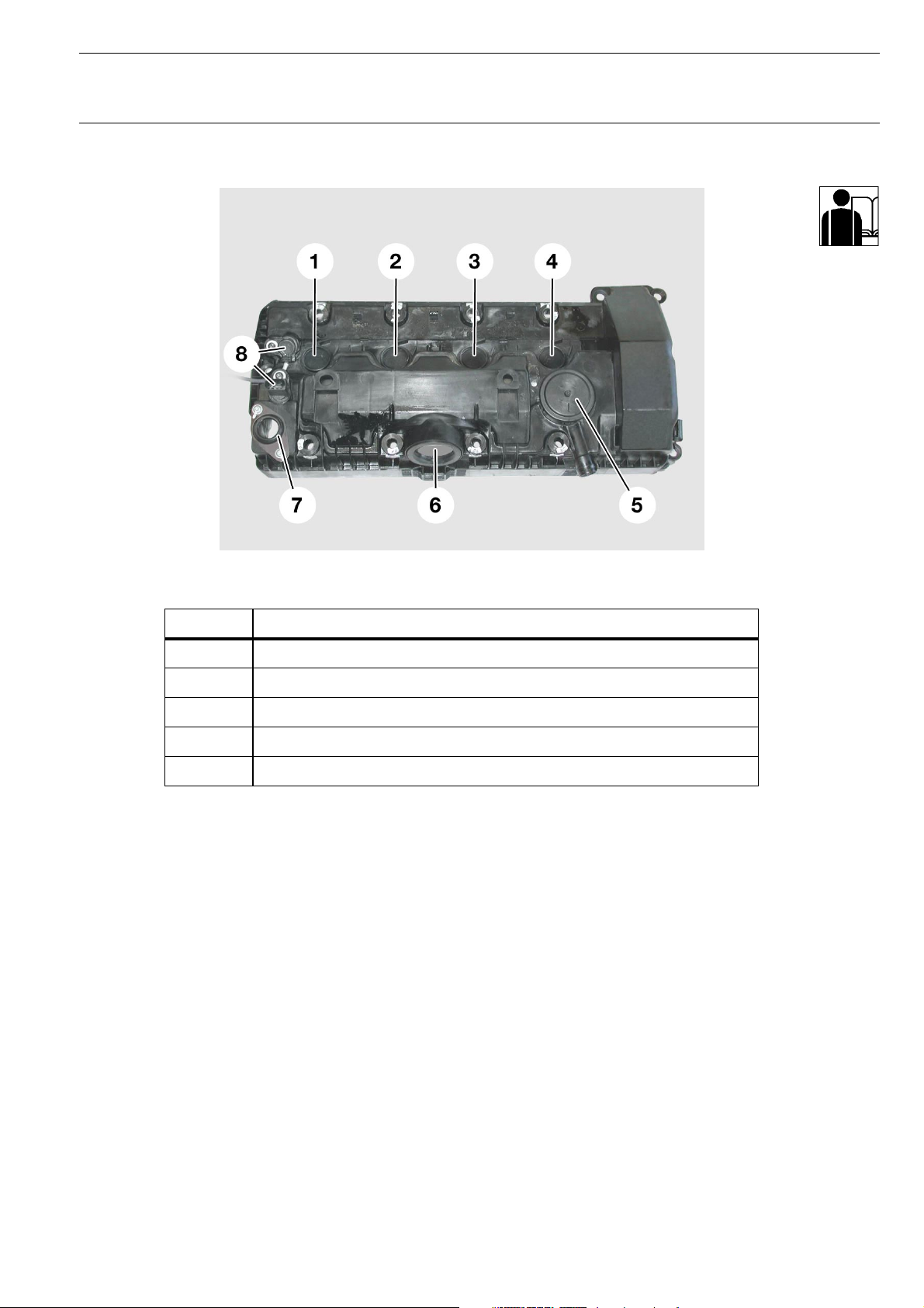
Fig. 13: Cylinder head cover with labyrinth separator
Index Description
1-4 Openings for spark plugs
5 Pressure control valve
6 Opening for Valvetronic motor
7 Opening for Valvetronic sensor connector
8 Camshaft sensor
The crankcase vapours (blow-by gases) produced during
combustion are carried from the crankcase and into the cylinder
head cover via a labyrinth separator.
The oil which accumulates on the walls of the labyrinth
separator flows into the cylinder head via a siphon, and from
there flows back to the sump. The remaining gases are passed
back to the engine for combustion via the pressure control
valve (5) in the intake manifold.
One labyrinth separator with pressure control valve is integrated
in each of the two cylinder head covers.
The throttle valve is controlled such that there is always a
vacuum pressure of 50 mbar in the intake manifold.
The pressure control valve regulates the crankcase pressure to a
low 0-30 mbar.
© BMW AG, Service Training
New Generation N62 Engine Chapter 3 P.15
Course Contents/Background Material
Exhaust system
- Structure
KT-7066
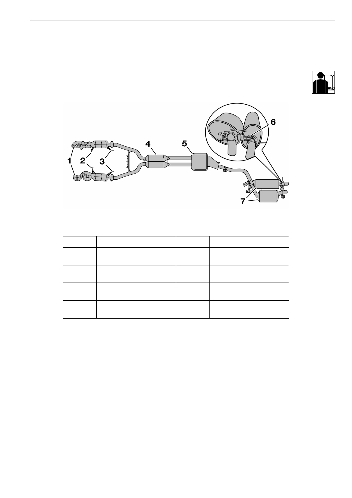
Fig. 14: Exhaust system
Index Description Index Description
1 Manifolds with integrated
catalytic converter
2 Broadband planar oxygen
sensors
3 Secondary oxygen sensor
(steep characteristic curve)
4 Exhaust pipe with front
silencer
5 Centre silencer
6 Exhaust gas flap
7 Rear silencers
The exhaust system was completely redesigned for the N62B36
and N62B44 engines, and is identical in each engine. It has
been optimized in terms of cylinder filling and scavenging, the
acoustic system and rapid catalytic converter light-off.
© BMW AG, Service Training

New Generation N62 Engine Chapter 3 P.16
Course Contents/Background Material
- Exhaust manifold with catalytic converter
A four-into-two-into-one manifold has been fitted for each
cylinder bank. The manifold and the catalytic converter housing
together form one component.
A ceramic-bed pre-catalytic converter and a ceramic-bed main
catalytic converter are arranged one behind the other in the
catalytic converter housing.
The supports for the broadband planar oxygen sensors
(Bosch LSU 4.2) and the secondary oxygen sensors are located
in front of and behind the catalytic converter in the headpipe or
catalytic converter outlet funnel.
- Silencer
An absorption-type, 1.8 l capacity front silencer has been fitted
for each cylinder bank.
An absorption-type, 5.8 l centre silencer is fitted downstream of
the two front silencers.
The rear silencers are of the resonator type, and have capacities
of 12.6 and 16.6 litres.
Exhaust gas flap
To keep noise to a minimum at engine idling speed and near
engine idling speeds, the rear silencer is fitted with an exhaust
gas flap. The exhaust gas flap is opened when a gear is
engaged and the engine speed is above 1,500 rpm. This
activates an additional rear silencer capacity of 14 litres.
A vacuum-controlled diaphragm box opens and closes the
exhaust gas flap. The exhaust gas flap is closed using vacuum
pressure, and is opened by ventilating the diaphragm box.
This control procedure is carried out using a solenoid valve
which is electrically actuated from the DME.
© BMW AG, Service Training

New Generation N62 Engine Chapter 3 P.17
Course Contents/Background Material
- Secondary air system
General information
KT-7888
Fig. 15: N62 air routing
Index Description
1 Air intake duct
2 Air cleaner housing with intake air silencer
3 Intake pipe with HFM (hot-film air-mass flow sensor)
4 Secondary air valves
5 Secondary air pump
Blowing additional air (secondary air) into the cylinder head
exhaust duct during the warm-up phase results in a thermal
secondary combustion which in turns results in a reduction of
the non-combusted hydrocarbons (HC) and carbon monoxide
(CO) contained in the exhaust vapours.
The energy generated during this process heats up the catalytic
converter faster during the warm-up phase, and increases its
conversion rate.
© BMW AG, Service Training
New Generation N62 Engine Chapter 3 P.18
Course Contents/Background Material
Secondary air pump (SLP)
The electrically-operated secondary air pump is fixed to the
engine compartment body. The pump draws out filtered fresh air
from the air cleaner housing during the warm-up phase and
supplies it to the two secondary air valves.
Once the engine has been started, the SLP is supplied with onboard voltage by the DME via the secondary air pump relay. It
remains switched on until the engine has taken in a certain
amount of air.
The ON period may be a maximum of 90 seconds, and depends
on the following engine operating conditions:
- Coolant temperature (from -10 ºC to approximately 60 ºC)
- Air flow
- Engine speed
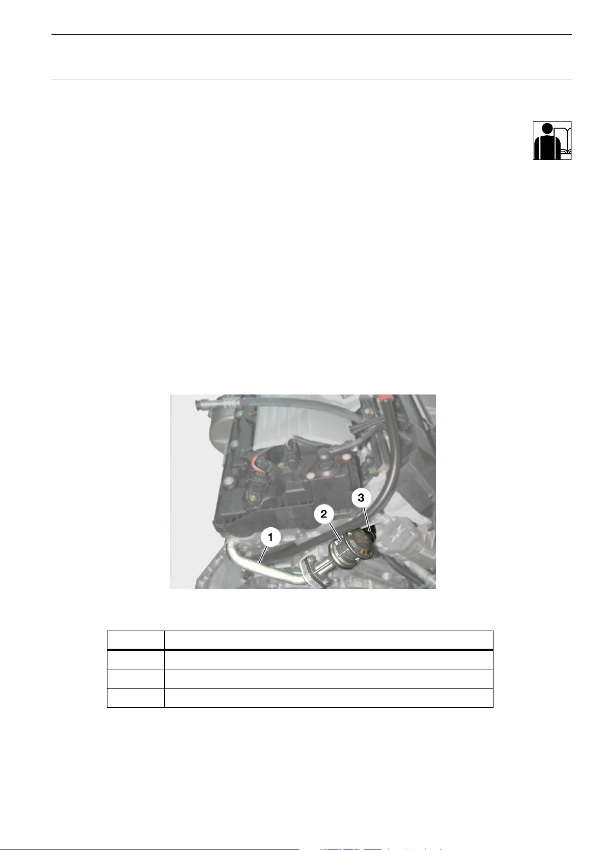
Secondary air valves (SLV)
Fig. 16: Secondary air valve
Index Description
1 Cylinder head lead
KT-8090
2 Secondary air valve
3 Secondary air pump connection
© BMW AG, Service Training
 Loading...