


Technical�training.
Product�information.
N57TU�Engine
BMW�Service

General�information
Symbols�used
The�following�symbol�is�used�in�this�document�to�facilitate�better�comprehension�or�to�draw�attention
to�very�important�information:
Contains�important�safety�information�and�information�that�needs�to�be�observed�strictly�in�order�to
guarantee�the�smooth�operation�of�the�system.
Information�status�and�national-market�versions
BMW�Group�vehicles�meet�the�requirements�of�the�highest�safety�and�quality�standards.�Changes
in�requirements�for�environmental�protection,�customer�benefits�and�design�render�necessary
continuous�development�of�systems�and�components.�Consequently,�there�may�be�discrepancies
between�the�contents�of�this�document�and�the�vehicles�available�in�the�training�course.
This�document�basically�relates�to�the�European�version�of�left�hand�drive�vehicles.�Some�operating
elements�or�components�are�arranged�differently�in�right-hand�drive�vehicles�than�shown�in�the
graphics�in�this�document.�Further�differences�may�arise�as�the�result�of�the�equipment�specification�in
specific�markets�or�countries.
Additional�sources�of�information
Further�information�on�the�individual�topics�can�be�found�in�the�following:
• Owner's�Handbook
• Integrated�Service�Technical�Application.
Contact:�conceptinfo@bmw.de
©2010�BMW�AG,�Munich
Reprints�of�this�publication�or�its�parts�require�the�written�approval�of�BMW�AG,�München
The�information�contained�in�this�document�forms�an�integral�part�of�the�technical�training�of�the
BMW�Group�and�is�intended�for�the�trainer�and�participants�in�the�seminar.�Refer�to�the�latest�relevant
information�systems�of�the�BMW�Group�for�any�changes/additions�to�the�technical�data.
Contact
Gernot�Nehmeyer/Udo�Metz
Telephone�+49�(0)�89�382�34059/+49�(0)�89�382�58506
gernot.nehmeyer@bmw.de/udo.metz@bmw.de
Status�of�the�information:�November�2010
BV-72/Technical�Training

N57TU�Engine
Contents
1. Introduction.............................................................................................................................................................................................................................................1
1.1. Technical�data............................................................................................................................................................................................................. 2
1.2. Engine�identification......................................................................................................................................................................................... 3
1.2.1. Engine�designation............................................................................................................................................................3
1.2.2. Engine�identification........................................................................................................................................................5
1.3. Design�features.........................................................................................................................................................................................................6
2. Engine�Mechanical.....................................................................................................................................................................................................................7
2.1. Crankcase...........................................................................................................................................................................................................................7
2.2. Oil�sump............................................................................................................................................................................................................................... 9
2.3. Crankshaft..................................................................................................................................................................................................................... 11
2.4. Piston.................................................................................................................................................................................................................................... 13
2.5. Connecting�rod..................................................................................................................................................................................................... 13
2.6. Cylinder�head...........................................................................................................................................................................................................14
2.7. Cylinder�head�gasket...................................................................................................................................................................................16
2.8. Crankcase�ventilation.................................................................................................................................................................................. 17
2.9. Camshaft�drive�system.............................................................................................................................................................................20
2.10. Camshafts�and�timing................................................................................................................................................................................21
2.10.1. Timing................................................................................................................................................................................................ 23
3. Belt�Drive.................................................................................................................................................................................................................................................24
3.1. N57�engine.................................................................................................................................................................................................................. 24
3.2. N57TU�engine........................................................................................................................................................................................................ 25
4. Oil�Supply...............................................................................................................................................................................................................................................27
4.1. Oil�circuit......................................................................................................................................................................................................................... 27
4.2. Oil�pump.......................................................................................................................................................................................................................... 28
4.2.1. Pressure�limiting�valve............................................................................................................................................. 30
4.3. Oil�filter�module....................................................................................................................................................................................................34
4.3.1. Transmission�oil�cooling....................................................................................................................................... 36
5. Intake�Air,�Exhaust�and�Emission�Sys............................................................................................................................................. 40
5.1. Intake�air�system.................................................................................................................................................................................................42
5.1.1. Intake�manifold.....................................................................................................................................................................44
5.2. Vacuum�system.................................................................................................................................................................................................... 46
5.2.1. Vacuum�pump....................................................................................................................................................................... 47
5.2.2. Electro-pneumatic�changeover�valve�(EUV).......................................................................... 48
5.3. Exhaust�emission�system.....................................................................................................................................................................49
5.3.1. Exhaust�turbocharger�(VNT)...........................................................................................................................50
5.3.2. Exhaust-gas�recirculation....................................................................................................................................55
5.3.3. EGR�valve/actuator.........................................................................................................................................................56

N57TU�Engine
Contents
5.3.4. Exhaust�after-treatment.........................................................................................................................................58
6. Fuel�Preparation.........................................................................................................................................................................................................................60
6.1. High�pressure�pump..................................................................................................................................................................................... 61
6.1.1. Fuel�quantity�control�valve................................................................................................................................66
6.1.2. Volumetric�flow�regulation�functional�description........................................................ 68
6.1.3. Rail�pressure�sensor................................................................................................................................................... 69
6.2. Leakage�oil�line.....................................................................................................................................................................................................69
6.3. Injector................................................................................................................................................................................................................................ 70
6.3.1. Injector�CRI2.5......................................................................................................................................................................71
6.3.2. Injection�volume�calibration.............................................................................................................................74
7. Engine�Electrical�System..........................................................................................................................................................................................76
7.1. Preheating�control�unit............................................................................................................................................................................. 80
7.1.1. Glow�plug......................................................................................................................................................................................81
7.2. Sensors�and�actuators..............................................................................................................................................................................82
7.2.1. Crankshaft�sensor........................................................................................................................................................... 82
7.2.2. Camshaft�sensor...............................................................................................................................................................85
7.2.3. Hot-film�air�mass�meter.........................................................................................................................................85
7.2.4. Rail�pressure�sensor................................................................................................................................................... 86
7.2.5. Boost-pressure�sensor�......................................................................................................................................... 87
7.2.6. Charge-air�temperature�sensor............................................................................................................... 88
7.2.7. Coolant�temperature�sensor.......................................................................................................................... 88
7.2.8. Oxygen�sensor..................................................................................................................................................................... 89
7.2.9. NOx�sensors............................................................................................................................................................................ 90
7.2.10. Particulate�matter�sensor.................................................................................................................................... 90
7.2.11. Exhaust�gas�temperature�sensor............................................................................................................ 92
7.2.12. Fuel�temperature�and�pressure�sensor.......................................................................................92
7.2.13. Exhaust�back-pressure�sensor�upstream�of�exhaust
turbocharger.............................................................................................................................................................................93
7.2.14. Throttle�valve�actuator.............................................................................................................................................94
8. Engine�Control�Functions........................................................................................................................................................................................ 96
8.1. Air�supply....................................................................................................................................................................................................................... 96
8.1.1. Boost-pressure�control...........................................................................................................................................96
8.2. Fuel�supply.................................................................................................................................................................................................................. 97
8.2.1. Fuel�injection...........................................................................................................................................................................97
8.2.2. High-pressure�control............................................................................................................................................... 97
8.2.3. Injector�volume�calibration................................................................................................................................ 97
8.2.4. Volume�calibration�control................................................................................................................................. 98
8.2.5. Zero�volume�calibration..........................................................................................................................................98

N57TU�Engine
Contents
8.2.6. Mean�volume�adaptation..................................................................................................................................... 98
8.3. Exhaust�emission�system.....................................................................................................................................................................99
8.3.1. Oxygen�control.....................................................................................................................................................................99
8.3.2. Lambda�adaptation....................................................................................................................................................... 99
8.3.3. Exhaust�gas�recirculation�(EGR)...........................................................................................................100


N57TU�Engine
1.�Introduction
The�N57TU�engine�is�based�on�the�N57�engine�which�was�not�available�in�the�US�but�has�been
used�in�other�markets�for�some�time.�The�differences�between�the�N57TU�engine�and�N57�engine�are
essentially�the�same�as�the�differences�between�the�N47TU�engine�and�N47�engine.�This�document
deals�exclusively�with�the�adaptations/changes�made�with�regard�to�the�N57TU�engine.�The�N57TU
6�cylinder�engine�replaces�the�(M57D30T2)�6�cylinder�which�was�first�introduced�to�the�US�market�in
2009�with�the�E90�335d�and�the�E70�xDrive35d.
The�N57TU�engine�was�installed�in�the�F10�535d�and�535d�xDrive�2014�models�from�7/2013
start�production�and�was�also�installed�on�the�new�2014�X5�model�xDrive35d�(F15)�introduced�in
September�of�2013.
Model Series Engine Start�of�production
535d F10 N57D30O1 7/13
535d�xDrive F10 N57D30O1 7/13
X5�xDrive35d F15 N57D30O1 9/13
The�N47TU�and�the�N57TU�engine�are�considered�second�generation�BMW�diesel�engines
(in�the�US�market).�The�exhaust�after-treatment�systems�and�components�of�the�N47TU�and
the�N57TU�have�been�especially�design�to�comply�with�current�(ULEV�II)�US�market�emission
regulations�and�thus�differ�from�those�used�with�the�previous�US�diesel�(M57D30T2)�engine.
1

N57TU�Engine
1.�Introduction
1.1.�Technical�data
The�N57TU�engine�technical�data�is�described�in�the�following�table.
Full-load�diagram�of�F10�BMW�535d�with�N57D30O1�engine
Engine�specifications Unit N57D30O1�(F10/535d�xDrive)
Design Inline�6
Displacement [cm³] 2993
Bore/stroke [mm] 84/90
Power�output
at�engine�speed
2
[kW�(HP)]
[rpm]
190�(255)
4000

N57TU�Engine
1.�Introduction
Engine�specifications Unit N57D30O1�(F10/535d�xDrive)
Power�output�per�liter [kW/l] 63.48
Torque
at�engine�speed
Compression�ratio [ε] 16.5�:�1
Valves�per�cylinder 4
Fuel�consumption�complying�with
EU
CO2�emissions [grams�per
Digital�Motor�Electronics DDE7.41
Exhaust�emissions�legislation ULEV�II
Maximum�speed [km/h/mph] 250/155
Acceleration�0�–�60mph [s] 6.0
Vehicle�curb�weight�DIN/EU [kg] 1790/1865
[Nm/ft-lb]
[rpm]
[l/100km] 5.7
kilometer]
560/413
1500�–�3000
150
1.2.�Engine�identification
1.2.1.�Engine�designation
In�the�technical�documentation,�the�engine�designation�is�used�to�ensure�unambiguous�identification
of�the�engine.�Frequently,�however,�only�a�short�designation�is�used.
This�short�form�is�used�so�an�engine�can�be�identified�as�belonging�to�a�specific�engine�family.�The
N57�engine�family�to�which�several�engines,�such�as�the�N57D30T0,�N57D30O0,�N57D30U0�and
N57D30K0,�belong�is�therefore�frequently�mentioned.�The�initial�redesigned�version�is�therefore
referred�to�as�the�N57TU�engine�and�is�currently�the�only�N57�available�in�the�US�market.
Position Meaning Index Explanation
1 Engine�developer M,�N
P
S
W
2 Engine�type 1
2
4
5
6
7
8
3 Change�to�the�basic
engine�concept
0
1�–�9
BMW�Group
BMW�M�Sport
BMW�M�GmbH
Bought-in�engines
4-cylinder�in-line�engine�(e.g.�N18)
4-cylinder�in-line�engine�(e.g.�N20)
4-cylinder�in-line�engine�(e.g.�N47)
6-cylinder�in-line�engine�(e.g.�N57)
V8�engine�(e.g.�N63)
V12�engine�(e.g.�N74)
V10�engine�(e.g.�S85)
Basic�engine
Changes,�e.g.�combustion�process
3

N57TU�Engine
1.�Introduction
Position Meaning Index Explanation
4 Working�method�or
fuel�type�and�possibly
installation�position
5�+�6 Displacement�in
1/10�liter
7 Performance�class K
8 Revision�relevant
to�approval
Breakdown�of�N57D30O1�engine�designation
Index Explanation
N BMW�Group�Development
5 4-cylinder�in-line�engine
7 Direct�fuel�injection�and�exhaust�turbocharger
D Diesel�engine�longitudinal�installation
B
D
H
30 3.0�liters�displacement
U
M
O
T
0
1�–�9
Gasoline�engine�longitudinal�installation
Diesel�engine�longitudinal�installation
Hydrogen�internal�combustion�engine
longitudinal�installation
Lowest
Lower
Middle
Upper
TOP
New�development
Redesign
30 3.0�liters�displacement
O Upper�performance�class
1 1.�Redesign
4

N57TU�Engine
1.�Introduction
1.2.2.�Engine�identification
The�engines�have�an�identification�mark�on�the�crankcase�to�ensure�clear�identification�and
classification.�The�engine�identification�is�also�required�for�approval�by�the�authorities.�The�engine
number�can�be�found�on�the�engine,�above�the�engine�identification.�This�consecutive�number,�in
conjunction�with�the�engine�identification,�permits�clear�and�definite�identification�of�each�individual
engine.�The�first�six�digits�correspond�to�the�engine�designation.
Position Meaning Index Explanation
1 Engine�developer M,�N
P
S
W
2 Engine�type 1
2
4
5
6
7
8
3 Change�to�the�basic
engine�concept
4 Working�method�or
fuel�type�and�possibly
installation�position
5�+�6 Displacement�in
1/10�liter
7 Type�test�concerns
(changes�that�require
a�new�type�test)
0
1�–�9
B
D
H
30 3.0�liters�displacement
A
B�–�Z
BMW�Group
BMW�M�Sport
BMW�M�GmbH
Bought-in�engines
4-cylinder�in-line�engine�(e.g.�N18)
4-cylinder�in-line�engine�(e.g.�N20)
4-cylinder�in-line�engine�(e.g.�N47)
6-cylinder�in-line�engine�(e.g.�N57)
V8�engine�(e.g.�N63)
V12�engine�(e.g.�N74)
V10�engine�(e.g.�S85)
Basic�engine
Changes,�e.g.�combustion�process
Gasoline�engine�longitudinal�installation
Diesel�engine�longitudinal�installation
Hydrogen�internal�combustion�engine
longitudinal�installation
Standard
Acc.�to�requirements,�e.g.�RON87
N57TU�engine,�engine�identification�and�engine�number
5

N57TU�Engine
1.�Introduction
Index Explanation
27117547 Running�engine�number
N BMW�Group�Development
5 6-cylinder�in-line�engine
7 Direct�fuel�injection�and�exhaust�turbocharger
D Diesel�engine�longitudinal�installation
30 3.0�liters�displacement
A Standard
1.3.�Design�features
System Comment
Engine�mechanics
Belt�drive
Oil�supply
Intake�air�system
Exhaust�emission�system
Fuel�preparation
Engine�electrical�system
• Optimized�crankcase
• Modified�cylinder�head
• Weight-optimized�crankshaft
• New�piston
• New�low-friction�belt�drive�with�modified�arrangement
of�components
• New�oil�filter�module�with�integrated�transmission
oil-to-coolant�heat�exchanger
• Adaptation�of�intake�silencer�to�modified�geometry
• Exhaust-gas�recirculation�redesigned
• New�injectors�deliver�a�fuel�pressure�of�up�to�1800�bar
• New�sensors�and�modified�control�unit
6
N57TU�Engine
2.�Engine�Mechanical
2.1.�Crankcase
The�aluminium�crankcase�of�the�N57TU�engine�is�a�new�engineering�design�that�is�based�on�the
crankcase�of�the�N57�engine�(not�available�in�the�US).�This�new�design�was�necessary�as�the�engine
support�required�additional�connection�points.�The�oil�pressure�switch�needed�to�be�repositioned�and
a�new�oil�passages�for�the�oil�module�supply�was�required.�In�addition,�the�crankcase�is�exposed�to
higher�loads�due�to�the�increased�power�of�the�N57TU�engine�family.�This�has�been�taken�into�account
by�making�changes�to�details�and�geometry�to�enhance�its�strength.�The�familiar�oil�filter�module
(from�the�N47TU�engine)�with�integrated�engine�and�transmission�oil�coolers�is�also�used.�For�more
information,�refer�to�“Oil�supply”.
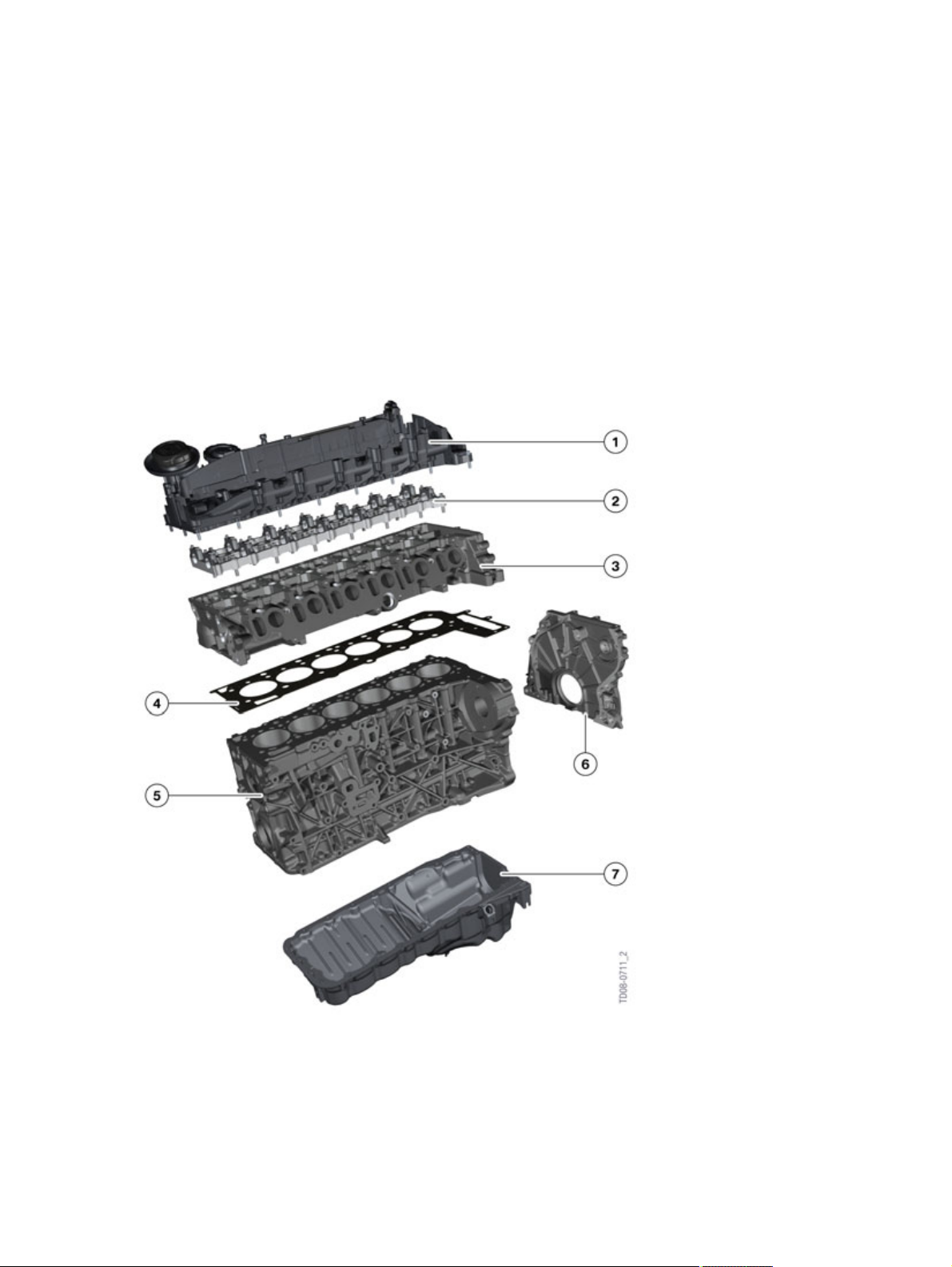
N57TU�engine�block�components
7

N57TU�Engine
2.�Engine�Mechanical
Index Explanation
1 Cylinder�head�cover
2 Camshaft�carrier�plate
3 Cylinder�head
4 Head�gasket
5 Crankcase
6 Timing�case�cover
7 Sump
Loctite�5970�silicone�gasket�is�used�(no�actual�gasket�is�installed)�on�the�sump�and�timing
case�cover�of�the�rear�wheel�drive�535i�models�with�the�N57TU.
The�xDrive�models�with�the�N57TU�use�gaskets�instead�of�the�sealant.
The�special�features�of�the�N57TU�engine�crankcase�are:
• Crankcase�made�of�aluminium.
• Chain�drive�located�on�the�force�transmitting�(flywheel)�side.
• Main�bearing�caps�made�of�sintered�metal.
• Closed-deck�design.
• Main�bearing�pedestal�with�side�walls�that�extend�downwards
and�individual�main�bearing�caps.
• Main�bearing�caps�with�raised-profile�joint�face.
• Dry,�thermally�joined,�cast-iron�cylinder�liners.
Additional�crankcase�rigidity�is�provided�by�a�reinforcing�plate�bolted�to�the�bottom�of�the�crankcase.
That�reinforcing�plate�is�required�to�cope�with�the�lateral�stresses�that�occur�on�the�crankcase
mounting�attachment�points�when�driving�over�a�pothole.�Without�a�reinforcing�plate,�the�crankcase
could�break�at�the�attachment�points�to�the�engine�mounting�bracket�or�at�the�junction�between�the
bearing�pedestal�and�the�side�wall.�The�reinforcing�also�provides�benefits�in�terms�of�noise�reduction.
8

N57TU�Engine
2.�Engine�Mechanical
N57TU�crankcase�with�reinforcing
Index Explanation
1 Crankcase
2 Reinforcing�plate
3 Oil�pump
2.2.�Oil�sump
As�with�the�N47TU�the�engine�oil�sump�gasket�surface�was�converted�to�use�a�silicone�Loctite�gasket
5970.�The�oil�sump�of�the�N57TU�(rear�wheel�drive�model�only)�was�machined�with�chamfer�to
use�the�silicone�gasket.�This�chamfer�is�located�on�the�inside�of�the�flange,�which�serves�as�a�defined
reservoir�for�the�excess�silicone.
9

N57TU�Engine
2.�Engine�Mechanical
Schematic�diagram,�oil�sump�gasket
Index Explanation
A Components�without�silicone�bead
B Components�with�silicone�bead
C Components�bolted�with�silicone�bead
1 Crankcase
2 Silicone�bead
3 Oil�sump�with�chamfer
4 Emergence�of�silicone�through�the�screw�connection�into�the�provided�space
in�the�oil�sump
A�bevel�is�necessary�when�using�a�surface�sealant�to�ensure�that�sealing�compound�that�encroaches�is
deposited�in�a�controlled�manner�in�the�designated�space�where�it�cannot�detach�due�to�splashing�of
oil.
Positioning,�silicone�bead
10
N57TU�Engine
2.�Engine�Mechanical
Index Explanation
1 Oil�sump�sealing�surface
2 Silicone�bead
3 Chamfer�on�inside�of�oil�sump
Loctite�5970�silicone�gasket�is�used�(no�actual�gasket�is�installed)�on�the�sump�and�timing
case�cover�of�the�rear�wheel�drive�535i�models�with�the�N57TU.
The�xDrive�models�with�the�N57TU�use�gaskets�instead�of�the�sealant.
Please�refer�to�the�repair�instructions�for�proper�procedure�and�torque�specifications.
2.3.�Crankshaft
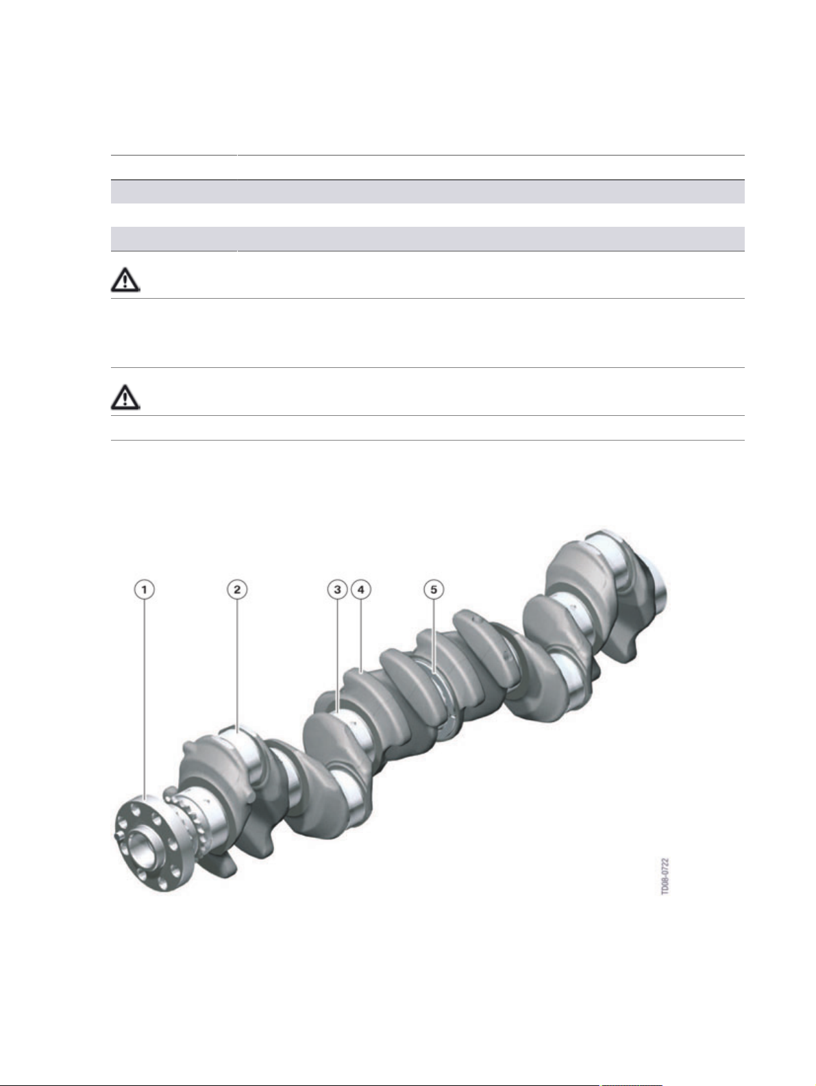
N57TU�crankshaft
11

N57TU�Engine
2.�Engine�Mechanical
Index Explanation
1 Output�flange
2 Rod�bearing�journal�(big-end)
3 Main�bearing�journal
4 Counterweight
5 Axial�bearing�thrust�surface
Counterweights�create�a�balance�of�inertial�forces�around�the�crankshaft�so�as�to�produce�even
rotation�of�the�shaft.�They�are�designed�so�as�to�counterbalance�some�of�the�oscillating�(up-and-down)
inertial�forces�as�well�as�the�rotational�(revolving)�inertial�forces.
The�crankshaft�of�the�N57TU�engine�has�eight�counterweights.
The�N57TU�engine�has�a�forged�crankshaft�made�of�C38modBY.�BY�stands�for�controlled�cooling�from
the�forging�heat�in�the�air�and�makes�for�uniform�joints.�The�material�specifications�are�the�same�as
those�of�the�(M57D30T2)�engine.�In�order�to�achieve�the�required�hardness,�the�crankshaft�is�induction
hardened.�This�forms�an�especially�hard�surface�layer�approximately�1.5�mm�thick.
Advantages�of�forged�crankshafts�compared�to�cast:
• Forged�crankshafts�are�more�rigid�and�have�better�vibrational�properties.
• Especially�when�combined�with�an�aluminium�crankcase,�the�crankshaft�drive�system�must�be
as�rigid�as�possible�because�the�crankcase�itself�is�made�of�material�with�a�lower�rigidity.
• Forged�crankshafts�have�better�wearing�characteristics�at�the�bearing�journals.
In�summary:�the�strength�of�a�forged�crankshaft�is�significantly�greater�than�that�of�a�cast�one.�A�cast
crankshaft�would�not�be�able�to�cope�with�the�loads�to�which�it�is�subjected�in�the�N57TU�engine.
Crankshaft�specifications Unit N57TU
Material C38modBY
Type Forged
Main�bearing�journal
diameter
Rod�bearing�(big-end)
diameter
Crank�pin�off-set [°] 120
Number�of�counterweights 8
Number�of�main�bearings 7
[mm] 55
[mm] 50
Position�of�thrust�bearing 4
Always�refer�to�the�proper�repair�instructions�for�more�information�and�follow�the�special
bearing�classification�procedure�when�servicing�the�crankshaft�and�bearings�on�BMW
engines.
12

N57TU�Engine
2.�Engine�Mechanical
2.4.�Piston
The�pistons�have�been�adapted�to�the�new�requirements�due�to�the�use�of�solenoid�type�injectors.�The
combustion�chamber�and�injector�are�always�harmonized�with�one�another.
2.5.�Connecting�rod
The�shaped�hole�in�the�small�connecting�rod�eye�is�familiar�technology�that�already�features�in�the�N55
and�N47TU�engines.�The�shaped�hole�reduces�edge�load�by�allowing�the�force�acting�on�the�piston�via
the�wrist�pin�to�be�distributed�optimally�across�the�surface�of�the�cylinder�liner.
N57TU�engine,�small�connecting�rod�eye
Index Explanation
1 Bushing
2 Connecting�rod
The�graphic�on�the�following�page�shows�(on�the�left�side)�the�surface�load�for�a�normal�connecting�rod
without�a�shaped�bore.�Due�to�the�pressure�on�the�piston,�most�of�the�force�is�transferred�via�the�wrist
pin�to�the�edges�of�the�small�connecting�rod�eye�bushing.
13

N57TU�Engine
2.�Engine�Mechanical
If�a�shaped�hole�is�introduced�into�the�small�connecting�rod�eye�(graphic�on�the�right)�the�force�is
distributed�across�a�larger�surface�and�the�load�on�the�edge�of�the�bushing�reduces�considerably.�The
force�is�now�transmitted�via�a�larger�surface.
N57TU�engine,�small�connecting�rod�eye
Index Explanation
A Low�surface�load
B High�surface�load
1 Without�shaped�bore
2 With�shaped�bore
2.6.�Cylinder�head
The�distinguishing�technical�features�of�the�N57TU�engine�cylinder�head�are�as�follows:
• Material:�AlSI7MgCu0.5
• Two-piece�cylinder�head�with�camshaft�carrier�plate
• Cross-flow�cooling
• Integral�exhaust�recirculation�channel
• Four�valves�per�cylinder
• Parallel�valve�arrangement�(axes�parallel�with�the�cylinder�axes)
• Tangential�and�swirl�ports
• Reduced�height
14

N57TU�Engine
2.�Engine�Mechanical
N57TU�Cylinder�head�cut�away�with�view�of�the�valvetrain
Index Explanation
1 Camshaft�carrier�plate
2 Hydraulic�valve�clearance�adjuster
3 Glow�plug
4 Exhaust�recirculation�channel
5 Intake�valve
6 Exhaust�valve
7 Valve�guide
8 Valve�spring
9 Roller�cam�follower
10 Exhaust�camshaft
11 Intake�camshaft
The�cylinder�head�of�the�N57TU�engine�largely�matches�the�standards�of�the�current�diesel�engines.�A
special�feature,�however,�is�that�the�cylinder�head�is�comprised�of�two�large�cast�parts.�The�camshafts
are�integrated�inside�their�own�camshaft�carrier.�In�the�case�of�the�N57TU�cylinder�head,�those
two�parts�are�the�main�casting�of�actual�cylinder�head,�and�a�carrier�plate�for�the�camshafts.�Both
camshafts�are�mounted�in�this�camshaft�carrier.�This�design�simplifies�the�manufacturing�process.
15

N57TU�Engine
2.�Engine�Mechanical
2.7.�Cylinder�head�gasket
N57TU�head�gasket
Index Explanation
1 Outer�spring�steel�layer
2 Intermediate�layer�with�welded�sealing�lips
3 Outer�spring�steel�layer
4 Coding�for�identifying�gasket�thickness
The�cylinder�head�gasket�must�be�capable�of�sealing�off�four�zones�from�each�other.
• Combustion�chamber
• Atmosphere
• Engine�oil�passages
• Coolant�passages
A�three-layer�metal�gasket�is�used�on�the�N57TU�engine.
The�cylinder�head�gasket�is�available�to�order�in�three�different�thicknesses,�which�depend�on�the
piston�projection�concerned.�The�thickness�of�the�cylinder�head�gasket�is�indicated�by�holes,�whereby
one�hole�indicates�the�thinnest�and�three�holes�the�thickest�gasket.
16

N57TU�Engine
2.�Engine�Mechanical
2.8.�Crankcase�ventilation
N57TU�crankcase�ventilation
Index Explanation
1 Exhaust�turbocharger
2 Intercooler
3 Pressure�regulation�valve
4 Spring�plates
5 Blow-by�channel
6 Oil�return�channel
7 Air�cleaner
17

N57TU�Engine
2.�Engine�Mechanical
When�the�engine�is�running,�blow-by�gases�escape�from�the�cylinders�into�the�crankshaft�cavity.�Those
blow-by�gases�contain�unburned�fuel�and�all�the�constituents�of�the�exhaust.�In�the�crankshaft�cavity,
they�mix�with�the�engine�oil�that�is�present�in�the�form�of�oil�vapor.
The�extent�of�blow-by�is�dependent�on�load.�Pressure�is�created�inside�the�crankshaft�cavity�and,�due
to�the�motion�of�the�pistons,�is�also�dependent�on�engine�speed.�This�overpressure�is�also�present�in
all�spaces�that�connect�to�the�crankshaft�cavity�(e.g.�oil�return,�chain�cavity,�etc.)�and�if�not�released
would�force�oil�out�through�the�sealed�joints.
The�crankcase�venting�system�prevents�that�from�happening.�It�channels�blow-by�gases�that�are
largely�free�of�engine�oil�into�the�filtered-air�pipe�upstream�of�the�turbocharger.�The�separated�engine
oil�droplets�work�their�way�back�into�the�sump�through�an�oil�return�pipe.�The�crankcase�venting
system�also�ensures�that�excess�pressure�is�not�created�in�the�crankcase.
The�N57�engine�is�equipped�with�a�vacuum�controlled�crankcase�venting�system�with�a�regulated
negative�pressure�of�about�38�mbar�(maintained).
Pre-loaded�metal�spring�plates�(known�as�variable-aperture�separators)�regulate�the�air�mass�flow�rate,
thereby�ensuring�optimum�oil�separation�from�the�blow-by�gas�in�all�engine�operating�situations.
A�negative�pressure�is�created�in�the�purified�air�pipe�due�to�the�suction�of�the�exhaust�turbocharger.
As�a�result�of�the�pressure�difference�relative�to�the�crankcase,�the�blow-by�gas�is�drawn�into�the
cylinder�head.
In�the�cylinder�head,�the�blow-by�gas�first�enters�the�plenum�chamber.�The�purpose�of�the�plenum
chamber�is�to�ensure�that�no�oil�spray,�e.g.�from�the�camshafts,�enters�the�crankcase�venting�system.
Thus,�a�degree�of�initial�separation�already�takes�place�in�the�plenum�chamber.�The�oil�that�deposits�on
the�wall�here�flows�back�into�the�cylinder�head.
The�blow-by�gas�flows�from�the�plenum�chamber�to�the�spring-plate�separators.�The�spring�plates�are
forced�open�by�the�flow�of�blow-by�gas�so�that�the�blow-by�gas�passes�through.�Since�the�aperture
size�is�relatively�small,�the�flow�velocity�of�the�blow-by�gas�is�accelerated.�And�since�the�blow-by�gas
flow�is�then�deflected�by�about�180°,�the�fluid�contained�in�the�blow-by�gas�is�thrown�against�the
surrounding�walls�by�centrifugal�force�and�runs�down�them�into�a�drain�channel�and�back�into�the
sump.�The�spring�plates�are�opened�to�a�greater�(B)�or�lesser�(A)�degree�depending�on�the�quantity
of�blow-by�gas�so�that�optimum�oil�separation�is�achieved�regardless�of�blow-by�gas�flow�rate.�The
spring-plate�separator�has�brought�about�an�improvement�in�the�separation�quality�under�all�operating
conditions�but�especially�at�low�blow-by�gas�flow�rates.�The�cleaned�blow-by�gas�flows�through�the
pressure�regulating�valve�and�into�the�filtered-air�pipe�upstream�of�the�turbocharger.
18

N57TU�Engine
2.�Engine�Mechanical
N57TU�oil�separation�in�the�cylinder�head
index Explanation
A Low�blow-by�gas�flow�rate
B High�blow-by�gas�flow�rate
1 Oil�droplets
2 Air�flow
3 Blow-by�gas�flow
4 Spring�plate
5 Channel�to�pressure�regulating�valve
6 Pressure�regulating�valve
7 Blow-by�gas�feed�into�filtered-air�pipe
8 Oil�return�channel
9 Blow-by�gas�inflow
10 Plenum�chamber
19

N57TU�Engine
2.�Engine�Mechanical
2.9.�Camshaft�drive�system
The�special�features�and�specifications�of�the�chain�drive�system�on�the�N57TU�engine�are�as�follows:
• Chain�drive�system�mounted�on�flywheel�side�of�engine.
• Two-section�system�for�driving�the�high�pressure�pump�and�camshafts.
• Use�of�simplex�sleeve-type�chains.
• Oil/vacuum�pump�driven�by�second�chain.
• Plastic�tensioning�and�guide�rails.
• Hydraulic�chain�tensioners.
As�on�the�N47TU�engine,�the�chain�drive�system�on�the�N57TU�engine�is�mounted�on�the�flywheel
end,�i.e.�the�rear,�of�the�engine.�Due�to�the�fact�that�the�timing�gear�is�mounted�at�the�rear,�the�engine
is�lower�at�the�front.�This�is�of�benefit�for�the�passive�safety�features�for�minimizing�pedestrian�impact
severity.�It�creates�more�space�between�the�engine�and�the�hood.�Thus,�in�the�event�of�a�crash,�there
is�more�room�for�the�hood�to�deform�and�absorb�the�impact�therefore�minimizing�the�injury�to�the
pedestrian.�Another�benefit�is�that�rotational�vibrations�are�significantly�reduced�due�to�the�inertial
mass�of�the�transmission�at�this�end.�This�results�in�an�enormous�relief�of�load�on�the�chain�drive.�One
of�the�consequences�of�this�arrangement�is�that�various�components�are�installed�in�unconventional
locations�or�positions,�e.g.�oil�pump,�camshaft�sensor,�etc.
N57TU�chain�drive
20

N57TU�Engine
2.�Engine�Mechanical
Index Explanation
1 Upper�chain
2 Exhaust�camshaft�gear
3 Upper�chain�tensioner
4 Upper�tensioning�rail
5 Lower�chain�tensioner
6 Lower�tensioning�rail
7 Crankshaft
8 Oil�vacuum/pump�sprocket
9 Oil�vacuum/pump�chain
10 Lower�chain�guide�rail
11 Oil�spray�nozzle
12 High-pressure�pump�sprocket
13 Lower�chain
14 Upper�guide�rail
15 Intake�camshaft�sprocket
2.10.�Camshafts�and�timing
The�N57TU�engine�is�fitted�with�the�now�familiar�composite�camshafts.�They�are�made�using�the
Presta�method�in�common�with�the�camshafts�on�all�BMW�diesel�engines.
N57TU�camshaft
21
N57TU�Engine
2.�Engine�Mechanical
Index Explanation
1 Cam
2 Shaft
3 Gear�and�camshaft�sensor�wheel
The�intake�camshaft�is�driven�by�a�sprocket�which�is�chain-driven�by�the�crankshaft.�The�exhaust
camshaft�is�driven�by�direct�gear-to-gear�transmission�from�the�intake�camshaft.�The�camshaft�gears
are�integral�components�of�the�camshafts�and�are�permanently�attached�to�them.�Markings�on�the
camshaft�gears�facilitate�the�correct�positioning�of�the�camshafts�relative�to�one�another�when�fitting.
The�intake�camshaft�gear�also�has�raised�lugs�so�that�it�serves�simultaneously�as�the�reluctor�ring�for
the�camshaft�sensor.�The�twin-flatted�collar�for�accepting�the�special�tool�for�positioning�the�camshaft
relative�to�the�crankshaft�when�fitting�is�integral�with�the�camshaft.�On�the�N57TU�engine,�the�special
tool�is�only�placed�on�the�exhaust�camshaft.
N57TU�timing�gear�alignment
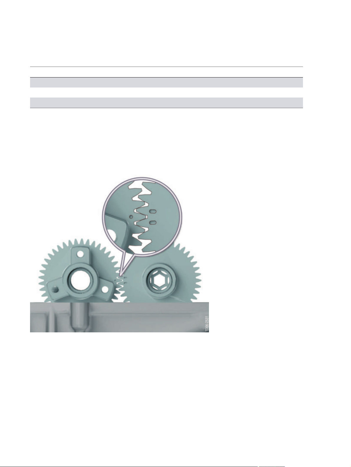
The�camshaft�sprocket�is�bolted�to�the�camshaft�gear�of�the�intake�camshaft.�Slots�are�provided�for
adjusting�the�valve�timing.�A�new�feature�is�that�the�sprocket�can�be�bolted�in�place�without�turning�the
camshaft�out�of�position.�To�that�end,�the�three�bolts�are�not�spaced�evenly�120°�apart�(see�graphic
above).�To�brace�the�camshaft�when�fitting�the�sprocket,�an�Allen-key�socket�in�the�center�of�the
camshaft�gear�on�the�exhaust�camshaft�is�used.
22

N57TU�Engine
2.�Engine�Mechanical
2.10.1.�Timing
The�N57TU�engine�timing�has�remained�the�same�when�compared�to�the�N47TU�engine.
N57TU�engine,�timing�diagram
N57TU�intake N57TU�exhaust
Valve�diameter [mm] 27.2 24.6
Max.�valve�lift [mm] 8.5 8.5
Spread [crankshaft
degrees]
Valve�opens [crankshaft
degrees]
Valve�closes [crankshaft
degrees]
Valve�opening�period [crankshaft
degrees]
100 105
352.4 140.7
567.1 363.9
214.7 223.1
23
N57TU�Engine
3.�Belt�Drive
The�layout�of�the�belt�drive�and�assemblies�has�been�redesigned.
3.1.�N57�engine
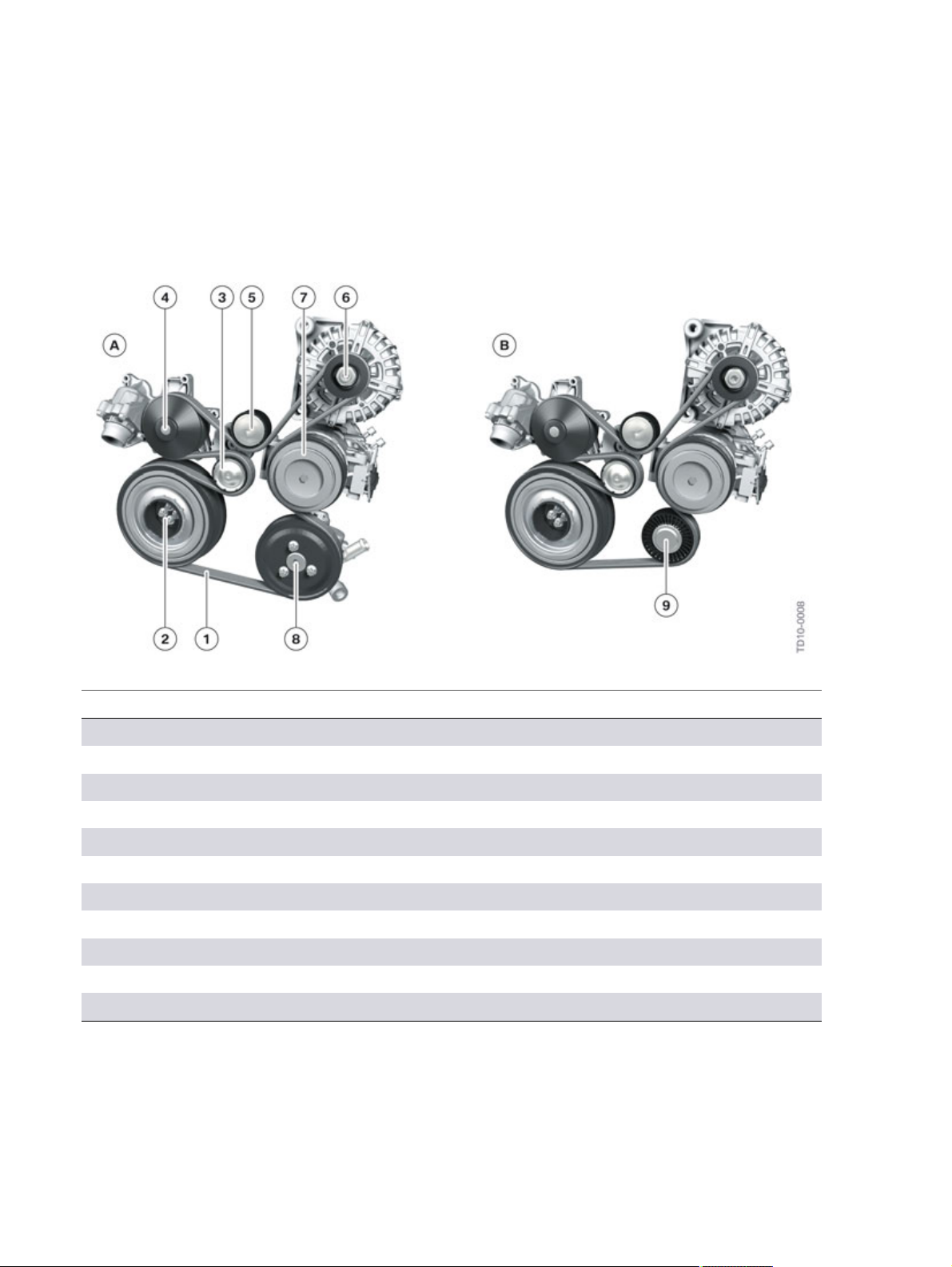
N57�engine,�belt�drive�variants
Index Explanation
A With�air�conditioning�and�hydraulic�steering
B With�air�conditioning�and�electromechanical�power�steering
1 Drive�belt,�double-sided
2 Torsional�vibration�damper
3 Tensioning�pulley
4 Coolant�pump
5 Deflecting�element
6 Alternator
7 Air�conditioning�compressor
8 Power�steering�pump
9 Deflecting�element
24
 Loading...