

BMW N55 User Manual

Tab l e of Contents
N55 Engine
Subject Page
Introduction . . . . . . . . . . . . . . . . . . . . . . . . . . . . . . . . . . . . . . . . . . . . . . . . . .5
Engine Components/Systems Overview . . . . . . . . . . . . . . . . . . . . . . . . . . .6
Te ch n i ca l Data . . . . . . . . . . . . . . . . . . . . . . . . . . . . . . . . . . . . . . . . . . . . . . . . .8
Full Load Diagram . . . . . . . . . . . . . . . . . . . . . . . . . . . . . . . . . . . . . . . . . . . .9
Current Models . . . . . . . . . . . . . . . . . . . . . . . . . . . . . . . . . . . . . . . . . . . . . . .10
Engine Designation and Engine Identification . . . . . . . . . . . . . . . . . . . . .11
Engine Designation . . . . . . . . . . . . . . . . . . . . . . . . . . . . . . . . . . . . . . . . .11
Breakdown of N55 Engine Designation . . . . . . . . . . . . . . . . . . . . . . . .12
Engine Identification . . . . . . . . . . . . . . . . . . . . . . . . . . . . . . . . . . . . . . . .12
Engine Components . . . . . . . . . . . . . . . . . . . . . . . . . . . . . . . . . . . . . . . . .14
Engine Housing . . . . . . . . . . . . . . . . . . . . . . . . . . . . . . . . . . . . . . . . . . . . . . .14
Engine Block . . . . . . . . . . . . . . . . . . . . . . . . . . . . . . . . . . . . . . . . . . . . . . .14
Crankcase and Bedplate . . . . . . . . . . . . . . . . . . . . . . . . . . . . . . . . . . . . .14
Crankshaft . . . . . . . . . . . . . . . . . . . . . . . . . . . . . . . . . . . . . . . . . . . . . . . . . . . .17
Crankshaft Main Bearings . . . . . . . . . . . . . . . . . . . . . . . . . . . . . . . . .17
Pistons and Rings . . . . . . . . . . . . . . . . . . . . . . . . . . . . . . . . . . . . . . . . . . . . .18
Connecting Rod and Bearings . . . . . . . . . . . . . . . . . . . . . . . . . . . . . . . . . .19
Oil Pan . . . . . . . . . . . . . . . . . . . . . . . . . . . . . . . . . . . . . . . . . . . . . . . . . . . . . . .22
Electrionic Volume-controlled Oil Pump . . . . . . . . . . . . . . . . . . . . . . . . . .23
Oil Pump and Pressure Control . . . . . . . . . . . . . . . . . . . . . . . . . . . . . . .24
Oil Supply . . . . . . . . . . . . . . . . . . . . . . . . . . . . . . . . . . . . . . . . . . . . . . . . . . . .27
Oil Filtration and Oil Cooling . . . . . . . . . . . . . . . . . . . . . . . . . . . . . . . . . .30
Oil Spray Nozzles . . . . . . . . . . . . . . . . . . . . . . . . . . . . . . . . . . . . . . . . . . .31
Oil Pressure . . . . . . . . . . . . . . . . . . . . . . . . . . . . . . . . . . . . . . . . . . . . . . . .31
Oil Level . . . . . . . . . . . . . . . . . . . . . . . . . . . . . . . . . . . . . . . . . . . . . . . . . . .31
Oil Return . . . . . . . . . . . . . . . . . . . . . . . . . . . . . . . . . . . . . . . . . . . . . . . . . .31
Cylinder Head . . . . . . . . . . . . . . . . . . . . . . . . . . . . . . . . . . . . . . . . . . . . . . . . .32
Cylinder Head Cover . . . . . . . . . . . . . . . . . . . . . . . . . . . . . . . . . . . . . . . .33
Crankcase Ventilation . . . . . . . . . . . . . . . . . . . . . . . . . . . . . . . . . . . . . . . . . .34
Naturally Aspirated Mode . . . . . . . . . . . . . . . . . . . . . . . . . . . . . . . . . . . .34
Boost Mode . . . . . . . . . . . . . . . . . . . . . . . . . . . . . . . . . . . . . . . . . . . . . . . .36
Valve train . . . . . . . . . . . . . . . . . . . . . . . . . . . . . . . . . . . . . . . . . . . . . . . . . . . . .39
Intake and Exhaust Valves . . . . . . . . . . . . . . . . . . . . . . . . . . . . . . . . . . . .40
Valve Springs . . . . . . . . . . . . . . . . . . . . . . . . . . . . . . . . . . . . . . . . . . . . . . .40
Initial Print Date: 02/10
Revision Date:

Subject Page
Camshafts . . . . . . . . . . . . . . . . . . . . . . . . . . . . . . . . . . . . . . . . . . . . . . . . . . . .41
Valve Timing . . . . . . . . . . . . . . . . . . . . . . . . . . . . . . . . . . . . . . . . . . . . . . .42
VANOS System . . . . . . . . . . . . . . . . . . . . . . . . . . . . . . . . . . . . . . . . . . . . . . .43
Overview . . . . . . . . . . . . . . . . . . . . . . . . . . . . . . . . . . . . . . . . . . . . . . . . . . .44
VANOS Solenoid Valves . . . . . . . . . . . . . . . . . . . . . . . . . . . . . . . . . . . . .45
Cam Sensor Wheels . . . . . . . . . . . . . . . . . . . . . . . . . . . . . . . . . . . . . . . .45
Valve tronic III . . . . . . . . . . . . . . . . . . . . . . . . . . . . . . . . . . . . . . . . . . . . . . . . . .46
Phasing . . . . . . . . . . . . . . . . . . . . . . . . . . . . . . . . . . . . . . . . . . . . . . . . . . . .46
Masking . . . . . . . . . . . . . . . . . . . . . . . . . . . . . . . . . . . . . . . . . . . . . . . . . . .46
Combustion Chamber Geometry . . . . . . . . . . . . . . . . . . . . . . . . . . . . .49
Valve Lift Adjustment Overview . . . . . . . . . . . . . . . . . . . . . . . . . . . . . . .50
Valve tronic Servomotor . . . . . . . . . . . . . . . . . . . . . . . . . . . . . . . . . . .52
Function . . . . . . . . . . . . . . . . . . . . . . . . . . . . . . . . . . . . . . . . . . . . . . . . .52
Belt Drive and Auxiliarly Components . . . . . . . . . . . . . . . . . . . . . . . . . . . .53
Vibration Damper . . . . . . . . . . . . . . . . . . . . . . . . . . . . . . . . . . . . . . . . . . . . . .54
Air Intake and Exhaust System . . . . . . . . . . . . . . . . . . . . . . . . . . . . . . . . . .56
Air Intake System . . . . . . . . . . . . . . . . . . . . . . . . . . . . . . . . . . . . . . . . . . .56
Intake Manifold . . . . . . . . . . . . . . . . . . . . . . . . . . . . . . . . . . . . . . . . . . . . .59
Fuel Ta n k Ventilation System . . . . . . . . . . . . . . . . . . . . . . . . . . . . . . . . .60
Exhaust Manifold . . . . . . . . . . . . . . . . . . . . . . . . . . . . . . . . . . . . . . . . . . .61
Tu rb oc h ar ge r . . . . . . . . . . . . . . . . . . . . . . . . . . . . . . . . . . . . . . . . . . . . . . .62
Function of the twin scroll turbocharger . . . . . . . . . . . . . . . . . . . .65
Diverter valve . . . . . . . . . . . . . . . . . . . . . . . . . . . . . . . . . . . . . . . . . . . .65
Catalytic Converter . . . . . . . . . . . . . . . . . . . . . . . . . . . . . . . . . . . . . . . . . .66
Exhaust System . . . . . . . . . . . . . . . . . . . . . . . . . . . . . . . . . . . . . . . . . . . .67
Vacuum System . . . . . . . . . . . . . . . . . . . . . . . . . . . . . . . . . . . . . . . . . . . . . . .68
Vacuum Pump . . . . . . . . . . . . . . . . . . . . . . . . . . . . . . . . . . . . . . . . . . . . . .69
Fuel Injection . . . . . . . . . . . . . . . . . . . . . . . . . . . . . . . . . . . . . . . . . . . . . . . . .71
Fuel Pressure Sensor . . . . . . . . . . . . . . . . . . . . . . . . . . . . . . . . . . . . . . .72
High Pressure Fuel Pump . . . . . . . . . . . . . . . . . . . . . . . . . . . . . . . . . . . .73
Fuel Injectors . . . . . . . . . . . . . . . . . . . . . . . . . . . . . . . . . . . . . . . . . . . . . . .74
Cooling System . . . . . . . . . . . . . . . . . . . . . . . . . . . . . . . . . . . . . . . . . . . . . . .75
Components . . . . . . . . . . . . . . . . . . . . . . . . . . . . . . . . . . . . . . . . . . . . . . .77
N55, Cooling System Components . . . . . . . . . . . . . . . . . . . . . . . . . . .77
Oil Cooler . . . . . . . . . . . . . . . . . . . . . . . . . . . . . . . . . . . . . . . . . . . . . . .79
Coolant Passages . . . . . . . . . . . . . . . . . . . . . . . . . . . . . . . . . . . . . . . . . . .80
Engine Electrical System . . . . . . . . . . . . . . . . . . . . . . . . . . . . . . . . . . . . .82
Circuit Diagram . . . . . . . . . . . . . . . . . . . . . . . . . . . . . . . . . . . . . . . . . . . . . . . .83
Engine Cooling Circuit Diagram . . . . . . . . . . . . . . . . . . . . . . . . . . . . . . .85
Digital Motor Electronics (DME/ECM) . . . . . . . . . . . . . . . . . . . . . . . . . . . .87
Digital Motor Electronics Circuit Diagram . . . . . . . . . . . . . . . . . . . . . .88
N55, MEVD17.2 Circuit Diagram . . . . . . . . . . . . . . . . . . . . . . . . . . . . .88
Functions . . . . . . . . . . . . . . . . . . . . . . . . . . . . . . . . . . . . . . . . . . . . . . . . . .90

Subject Page
Fuel supply system . . . . . . . . . . . . . . . . . . . . . . . . . . . . . . . . . . . . . .90
Fuel quantity control . . . . . . . . . . . . . . . . . . . . . . . . . . . . . . . . . . . . .90
Boost pressure control . . . . . . . . . . . . . . . . . . . . . . . . . . . . . . . . . . .90
Engine cooling . . . . . . . . . . . . . . . . . . . . . . . . . . . . . . . . . . . . . . . . . .91
System Protection . . . . . . . . . . . . . . . . . . . . . . . . . . . . . . . . . . . . . . .92
Crankshaft Sensor . . . . . . . . . . . . . . . . . . . . . . . . . . . . . . . . . . . . . . . . . .92
Ignition Coil . . . . . . . . . . . . . . . . . . . . . . . . . . . . . . . . . . . . . . . . . . . . . . . .94
Oil Pressure Sensor . . . . . . . . . . . . . . . . . . . . . . . . . . . . . . . . . . . . . . . . .95
Oxygen Sensors . . . . . . . . . . . . . . . . . . . . . . . . . . . . . . . . . . . . . . . . . . . .95
Oxygen sensor before catalytic converter . . . . . . . . . . . . . . . . . . .96
Oxygen sensor after catalytic converter . . . . . . . . . . . . . . . . . . . . .96
Hot-film air mass meter . . . . . . . . . . . . . . . . . . . . . . . . . . . . . . . . . . .97
High Pressure Fuel Injector Valve . . . . . . . . . . . . . . . . . . . . . . . . . . . . .97
Function . . . . . . . . . . . . . . . . . . . . . . . . . . . . . . . . . . . . . . . . . . . . . . . . .98
Service Information . . . . . . . . . . . . . . . . . . . . . . . . . . . . . . . . . . . . . . . . . .99
Cylinder Head . . . . . . . . . . . . . . . . . . . . . . . . . . . . . . . . . . . . . . . . . . . . . . . . .99
Cylinder Head Cover . . . . . . . . . . . . . . . . . . . . . . . . . . . . . . . . . . . . . . . . . . .99
Fuel Injectors . . . . . . . . . . . . . . . . . . . . . . . . . . . . . . . . . . . . . . . . . . . . . . . . .99
Ignition Coils . . . . . . . . . . . . . . . . . . . . . . . . . . . . . . . . . . . . . . . . . . . . . . . . .100

N55 Engine
Model: All with N55
Production: From Start of Production
After completion of this module you will be able to:
• Describe the features of the N55B30M0 engine
• Describe the specifications of the N55 engine
• Identify the internal and external components of the N55 engine
• Understand the function of the crankcase ventilation on the N55 engine
• Understand the function of the electronic volume control oil pump
4
N55 Engine
Introduction
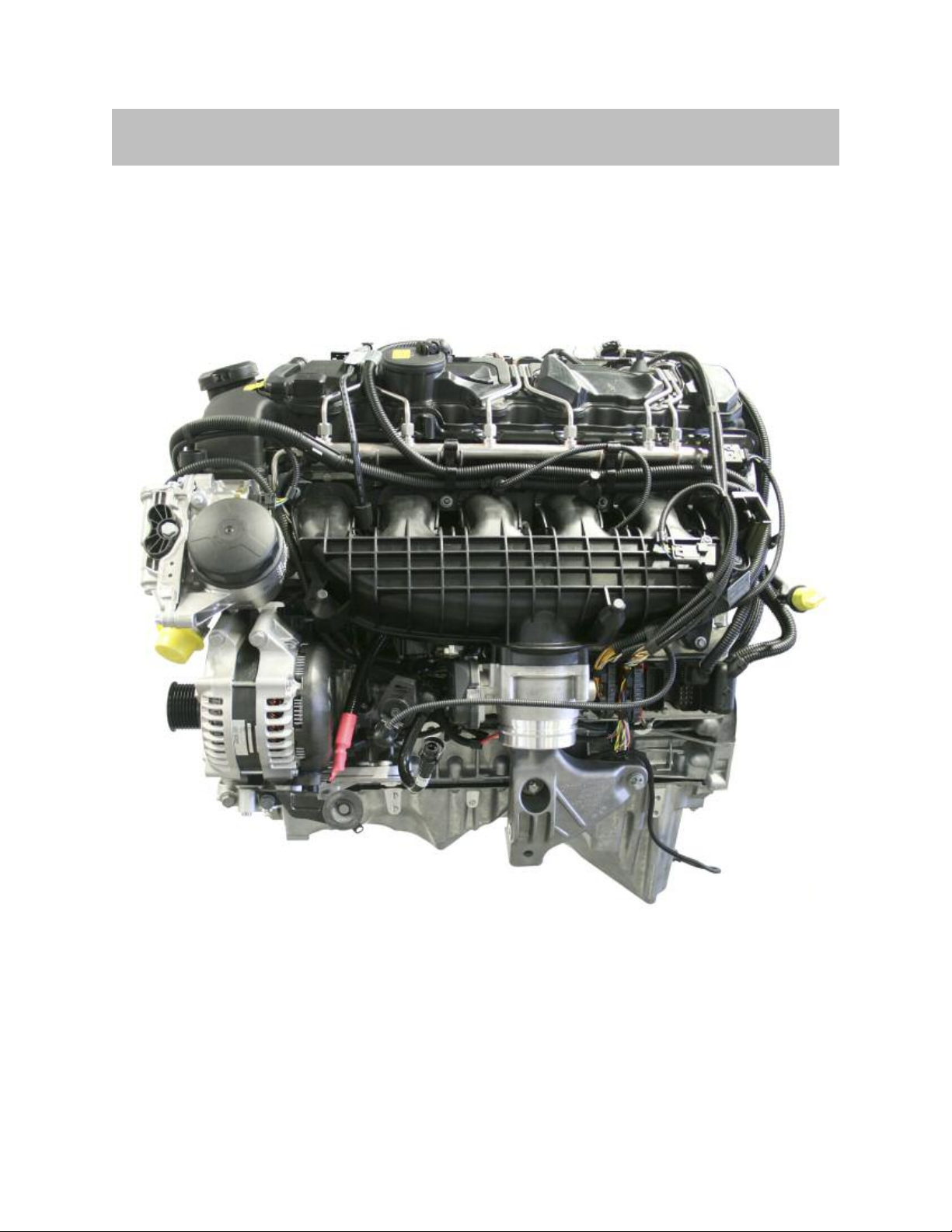
The N55 engine is the successor to the N54. Re-engineering and modifications have
made it possible to now use only one exhaust turbocharger. Against the backdrop of
reduced costs and improved quality, the technical data have remained virtually the same.
N55 Engine
N55 Engine
5

Engine Components/Systems Overview
The following provides an overview of the features of the N55 engine:
Crankcase:
• Large longitudinal ventilation holes inter-connect the crankcase lower chambers
and relieve unwanted crankcase pressure between cylinders.
• Modified oil galleries enhance the supply of oil to vacuum pump.
Crankshaft: Is light weight design and has an asymmetric counterweight arrangement.
Pistons and connecting rods:
• A specially formed bushing/bore in small end of the connecting rods evenly
distributes the force of the pistons on the power stroke.
• Lead-free bearing shells are installed on the big-end of the connecting rods.
Cylinder head:
• Specially designed water passages intergraded into the cylinder head enhance
injector cooling.
• The combustion chambers are machined to work in conjuction with the Va lvetronic
III system with regard to promoting air turbulence and mixture formation.
Crankcase ventilation:
• In contrast to the N54, the N55 crankcase ventilation does not use cyclone
separators.
• The cylinder and head cover have integrated blow-by passages that connect the
crankcase ventilation directly to the intake ports.
VANOS:
• The N55 VANOS oil passages are simplified compared to the N54 engine.
• The solenoid valves have integrated non-return valve and 3 screen filters.
• The VANOS units are of a lightweight design for increased adjustment speed
and have a reduced susceptibility to soiling.
Valvetrain:
• The N55 is the first BMW turbo engine to incorporate Valvetronic.
• The valvetrain is a new designed that combines Valvetronic III with Double VANOS.
• With Valvetronic III the 3rd generation brushless servomotor is introduced.
• The position detection sensor of eccentric shaft is now integrated in the servomotor.
6
N55 Engine

Oil supply:
• An enhanced and simplified oil circuit design is used.
• The inlet pipe, oil deflector, and oil collector are combined in one component.
• Oil pump uses a Duroplast slide valve and it is electronically controlled based on
a characteristic map within the engine management.
Forced induction:
• The N55 uses a single twin scroll turbocharger with vacuum operated,
electronically controlled wastegate valve.
• The electric diverter valve is intergraded into the turbocharger compressor housing.
Air intake and exhaust system:
• Air intake system is similar in configuration as the N54 with the exception of the
intake manifold and the use of a single turbo.
• The intercooler is an air to air type mounted in the lower area of the front bumper
cover.
• The exhaust system uses no underbody catalytic converter.
Vacuum system:
• The N55 engine has a two-stage vacuum pump as on the N54.
• The vacuum system has the vacuum reservoir built into the cylinder head cover.
Fuel injection:
• HDE (high pressure fuel injection) system is installed on the N55.
• The HDE system uses solenoid valve fuel injectors instead of the piezoelectric
type used on HPI.
• The high pressure pump and pressure sensors are similar in design and function
in both the HDE and HPI systems.
Digital Motor Electronics (DME):
• The DME is mounted on the intake manifold and cooled by intake air.
• The location of the DME facilitates the installation of the N55 engine in several
current BMW platforms/models.
N55 Engine
7

Te chni c a l Data
Configuration
Cylinder capacity
Bore/stroke
Power output at
engine speed
Power output per liter
Tor qu e at engine speed
Compression ratio
Valves/cylinder
Fuel consumption,
EU combined
CO2 emission
Digital Motor Electronics
Exhaust emission
legislation, US
Unit
[cm³] 2979 2979
[mm] 84.0/89.6 84.0/89.6
[kW/bhp] [rpm] 225/306 5800 - 6250 225/306 5800 - 6400
[kW/l] 75.53 75.53
[Nm] [rpm] 400 1300 - 5000 400 1200 - 5000
[ε]
[l/100 km] 10.9 8.9
g/km 262 209
N54B30O0 (E71/X6
xDrive35i)
6 inline 6 inline
10.2 10.2
4 4
MSD81 MEVD17.2
ULEV ULEV II
N55B30M0
(F07/535i)
Engine oil specification
Top speed
Acceleration
0 - 100 km/h/62mph
Veh icle curb weight DIN/EU
* = Electronically governed
8
N55 Engine
BMW Longlife-01 BMW
Longlife-01 FE BMW
Longlife-04
[km/h] 240 250
[s] 6.7 6.3
[kg] 2070/2145 1940/2015
-
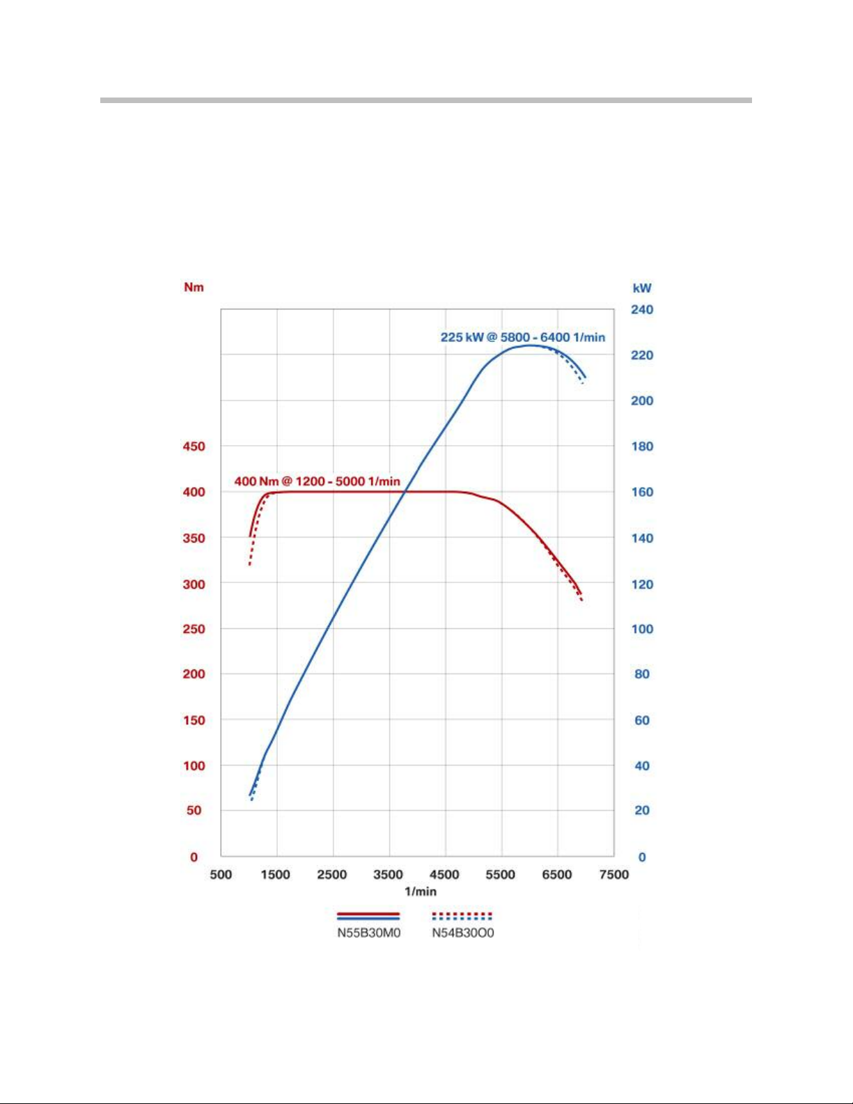
Full Load Diagram
Compared to its predecessor, the N55 engine is characterized by lower fuel consumption
with the same power output and torque data.
Full load diagram E90 335i with N54B30O0 engine
compared to the F07 535i with N55B30M0 engine
N55 Engine
9

Current Models
N54B30O0 engine variants
Model Vers io n Series
135i
335i
335i xDrive
335is
Z4 sDrive35i
Z4
sDrive35is
US E82, E88 2979 89.6/84.0
US
US E90, E92 2979 89.6/84.0
US E92, E93 2979 89.6/84.0
US E89 2979 89.6/84.0
US E89 2979 89.6/84.0
E90, E92,
E93
Displacement in
cm³
2979 89.6/84.0
Stroke/
bore in
mm
Power
output in
kW/bhp at
rpm
300 SAE hp
5800 - 6250
300 SAE hp
5800 - 6250
300 SAE hp
5800 - 6250
320 SAE hp
5800 - 6250
300 SAE hp
5800 - 6250
335 SAE hp
5800 - 6250
To r q u e i n
Nm at rpm
407
(300 ft-lbs)
1400 - 5000
407
(300 ft-lbs)
1400 - 5000
407
(300 ft-lbs)
1400 - 5000
450
(332 ft-lbs)
1400 - 5000
407
(300 ft-lbs)
1400 - 5000
450
(332/369 ft-lbs)
*1400 - 5000
407
(300 ft-lbs)
1400 - 5000
407
(300 ft-lbs)
1400 - 5000
407
(300 ft-lbs)
1400 - 5000
450
(330 ft-lbs)
1600 - 4500
535i
535i xDrive
X6 xDrive35i
740i
US E60 2979 89.6/84.0
US E60, E61 2979 89.6/84.0
US E71 2979 89.6/84.0
US F01, F02 2979 89.6/84.0
300 SAE hp
5800 - 6250
300 SAE hp
5800 - 6250
300 SAE hp
5800 - 6250
315 SAE hp
5800 - 6250
* The enhanced engine management system of the BMW Z4 sDrive35is and the 335is include
an electronically controlled overboost function to briefly increase torque under full load by
another 37 ft-lbs. This temporary torque peak of 369 ft-lbs gives the car a significant increase
in acceleration for approximately 5 seconds.
10
N55 Engine

Engine Designation and Engine Identification
Engine Designation
This training material describes the N55B30M0 in detail.
In the technical documentation, the engine designation is used for unique identification of
the engine. In the technical documentation you will also find the abbreviated engine designation, i.e. N55, that only indicates the engine type.
Item Meaning Index / explanation
M, N = BMW Group
1 Engine developer
2 Engine type
P = BMW Motorsport
S = BMW M mbH
W = Non-BMW engines
1 = R4 (e.g. N12)
4 = R4 (e.g. N43)
5 = R6 (e.g. N55)
6 = V8 (e.g. N63)
7 = V12 (e.g. N73)
8 = V10 (e.g. S85)
3 Change to the basic engine concept
4
5 Displacement in liters 1 = 1 liter (whole number of liters)
6 Displacement in 1/10 liter 8 = 0.8 liter (tenth of liter)
7 Performance class
8 Revision relevant to approval
Working method or fuel type and
possibly installation position
0 = basic engine
1 – 9 = changes, e.g. combustion process
B = Gasoline, longitudinal installation
D = Diesel, longitudinal installation
H = Hydrogen
K = Smallest
U = Lower
M = Middle
O = Upper (standard)
T = To p
S = Super
0 = New development
1 – 9 = Revision
11
N55 Engine

Breakdown of N55 Engine Designation
Index Explanation
N
5
5
B
30
M
0
Engine with direct injection, Val vet ron ic and exhaust turbocharger
BMW Group Development
Straight 6 engine
Gasoline engine, longitudinal
3.0-liter capacity
Medium performance class
New development
Engine Identification
The engines are marked on the crankcase with an engine identification code for unique
identification. This engine identifier is also required for approval by the authorities. The
N55 engine further develops this identification system and the code has been reduced
from previously eight to seven characters. The engine serial number can be found under
the engine identifier on the engine. To g e th e r with the engine identifier, this consecutive
number enables unique identification of each individual engine.
Item Meaning Index / explanation
M, N = BMW Group
1
2
3
Change to the basic engine concept
4
5
6
7
Typ e test concerns (changes that
Engine developer
Engine type
Working method or fuel type and
possibly installation position
Displacement in liters 1 = 1 liter (whole number of liters)
Displacement in 1/10 liter 8 = 0.8 liter (tenth of liter)
require a new type test)
P = BMW Motorsport
S = BMW M GmbH
W = Non-BMW engines
1 = R4 (e.g. N12)
4 = R4 (e.g. N43)
5 = R6 (e.g. N55)
6 = V8 (e.g. N63)
7 = V12 (e.g. N73)
8 = V10 (e.g. S85)
0 = basic engine
1 – 9 = changes, e.g. combustion process
B = Gasoline, longitudinal installation
D = diesel, longitudinal installation
H = hydrogen
A = Standard
B – Z = Depending on requirement, e.g. RON 87
12
N55 Engine
N55 engine, engine identification and engine serial number
Index Explanation
08027053
N
5
5
B
30
A
Change to basic engine concept, turbocharging, Valvetronic , direct fuel injection
Operating principle or fuel supply and installation position, petrol engine longitudinal
Individual consecutive engine serial number
Engine developer, BMW Group
Engine type, straight 6
Displacement in 1/10 liter, 3 liter
Typ e approval requirements, standard
13
N55 Engine

Engine Components
Engine Housing
The engine housing consists of the engine block (crankcase and bedplate), cylinder
head, cylinder head cover, oil pan and gaskets.
Engine Block
The engine block is made from an aluminum die-casting and consists of the crankcase
with bedplate.
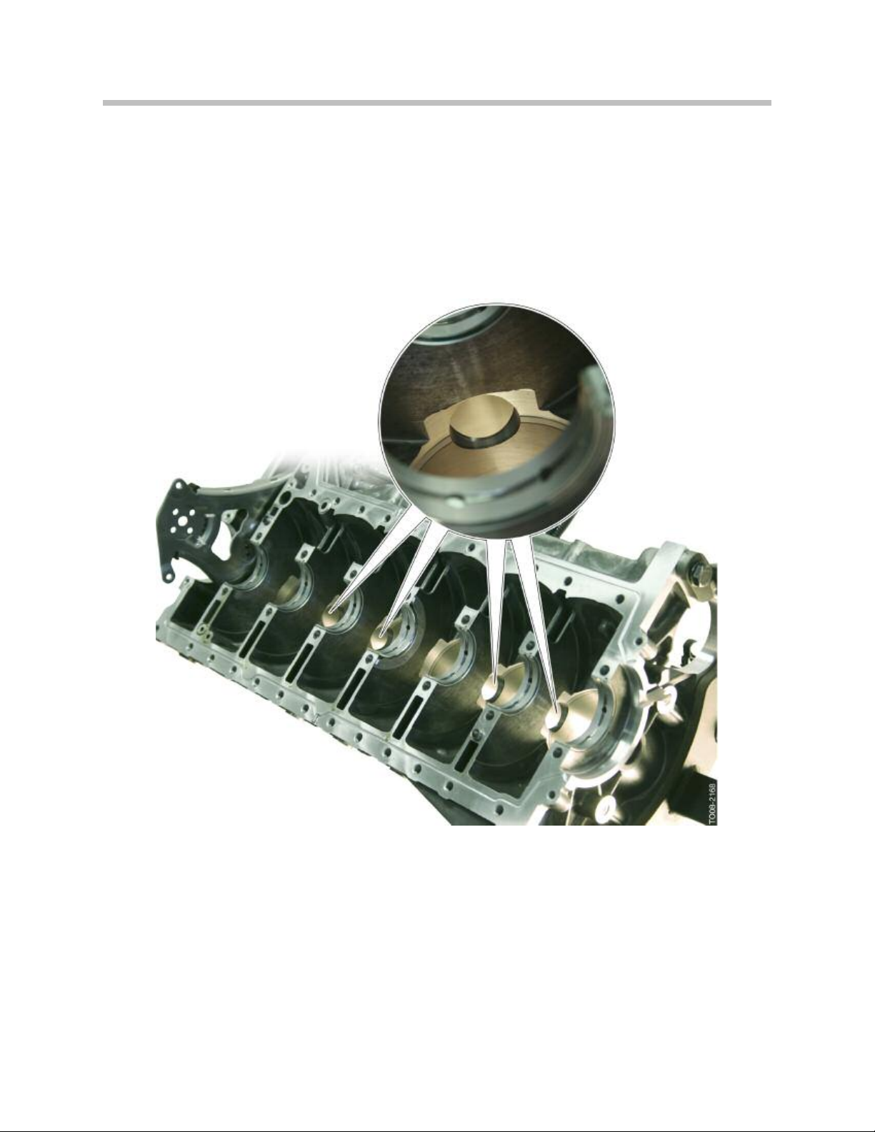
Crankcase and Bedplate
The crankcase features cast iron cylinder liners (2). A new feature is that the webs
between two cylinders on the deck of the block now have a grooved cooling passage
(3). Coolant can flow along these grooves from one side of the crankcase to the other,
thus enhancing cooling of this area.
Five oil return ducts on the exhaust side (4) now permit oil to return from the cylinder
head into the oil pan. These oil return channels extend into the bedplate up to below the
oil deflector. They help reduce churning losses as the returning engine oil can no longer
reach the crankshaft even at high transverse acceleration.
Five oil return channels on the intake side (5) also ensure that the blow-by gasses can
flow unobstructed from the crankshaft area into the cylinder head and to the crankcase
breather in the cylinder head cover.
The cooling duct (1) in the engine block is split and coolant flows directly through it.
14
N55 Engine
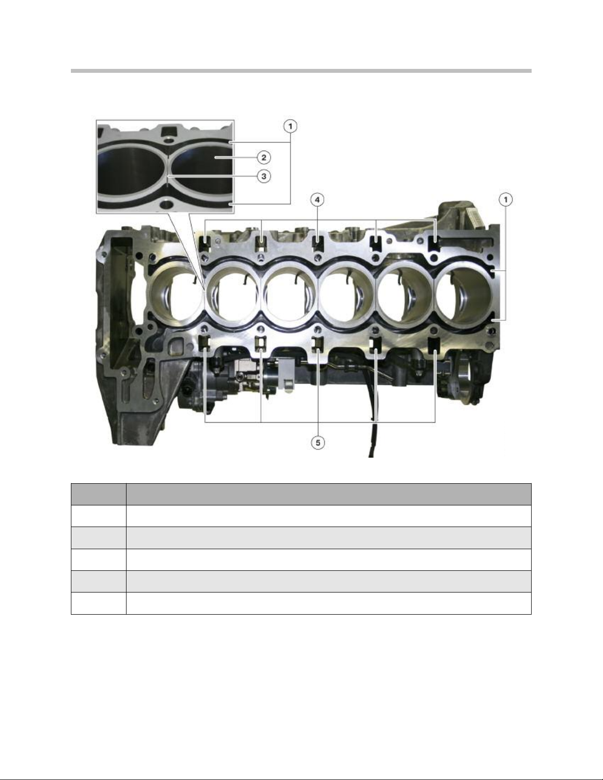
N55, crankcase with web cooling
Index Explanation
1
2
3
4
Oil return ducts, exhaust side
5
Cooling duct
Cylinder liner
Grooved cooling passage
Oil return ducts, intake side
15
N55 Engine
The crankcase has large longitudinal ventilation holes bored between the lower chambers
of the cylinders. The longitudinal ventilation holes improve the pressure equalization,
between the oscillating air columns that are created in the crankcase, by the up and down
movement of the pistons.
This enhances power by relieving the unwanted pressure that acts against the downward
movement of the pistons. It also enhances crankcase ventilation and adds to oil service
life by promoting the movement of blow-by gasses within the engine.
N55, ventilation holes in crankcase
16
N55 Engine
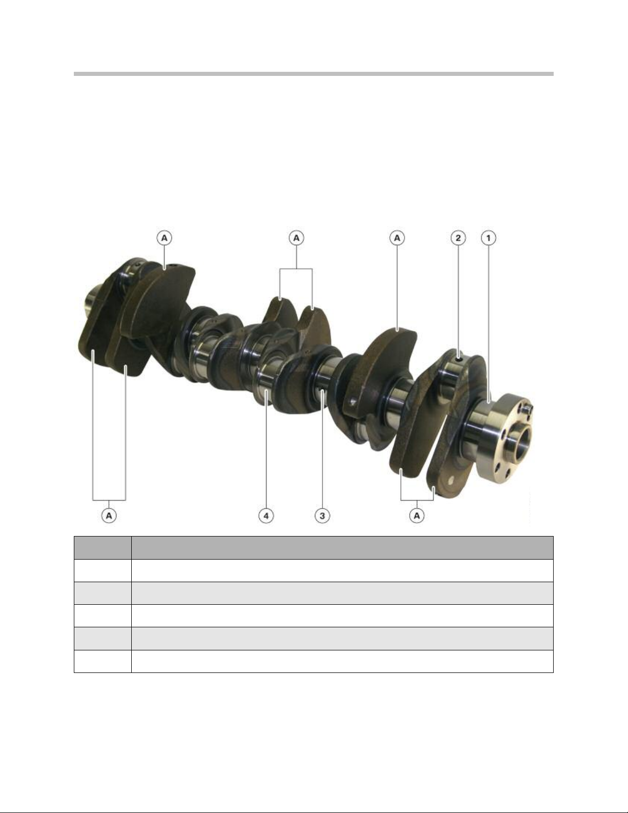
Crankshaft
The crankshaft of the N55 is of lightweight design, at 20.3 kg it’s approximately 3 kg
lighter than the crankshaft in the N54 engine.
The crankshaft is made from cast iron (GGG70). The counterweights are arranged asymmetrically. There is no incremental wheel installed on the crankshaft. The timing chains
are mounted by means of an M18 central bolt.
N55 Crankshaft
Index Explanation
A
1
2
3
4
Oil hole from big-end bearing to main bearing
Oil hole from main bearing to big-end bearing
Big-end bearing journal, cylinder 4
Counterweights
Main bearing journal 7
Crankshaft Main Bearings
As on the N54 engine, the main bearings on the crankshaft are designed as two
component bearings free of lead. The thrust bearing is mounted at the fourth bearing
position.
N55 Engine
17
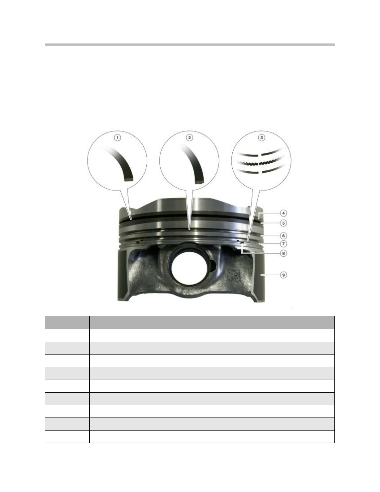
Pistons and Rings
A full slipper skirt type piston with a diameter of 82.5 mm is used. The first piston ring is a
plain rectangular compression ring with a chrome-ceramic coating on the contact surface.
The second piston ring is a tapered faced Napier type ring. The oil scrape ring is
designed as a steel band ring with spring that is also known as VF system.
N55 piston with piston rings
Index Explanation
1
2
3
4
5
6
7
8
9
Plain rectangular compression ring
Ta p er e d faced Napier ring
VF system ring
Steel inlay for first piston ring
Groove for first piston ring
Groove for second piston ring
Groove for oil scraper ring
Hole for lubricating oil drain
Graphite coating
18
N55 Engine
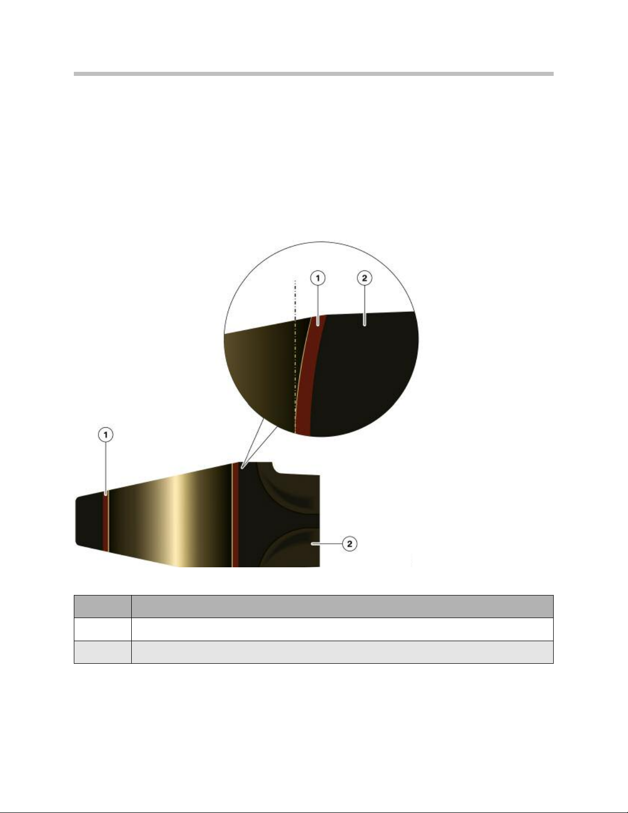
Connecting Rod and Bearings
The size of the connecting rod of the N55 engine is 144.35 mm. A new feature is the
specially formed hole in the small end of the connecting rod. This formed hole is
machined wider on the lower edges of the wrist pin bushing/bore. This design evenly
distributes the force acting on the wrist pin over the entire surface of the rod bushing and
reduces the load at the edges, as the piston is forced downward on the power stroke.
N55, small end of the connecting rod
Index Explanation
1
2
Bushing
Connecting rod
19
N55 Engine
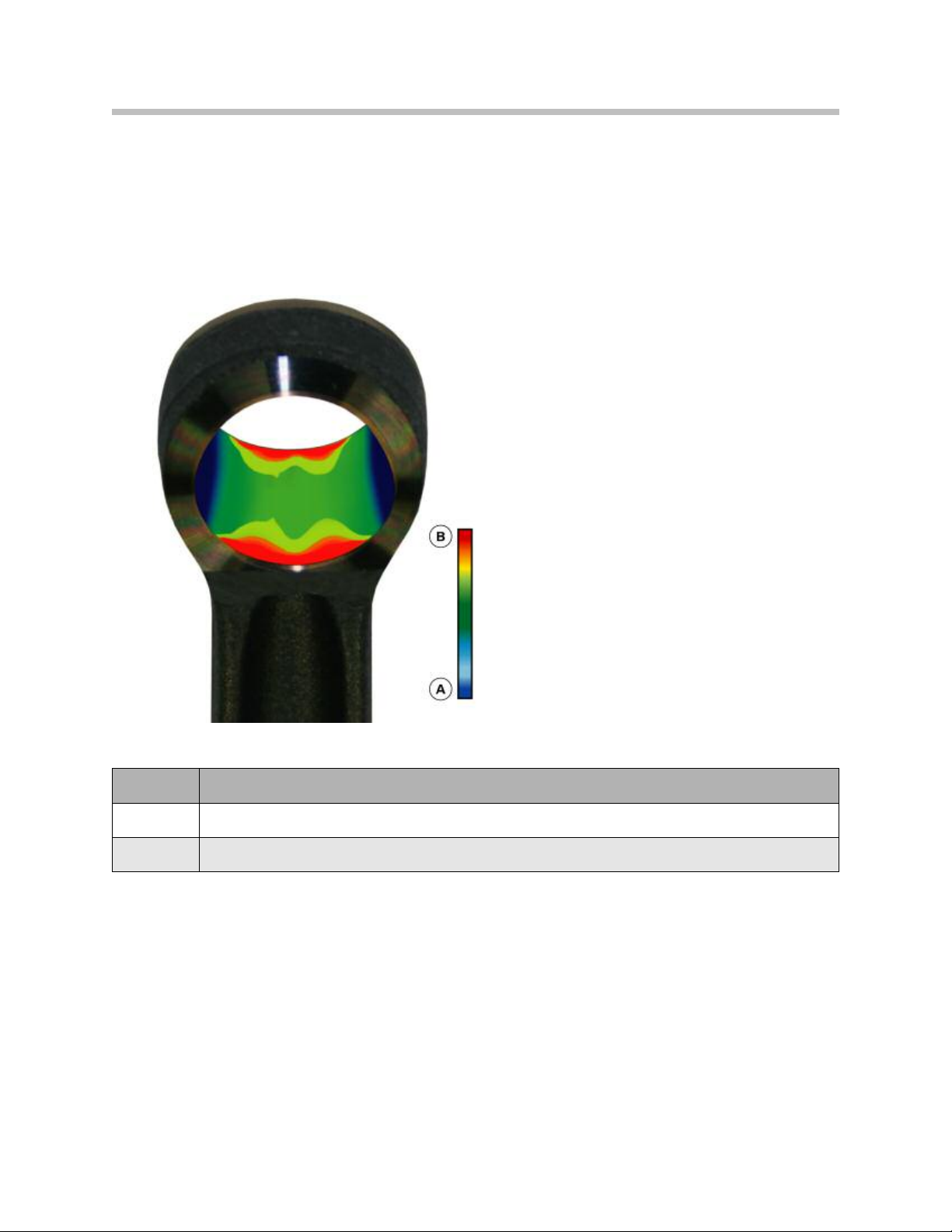
The following graphic shows the surface load on a standard connecting rod without the
formed hole. Due to combustion pressure, the force exerted by the piston via the wrist
pin is mainly transmitted to the edges of the rod bushing.
N54, connecting rod small end without formed hole
Index Explanation
A
B
Low surface load
High surface load
20
N55 Engine
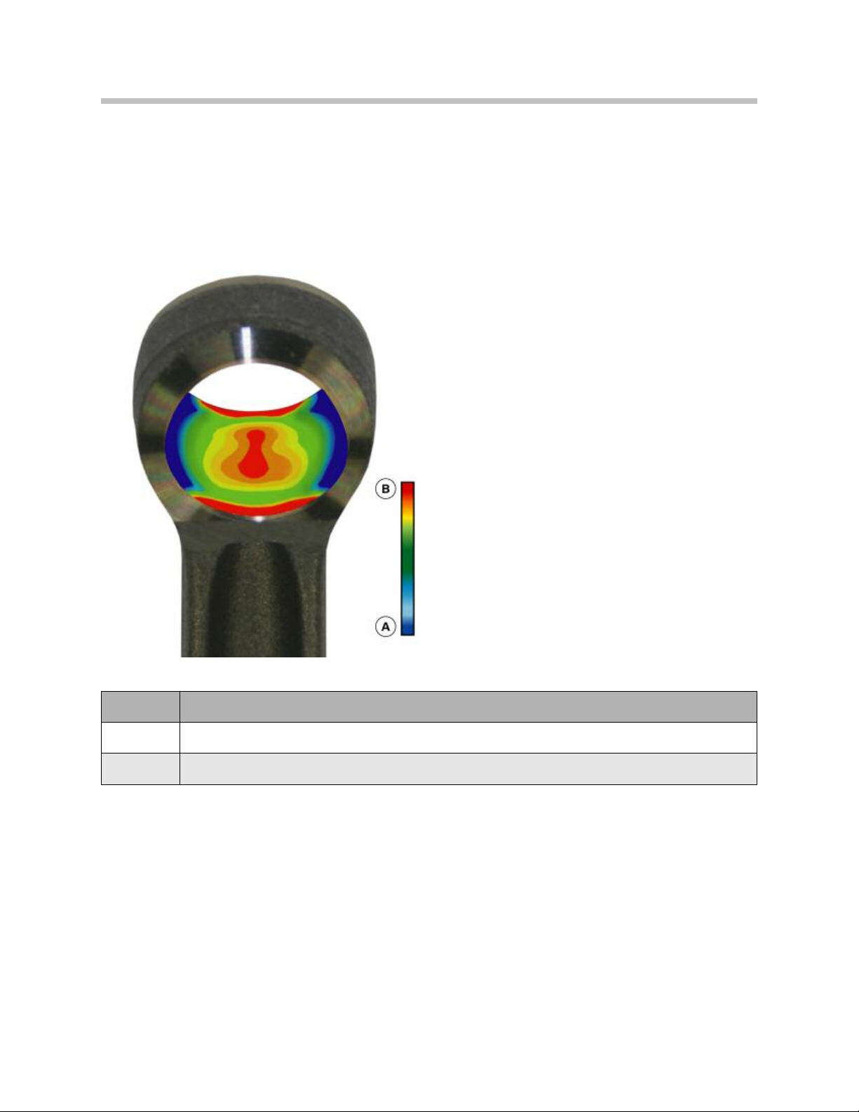
The graphic below illustrates the small end of the connecting rod with a formed hole. The
force is more evenly distributed over a larger area and the load on the edges of the rod
bushing is reduced considerably.
N55, connecting rod small with formed hole
Index Explanation
A
B
Low surface load
High surface load
Lead-free bearing shells are used on the large connecting rod end. The material G-488 is
used on the connecting rod side and the material G-444 on the bearing cap side.
The size M9 x 47 connecting rod bolts are the same on the N55 and N54 connecting
rod.
21
N55 Engine
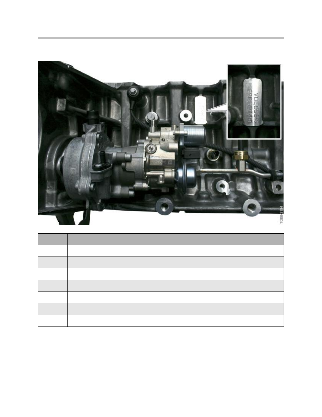
Oil Pan
The oil pan is made from an aluminum casting. The oil deflector and the intake pipe to
the oil pump are designed as one component. To facilitate attachment to the bedplate,
the oil return ducts are designed so that they extend over the oil deflector. Consequently,
the oil return ducts end in the oil sump.
Ducts are provided for the oil supply to the vacuum pump as it is now lubricated by
filtered oil and not by unfiltered oil as on the N54 engine.
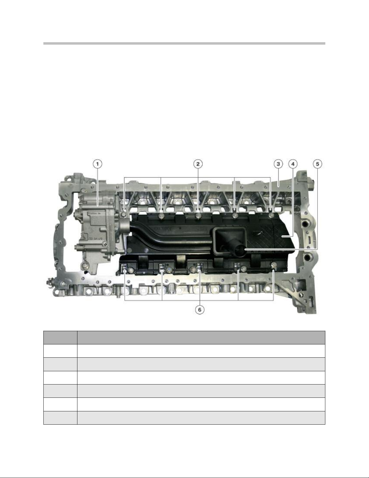
N55, bedplate with oil pump and oil deflector
Index Explanation
1
2
3
4
5
6
Oil return ducts, intake side
Intake manifold with oil screen filter
Oil return ducts, exhaust side
Oil pump
Bedplate
Oil deflector
22
N55 Engine
Electrionic Volume-controlled Oil Pump
A modified version of the volume control oil pump of the N54 engine is used. For the first
time a Duroplast reciprocating slide valve is installed. The volumetric flow control system
operating principle of the oil pump is described in the E71 X6 training material under the
”N63 Engine” available on TIS and ICP.
This type of pump delivers only as much oil as is necessary under the respective engine
operating conditions. No surplus quantities of oil are delivered in low-load operating
ranges. This operating mode reduces the pump work and therefore the fuel consumption
of the engine while also slowing down the oil aging process. The pump is designed as a
slide valve-type vane pump. In delivery mode, the pump shaft is positioned off-center in
the housing and the vanes are displaced radially during rotation. As a result, the vanes
form chambers of differing volume. The oil is drawn in as the volume increases and
expelled into the oil galleries as the volume decreases.
The oil pressure in the system (downstream of the oil filter) acts on the slide against the
force of a compression springs in the control oil chamber. The slide element rotates
about a pivot axis.
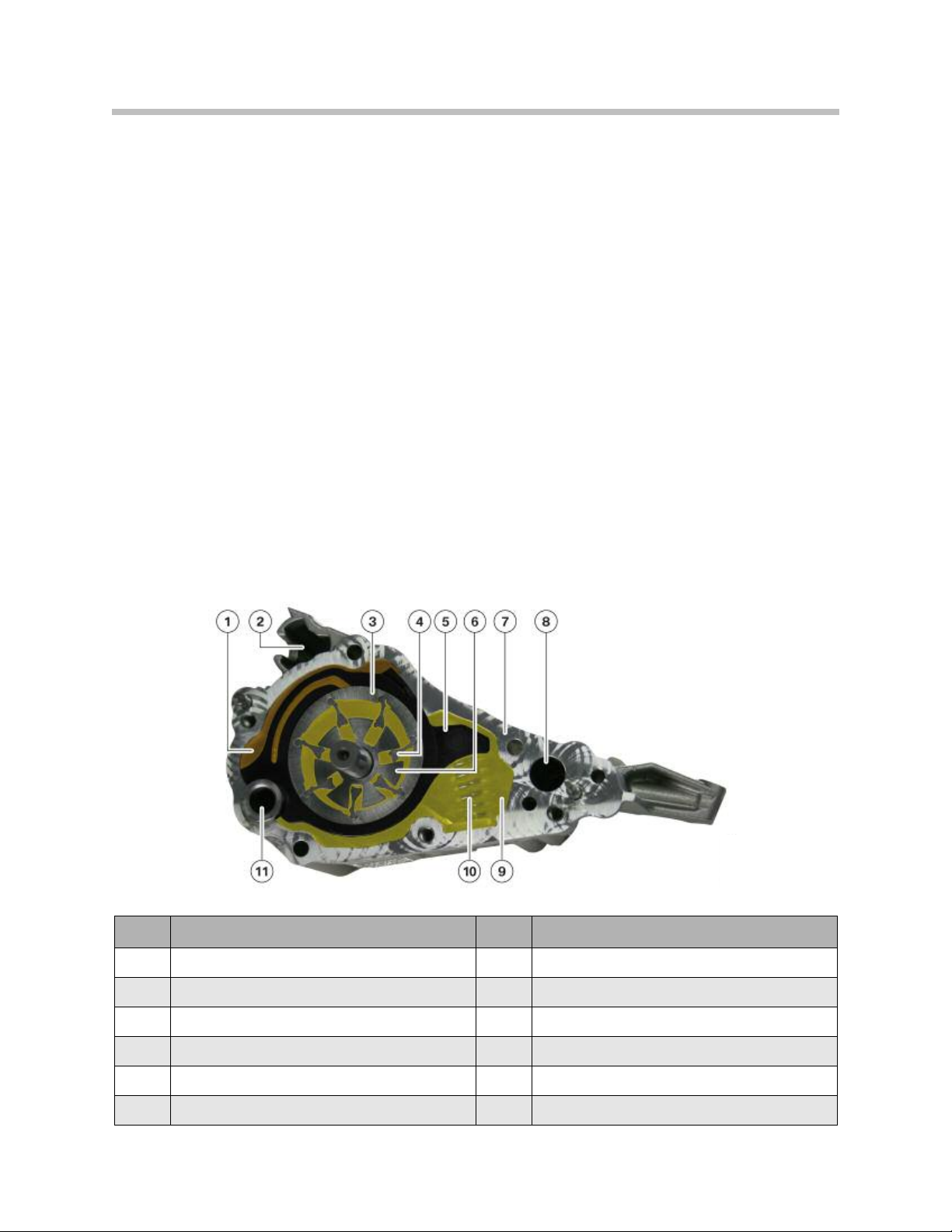
N55, oil pump
Index Explanation Index Explanation
1
2
3
4
5
6
Control oil chamber
Pressure limiting valve
Rotor
Van e
Duroplast slide valve
Inner rotor
7
8
9
10
11
Hole for pressure control valve
Compression spring (2x)
Housing
Damping oil chamber
Pivot axis of rotation
23
N55 Engine

Oil Pump and Pressure Control
The oil pump has been redesigned with regard to the functionality and durability of the
Duroplast reciprocating slide valve. The oil pump used in the N55 engine is a further
development of the shuttle slide valve volume control oil pump. The activation of the oil
pump is adapted by the engine management and controlled through an oil pressure
control valve.
The delivered oil volume is controlled by means of the oil pressure, based on specific
requirements. The modifications, compared to previous pumps, are primarily in the pump
activation system. The oil pressure no longer acts directly on the control piston but rather
directly on the slide valve. The engine management activates the electrohydraulic
pressure control valve, which affects the oil pressure at the slide valve control mechanism
within the oil pump, altering the pump output. This has the advantage of avoiding power
losses by running the oil pump only when needed.
The electrohydraulic pressure control valve controls the pump output and is bolted to the
front of the engine block. It is operated based on a characteristic map within the DME
(ECM) which in turn is based on feedback from the oil pressure sensor. The N55 uses a
special oil pressure sensor for this purpose which functions in the similar way as the HPI
fuel pressure sensor.
Characteristic map-controlled oil pressure
Index Explanation Index Explanation
A
B
1
2
Oil pressure control, hydraulic/ mechanical
Oil pressure (bar)
Engine speed (rpm)
Characteristic map-controlled
oil pressure, full load
3
4
5
Characteristic map-controlled
oil pressure, no load
Saving potential, full load
Saving potential, no load
24
N55 Engine
The oil pressure generated by the oil pump (2) is delivered to the engine’s lubricating
points and hydraulic actuators. This system uses oil pressure feed back to control the
desired operating oil pressure. For this purpose, the oil pressure downstream of the oil
filter (7) and engine oil-to-coolant heat exchanger (9) is adjusted by the DME (map-controlled) via the pressure control valve (4) to the pressure control valve (3).
The actual generated oil pressure is registered by the oil pressure sensor (10) and
recognized by the engine management.
In the event of an electrical malfunction, the oil pressure is set to the default control
setting. The pump compression springs are allowed to expand, moving the slide valve to
its maximum oil pressure position.
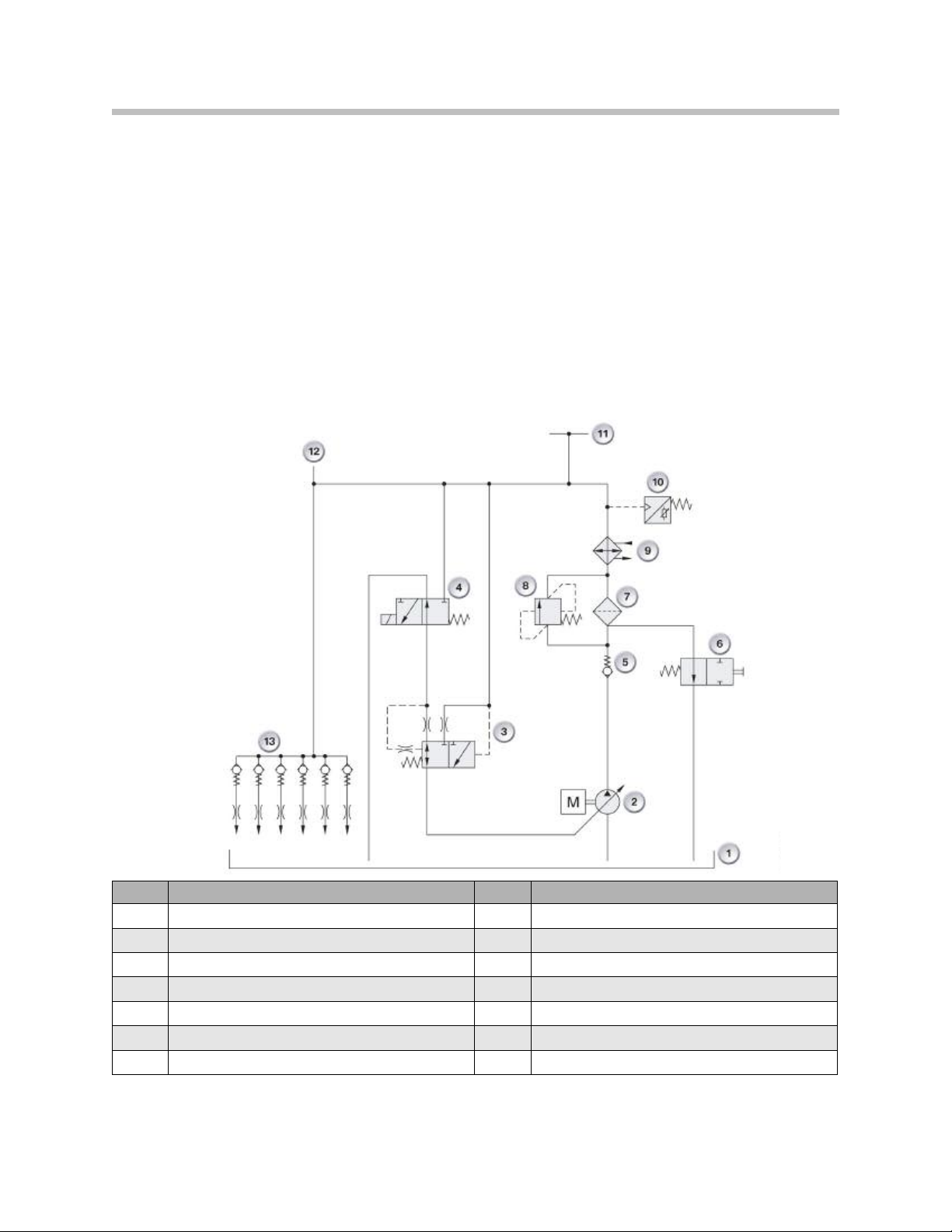
Hydraulic diagram of the N53 engine oil circuit with electronic pressure control
Index Explanation Index Explanation
1
2
3
4
5
6
7
Vol ume controlled oil pump
Pressure regulating valve
Electro-hydraulic pressure regulating valve
Outlet valve at the filter
Oil Pan
Non-return valve
Oil filter
8
9
10
11
12
13
Engine oil to coolant heat exchanger
Filter By-pass valve
Oil Pressure sensor
Lubricating points, cylinder head
Lubricating points, engine block
Oil spray nozzles, piston crowns
Note: The N53 hydraulic circuit diagram shown is for explanation of the oil
pressure control only, and does not apply directly to the N55 engine.
25
N55 Engine
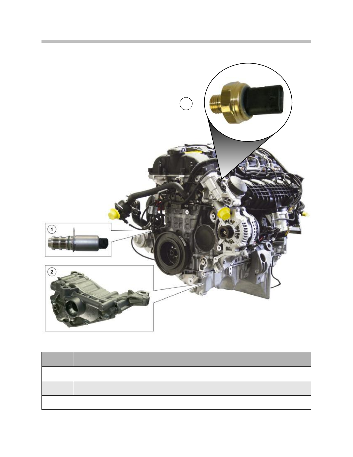
N55, oil pump and pressure control valve
3
Index Explanation
1
2
3
Oil pressure control valve
Oil pump
Oil pressure sensor
26
N55 Engine
Oil Supply
The following graphics show an overview of the oil circuit of the N55. Compared to the
N54 engine, there are considerably fewer oil ducts in the cylinder head. This is mainly due
to the use of the new VANOS solenoid valves.
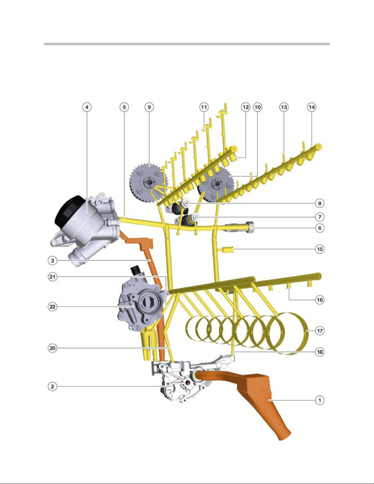
N55, oil passages rear view
27
N55 Engine

Index Explanation
1
2
3
4
5
6
7
8
9
10
11
Intake pipe
Oil pump
Unfiltered oil duct
Oil filter
Main oil duct (filtered oil duct)
Chain tensioner
VAN OS solenoid valve, exhaust side
VAN OS solenoid valve, intake side
VAN OS adjustment unit, intake side
VAN OS adjustment unit, exhaust side
Oil duct for intake camshaft and eccentric shaft lubrication
12
13
14
15
16
17
18
20
21
22
Hydraulic valve lash adjustment
Oil duct for exhaust camshaft lubrication
Hydraulic valve lash adjustment
Connection to exhaust turbocharger lubrication
Connection for oil spray nozzles
Crankshaft bearing
Oil duct for oil pressure control
Oil duct for oil pressure control
Oil duct for vacuum pump lubrication
Vac uum pump
28
N55 Engine
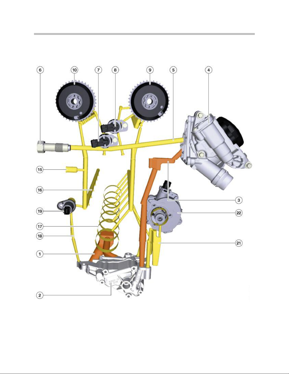
N55, oil passages front view
29
N55 Engine

Index Explanation
1
2
3
4
5
6
7
8
9
10
Intake pipe
Oil pump
Unfiltered oil duct
Oil filter
Main oil duct (filtered oil duct)
Chain tensioner
VAN OS solenoid valve, exhaust side
VAN OS solenoid valve, intake side
VAN OS adjustment unit, intake side
VAN OS adjustment unit, exhaust side
15
16
17
18
19
21
22
Connection to exhaust turbocharger lubrication
Connection for oil spray nozzles
Crankshaft bearing
Oil duct for oil pressure control
Oil pressure control valve
Oil duct for vacuum pump lubrication
Vac uum pump
Oil Filtration and Oil Cooling
The oil filter housing is made from Duroplast. Based on the application, two types of
engine oil coolers may be used. Depending on the oil temperature, a thermostat on the
oil filter housing controls the oil flow through the oil cooler.
30
N55 Engine
 Loading...