

Product Information.
N47 engine.
BMW Service

The information contained in the Product Information and the Workbook form an integral part of
the training literature of Aftersales Training.
Refer to the latest relevant BMW Service information for any changes/supplements to the
technical data.
Information status: November 2006
Contact: conceptinfo@bmw.de
© 2006 BMW AG
München, Germany
Reprints of this publication or its parts require the written approval of
BMW AG, München
VS-12 Aftersales Training

Product Information.
N47 engine.
Rear chain drive
Vacuum pump in the oil sump
Balancing shafts in the crankcase

Notes on this Product Information
Symbols used
The following symbols are used in this Product Information to improve
understanding and to highlight important information:
3 contains information to improve understanding of the systems
described and their function.
1 identifies the end of a note.
Information status and national variants
BMW vehicles satisfy the highest requirements of safety and quality.
Changes in terms of environmental protection, customer benefits and
design render necessary continuous development of systems and
components. Discrepancies may therefore arise between specific details
provided in this Product Information and the vehicles available during the
training course.
This documentation only describes European left-hand-drive variants. In
right-hand-drive vehicles some control elements and components are
arranged differently from what is shown in the graphics in this Product
Information. Further discrepancies may arise from market- or countryspecific equipment specifications.
Additional sources of information
Further information on the individual subjects can be found in the
following:
- in the Owner's Handbook
- in the BMW diagnosis system
- in the Workshop Systems documentation
- in BMW Service Technik.

Contents.
N47 engine.
Objectives
Product Information and reference material for
practical applications
Models 3
Engine variants 3
Introduction 5
System overview 9
Engine identification 9
System components 11
1
1
Overview of engine mechanicals 11
Crankcase 18
Cylinder head and cover 24
Sump 30
Crankcase breather system 31
Crankshaft and bearings 37
Connecting rods and bearings 42
Pistons, piston rings and gudgeon 47
Balancing shafts 54
Rotational vibration damping 57
Camshaft drive system (timing gear) 61
Belt drive and auxiliary equipment 64
Camshafts 67
Lever tappets 72
Hydraulic valve clearance adjustment 74
Valves, valve guides and valve springs 76
Overview of the oil supply 80
From the sump to the oil filter 82
Oil filtration and oil cooling 87
Oil spray nozzles and piston cooling valve 90
Oil monitoring 92

Overview of the intake and exhaust system 106
Intake system 108
Exhaust system 111
Negative pressure system 118
Fuel system 121
Overview of the cooling system 129
Components in the coolant circuit 132
Cooling module 142
Overview of the engine electrical system 143
Functions of the engine electrical system 145
Sensors and actuators 155
Service information 185
System components 185
Test questions 189
Questions 189
Answers to the questions 191

3
Objectives.
N47 engine.
Product Information and reference material for practical applications
This Product Information is intended to
provide you with information on the design
and operation of the N47 engine.
The Product Informationis designed as awork
of reference and supplements the contents of
the BMW Aftersales Training course. The
Product Information is also suitable for private
study.
As preparation for the technical training
course, this Product Information provides an
insight into the new N47 4-cylinder diesel
engine. In conjunction with the practical
exercises carried outin the training course,the
aim of the Product Information is to equip
participants with the skills to carry out
servicing work on the N47 engine.
Existing technical and practical knowledge of
current BMW dieselengineswill make iteasier
to understand the systems and their functions
presented here.
Please remember to work through
the SIP on this topic.
Basic knowledge provides surety in
theory and practice.
1

3
2

4
Models.
N47 engine.
Engine variants
Models with N47 engine for market launch in
March 2007.
3
Model
118d E81 N47D20U0 1995 90/84
120d E81 N47D20O0 1995 90/84
118d E87 N47D20U0 1995 90/84
120d E87 N47D20O0 1995 90/84
320d E92 N47D20O0 1995 90/84
Model series
Engine
Cylinder capacity in cm
Bore/stroke
in mm
Power in
kW/bhp at rpm
105/143
4000
130/177
4000
105/143
4000
130/177
4000
130/177
4000
Torque in
Nm at rpm
300
1750
350
1750
300
1750
350
1750
350
1750
3

4
History
Four-cylinder diesel engines at BMW.
3
Engine
M41D17 318tds E36 1665 66/90 190 DDE2.1 9/94 9/00
M47D20O0 320d E46 1951 100/136 280 DDE3.0 4/98 9/01
M47D20O0 520d E39 1951 100/136 280 DDE3.0 9/99 5/03
M47D20U0 318d E46 1951 85/115 240 DDE3.0 9/01 3/03
M47D20O1 320d E46 1995 110/150 330 DDE5.0 9/01 3/04
M47D20U1 318d E46 1995 85/115 240 DDE5.0 3/03 3/04
M47D20U1 318d E46 1995 85/115 240 DDE506 3/04 3/05
M47D20O1 320d E46 1995 110/150 330 DDE506 3/04 9/06
M47D20U2 118d E87 1995 90/122 280 DDE603 9/04 3/07
M47D20O2 120d E87 1995 120/163 340 DDE604 9/04 3/07
M47D20O2 X3 2.0d E83 1995 110/150 330 DDE506 9/04 9/05
M47D20O2 320d E90 1995 120/163 340 DDE604 3/05 Still
M47D20U2 318d E90 1995 90/122 280 DDE603 9/05 Still
M47D20O2 320d E91 1995 120/163 340 DDE604 9/05 Still
M47D20O2 X3 2.0d E83 1995 110/150 330 DDE604 9/05 Still
Model
Model series
Cylinder
capacity in cm
Power
in kW/bhp
Torque
in Nm
Engine
management
First used
current
current
current
current
Last used
4

Introduction.
N47 engine.
The new generation
5
After eight years, a successful model - yet to
be equalled - is to be replaced. The M47
engine gave the diesel engine at BMW a
respectable pedigree. Offering sporty
acceleration and mighty power coupled with
such low fuel consumption, it soon became
one of the most favourite engines in the BMW
repertoire.
To carry on the baton is the challenge that
faces the successor model, the N47 engine.
Indeed, it is a challenge that it will gladly take
on. With even more power and torque
combined with low fuel consumption and
weight, it is ideally equipped to carry on the
success.
The N47 engine is a completely new
development bestowed with a multitude of
new applications. This has been combined
with the latestdieseltechnology and a number
of tried-and-tested solutions.
An overview of innovations, modifications and special features
Debuting on BMW diesel engines
• Chain driveand high-pressure pump on the
force transmitting side (rear)
• Balancing shafts integrated in the
crankcase with needle bearings
• Common oil/vacuum pump in the oil sump
• Double-sided belt drive
• All auxiliaryequipment on the left-hand side
of the engine
• Rotational vibration damper with freewheel
• Exhaust gas recirculation cooler with
bypass (only upper powerclasswithmanual
transmission)
• Starter on the right-hand side of the engine
• New CP4.1 single-piston high-pressure
pump with 1,800 bar maximum pressure
(lower power class: 1,600 bar)
• Majority of oil ducts cast using a new
casting method
• DDE7 engine management
• Active crankshaft sensor with reverse
rotation detection
• Ceramic glow plugs.
Modifications by comparison with the
predecessor
• Aluminium crankcase with thermally-joined,
grey cast-iron cylinder bushes
• PIEZO injectors (upper power class only)
• More compact roller cam followers
• Two-piece cylinder head
• Reinforcement shell for the crankcase
• Pressure-controlled electric fuel pump
• Fuel filter heating controlled by the DDE
• Crankshaft main bearing caps with indent fit
• Electronic oil level measurement with QLT.
Other key data
• Oil separation in the cylinder head cover
with cyclone filters
• Composite camshafts built in accordance
with the Presta method
• Electric swirl flaps (upper power class only)
• Exhaust turbocharger with electrically
variable turbine geometry (VNT)
• Oxi-cat and DPF in a common, engine-side
housing.
5

5
Technical data
Designation M47D20U2 N47D20U0 M47D20O2 N47D20O0
Engine type 4 inline 4 inline 4 inline 4 inline
Cylinder capacity [cm3] 1,995 1,995 1,995 1,995
Stroke/bore [mm] 90/84 90/84 90/84 90/84
Output
at engine speed
Torque (1st gear)
at engine speed
Torque (remaining)
at engine speed
Cutoff speed [rpm] 4,600 4,600 4,600 4,600
Power output per litre [kW/l] 45.11 52.63 60.15 65.16
Compression ratio ε 17.0 16.0 17.0 16.0
Cylinder gap [mm] 91 91 91 91
Valves/cylinders 4 4 4 4
Inlet valve dia. [mm] 25.9 27.2 25.9 27.2
Exhaust valve dia. [mm] 25.9 24.6 25.9 24.6
Main bearing journal
dia. of crankshaft
Big-end bearing journal
dia. of crankshaft
Engine management DDE603 DDE7.0 DDE604 DDE7.1
Emissions standard EURO 4 EURO 4 EURO 4 EURO 4
[kW/
bhp]
[rpm]
[Nm]
[rpm]
[Nm]
[rpm]
[mm] 60 55 60 55
[mm] 45 50 45 50
90/122
4,000
240
1,750
280
1,750
105/143
4,000
240
1,750
300
1,750
120/163
4,000
280
2,000
340
2,000
130/177
4,000
280
1,750
350
1,750
6

Full-load diagram
The N47 engine is set apart from its
predecessor by an increase in overall
performance and a beefier torque curve.
5
1 - Full load diagram of the N47D20U0 by comparison with its
predecessor
2 - Full load diagram of the N47D20U0 by comparison with its
predecessor
7

5
8

6
System overview.
N47 engine.
Engine identification
Engine designation
The engine designation is used in the
technical documentation for unique
identification of the engine.
The N47 engine has the following variants:
• N47D20U0
• N47D20O0
The technical documentation may also
contain the abbreviated form of the engine
designation, N47, which only makes it
possible to identify the engine model.
This means:
Index Explanation
N BMW Group "New generation"
4 4-cylinder engine
7 Direct diesel injection
D Diesel engine
20 2.0-litre capacity
U/O Lower/upper power class
0 New development
Engine identifier and number
The crankcase ofthe engine ismarked with an
identifier for unique identification and
assignment of the engine. This engine
identifier is also required for approval by the
authorities. The first seven positions are
relevant here.
With the N47 engine, the engine identifier is
now a diesel engine identifier that has been
changed so as to comply with the new
standard wherebythe first sixpositions are the
same as the engine designation.
The engine number is a serial number that
makes it possible to uniquely identify any
individual engine.
The engine identifier and number are located
on the crankcase on the bracket of the highpressure fuel pump.
1 - Engine identifier and number on the N47 engine
9

6
10

7
System components.
N47 engine.
Overview of engine mechanicals
The engine mechanicals can be subdivided
into three major systems:
• Engine casing
• Crankshaft drive system
• Valvegear
Those threesystems are in a stateof constant
interaction with one another. This interaction
has a very significant influence on engine
properties.
Some important interrelationships, such as
firing interval and firing order, will now be
explained in more detail.
Interrelationships
The following table shows the key data for the
N47 inrespect of firing interval and firing order.
N47 engine
Engine configuration/no. of cylinders 4-cylinder in-line engine
Crankshaft crank-pin offset 180°
Firing interval 180° CR
Firing order 1-3-4-2
Firing interval
The firing interval is the angle of crankshaft
rotation between two successive ignitions.
In the course of a complete engine operating
cycle, each cylinder ignites once. The fourstroke cycle (intake, compression, power,
exhaust) of an internal combustion engine
takes two complete revolutions of the
crankshaft, i.e. 720° of rotation.
Having the same firing interval between all
ignition points ensures that the engine runs
evenly at all speeds. Such a firing interval is
calculated as follows:
Firing interval = 720° / Number of cylinders
With a 4-cylinder engine like the N47, this
produces a firing interval of 180° crankshaft.
The firing interval is determined by the
crankshaft's crank-pin offset (the angular
separation of the crank arms), i.e. the angle
between the crank pins for successively firing
cylinders (as determined by the firing order).
Firing order
The firing order is the order in which the
cylinders of an engine are ignited.
The firing order is directly responsible for how
smoothly an engine runs. It is determined on
the basis of the engine configuration, number
of cylinders and firing interval.
The firing order is always quoted starting from
cylinder number 1.
With a 4-cylinder in-line engine, a firing order
of 1-3-4-2 hasprovento be themostideal and
this is also used for the N47 engine.
Cylinder numbering order
Even though the N47 engine has the timing
gear at the rear, the numbering order begins
on the opposite side from which force is
transmitted, like in all BMW engines. The first
cylinder is therefore at the front.
11
7
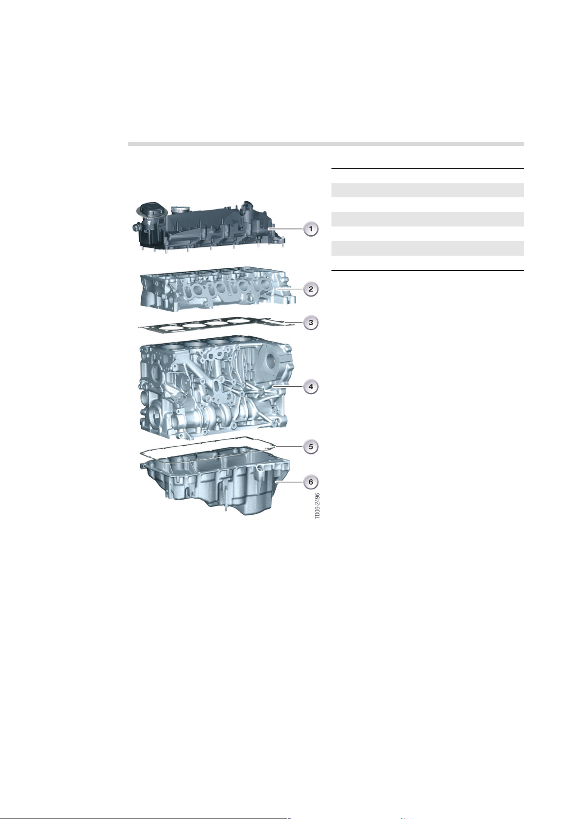
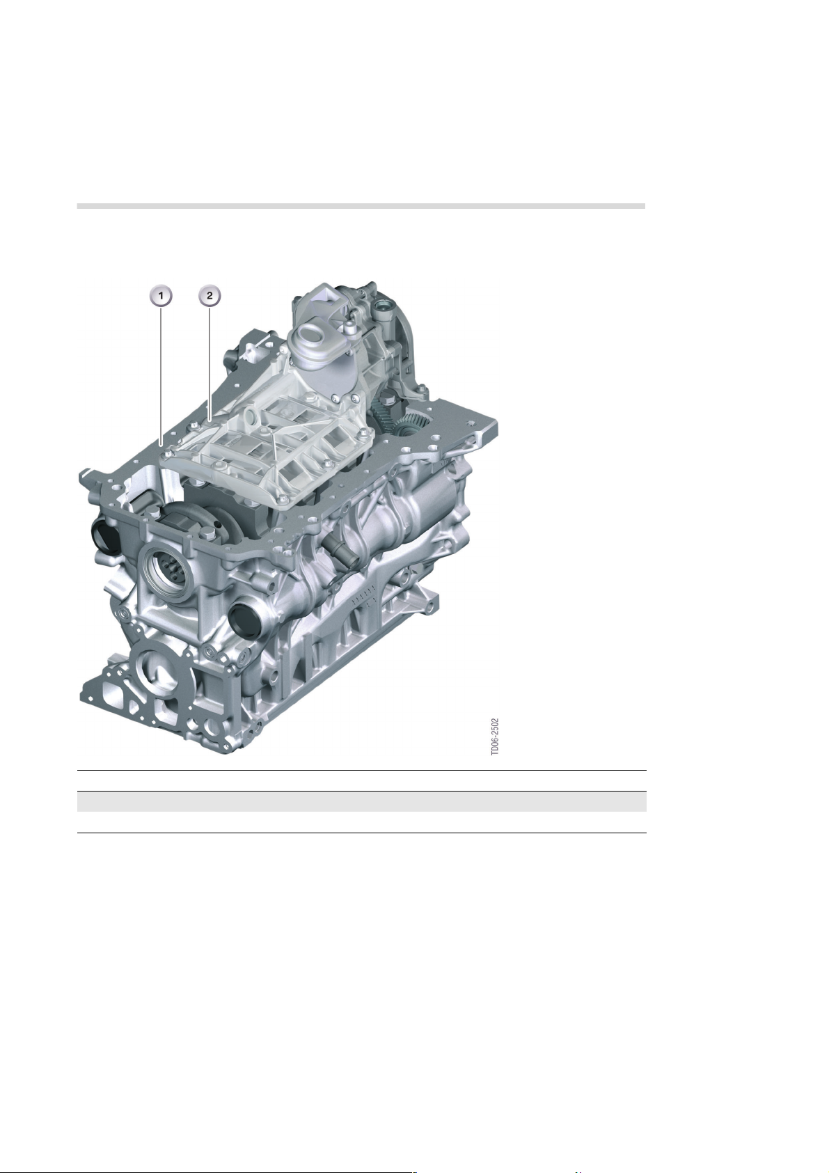
Engine casing
The graphic shows the components of the
engine casing.
Index Explanation
1 Cylinder head cover
2 Cylinder head
3 Cylinder head seal
4 Crankcase
5 Sump gasket
6 Sump
In addition, gaskets and bolts are also part of
this system so that it can perform its job.
That job consists essentially of the following
tasks:
• Containing the forces generated by
operation of the engine
• Sealing functions for the combustion
chamber, engine oil and coolant
• Holding the crankshaft drive system,
valvegear and other components
12
1 - N47 engine casing

7
Crankshaft drive system
The crankshaft drive system, also known as
the power unit, is a function group that
converts the combustion chamber pressure
into kinetic energy. In the process, the
crankshaft converts the linear motion of the
pistons into a rotary motion. The crankshaft
drive systemrepresents the optimumin terms
of work utilization, efficiency and technical
practicability for the task in question.
Index Explanation Index Explanation
1 Connecting rod 3 Crankshaft
2 Piston
Nevertheless, the following technical
limitations and design challenges have to be
dealt with:
• Engine speed limitation due to inertial
forces
• Uneven power delivery over the course of
an operating cycle
• Generation of torsional vibrations that place
stresses on the crankshaft and drive train
• Interaction of the various frictional surfaces
2 - N47 engine crankshaft
drive
13

7
Valvegear
The engine has to be supplied with air in a
regular cycle, while the exhaust gases that it
produces must be expelled. The intake of
fresh air and the ejection of exhaust gas is
referred to as the charge or gas exchange
cycle. Inthe course of the gasexchange cycle,
the inlet and exhaust ducts are periodically
opened and closed by the inlet and exhaust
valves.
The inlet and exhaust valves take the form of
poppet valves. The timing and sequence of
the valve movements are determined by the
camshaft.
The entire mechanism for transferring cam lift
to the valve is known as the valvegear.
In the N47 engine, the crankshaft and
camshaft are mechanically linked by a timing
chain. Timing is therefore fixed.
Design
The valvegear is made up of the following
components:
• Camshafts
• Transmitting elements (roller cam
followers)
• Valves (complete valve assemblies))
• Hydraulic valve clearance adjustment
(HVA).
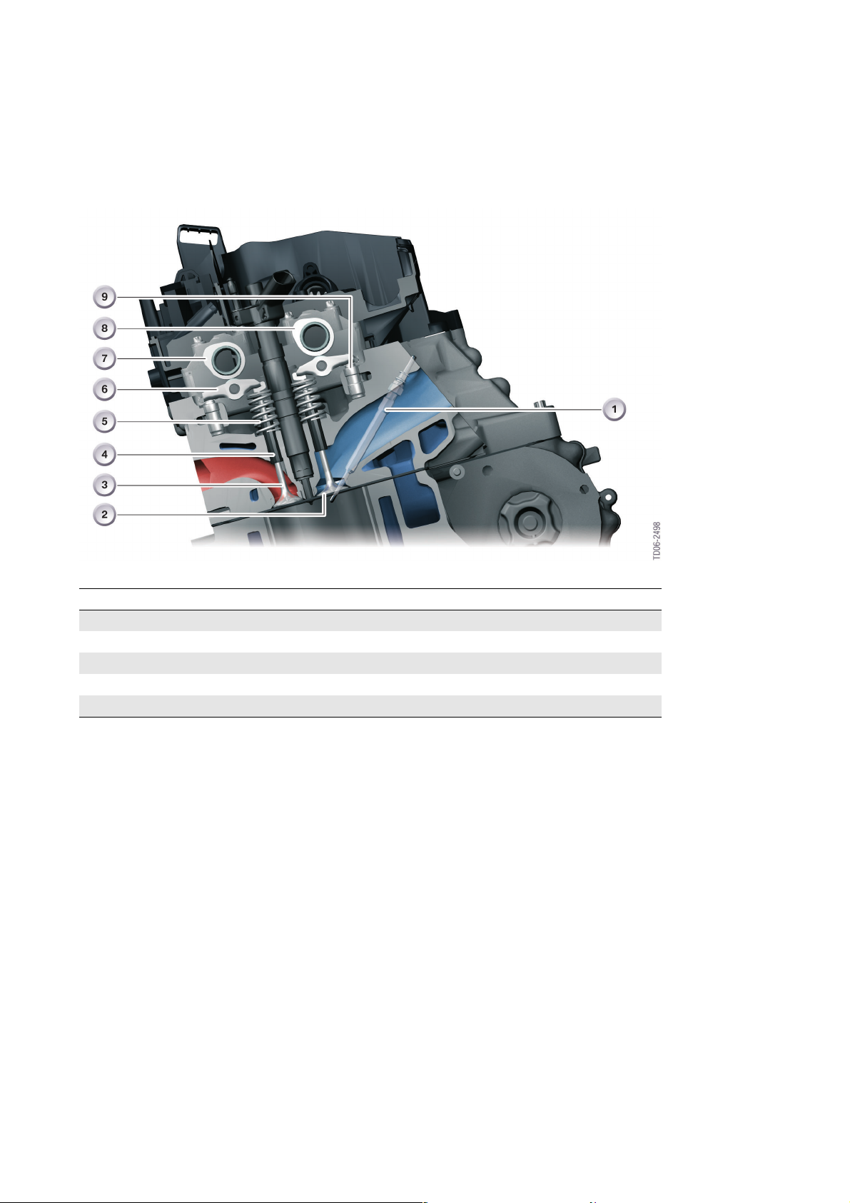
The following graphic shows the design of the
valvegear inthe four-valve cylinderhead of the
N47 engine.
14
7
3 - N47 engine valvegear
Index Explanation Index Explanation
1 Glow plug 6 Roller cam follower
2 Inlet valve 7 Exhaust camshaft
3 Exhaust valve 8 Inlet camshaft
4 Valve guide 9 Hydraulic valve-clearance adjuster
5 Valve spring
Design types
There are a variety of valvegear designs. They
are distinguished according to the following
features:
• Number and position of the valves
• Number and position of the camshafts
• Method of actuation of the valves
• Method of valve clearance adjustment
The designation of the type of valvegear
depends on the first two attributes. The
possible variations are listed below.
Like all current BMW diesel engines, the N47
engine has a DOHC valvegear layout.
This stands for "double overhead camshaft"
and means that the engine has overhead
valves with two camshafts located above the
cylinders. One camshaft is used for the intake
valves, the other for the exhaust valves.
Cam movement on the N47 engine is
transferred from the camshaft to the valve by
roller cam followers in the same way as it is on
all current BMW diesel engines.
The N47 is equipped with valve clearance
adjustment (HVA) to ensure that the correct
amount of playismaintained between the cam
of the camshaft and the roller cam follower.
The following graphic shows the components
of the valvegear on the N47 engine.
15

7
4 - N47 engine valvegear components
Index Explanation Index Explanation
1 Inlet camshaft 7 Valve spring
2 Hydraulic valve-clearance adjuster 8 Lower valve spring retainer
3 Roller cam follower 9 Upper valve spring retainer
4 Valve stem seal 10 Valve guide
5 Valve collets 11 Exhaust valve
6 Inlet valve 12 Exhaust camshaft
Lower valve spring retainer (8) and valve stem
seal (4) form a single component.
16

Timing diagram
7
5 - N47 engine timing diagram
M47TU2
inlet
Valve diameter [mm] 25.9 27.2 25.9 24.6
Max. valve lift [mm] 7.5 7.5 7.5 8.0
Lobe separation [°cranks
haft]
Valve opens [°cranks
haft]
Valve closes [°cranks
haft]
Valve open duration [°cranks
haft]
Inlet valve
The diameter of the inlet valve has been
increased by comparison with the M47TU2.
With no difference in timing, a wider opening
cross section yields improved inflow
characteristics, facilitating the charge cycle.
100 100 108 108
352.0 352.0 142.0 140.7
568.0 568.0 364.0 362.5
216.0 216.0 222.0 221.8
N47
inlet
Exhaust valve
The diameter of the exhaust valve has been
reduced by comparison with the predecessor.
Nevertheless, a greater valve lift produces
better flow characteristicsduringejection.The
opening duration has been marginally
reduced.
M47TU2
exhaust
N47
exhaust
17

7
Crankcase
General information
The crankcase, also known as the cylinder
block or engine block, comprises the
cylinders, the cooling jacket and the
crankshaft housing.
The crankcase of the N47 engine is an entirely
new development.
The special features of the crankcase of the
N47 engine are:
• Crankcase made of aluminium
• Balancing shafts integrated in the
crankcase
• Chain drive located on the force
transmitting side
• Majority of pressurized oil ducts are precast
• Main bearing cap made of sintered metal.
Further technical attributes include:
• Closed-deck design
• Main bearing pedestal with side walls that
extend downwards and individual main
bearing caps
• Main bearing caps with indent fit
• dry, thermally-joined, grey cast-iron cylinder
bushes.
18

7
Design
To provide a better description of the type of
crankcase design, this has been subdivided
into various sections. The types of design can
be classified according to the design of the
following items:
• Deck
• Main bearing pedestals
• Cylinders
Index Explanation Index Explanation
1 Deck 4 Bearing pedestal
2 Crankcase 5 Hole for crankshaft
3 Ventilation window (aperture) 6 Main bearing cap
Deck
The design of the deck affects not only the
choice of casting method but also the rigidity
of the crankcase. A distinction is made
between an open-deck and closed-deck
design.
The N47 engine is equipped with a crankcase
with a closed-deck design.
As the name suggests, a closed deck is, to a
large extent, closed in the area surrounding
the cylinders.
There are holes and openings for oil pressure
and return channels, coolant circulation
channels, crankcase vents and cylinder-head
bolts.
The coolant-channel openings connect the
coolant chamber surrounding the cylinders
with the coolant jacket in the cylinder head.
While this design does have certain
disadvantages in respect of cylinder cooling in
the TDC range, its benefits outweigh those of
the open-deck design what with the greater
rigidity of the deck and thus less deck
deformation, less cylinder twist and better
noise characteristics.
6 - Layout of the N47 engine
crankcase
19
7
Main bearing pedestals
The design of the main bearing pedestal area
is therefore of particular importance because
this is where the forces acting on the
crankshaft bearings are absorbed.
The different types ofdesignaredistinguished
by the partition between the crankcase and
the sump and the design of the main bearing
caps.
In the N47 engine, the partition is below the
centre of the crankshaft; the side walls of the
crankcase extend downwards. Individual main
bearing caps are used.
This design provides high rigidity and is costeffective to manufacture.
Main bearing caps
The main bearing caps form the lower seals
for thebearing pedestals and are rigidlybolted
to them. When the crankcase is
manufactured, the bearingpedestalsand caps
are machinedas one. Therefore, precise fixing
of their relative positions is absolutely
imperative. This is normally done by locating
dowels or cut-away surfaces at the sides of
the bearing pedestals. If the crankcase and
main bearing caps are made of the same
material, the two components may be made
as one and then split by cracking.
In the N47 engine, a relatively new method is
employed to ensure precise positioning. This
involves an indent fit in the contact surface
between the bearing pedestal and the main
bearing cap. This technology was firstused on
the M67TU engine.
This positioning method ensures there is an
absolutely flush surface junction between the
bearing pedestal and main bearing cap in the
bore for the main bearings even after
dismantling and reassembly.
Main bearing caps with an indent fit are
designed with a profile. During the initial
tightening of the main bearing bolts, this
profile is indented into the housing-side
bearing pedestal surface and creates a
positive lock along the transverse and
longitudinal axis of the engine.
Bearing pedestal
The bearing pedestal is the top half of a
crankshaft main bearing in the crankcase.
Bearing pedestals are always integrated into
the cast of the crankcase.
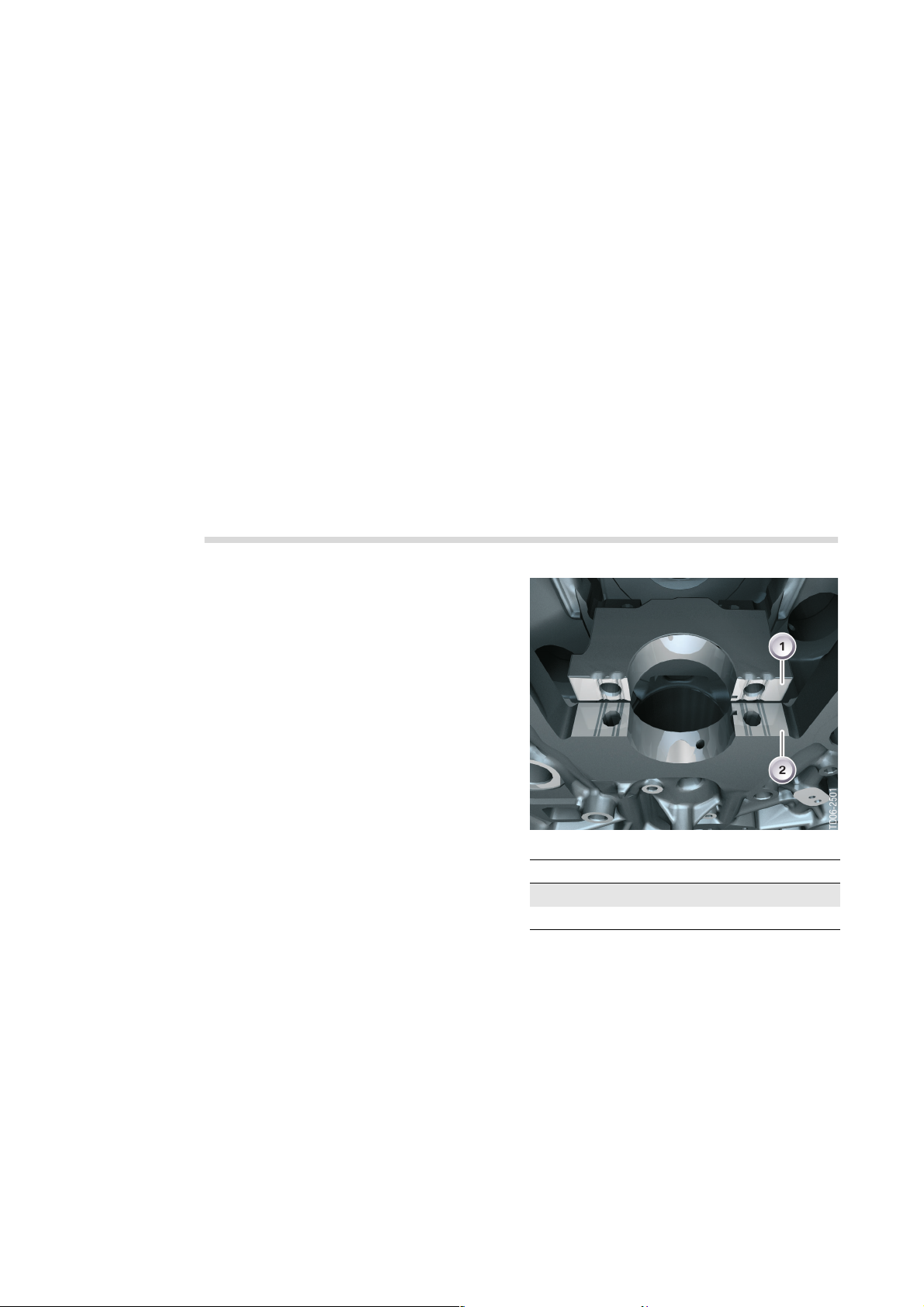
In the N47 engine, there are ventilation
windows in the bearing pedestals above the
crankshaft.
When the engine is running, the air andvapour
inside the crankshaftcavity are continuouslyin
motion. The action of the pistons has a pumplike effect on those gases. The ventilation
windows reduce these losses because they
facilitate pressure compensation in the entire
crankcase.
7 - N47 engine main bearing cap with indent fit
Index Explanation
1 Main bearing cap
2 Main bearing pedestal
To provide positive lock along the longitudinal
axis of the engine, the profile must be shorter
than the housing-side contact surface. In this
way, the profile does not protrude but instead
has a limit position. To avoid making the
bearing pedestal any wider than necessary,
the bearing cap is slightly tapered near the
profile.
Unlike the M67TU, only two rather than six
profile elements per contact surface are used.
The main bearing cap is made of an extremely
rigid, sintered iron material.
20
Reinforcement shell
A reinforcement shell bolted onto the
crankcase from underneath provides the
7
crankcase and crankshaft bearings with
additional reinforcement.
Index Explanation
1 Crankcase
2 Reinforcement shell
The reinforcement shellissimilar in function to
the reinforcement on the M67TU engine; the
only difference is that there are no individual
reinforcement brackets used, but a common
reinforcement shell covering the three centre
crankshaft bearings.
8 - Crankcase with
reinforcement shell in the
N47 engine
This reinforcement shell reinforces the
crankcase itself and additionally forms a
connection to the main bearing caps. To this
end, the reinforcement shell is bolted to the
crankcase and the main bearing caps.
21
7
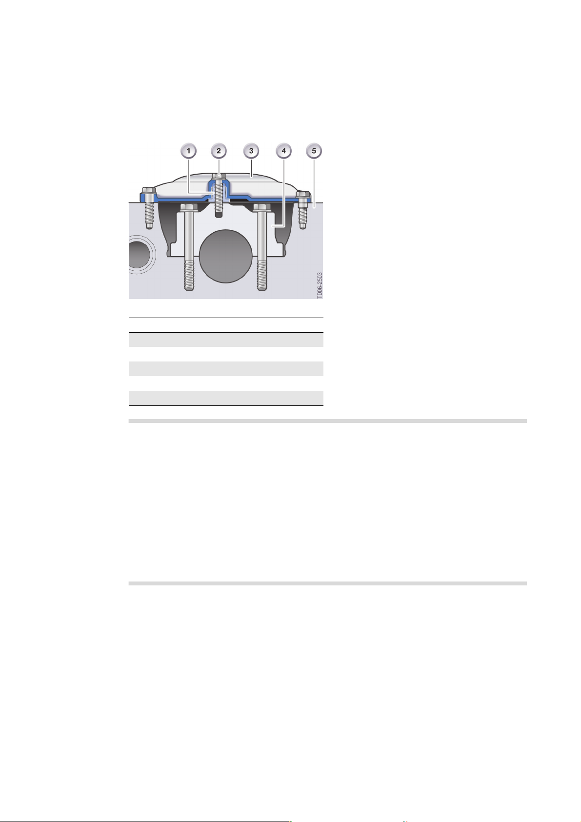
A spacer sleeve is screwed into the
reinforcement shell to exertadefinedpressure
on the main bearing cap. After the
reinforcement shell has been connected to
the crankcase, the spacer sleeve is tightened
to a defined torque against the main bearing
cap. The reinforcement shell is then bolted to
the main bearing cap. This method produces
an extremely rigid system overall.
3 Before the reinforcement shell is fitted, it
is essential that the spacer sleeves be
screwed into the reinforcement shell fully,
otherwise there is a risk of damage. The
procedure in the repair instructions must be
9 - Connection between reinforcement shell and main bearing cap
Index Explanation
1 Spacer sleeve
2 Bolt in the main bearing cap
3 Reinforcement shell
4 Main bearing cap
5 Crankcase
observed. 1
The reinforcement shell has the additional
task of being an oil deflector. It is also
connected to the oil/vacuum pump and
contains the untreated and purified oil ducts.
Cylinder
As part of the combustion chamber, the
cylinder issubjected to high thermal loads and
pressures. With its finely machined surface,
the cylinder liner provides good anti-friction
and sealing characteristics in interaction with
the piston rings. In addition, the cylinder
carries the heat to the crankcase or directly to
the coolant.
Since the aluminium of the crankcase is
unable to meet requirements, the N47 engine
is equipped with cylinder bushes.
Material
The N47 engine has a crankcase made of
aluminium alloy, while the M47 engine has
until recently been manufactured with a grey
cast-iron crankcase. Aluminium crankcases
were introduced on the M67TU and M57TU2
engine.
These are made of grey cast iron and are
thermally joined. Thermally joined means that
the cold cylinder bushes are inserted into the
heated crankcase. As it cools, the crankcase
contracts, therebyensuring firmseating of the
cylinder bushes.
Dry bushes are used in the N47 engine. This
means that the cylinder bush has no direct
contact with thewater jacket. Thewater jacket
is completely enclosed by the crankcase cast.
The crankcase isone of theheaviest individual
components anywhere onthevehicle. It is also
located in a position critical to driving
dynamics, i.e. above the front axle. For this
reason, it makes sense to exploit any potential
for weight reduction to the maximum.
22

7
The density ofaluminiumalloys is about athird
that of grey iron. However, that cannot be
converted one-for-one into a weight
advantage because the lower strength of the
material means the crankcase has to be made
thicker. Nevertheless, its use still sees a
10 - Development of crankcase weight and engine output
Index Explanation Index Explanation
A Weight of the crankcase B Engine output
remarkable advantage in terms of weight.
Indeed, the crankcase of the N47 engine is 38
% lighterthan that ofthe M47TU2 - and thisis
despite the fact that the N47 is able to offer
higher output.
Engine Power
output
M47 100 kW 43 kg
M47TU 110 kW 44 kg
M47TU2 120 kW 45 kg
N47 130 kW 28 kg
Weight of the
crankcase
Other properties of aluminium alloys are:
• good heat conductivity
• good chemical resistance
• positive strength qualities
• good machinability
Pure aluminium is not suitable as a casting
material for crankcases because its strength
properties are inadequate. This is why the
heat-treated alloy AlSi8Cu3, already triedand-tested on many a BMW engine, is used
for the crankcase of the N47 engine.
23

7
Cylinder head and cover
General information
There is hardly an engine assembly more
influential on such operating properties as
output efficiency, fuel consumption, and
torque, exhaust emissions and noise
characteristics than the assembled cylinder
head. The cylinder head accommodates
virtually the entire engine management
system.
The cylinder head of the N47 engine largely
conforms to the standards for current diesel
engines. Aspecial feature, however,is that the
cylinder head comprises two large cast parts.
The camshafts are integrated inside their own
camshaft carrier.
The cylinder head of the N47 engine stands
out for the following technical features:
• Material: AlSI7MgCu0.5
• Two-piece cylinder head with camshaft
carrier
• Crossflow cooling
• Integrated EGR duct
• Four valves per cylinder
• Parallel valve arrangement (axes parallel
with the cylinder axes)
• Tangential duct and swirl duct.
Design
The shaping of the cylinder head is
determined to a very large degree by the
components that it accommodates. The
following factors fundamentally affect the
shape of the cylinder head:
• Number and position of the valves
• Number and position of the camshafts
• Position of the glow plugs
• Position of the injectors and injection
method
• Shape of the inlet and exhaust ducts
One of the requirements of the cylinder head
is that it should be as compact as possible.
Essentially, cylinder heads are classified
according to the following criteria:
• Number of components
• Number of valves
• Cooling method
24
 Loading...