

BMW MINI Wallbox Plus, Wallbox Plus 22kW T2, BMW-10-EC240522-E1R, Wallbox Plus 22kW T2S, BMW-10-ESS40022-E1R Installation Instructions Manual
...Page 1
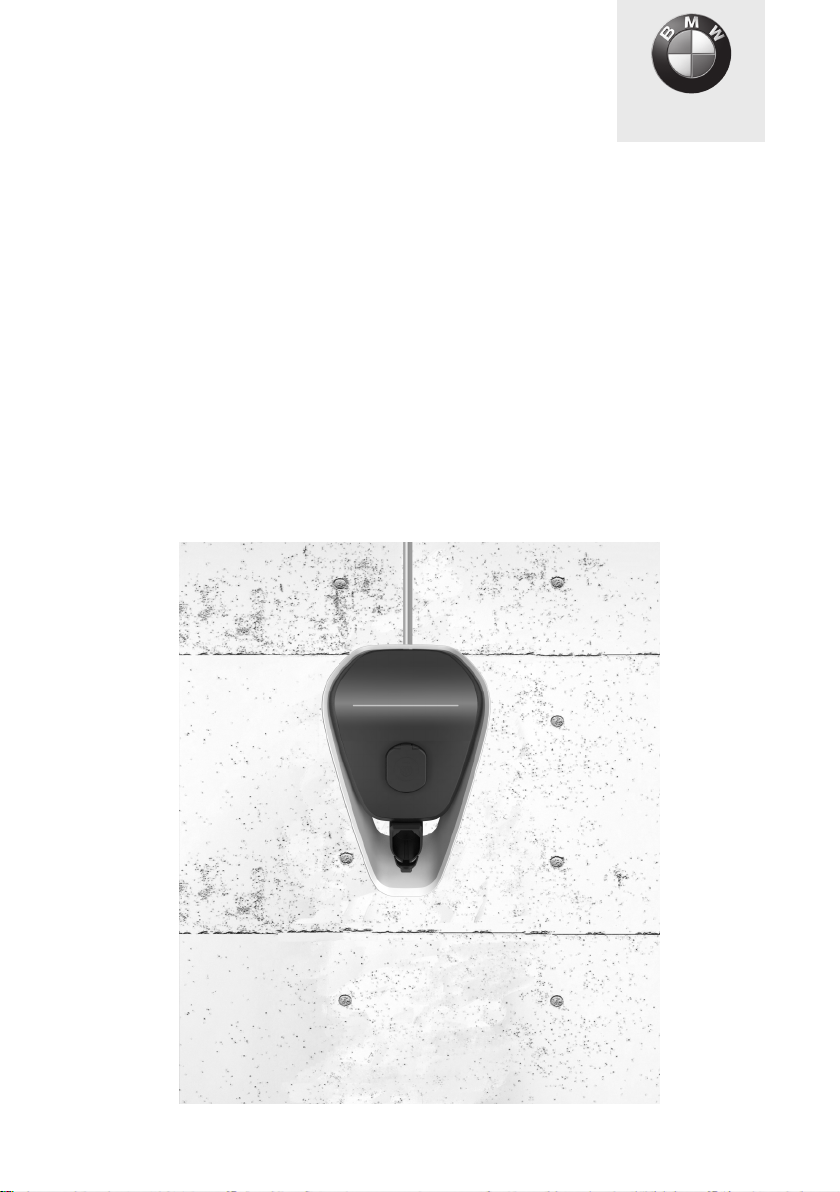
MINI Wallbox Plus
Freude am Fahren
Installation instructions
Page 2

Page 3

MINI Wallbox Plus
Installation instructions
5
EN
Page 4

Page 5

MINI Wallbox Plus
Installation instructions
Contents
INFORMATION 9
Safety information 9
Intended use 11
About this manual 11
Package 12
Warranty 12
OPERATION 13
Displays and controls 13
SPECIFICATIONS 14
General criteria for selecting an installation site 14
Specifications for the electrical connection 15
INTEGRATION OF EXTERNAL METERS 16
Domestic connection monitoring (post-meter fuse) 16
Installation of external meters 17
INSTALLATION 19
Installation requirements 19
Recommended installation positions 20
Required distance 21
Remove the housing cover 22
Removing the termination panel cover 23
Removing the terminal cover 24
Surface-mounted cable routing - Cable inlet from above 24
Surface-mounted cable routing - Cable inlet from below 25
Cable inlet from behind – cable in the wall 25
Cable openings 26
Mounting the Wallbox 27
ELECTRICS 31
Connection diagram with open termination panel cover 31
Connecting the supply cable 32
Using the supply terminals (spring-type terminal) 33
EN
5
Page 6

Terminals X1/X2 34
Enable input X1 35
RS485 connection X2 36
Ethernet1 connection X4 37
SETTINGS 39
DIP switch settings 39
COMMISSIONING 44
General commissioning procedure 44
Commissioning mode/Self-test 44
Safety tests 45
RFID authorisation 45
Installing the terminal cover 46
Installing the termination panel cover 46
Install the housing cover 48
MISCELLANEOUS 49
Dimensions 49
Technical data 50
MAINTENANCE 53
Replacing the fuse 53
WASTE DISPOSAL 54
SOFTWARE UPDATE 55
PRODUCT INFORMATION PAGE 56
INDEX 57
6
Page 7

Legal information
Bayerische Motorenwerke Aktiengesellschaft
Munich, Germany
www.bmw.com
Original installation instructions
Copyright ©2019 BMW AG Munich
This documentation contains information protected by copyright. All rights reserved, especially
the right of reproduction and distribution. No part of this documentation may be reproduced
(photocopying, scanning or any other procedures) or processed, copied or distributed in any form
using electronic systems without the written consent of Bayerische Motorenwerke Aktiengesellschaft.
Contraventions are liable to compensation.
EN
7
Page 8
About this manual
Keep this manual for the full service life of the product.
Read these instructions carefully and look at the device to familiarise yourself with it before you
attempt to install, operate or service it. The following special information may be displayed in this
documentation or on the device to warn you of possible dangers or point to information which explains
or simplifies a process.
Use the operating manual to operate the Wallbox and to obtain explanations of errors on it.
Keep this manual safe for later use. The latest manuals can be downloaded from the
https://charging.bmwgroup.com/web/wbdoc/ internet at .
Symbols used
You will find information and warnings about possible dangers at various points in the manual. The
symbols used in the manual have the following meanings:
WARNING
Means that death or serious physical injury may occur if the appropriate precautions are not
taken.
CAUTION
Means that property damage or minor physical injury may occur if the appropriate precautions
are not taken.
IMPORTANT
Means that property damage may occur if the appropriate precautions are not taken.
ESD
This warning points out the possible consequences of touching electrostatically sensitive
components.
Note
Indicates procedures which do not involve any risk of injury.
This lightning symbol means a danger of electric shock.
Access for trained, authorised electricians only.
Note
The MINI dealer will be happy to help you find a qualified installation partner.
8
Page 9
INFORMATION
Safety information
Read the safety information carefully and look at the device to familiarise yourself with it before you
attempt to install, operate or service it.
WARNING
Electrical danger!
The Wallbox must be installed, commissioned and serviced by appropriately trained,
qualified and authorised electricians
current standards and installation regulations.
Please note that an additional overvoltage protector may be required by vehicles or national
regulations.
Please refer to your national connection and installation standards.
Connect only voltages and circuits to the right-hand connection area (Ethernet, terminals
for control cables) which can be safely isolated from dangerous voltages (for example
through adequate insulation).
Before commissioning, check that all screw and clamp connections are tight!
The terminal panel must never be left open without supervision. Fit the terminal panel
cover when you leave the Wallbox.
Do not make any unauthorised changes or modifications to the Wallbox.
Repair work to the Wallbox is not permitted, and may be completed only by the
manufacturer or a trained expert (Wallbox replacement).
Do not remove any identifiers such as safety symbols, warning instructions, rating plates,
labels or cable markings.
The Wallbox does not have a main switch. The RCCB and circuit breaker for the building
installation can be used as power cut-off device.
Pull the charging cable out of the connector by the plug, not the cable.
Make sure that the charging cable is not mechanically damaged (kinked, jammed or run
over) and that the contact area does not come into contact with heat sources, dirt, or water.
Do not put your fingers into the connector.
Always conduct a visual inspection for signs of damage before charging. Pay particular
attention to dirt and moisture on the charging plug, cuts on the charging cable or chafing
on the insulation, and also ensure that the cable output from the Wallbox is securely
fastened.
(1)
People who, as a result of the training, skills and experience and knowledge of the relevant standards
can assess the work and identify possible dangers.
(1)
who bear full responsibility for compliance with
EN
9
Page 10

IMPORTANT
Never clean the Wallbox using a jet of water (hosepipe, pressure washer, etc.)!
Ensure that the Wallbox is not damaged by incorrect handling (housing cover, internal parts,
etc.).
If it is raining or snowing and the Wallbox is installed outdoors, do not open the terminal
panel cover.
Risk of breakage of the plastic housing!
- No countersunk screws may be used for mounting!
- Do not use force to tighten the fastening screws.
- The mounting surface must be completely flat (max. 1 mm difference between the
support or attachment points). Deflection of the housing must be avoided.
Instructions for trained personnel authorised to open the device:
Danger of damage. Electronic components may be destroyed if touched.
Before handling modules, perform an electrical discharge process by touching a metallic
earthed object.
A failure to follow the safety information may result in a danger of death, injury or damage to the
device! The device manufacturer cannot accept any liability for claims resulting from this!
10
Page 11

Intended use
The Wallbox is a charging station for indoor and outdoor use for charging electric or
plug-in hybrid vehicles. Do not connect any other devices such as electric tools. The Wallbox is
designed for installation on a wall or a column. Comply with the relevant national regulations for
installing and connecting the Wallbox.
The intended use of the device in every case includes compliance with the ambient conditions for
which this device was developed.
The Wallbox was developed, manufactured, tested and documented on the basis of the relevant safety
standards. If you comply with the instructions and safety information described for its intended use, the
product will not normally pose any danger in terms of property damage or to the health of people.
This device must be earthed. In the event of an error, the earth connection will reduce the danger of an
electric shock.
The instructions contained in this manual must be followed to the letter. Otherwise, sources of danger
may be created or safety equipment may be rendered ineffective. In addition to the safety information
provided in this manual, the safety and accident prevention regulations relating to the specific device
must be followed.
As a result of technical or statutory restrictions, not all versions/options are available in all countries.
About this manual
This manual and the functions described in it are valid for devices of the following type:
MINI Wallbox Plus
This manual is designed exclusively for trained personnel. These are people who, as a result of their
training, skills and experience and their knowledge of the relevant standards, can assess the work
assigned to them and identify possible dangers.
The illustrations and explanations contained in this manual refer to a typical version of the device. Your
device version may differ from this.
The information and instructions for operating the device are provided in the operating instructions.
EN
11
Page 12
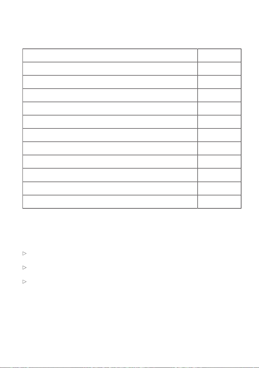
Package
Description Quantity
Wallbox 1 x
Installation instructions 1 x
Operating instructions 1 x
Drilling template 1 x
RFID card 4 x
Label with configuration information, to be kept safely 1 x
Double membrane seal M32 or ¾'' NPT (clamping area 14–21 mm) 1 x
Double membrane seal M16 (clamping area 7–12 mm) 2 x
Fastening set for wall mounting
Dowels for M8, Fischer UXR-10 4 x
Wafer-head screw 4 x
Warranty
MINI Service can provide more information on the terms of the warranty. However, the following cases
are not covered by the warranty.
Defects or damage caused by installation work which was not carried out as specified in the MINI
Wallbox Plus installation instructions.
Defects or damaged cause by the product not being used as specified in the MINI Wallbox Plus
operating instructions.
Costs and damage caused by repair work not carried out by a specialist electrician authorised by a
MINI sales outlet or authorised service workshop.
12
Page 13
OPERATION
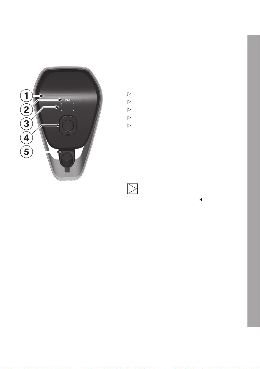
Displays and controls
Version with charging socket
The Wallbox is fitted with a charging socket
including shutter (additional contact protection).
Functions:
Charging electric or plug-in hybrid vehicles
Network connection using LAN
Local smartphone app
RFID functionality
Domestic connection monitoring (post-meter
fuse) using a directly connected Modbus RTU
(RS485) electricity meter
1 Status LED
2 RFID status indicator
3 RFID reading area
4 Charging socket with shutter
5 Charging cable plug holder
Note
No charging cable is included; a separate
charging cable is required.
13
EN
Page 14

SPECIFICATIONS
General criteria for selecting an installation site
The Wallbox has been designed for indoor and outdoor use. It is therefore necessary to ensure the
correct installation conditions and protection for the device at the installation site.
Take into account the local electrical installation regulations, fire prevention regulations and
accident prevention regulations as well as the rescue routes at the site.
Do not install the Wallbox at locations:
Which are used as escape and rescue routes.
Which are inside potentially explosive zones (EX environment).
At which the Wallbox is exposed to ammonia or ammonia gases (for example in or near
stables).
At which the Wallbox may be damaged by falling objects (for example suspended ladders or
car tyres).
At which the Wallbox is on a direct personnel route and people could stumble over the
connected charging cable.
At which the Wallbox may be struck by jets of water (for example due to neighbouring manual
car wash systems, pressure washers or garden hoses).
At which the installation surface does not have sufficient strength to withstand the mechanical
stresses.
If possible install the Wallbox so that it is protected from direct rainfall so as to avoid the effects of
weather, icing, damage by hailstones or the like.
If possible install the Wallbox so that it is protected from direct sunlight to prevent the charging
current being reduced or the charging process being interrupted as a result of excessive
temperatures on components of the Wallbox.
Comply with the permitted ambient conditions, see section Technical data.
Ensure compliance with national and international installation standards and regulations, for
example IEC 60364-1 and IEC 60364-5-52.
Ensure compliance with national regulations (for example the charging column regulation
in Germany) for the implementation of the EU Directive (2014/94/EU) relating to the
binding minimum technical specifications for sockets and vehicle couplings for charging
electric or plug-in hybrid vehicles in areas accessible to the public. This regulation relates to
charging points on public land as well as department store or customer car parks, for example.
Charging points on private carports or private garage entrances are not generally publicly
accessible charging points in terms of this regulation.
Note
If the device is installed in a location where it is not protected from the weather, for example in
an outdoor car park, the charging current will be reduced to 16 A if the temperature exceeds
the limit value.
14
Page 15

Specifications for the electrical connection
When it is delivered, the Wallbox is set to 10 A.
Make sure that you set the maximum current to suit the installed circuit breaker using the DIP
switches, see section DIP switch settings.
Selecting the residual-current-operated circuit breaker
The supply cable must be permanently wired into the existing building installation and comply with the
national statutory regulations.
Each Wallbox must be connected using a separate residual-current-operated circuit breaker. No
other circuits may be connected to this residual-current-operated circuit breaker.
RCCB at least Type A (30 mA trip current).
Additional action has been taken in the device to provide protection in the event of DC fault current
(>6 mA DC). In addition, the specifications of the vehicle manufacturer must be observed.
The rated current IN must be selected to suit the circuit breaker and the back-up fuse.
Selecting the circuit breaker
When selecting the circuit breaker, also take the increased ambient temperatures in the control cabinet
into consideration. In certain circumstances this may require a reduction in the charging current to
increase the system availability.
Set the rated current to suit the model plate details in conjunction with the required charge rating (DIP
switch settings for the charging current) and the supply cable.
Selecting the supply cable
When selecting the supply cable, take into account the possible reduction factors and the increased
ambient temperatures in the internal connection area of the Wallbox, see the temperature rating of the
supply terminals. In certain circumstances this may require an increase in the cable cross-section and
an adjustment in the temperature resistance of the supply cable.
Mains isolation device
The Wallbox does not have its own mains switch. The residual-current-operated circuit breaker and/or
the circuit breaker in the supply cable are used as a mains isolation device.
EN
15
Page 16
INTEGRATION OF EXTERNAL METERS
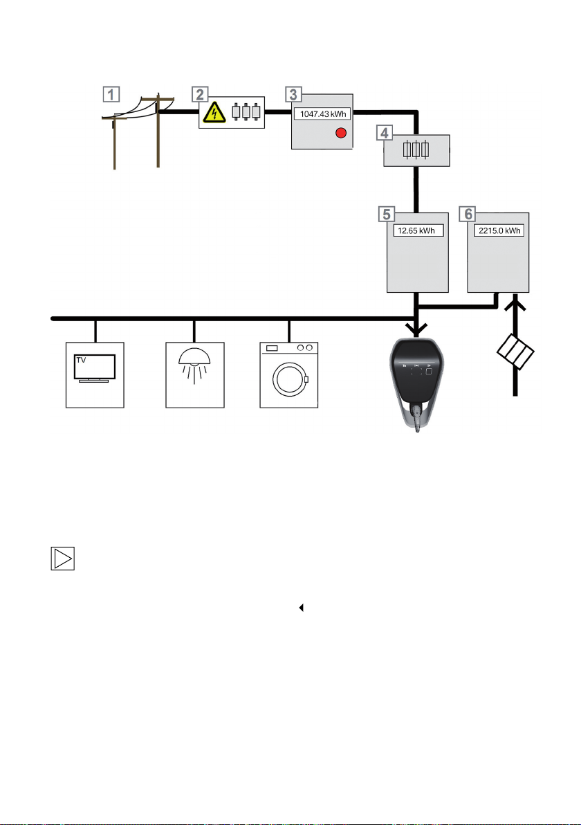
1 Public mains supply 4 Post-meter fuse
2 Pre-meter fuse (reinforced fuse, SLS switch,
etc.)
3 Mains operator's electricity meter 6 Meter 2 (optional, photovoltaic meter)
Note
This sample circuit diagram provides a system overview and does not contain all the additional
equipment required for operating the system safely (circuit breakers, RCCB, etc.). The PV
power supply may also take a different form.
5 Domestic connection meter
Domestic connection monitoring (post-meter fuse)
The domestic connection monitoring function charges the car dynamically at any time using the
available charging current depending on the other consumers on the domestic connection. This
ensures that the domestic connection fuse is not overloaded and a lower charging capacity than
possible for the car and the installation does not generally have to be selected.
16
Page 17

The Wallbox receives all its current power from the power supply through meter 5. This information
in combination with the value for the post-meter fuse 4 defined using the DIP switches enables the
Wallbox to control the charging current such that the maximum power consumption never exceeds the
post-meter fuse value.
Installation of external meters
The meter can be connected to the Wallbox Plus via RS485 (Modbus).
The installed meters must be connected with the same phase sequence as the Wallbox so that the
domestic load calculation can be performed correctly. If the Wallbox has to be connected starting with
phase 2 to ensure better division of the phase loads, the meters must also be connected starting with
phase 2.
Note
Detailed information on the meter installation is available in the installation instructions provided
by the meter manufacturer.
Note
The meter values may undergo a plausibility check after connection using the Wallbox web
interface. Information on the Wallbox web interface is provided in the operating manual for the
MINI Wallbox in the section headed "Configuration".
Meters with Modbus RTU (RS485) interface
Using this interface it is possible to operate multiple meters from different manufacturers on a single
bus. A separate cable is required from the Wallbox to the domestic installation for connection. The
advantage compared to network-capable Modbus TCP meters is the fact that it is not dependent
on additional infrastructure such as routers. This ensures high operational reliability if the cabling is
correct.
A detailed description of the connection of Modbus RTU meters via RS485 is provided in the section
RS485 connection X2.
Note
The permitted fuse value must be set using the DIP switches in the connection area of the
Wallbox, see section DIP switch settings.
The current list of supported meters can be found on the BMW Service page for charging products at
https://charging.bmwgroup.com/web/wbdoc/.
EN
17
Page 18

DIP switch settings
The use of the domestic connection monitoring
function with RS485 meters must be selected
using a DIP switch setting and does not come
into effect until the Wallbox has been restarted.
If no meter 5 is found when the ModBus function
has been enabled, the charging current is
reduced to 10 A.
No monitoring: DSW1.2 = OFF (default)
Monitoring function: DSW1.2 = ON
This reduction is also visualised on the Wallbox
status LED. Further information is provided in the
Wallbox operating manual.
18
Page 19

INSTALLATION
Note
The maximum charging current of the Wallbox on delivery is set to 10 A.
Installation requirements
Follow the local installation regulations.
The electrical connection (supply cable) must be prepared.
Acclimatisation: If there is a temperature difference of more than 15 °C between transport and the
installation site, the Wallbox must be acclimatised unopened for at least two hours.
Opening the Wallbox immediately may result in condensation formation in the interior and
cause damage when the device is switched on. In certain circumstances, damage caused by
condensation formation may also not appear until a later date after the installation.
Ideally, the Wallbox should be stored for a few hours in advance at the installation site. If this is not
possible, the Wallbox should not be stored in low temperatures (< 5 °C) overnight outdoors or in a
vehicle.
Tool list
The following tools will be required for the installation work:
Slotted screwdriver for supply terminals, blade width 5.5 mm
Phillips screwdriver PH2
LSA+ insertion tool for connecting the mains cable
Torx screwdriver T40
19
EN
Page 20
Recommended installation positions
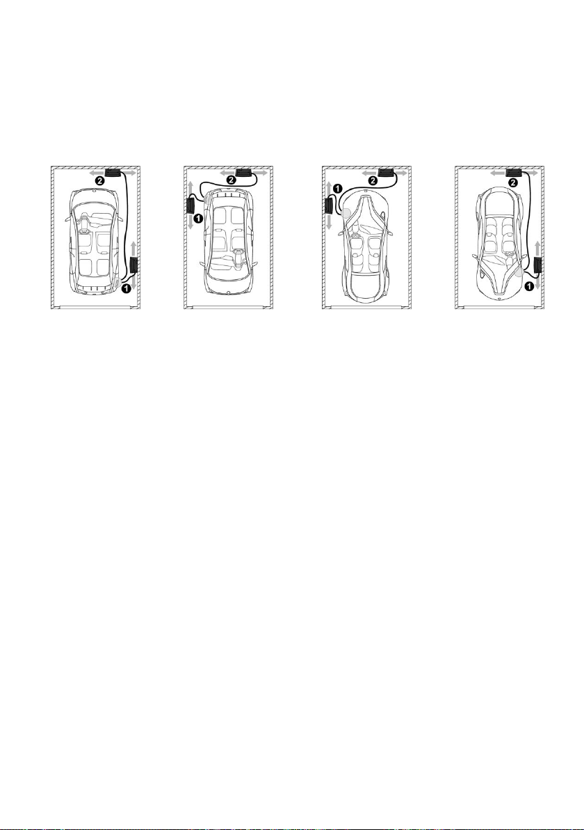
When selecting the installation position, taken note of the position of the charge connector on your
vehicle and the direction in which you normally park it. Examples:
BMW i3 BMW/MINI PHEV
1 Recommended installation position
2 Alternative installation position
20
Page 21
Required distance
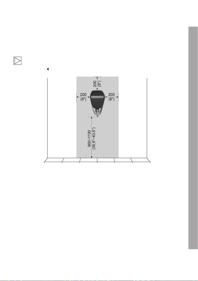
The distance shown below (hatched area) will ensure easy installation and operation of the Wallbox.
If several Wallboxes are installed next to each other, a distance of at least 200mm (8") must be left
between them.
Note
The installation height must be complied with to meet the requirements for both indoor and
outdoor use.
Dimensions in millimetres (inches)
EN
21
Page 22
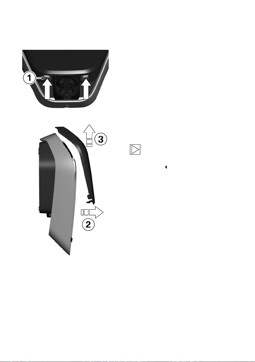
Remove the housing cover
1. Press the two locks 1 for the housing cover on
the underside of the Wallbox upwards.
The housing cover should then jump out
slightly at the bottom.
2. Swing the housing cover forwards a little on
the underside 2.
3. Then release the housing cover by raising it 3.
Note
Keep the housing cover in the packaging to
prevent it being scratched or suffering other
damage.
22
Page 23
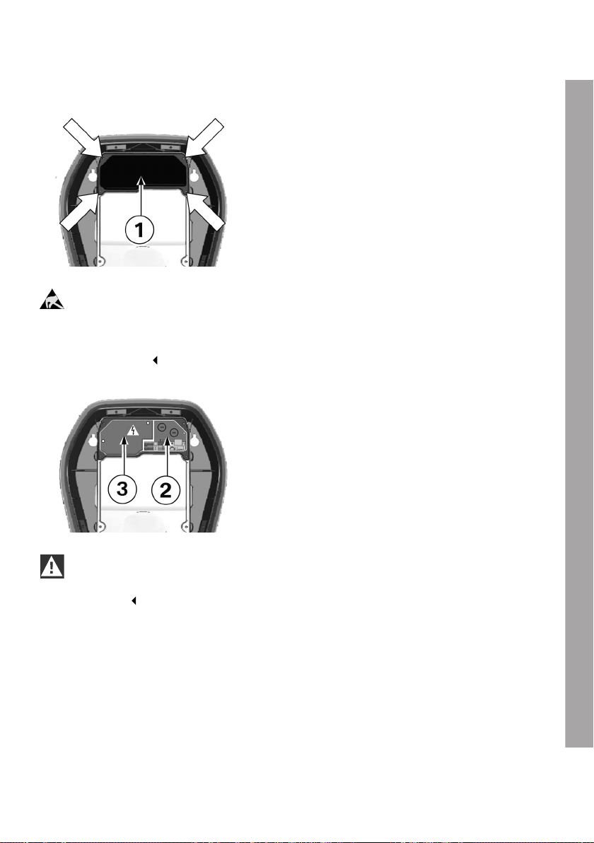
Removing the termination panel cover
1. Undo the four screws used to secure the
termination panel cover 1.
ESD
Danger of damage. Electronic components may be destroyed if touched.
Before handling modules, perform an electrical discharge process by touching a metallic
earthed object.
2. Remove the termination panel cover. The
termination panel 2 is now accessible.
3. Remove the silica bag from the terminal panel
and dispose of it properly.
WARNING
The cover over the connection area 3 for the mains voltage may only be removed by a qualified
electrician.
EN
23
Page 24
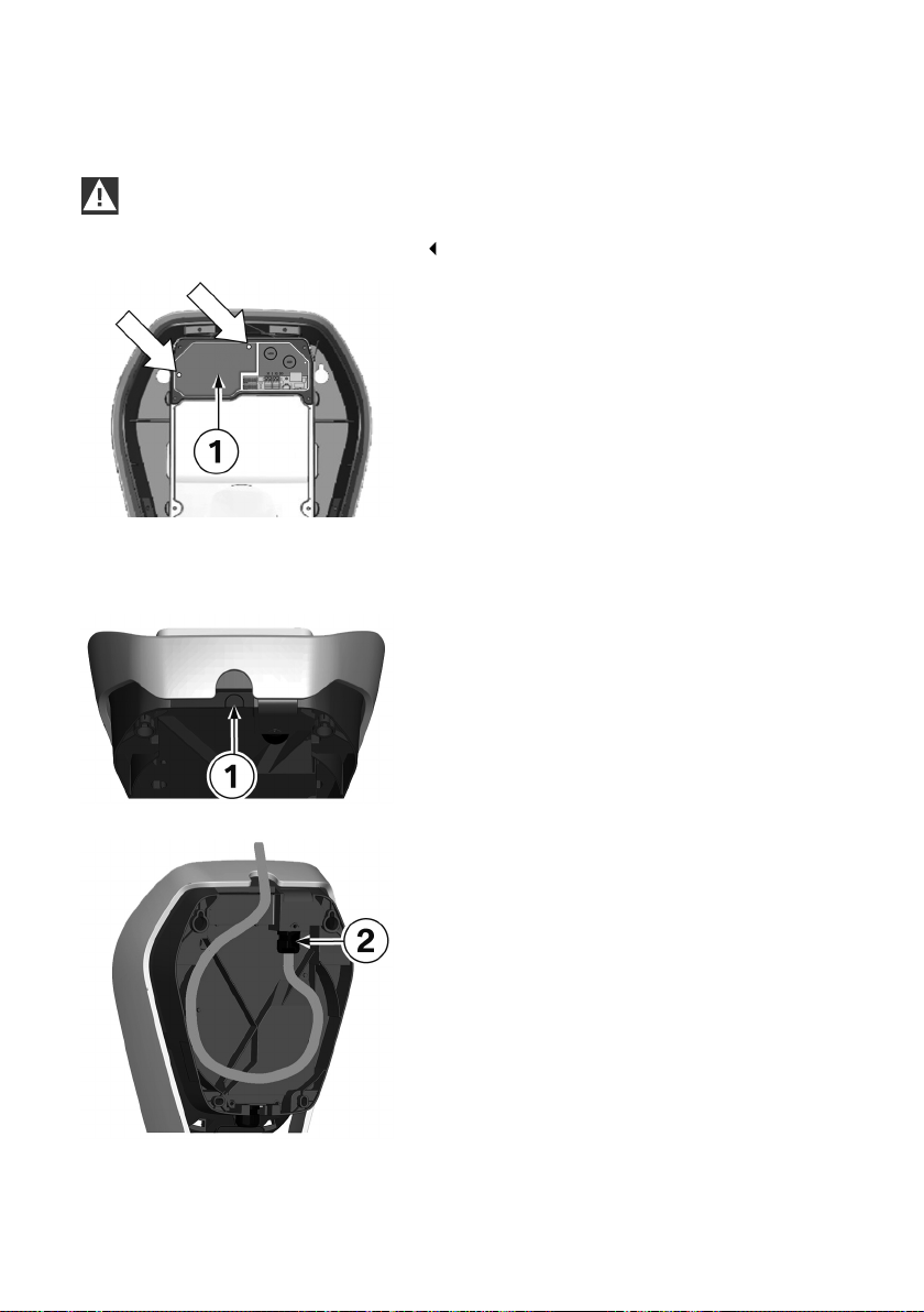
Removing the terminal cover
WARNING
Electrical danger. The terminal cover may be opened only by authorised electricians with the
appropriate training and qualifications.
1. Undo the to fastening screws on the terminal
cover 1.
2. Remove the terminal cover over the supply
terminals.
Surface-mounted cable routing - Cable inlet from above
The connection cables can be inserted from
above through the housing opening in the outer
frame.
1. To do this, break out the marked position 1 on
the inner housing section.
24
2. Lay the supply line in a loop to the cable gland
2.
Observe the permissible bending radii of the
cable.
Page 25
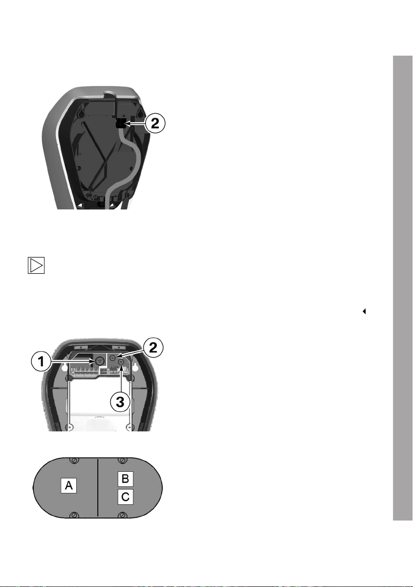
Surface-mounted cable routing - Cable inlet from below
1. Lay the supply line in a loop to the cable gland
2.
Observe the permissible bending radii of the
cable.
Cable inlet from behind – cable in the wall
Note
The cable is to be inserted straight out of the wall into the rear of the device. Ensure that the
Wallbox is correctly positioned so that the cable opening is directly above the cable. Ensure
that you comply with the minimum bending radii. Use the drilling template with the appropriate
punching for the cable to ensure the correct alignment of the Wallbox above the wall outlet.
Cable openings
1 Bushing/Double membrane seal M32, supply
cable
2 and 3 Bushing/Double membrane seal M16, for
control cable/Ethernet
Flush-mounted socket
A double flush-mounted socket with a separating
web may be used for safe separation.
A Supply cable
B Control cable
C Ethernet
EN
25
Page 26
Cable openings
Break off cable openings
1. Place the housing on a stable surface.
2. Carefully remove the required cable openings
using a hammer and slot head screwdriver.
3. Then insert the appropriate bushings, cable
glands or double membrane seals.
4. Fit the Wallbox with the supplied cable glands
or blind glands if a cable opening is no longer
to be used.
26
Page 27
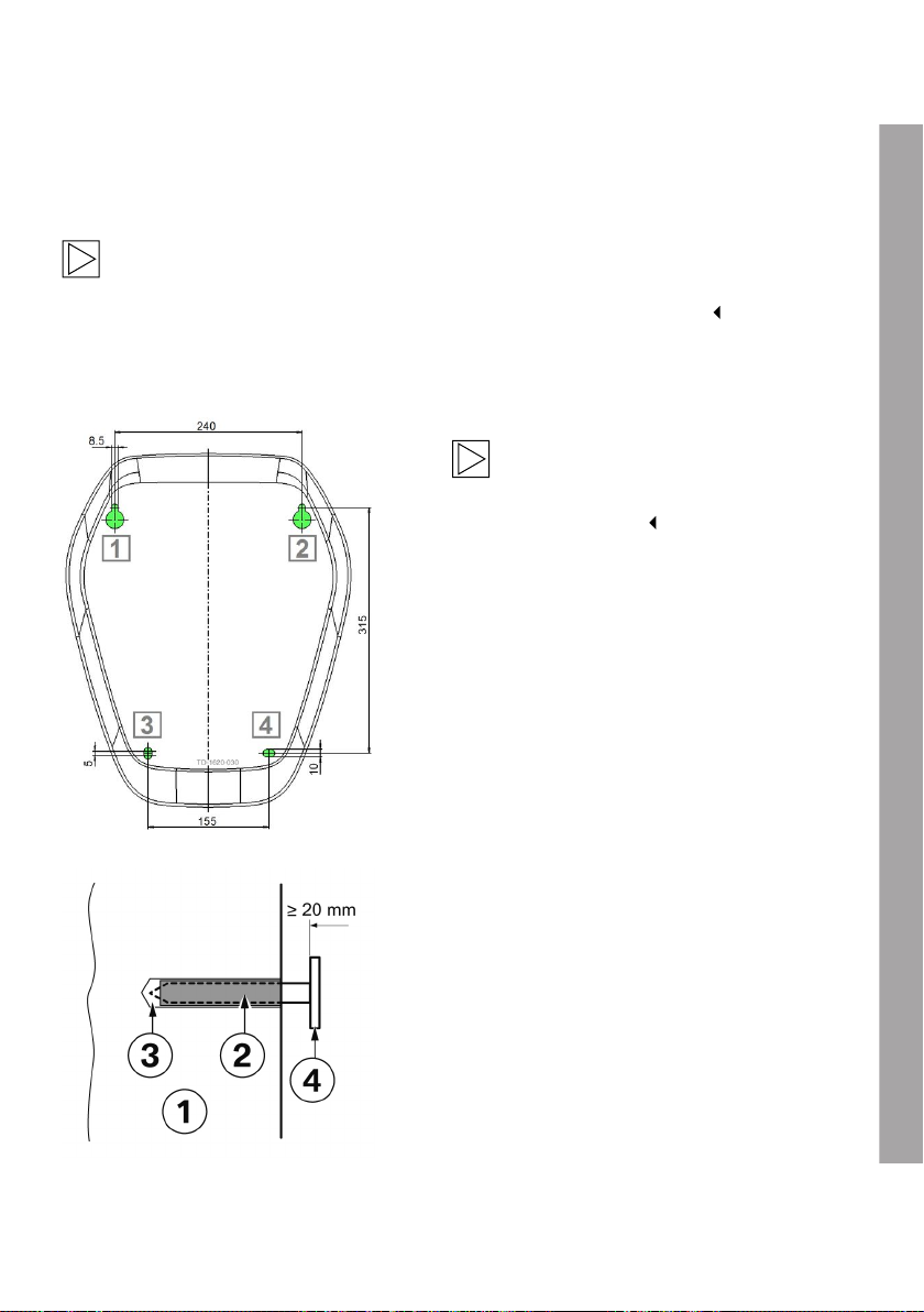
Mounting the Wallbox
The supplied mounting material is suitable for concrete, brick and wood (without rawl plugs). If the
surface is different, a suitable type of mounting must be selected.
Note
The fastening materials must be provided by the customer for different surfaces. Correct
installation is essential and is not the responsibility of the device manufacturer.
Assembly preparations
Drill holes
Note
Observe the installation height.
Upper edge of the drilling template =
1500 - 1700 mm.
1. Draw the four drill holes 1 to 4 using the
enclosed drilling template and a spirit level.
2. Drill the mounting holes.
3. Insert the rawl plugs.
Upper fastening screws
1. Screw in the two top wafer-head screws, with a
distance to the wall ≥ 20 mm.
1 Wall
2 Rawl plug
3 Drill hole
4 Wafer-head screw
27
EN
Page 28
Installation on cavity walls
For installation on cavity walls, at least two
fastening screws, for example 1 and 2, must be
fastened to a solid element in the wall.
Special cavity wall rawl plugs must be used for
the other fastening screws.
Note
When mounting on cavity walls, special
care must be taken to ensure that the
structure has sufficient load-bearing
capacity.
Insert the supply cable
General information
Use a suitable cable sheath diameter on the supply cable or increase the cable sheath diameter
using suitable sealing adapters.
Insert the supply cable a sufficient way into the cable gland or double membrane seal. The cable
sheath must be visible in the connection zone.
The installation pipe or empty pipework with the supply cable must not be screwed into the cable
gland or fed through the double membrane seal.
The supply cable must be routed in a straight line not exceeding the bending radii (approximate
cable diameter times 10) through the cable gland or double membrane seal.
The cable gland or double membrane seal must be installed correctly and adequately secured.
28
Page 29
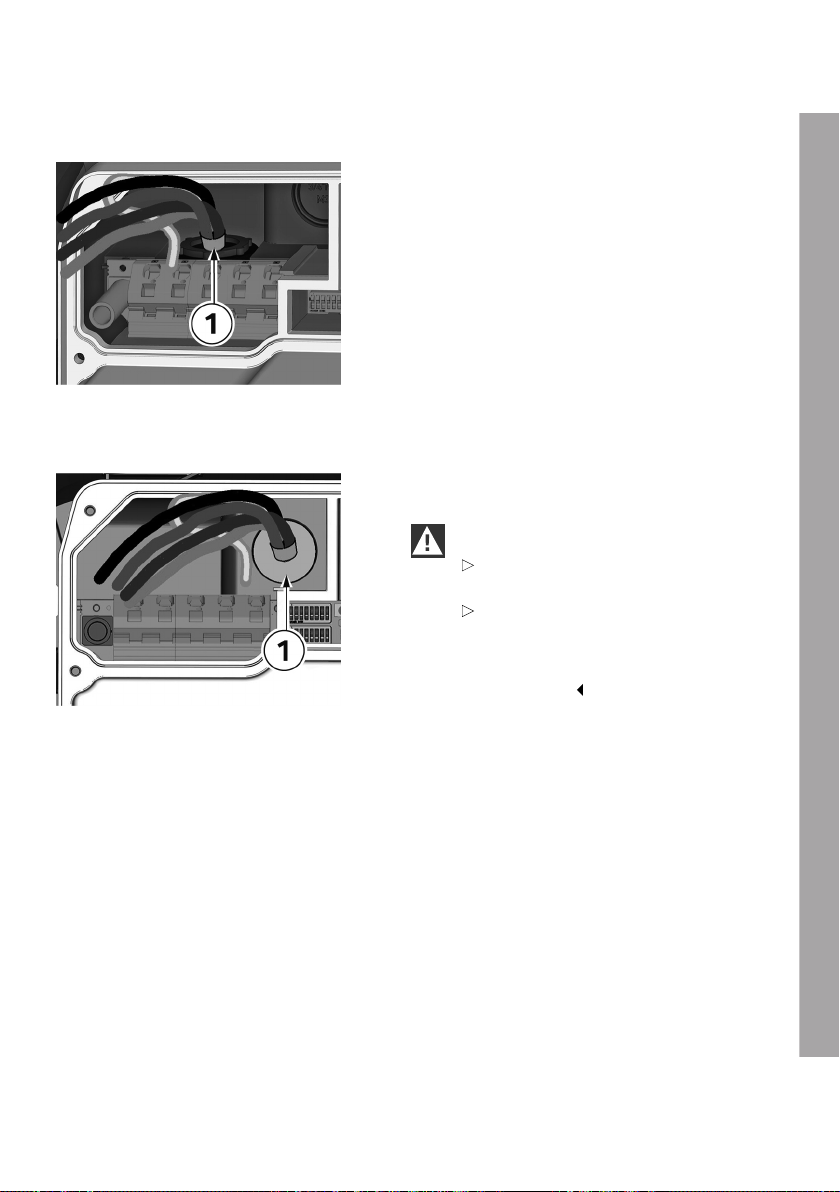
Cable routing from above/below
1. Route the supply cable through the cable
gland and tighten the gland.
The cable sheath 1 must be visible in the
connection zone.
Cable routing from behind (flush-mounted)
1. The supply line must be routed through the
bushing/double membrane seal 1 as shown.
IMPORTANT
Make sure that the double membrane
seal fits neatly against the cable sheath.
Make sure that the supply line
is inserted centrally, straight and
pressure-free through the double
membrane seal and that a tight fit is
guaranteed.
Inserting additional cables
1. Run the required additional cables, such as the bus cable for external electricity meters or
Ethernet, into the connection zone of the Wallbox.
2. Use the supplied double membrane seal M16 to seal the bushing.
EN
29
Page 30
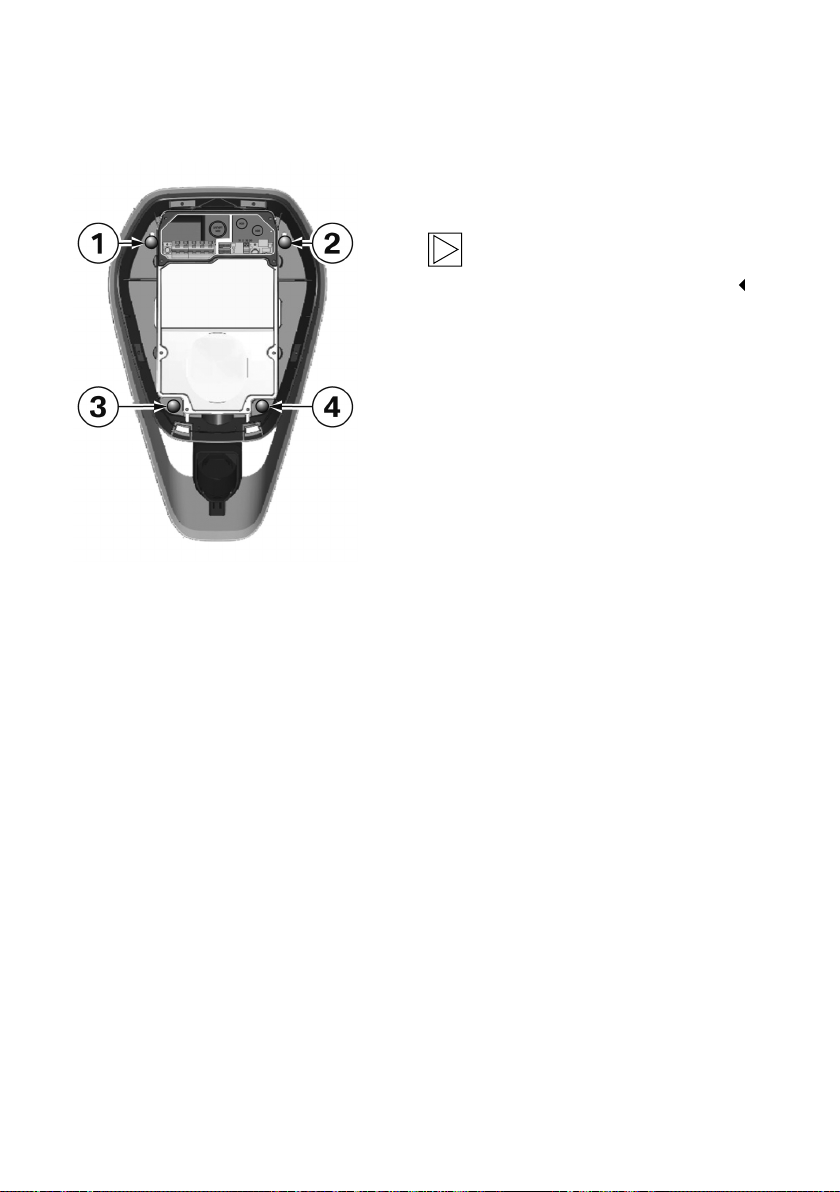
Mounting the Wallbox
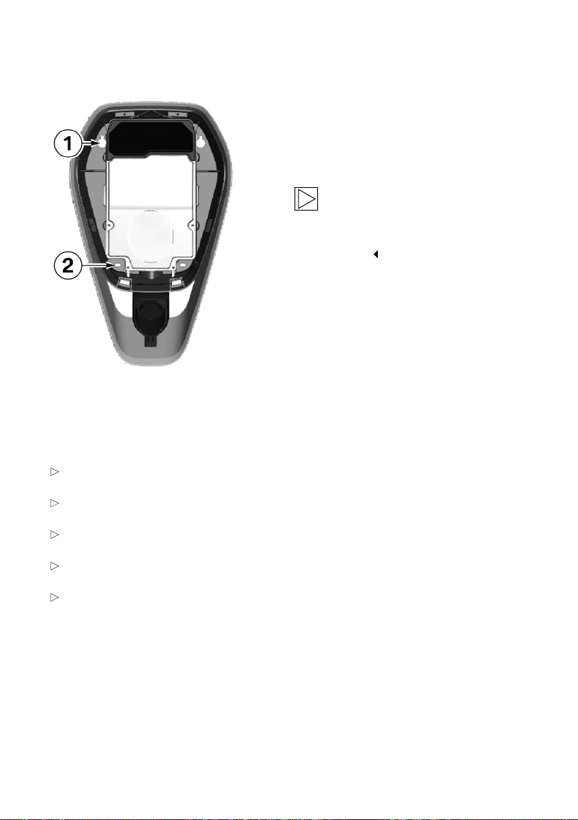
1. After the cables are inserted, mount the
Wallbox onto the two top wafer-head screws 1
and 2.
Note
Ensure that the supply cable is correctly
routed to the rear and is not jammed.
2. Tighten the wafer-head screws 1 and 2.
3. Then secure the Wallbox with the two bottom
wafer-head screws 3 and 4.
4. Wrap the charging cable around the Wallbox for
safe storage, see operating instructions.
30
Page 31
ELECTRICS
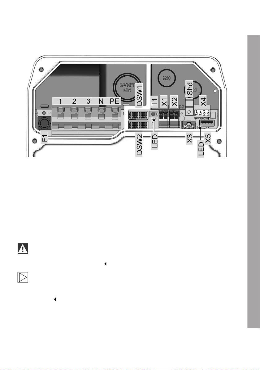
Connection diagram with open termination panel cover
1 Mains connection outer conductor 1 T1 Service button
2 Mains connection outer conductor 2 LED Status LED, internal
3 Mains connection outer conductor 3 X1 Enable input
N Mains connection, N conductor X2 RS485 connector
PE mains connection, PE conductor X3 Diagnostic connector, RJ45
F1 Fuse holder X4 Ethernet1 connector, LSA+ terminals
DSW1 DIP switch for configuration X5 USB connector
DSW2 DIP switch for addressing Shd Shield connection for Ethernet1
connection terminals
IMPORTANT
The X3 diagnostic connection is suitable only for error analysis and must not be used to
connect the device to a network.
Note
The connection overview shows all the options of the device, but the legend only lists the
available options. It is possible that your version of the device will not have all the connections
available.
EN
31
Page 32
Connecting the supply cable
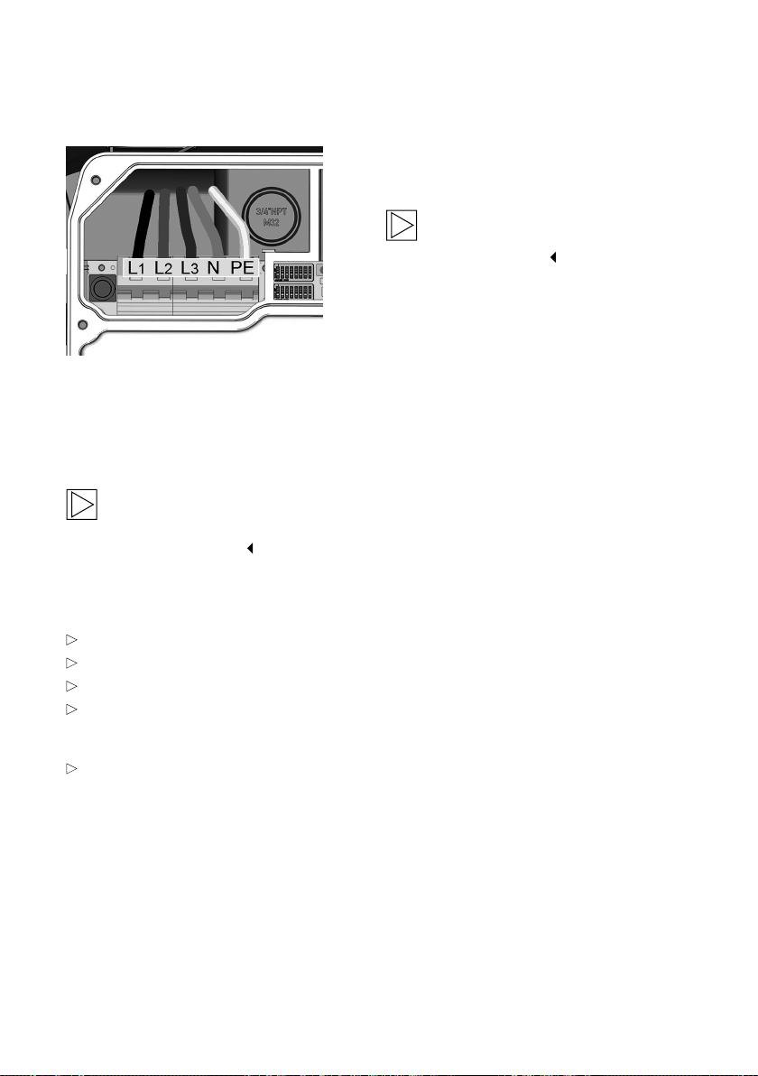
1. Cut the connecting wires to the appropriate
length. They should be kept as short as
possible.
Note
The PE conductor must be longer than the
other conductors.
2. Strip approximately 12 mm of insulation of the
connecting wires. We recommend the use of
wire-end ferrules for fine connecting wires.
3. Connect the supply cable L1, L2, L3, N and
PE.
1-phase connection
It is also possible to connect the Wallbox on a
1-phase basis. Use terminals L1, N and PE for
this purpose.
Note
Make a note of which outer conductor you connect to terminal L1 if you are installing multiple
Wallboxes in a group.
Technical data of the connection terminal
Rigid (min.-max.): 0.2 – 16 mm²
Flexible (min.-max.): 0.2 – 16 mm²
AWG (min.-max.): 24 – 6
Flexible (min.-max.) with wire-end ferrule:
without/with plastic sleeve
0.25 – 10/0.25 – 10 mm²
Stripping length: 12 mm
32
Page 33
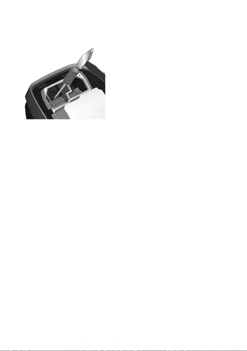
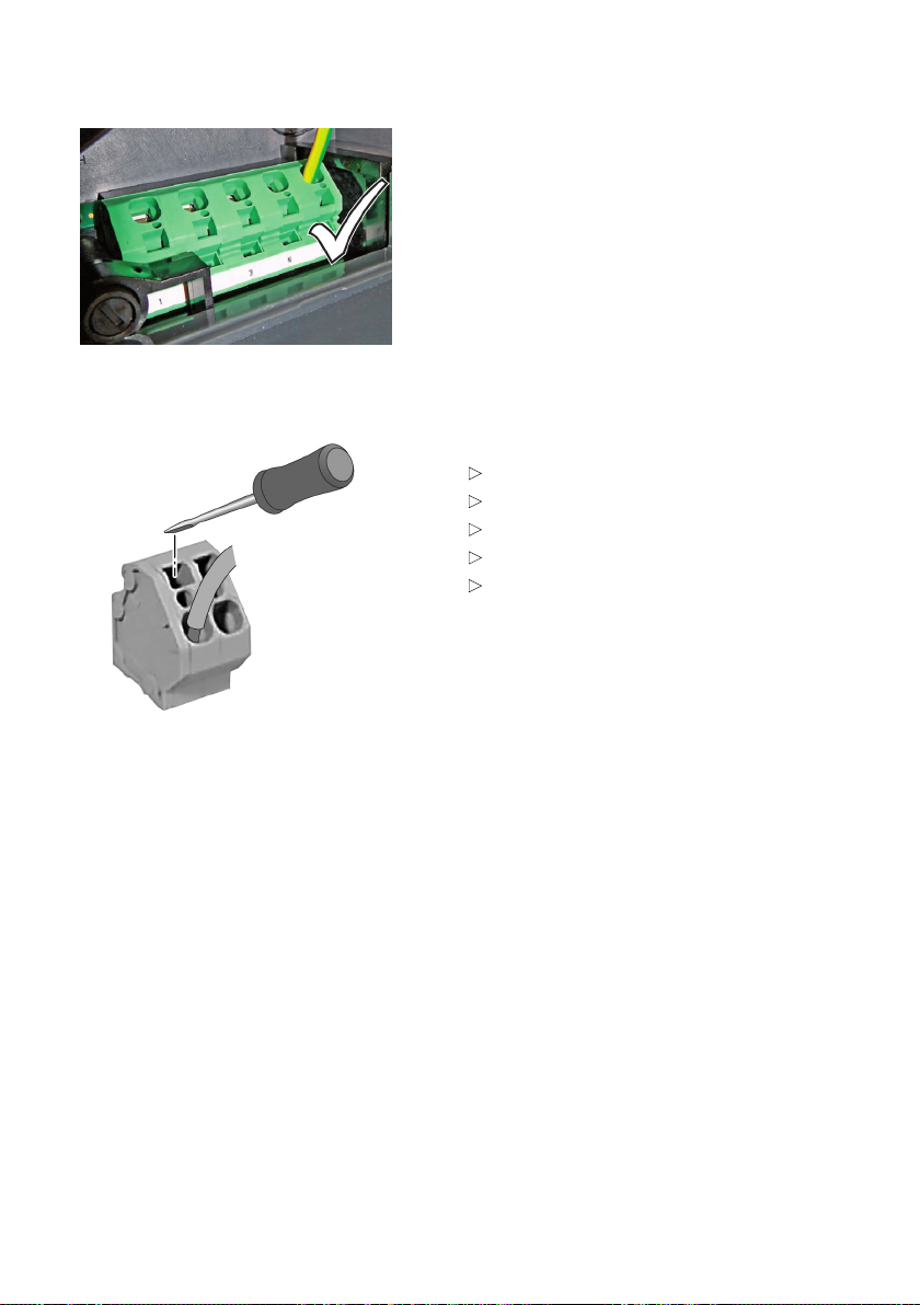
Using the supply terminals (spring-type terminal)
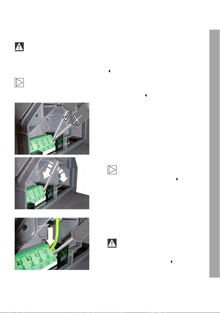
IMPORTANT
This terminal is not a clamp-type terminal and must be activated for the connection.
If the terminal is not completely opened before the cable is connected, it is possible that the
device will function when it is commissioned but is then damaged during the first charging
cycle with high current through overheating.
Note
Danger of breaking the terminal.
Do not lever the screwdriver upwards, downwards or to the side.
Open the supply terminal
1. Slide a slotted head screwdriver with a width of
5.5mm, as shown in the illustration, into the
supply terminal.
2. Press the screwdriver into the supply terminal.
Note
As you press the screwdriver into the
terminal, its angle will change.
Connect the wire
1. Slide the stripped connecting wire into the
supply terminal.
IMPORTANT
If you attempt to slide in the wire when the
terminal is not open, there is a risk of fire
due to inadequate contact.
EN
33
Page 34
Terminals X1/X2
Close the supply terminal
1. Pull the screwdriver fully out of the terminal to
close the contact.
2. Check that the connecting wire is secure.
3. Connect the other connecting wires in the
same way.
Terminal data for X1/X2
Spring-type terminals
Cross-section (min.-max.): 0.08 – 4 mm²
AWG (min.-max.): 28 – 12
Stripping length: 8 mm
Slotted screwdriver: 3.0 mm
34
Page 35
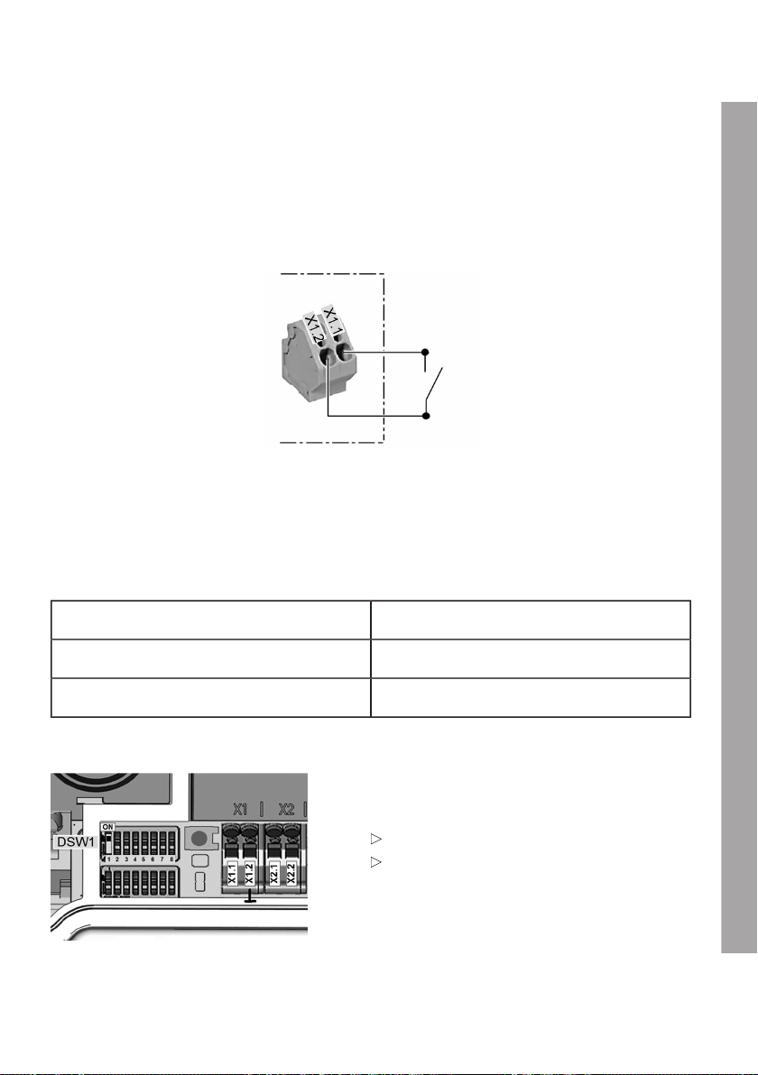
Enable input X1
The enable input is designed for use with a floating contact. Using the enable input, it is possible
to control the Wallbox using external components (for example an external key switch, ripple control
receiver from the power supplier, domestic controller, time switch, combination lock, photovoltaic
system, etc.).
Circuit diagram:
Electrical requirements/Connection:
Safe isolation from dangerous voltages must be ensured outside the device for this control cable.
1. Connect the wires on enable input X1 as shown in the circuit diagram.
Logical function:
Enable contact Status of Wallbox
Open DISABLED
Closed READY
DIP switch setting:
The use of the enable input must be activated by
a DIP switch setting.
Use enable input:
Yes: DSW1.1 = ON
No: DSW1.1 = OFF (default)
EN
35
Page 36
RS485 connection X2
Note
A detailed description for using this function is provided in the section entitled Domestic
connection monitoring (post-meter fuse).
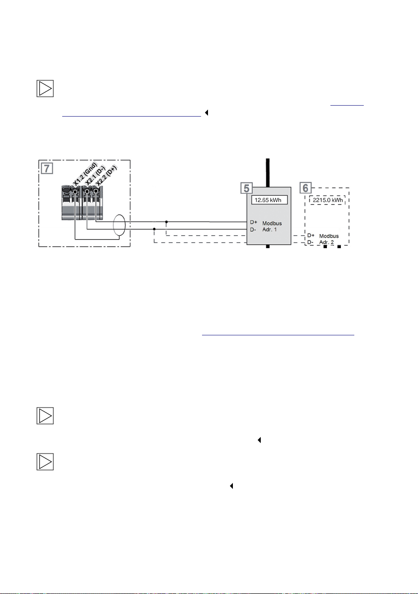
Schematic diagram
5 Meter 1 (domestic connection meter) 7 Wallbox connection terminal block
6 Meter 2 (optional, photovoltaic meter)
The RS485 connection X2 is used for communicating with up to two smart electricity meters using
the Modbus protocol (for a list of supported types and the corresponding parameters and terminal
assignments for the installed meter, see section Meters with Modbus RTU (RS485) interface). In
addition to the RS485 data cables on terminal X2.1 and X2.2, there is an earth connection available
on terminal X1.2 (Gnd) for the cable shield. We recommend that you use a shielded, twisted
connection cable (>0.5mm²).
The cable shield must not be connected to the protective conductor potential (for example, Shd
connection) at any other point. The Gnd is to be connected to the meter depending on availability.
Note
Terminal X1.2 (Gnd), the Gnd cable on the RS485 cable or its shield must not be routed on
the shield support Shd of the Ethernet1 connection X4.
Note
Detailed information about the electrical connection of the meter is provided in the installation
instructions supplied by the meter manufacturer.
36
Page 37
Electrical requirements/Connection
1. Connect the wires on the RS485 connections X1 and X2 as shown in the circuit diagram. Safe
isolation from dangerous voltages must be ensured outside the device for this control cable.
2. Set the meters used as shown in the table, see Meters with Modbus RTU (RS485) interface. Refer
to the installation instructions provided by the meter manufacturer for this purpose.
Ethernet1 connection X4
The Ethernet1 connection takes the form of a terminal block in LSA+® form. Permanently wired
communication can be enabled using the Ethernet1 connection.
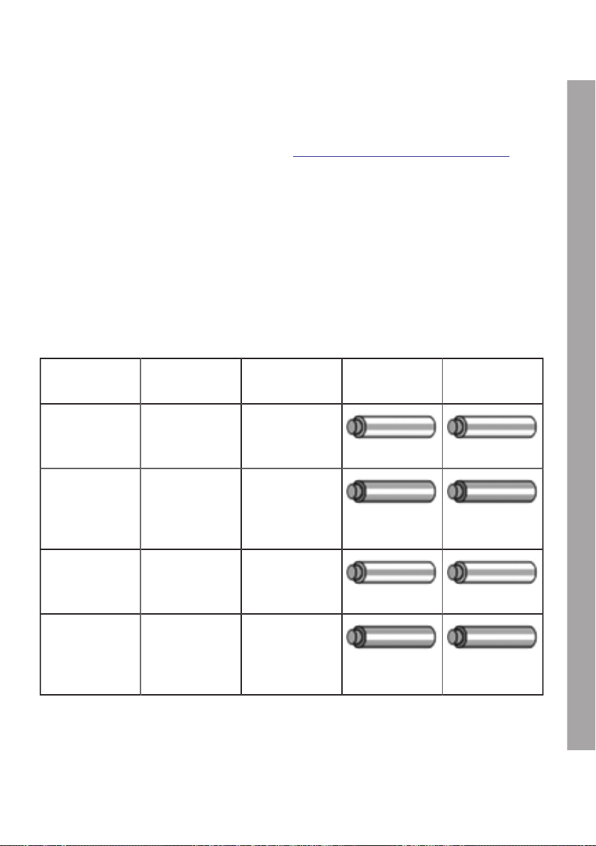
Colour coding
To suit the cabling standard used in the building, the contacts are wired in accordance with
TIA-568A/B for 100BaseT as follows:
Pin -568A
Pair
1 (Tx+) 3 2
2 (Tx−) 3 2
3 (Rx+) 2 3
4 (Rx−) 2 3
-568B
Pair
-568A
Colour
White/Green line White/Orange line
Green/White line
or green
White/Orange line White/Green line
Orange/White line
or orange
-568B
Colour
Orange/White line
or orange
Green/White line
or green
EN
37
Page 38
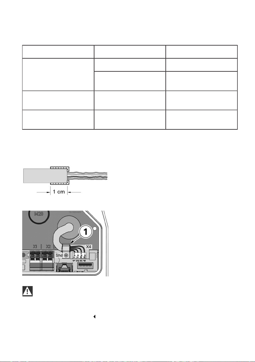
Terminal data:
Category Diameter of wire Diameter of insulation
0.36 mm (AWG 27) 0.7 – 0.75 mmRigid cable
Cat 5e / Cat 6 STP
0.4 – 0.64 mm
(AWG 26 – AWG 22)
0.7 – 1.4 mm
Cat 6 STP 0.51 – 0.81 mm
(AWG 24 – AWG 20)
Flexible cable
Cat 5e / Cat 6 STP
Recommended tool:
KRONE LSA+ ® insertion tool for connecting the wires without solder, screws or stripping whilst at the
same time cutting off the residual length.
7 x 0.2 mm
(AWG 24)
Preparing the connection cable
1. Strip the connection cable approx. 6 cm.
2. Fold back the shield braid approx. 1 cm in full,
and wrap it with conductive textile adhesive
tape.
Connecting the cable
1. When using an STP cable, fasten the
connection cable at the place where the shield
braid is wrapped in the cable clamp 1.
The cable clamp must be screwed to the
shield connection Shd of the printed circuit
board.
2. Connect the wires to the Ethernet1 terminal
block X4 using the insertion tool.
1.0 – 1.4 mm
1.1 – 1.4 mm
IMPORTANT
Danger of damage.
Ensure that the connection area is clean so that no dirt, for example wire residues, can get into
the interior of the Wallbox.
38
Page 39
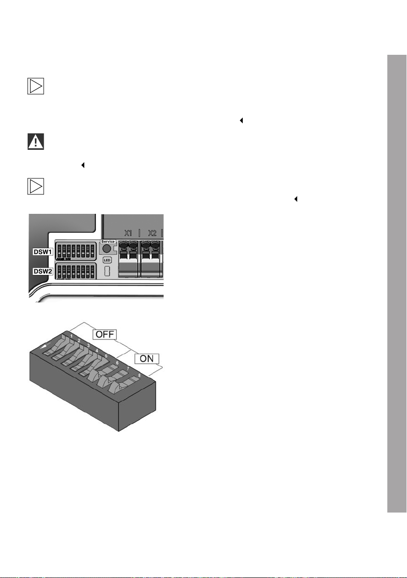
SETTINGS
DIP switch settings
Note
Changes to the DIP switch settings do not take effect until the Wallbox has been restarted! To
do so, press service button until the 1st signal tone sounds (around 2 seconds). Alternatively,
you can also switch the supply voltage off and on again.
IMPORTANT
If the Service button is pressed for too long (around 5 seconds), the RFID cards may be
deleted.
Note
Switches which are not described here must be left in the OFF position.
DIP switches
The DIP switches are used to address and
configure the Wallbox and are located under the
terminal panel cover.
DSW1: Configuration, DIP switch up
DIP switch specimen illustration
For a better explanation, the figure shows the
position of the DIP switches for the ON and OFF
states.
EN
39
Page 40
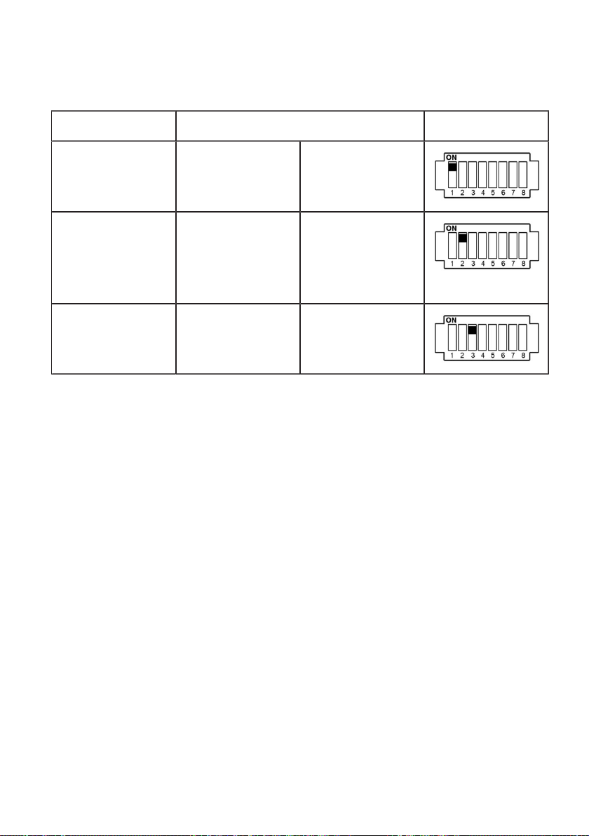
Control functions
Function DIP switch Illustration
External enable input
DSW1.1 ON = yes
[X1] is used.
Domestic connection
DSW1.2 ON = yes
monitoring is used
(RS485 connection
[X2] with Modbus
functionality).
Activate SmartHome
DSW1.3 ON = yes
and app interface via
(1)
UDP.
(1)
Access only using secure networks, in order to prevent the Wallbox being manipulated by third
parties.
40
Page 41
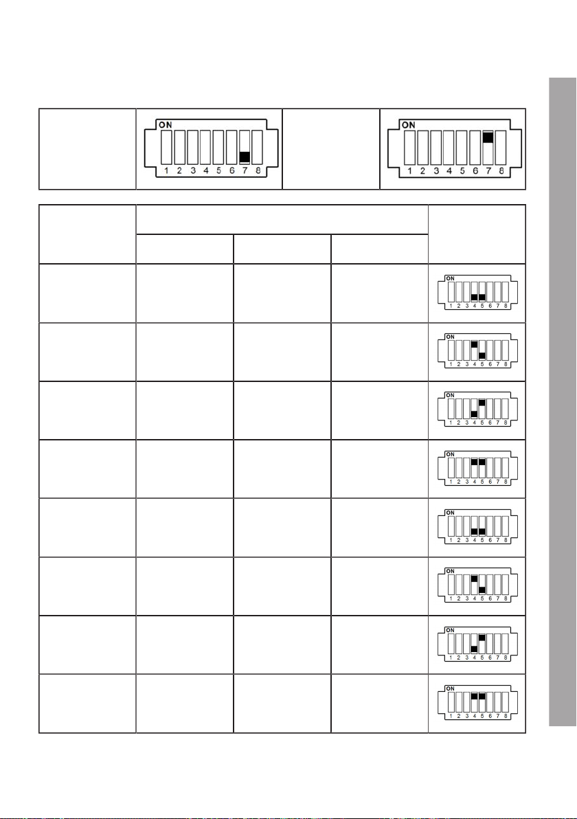
Post-meter fuse on the domestic installation (DSW1 and DSW 2)
DSW2.7 (OFF) DSW2.7 (ON)
DIP switchCurrent value
DSW2.7 DSW1.4 DSW1.5
25 A OFF OFF OFF
35 A OFF ON OFF
50 A OFF OFF ON
63 A OFF ON ON
80 A ON OFF OFF
100 A ON ON OFF
Figure (DSW1)
125 A ON OFF ON
150 A ON ON ON
EN
41
Page 42
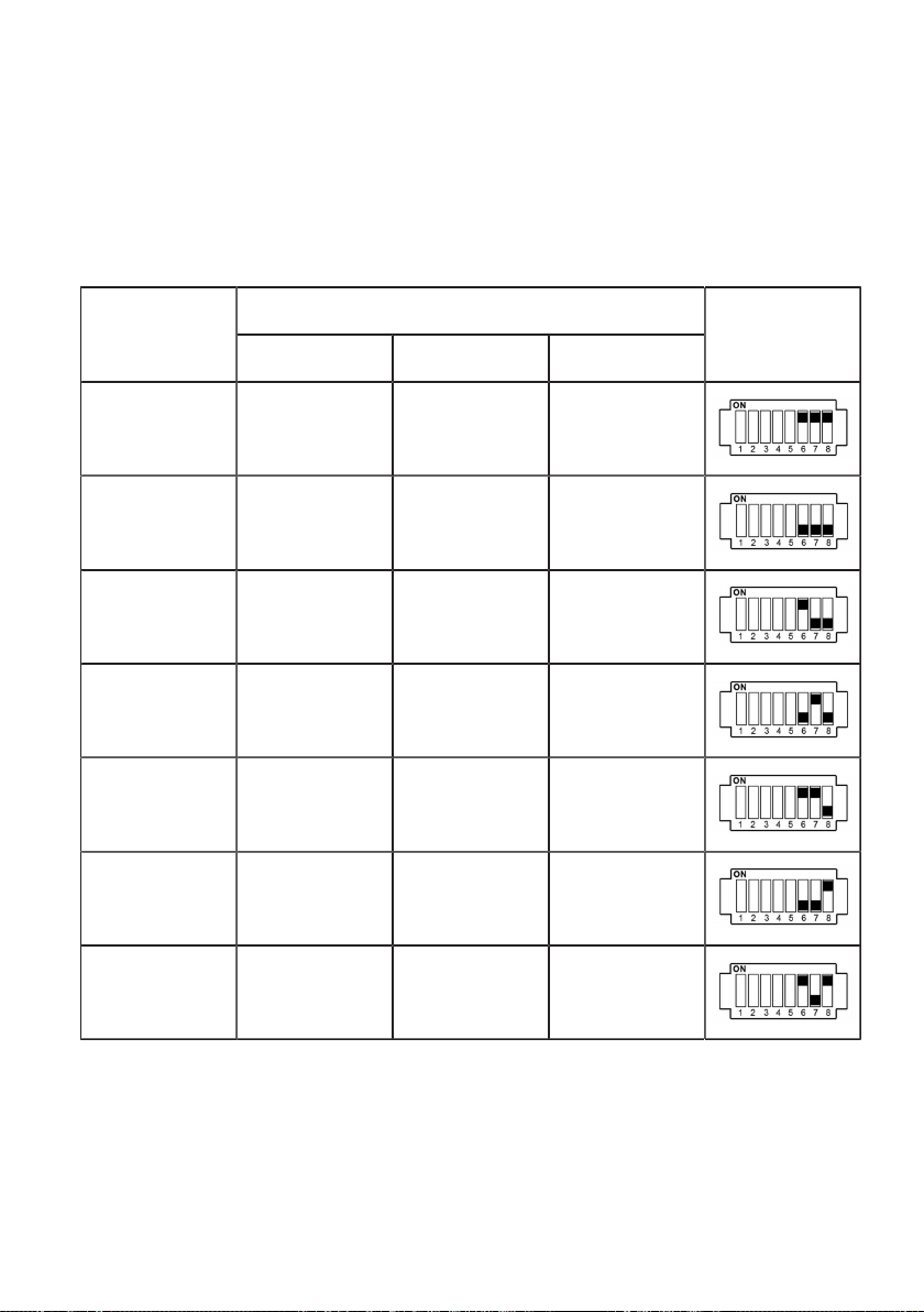
Maximum charge current (DSW1)
The following DIP switches can be used to set a maximum value for the charge current. This maximum
value is valid for each connected phase individually and not as a total value for all phases together. The
power input is transmitted to the vehicle (Control Pilot Duty Cycle). A maximum value can only be set
which is less than or equal to the operating current according to the rating plate.
DIP switchCurrent
DSW1.6 DSW1.7 DSW1.8
0 A ON ON ON
10 A OFF OFF OFF
13 A ON OFF OFF
16 A OFF ON OFF
20 A ON ON OFF
25 A OFF OFF ON
Illustration
32 A ON OFF ON
42
Page 43
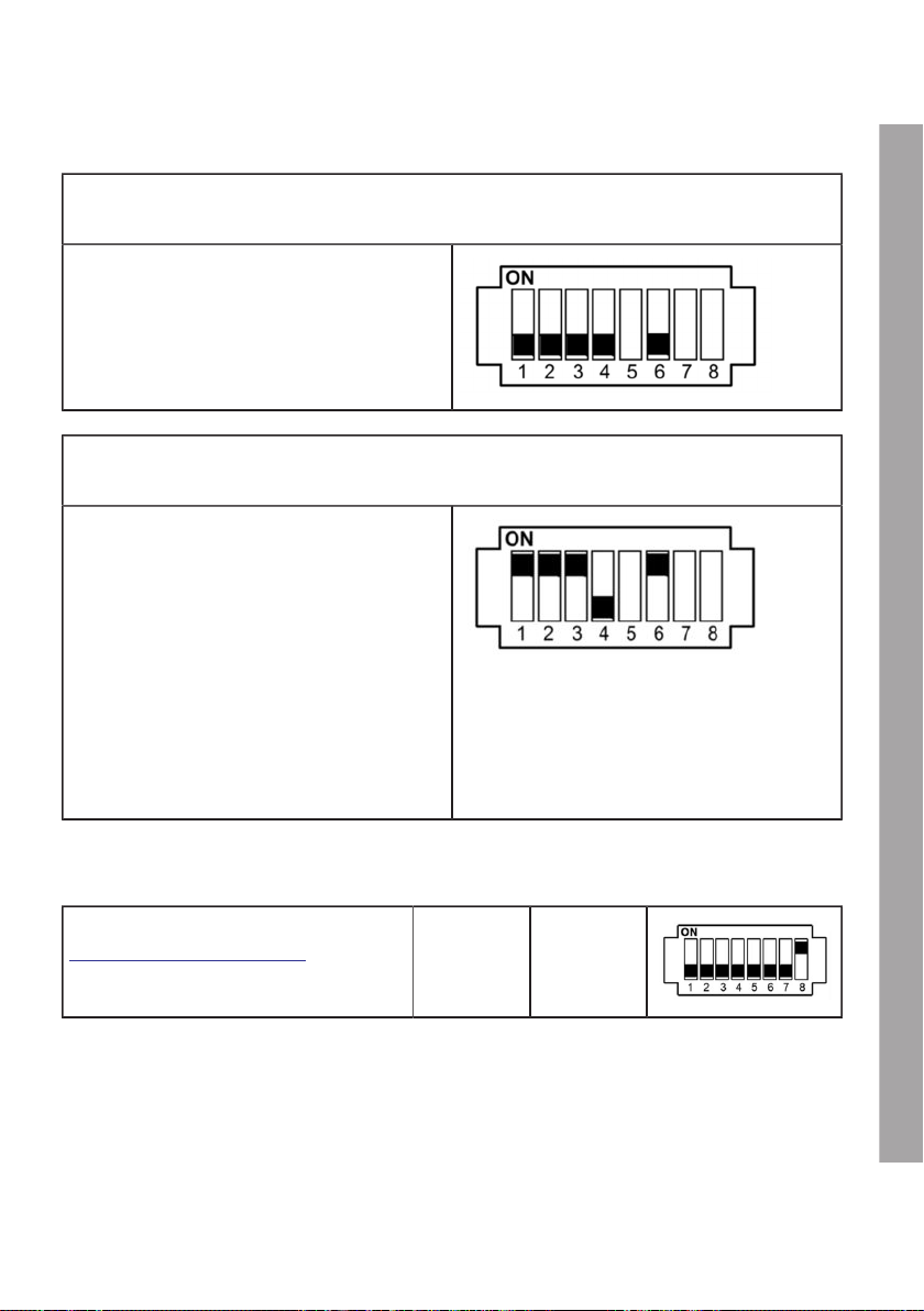
IP address (MINI Wallbox Plus)
REFER TO IP ADDRESS VIA DHCP (NO ADDRESS)
DSW2.1 to DSW2.4=OFF / DSW2.6=OFF
The Wallbox attempts to obtain an IP address
through a DHCP server. This is also the
default setting for a Wallbox without a network
connection.
USE A FIXED IP ADDRESS
DSW2.1 to DSW2.4 / DSW2.6=ON
The addressing process is completed using DIP
switches DSW2.1 to DSW2.4. The configurable
Ethernet addresses start at 10 + DIP switch
setting.
Addresses 11 to 25 can be used
[192.168.25.xx] with 4-bit addressing. Subnet
mask: [255.255.255.0]
DSW2.1 = address bit 20 (Value=1)
DSW2.2 = address bit 21 (Value=2)
DSW2.3 = address bit 22 (Value=4)
DSW2.4 = address bit 23 (Value=8)
Example for address "17":
DSW2.1 = ON (Value=1)
DSW2.2 = ON (Value=2)
DSW2.3 = ON (Value=4)
DSW2.4 = OFF (Value=0)
Address= 10 + 1 + 2 + 4 + 0 = 17
Commissioning mode (DSW2.8)
Activate commissioning mode, see section
Commissioning mode/Self-test.
DSW2.8 ON = yes
EN
43
Page 44

COMMISSIONING
General commissioning procedure
Clean the connection area (remove material residues and dirt).
Before commissioning, check that all screw and clamp connections are tight!
Check that all unused cable glands are properly sealed with dummy plugs or dummy connections.
Switch on the supply voltage. After start-up and after the self-test, the RFID status display is white.
Complete the specified initial tests in compliance with local regulations and laws.
Close the Wallbox terminal panel cover if it has been opened, see section Installing the termination
panel cover.
Install the housing cover, see section Install the housing cover.
Commissioning mode/Self-test
The Wallbox can be switched to commissioning mode to support the initial system test. A device selftest is carried out (lock, contactor control, current measurement, etc.) and an error is displayed.
After a successful test without the vehicle connected, the contactor is switched for a limited time (~10
minutes) to enable the initial tests. Normal charging is not possible in commissioning mode.
The lock on the charging socket is activated to prevent a connection (Wallbox versions with a charging
socket only).
For safety reasons, switching on the Wallbox in commissioning mode via the supply voltage leads to an
error (white-red-red-red) in order to prevent unattended activation.
Activating commissioning mode
1. Set the DIP switch DSW2.8 to ON.
2. Reset the Wallbox. To do this, press the Service button for 1second (signal tone).
Commissioning mode is now enabled and is indicated by the status LED being lit in orange.
3. It is now possible for approximately 10 minutes to contact with the measuring instrument using
standard test clips (for example Astaco® test clips from BEHA) and conduct the required safety
tests. After this time the contactor is disabled and the Wallbox switched off.
Deactivating commissioning mode
1. Set the DIP switch DSW2.8 back to OFF.
2. Reset the Wallbox. To do this, press the Service button for 1 second (signal tone) or switch the
supply voltage off and on again. The Wallbox starts up in normal operating mode and is ready for
operation.
44
Page 45

Safety tests
Before using the device for the first time, check the effectiveness of the system's protective
measure(s) according to national regulations such as ÖVE/ÖNORM E8001-6-61, DIN VDE 0100-600.
Check that the effectiveness of the safety feature(s) of the system complies with national regulations
before commissioning the device.
Electrical systems or devices must be tested by the installer of the system or device before being used
for the first time. This also applies to the extension or modification of existing systems or electrical
devices. However, it must be clearly repeated at this point that compliance with all regulations for the
protection measures is mandatory.
Among others, the following points must be given due consideration:
1. The tests: Continuity of the protective conductor connections, insulation resistance, residualcurrent-operated circuit-breaker tripping current and trip time must be conducted for the extended
or modified part.
2. The measuring instruments used must comply with national regulations, for example
DIN EN 60557 (VDE 0413) "Electrical safety in low voltage networks up to AC 1000 V and
DC 1500 V".
3. The meters used must comply with national regulations.
4. The measurements must be documented. A test log must be prepared for the test and archived.
RFID authorisation
The supplied RFID cards are pre-programmed at the factory for all Wallboxes, which means that the
function of the Wallbox Plus is active.
To disable the RFID function or program additional cards, please refer to the programming instructions
in the operating manual.
EN
45
Page 46
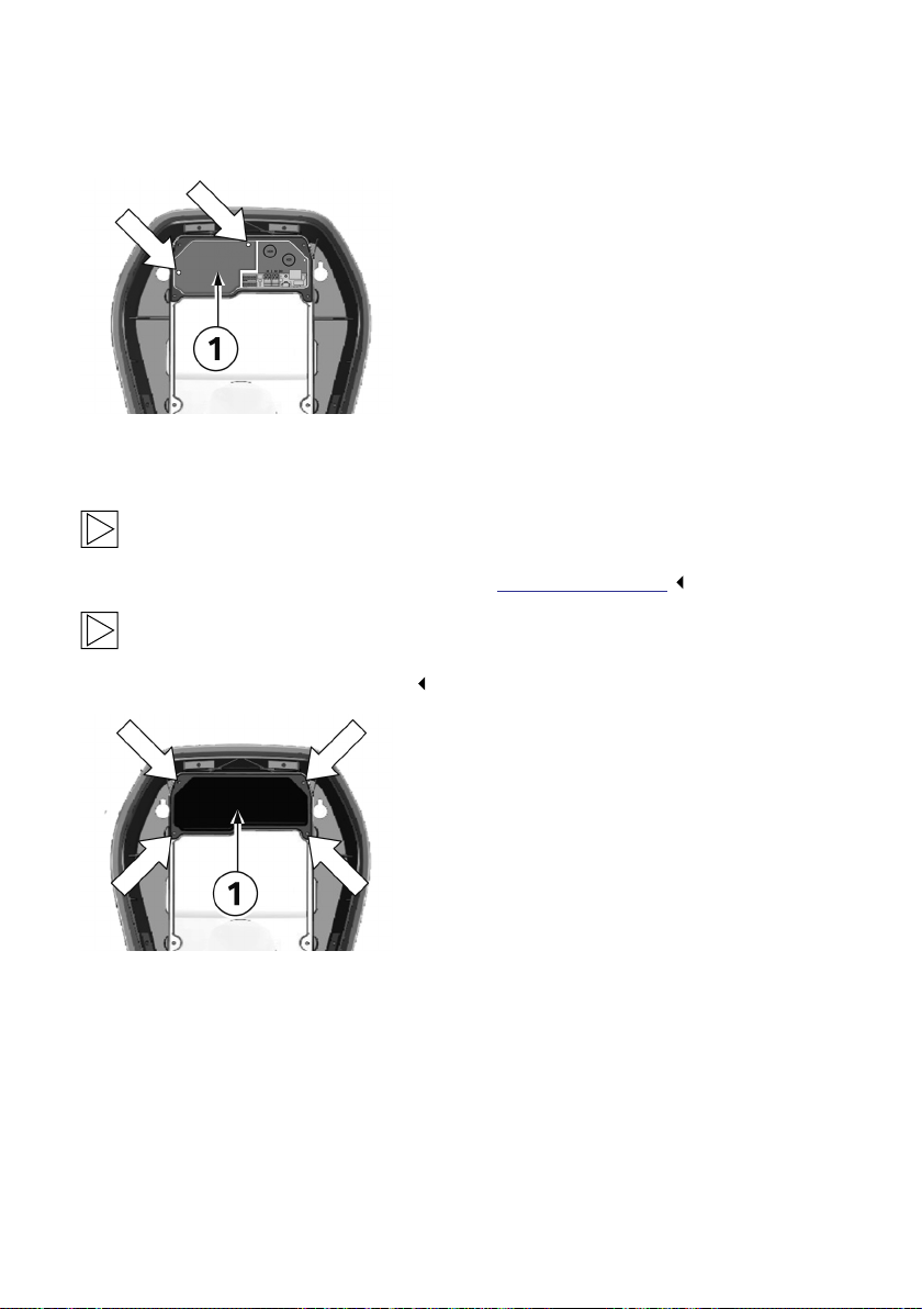
Installing the terminal cover
Fastening screws
1. Install the terminal cover 1 again using the two
fastening screws if they have been removed.
Installing the termination panel cover
Note
Confirm that an up-to-date version of the software is available before you install the terminal
panel cover. For further information see section SOFTWARE UPDATE.
Note
The Wallbox must not be permanently commissioned if this cover is missing or damaged.
Alternative covers must not be used.
Fastening screws
1. Insert the termination panel cover 1 again.
2. Install the termination panel cover again using
the four screws.
46
Page 47
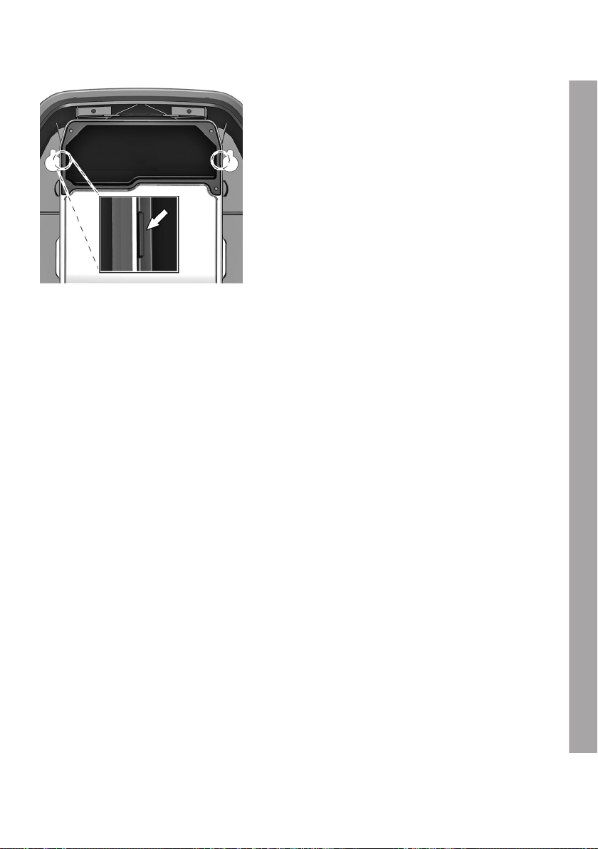
Housing marking
1. Tighten the four screws until the housing
markings on the right and left on the
termination panel cover are flush with the
housing.
2. The termination panel cover must correctly
seal the housing.
Increased force is required for the self-tapping
screws: 3.5Nm.
47
EN
Page 48
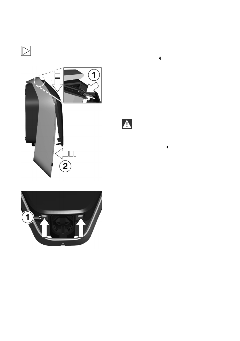
Install the housing cover
Note
This cover is not relevant for the safe operation of the Wallbox.
Attach the housing cover
1. Attach the housing cover at the top, and
2. Press the cover downwards and then swing
Locks
1. Press the bottom section of the housing cover
ensure that the hooks on the housing cover are
correctly attached 1.
the housing cover 2 backwards.
The housing cover must slide into the bottom
guides without any major resistance.
CAUTION
Make sure that the housing cover is
correctly positioned in the housing guide
on all sides. There must be only a uniform
minimum gap.
on to the Wallbox until the locks 1 fully engage.
48
Page 49
MISCELLANEOUS
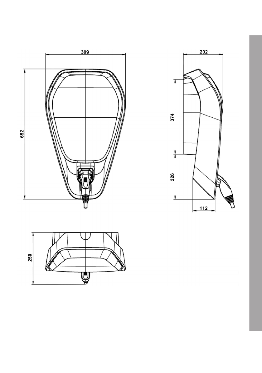
Dimensions
Dimensions in millimetres
EN
49
Page 50
Technical data
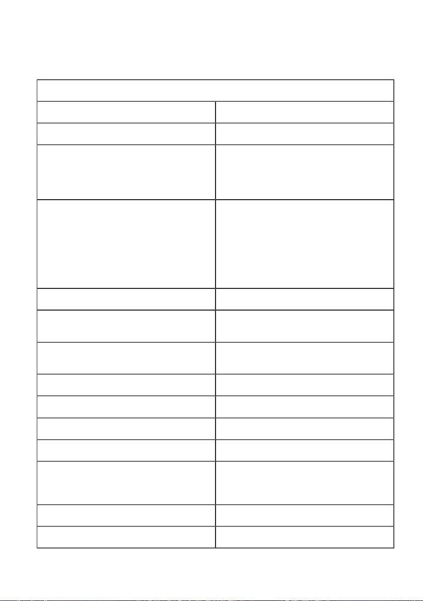
Electrical data
Charging mode: Mode 3 as per IEC 61851-1
Cable feed: Surface-mounted or flush-mounted
Connection cross-section: Minimum cross-section (depending on the cable
and type of installation):
- 5 x 2.5 mm² (16 A nominal current)
- 5 x 6.0 mm² (32 A nominal current)
Supply terminals: Connection cable:
- rigid (min.-max.): 0.2 – 16 mm²
- flexible (min.-max.): 0.2 – 16 mm²
- AWG (min.-max.): 24 – 6
- flexible (min.-max.) with wire-end ferrule
with/without plastic sleeve:
0.25 – 10 / 0.25 – 10 mm²
Temperature rating of supply terminals: 105 °C
Rated current (configurable connection values): 10 A, 13 A, 16 A, 20 A, 25 A or 32 A
3-phase or 1-phase
Mains voltage: 220-240 V ~
220/380 - 240/415 V 3N~
Mains frequency: 50 Hz/60 Hz
Mains configuration: TT/TN/IT
Overvoltage category: III as per EN 60664
Rated short-time current resistance: < 10 kA effective value to EN 61439-1
Fuse (in the domestic installation): The fusing must comply with the local
regulations depending on the socket/cable
version (see rating plate).
DC residual current monitoring: ≤6 mADC (integral)
Ventilation during charging: Not supported
50
Page 51
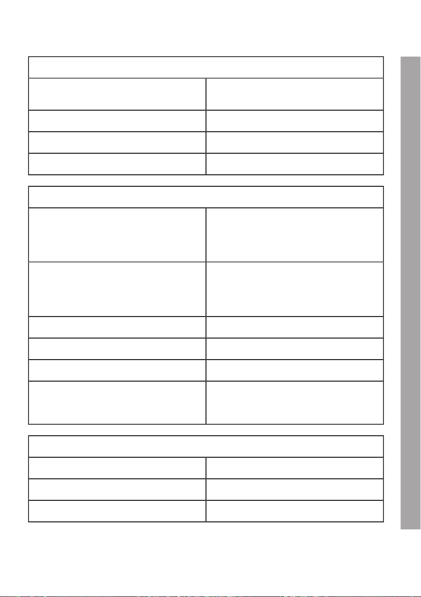
Electrical data
Version with charging socket: Type 2 standard socket with shutter: 32 A/400
VAC to EN 62196-1 and EN 62196-2
Protection class: I
Device's IP protection class: IP54
Protection against mechanical impact: IK08
Interfaces
Enable input [X1]: Enable input for external authorisation:
Connection cable:
- Cross-section (min.-max.): 0.08 – 4 mm²
- AWG (min.-max.): 28 – 12
RS485 connection [X2]: Extra-low safety voltage <50 V
Connection cable:
- Cross-section (min.-max.): 0.08 – 4 mm²
- AWG (min.-max.): 28 – 12
Diagnostic connection [X3]: RJ45
Ethernet1 connection [X4]: LSA+ terminals
USB connection [X5]: USB jack type A (max. 500 mA)
RFID (optional): MIFARE cards or tags to ISO 14443 or ISO
15693 Tag-It
or Tag-It cards or tags to ISO 15693
Mechanical data
Dimensions (W x H x D) 399 x 652 x 202 mm (without connector)
Weight: approx. 10 kg (depending on version)
Assembly (stationary): On the wall or on the column
EN
51
Page 52
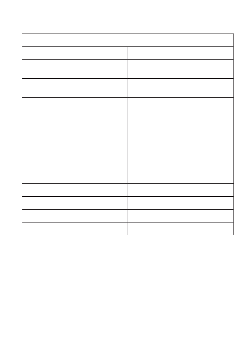
Ambient conditions
Use: Indoor and outdoor use
Operating temperature at 16 A: -25 °C to +50 °C
without direct sunlight
Operating temperature at 32 A: -25 °C to +40 °C
without direct sunlight
Temperature properties: This is not a safety device, it is just an operating
function. The specified operating temperature
range must not be exceeded.
Within the specified operating temperature
ranges the devices will provide the charging
current continuously.
In order to increase the charging availability,
the charging current level is reduced to 16 A
if the temperature is exceeded. The charging
cycle may subsequently also be shut down. The
charging cycle is continued, and the charging
current value is increased again after cooling.
Storage temperature range: -30 °C to +80 °C (-22 °F to 176 °F)
Temperature change rate: max. 0.5 °C/min (max. 32.9 °F/min)
Permitted relative humidity: 5 % to 95 %, non-condensing
Altitude: max. 2000 m above sea level
52
Page 53
MAINTENANCE
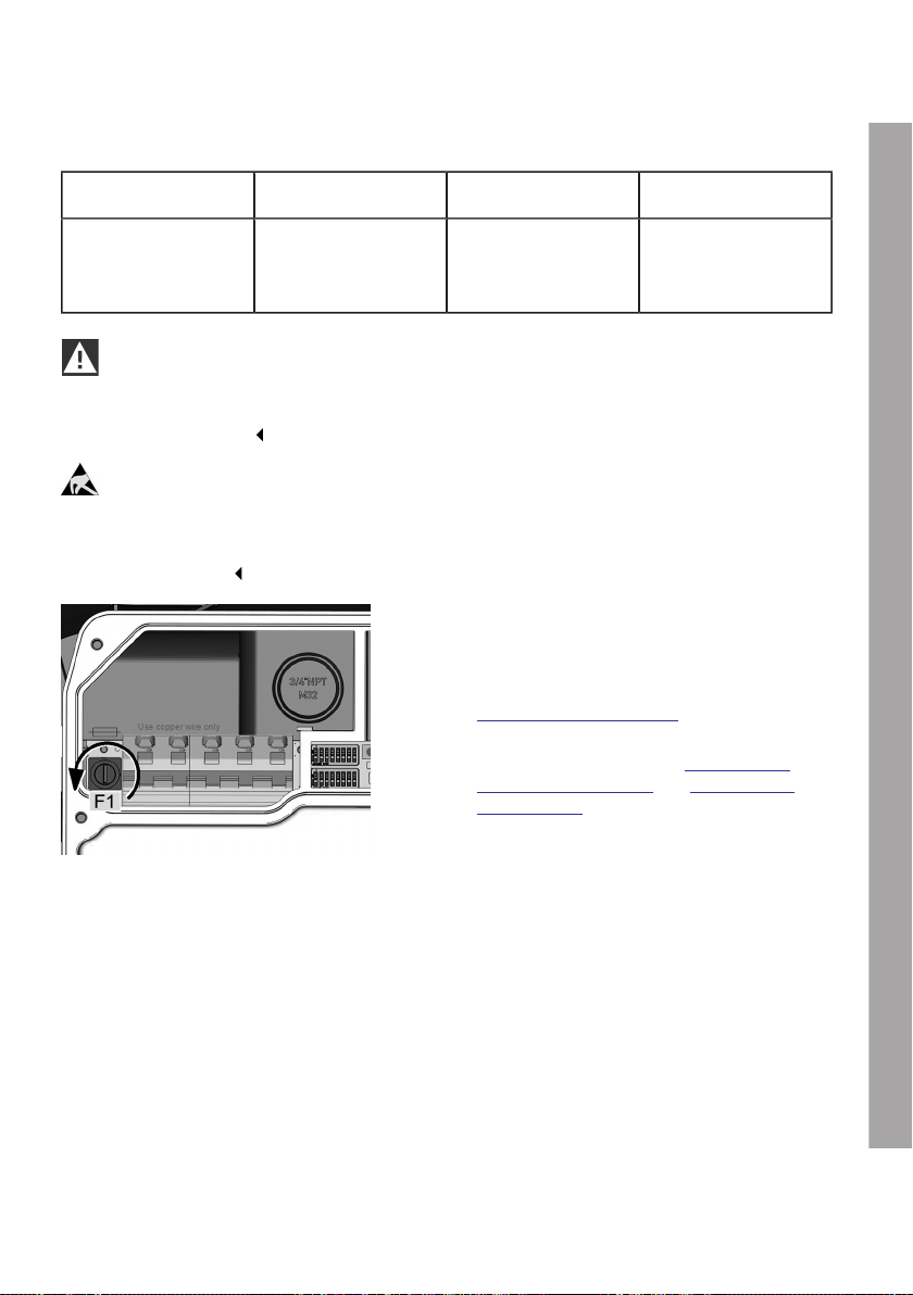
Replacing the fuse
Fuse Current/Voltage Types Dimensions
F1 6.3 A / 250 V Slow-action with high
shut-down capacity
(>1500 A) (T) (H)
WARNING
Electrical danger.
The terminal cover may only be opened by authorised electricians with the appropriate training
and qualifications.
ESD
Danger of damage. Electronic components may be destroyed if touched.
Before handling modules, perform an electrical discharge process by touching a metallic
earthed object.
Replace fuse
1. Switch off the supply cable to the Wallbox
completely.
2. Remove the housing cover, see section
Remove the housing cover.
3. Remove the terminal panel cover and terminal
cover, see sections entitled Removing the
termination panel cover and Removing the
terminal cover.
4. Press a screwdriver into the opening of the
fuse holder.
5. Turn the fuse holder anti-clockwise until it
automatically jumps forward due to the spring.
6. Replace the fuse.
7. Press the fuse holder into place and secure it
again by turning it clockwise.
8. Assemble the device again following the
instructions above in reverse order.
5 x 20 mm fuse
53
EN
Page 54

WASTE DISPOSAL
After proper decommissioning of the device, please have the device disposed of by
service or dispose of it in compliance with all currently valid disposal regulations.
Waste disposal information
The symbol of the crossed out really been means that electrical and electronic
devices and the accessories must be disposed of separately from general household
waste. Information is provided on the product, in the instructions for use or on the
packaging.
The materials can be recycled on the basis of their identifying marks. You can make
a valuable contribution to protecting our environment by reusing them, recycling the
material or other forms of reuse of end of life devices.
54
Page 55

SOFTWARE UPDATE
The software for the Wallbox can also be updated using the USB connector inside the device. The
housing cover and the terminal panel cover must be removed to gain access to the USB connector.
Follow the instructions in the manual for performing software updates.
The latest software and associated instructions can be downloaded from the
internet at https://charging.bmwgroup.com/web/wbdoc/. A new software version may,
for example, take account of changed standards or improve compatibility with new
electric or plug-in hybrid vehicles.
55
EN
Page 56

PRODUCT INFORMATION PAGE
This telecommunications equipment complies with the NTC requirement.
56
Page 57

INDEX
A
About this manual......................................................................................................................................................... 11
C
Cable inlet from above................................................................................................................................................ 24
Cable inlet from the rear............................................................................................................................................. 25
Circuit breaker................................................................................................................................................................ 15
Commissioning.............................................................................................................................................................. 44
Commissioning mode/self-test................................................................................................................................. 44
Connection diagram with open termination panel cover................................................................................... 31
Connect the supply cable.......................................................................................................................................... 32
D
DIP switch settings....................................................................................................................................................... 39
Disposal............................................................................................................................................................................ 54
E
Enable input [X1].......................................................................................................................................................... 35
Ethernet1 connection X4........................................................................................................................................... 37
F
Fuse.................................................................................................................................................................................. 53
G
General criteria for selecting an installation site................................................................................................... 14
I
Inserting additional cables.......................................................................................................................................... 29
Insert the supply cable................................................................................................................................................ 29
Installation................................................................................................................................................................ 12, 19
Installation requirements............................................................................................................................................. 19
Installing the terminal cover....................................................................................................................................... 46
Install the housing cover............................................................................................................................................. 48
Install the termination panel cover........................................................................................................................... 46
Intended use.................................................................................................................................................................. 11
L
Legal information............................................................................................................................................................. 7
M
Mains isolation device................................................................................................................................................. 15
MINI Wallbox Plus overview....................................................................................................................................... 13
Modbus............................................................................................................................................................................ 36
57
EN
Page 58

Mounting the Wallbox.......................................................................................................................................... 27, 30
P
Package............................................................................................................................................................................ 12
Prepare cable inlet........................................................................................................................................................ 26
Program RFID cards..................................................................................................................................................... 45
R
Recommended installation positions...................................................................................................................... 20
Remove the housing cover........................................................................................................................................ 22
Remove the terminal cover........................................................................................................................................ 24
Remove the termination panel cover...................................................................................................................... 23
Required distance......................................................................................................................................................... 21
Residual-current-operated circuit breaker.............................................................................................................. 15
RS485.............................................................................................................................................................................. 36
S
Safety instructions........................................................................................................................................................... 9
Safety tests..................................................................................................................................................................... 45
Supply cable................................................................................................................................................................... 15
T
Technical data................................................................................................................................................................ 50
Tool list............................................................................................................................................................................. 19
U
Use of the supply terminals....................................................................................................................................... 33
58
Page 59
Page 60
Page 61

Page 62

Page 63

Page 64

Mehr über BMW
www.bmw.de
www.bmw.com
Freude am Fahren
Doc #108154 - Mat #108154
IA MINI Wallbox Plus 1.0
 Loading...