


Installation Instructions
Z-Gate Shifter
Part Number 80681
©1998, 2001, & 2014 by B&M Racing and Performance Products
The B&M Z-Gate shifter can be used in vehicles equipped with most popular three speed automatic transmissions. YourB&MZ-Gateshiftercomesequipped with a neutral safety switch, transmission brackets and levers and a five foot shift cable. Optional shifter cables in 2 ft. (#80830), 3 ft. (#80831), 4 ft. (#80832), 8 ft. (#80834), 10 ft. (#80835) and 12 ft. (#80836) are also available. To use the B&M Z-Gate shifter with the Ford AOD transmission you will need our optional accessory kit #40496. See the list on page 8.
Please read the instructions and review the illustrations thoroughly before beginning the installation.
The mechanical components of this shifter are precision made and assembled at our factory. Any modification or disassembly of these parts can cause the shifter to malfunction and will void the warranty. You should disassemble only those items outlined in the instructions.
The vehicle should be about 2 feet off the ground for ease of installation. Use jack stands, wheel ramps or a vehicle lift. Make sure the vehicle is firmly supported before attempting to work on it. IMPORTANT: If your vehicle is equipped with a locking steering column. Securing the column lock lever in the engine compartment in the full up position will allow the steering wheel to be locked and unlocked and the ignition key to be removed.
WARNING: This allows the steering wheel to be locked WHENEVER the ignition key is turned to the “lock” position WHILE THE VEHICLE IS MOVING, OR
ATANYOTHERTIME.Securingthesteering column lock lever in any other position will both PREVENT the steering wheel from locking and the removal of the ignition key.
INSTALLATION
STEP 1. Remove the stock shift linkage; Column Shifters: Remove all rods, levers or cables from the column and the transmission. Place the column shift lever in the Park position. Remove the pin holding the shift lever in the column and remove the lever assembly. If your vehicle is equipped with a locking steering column, secure the column lock lever in the full up position. WARNING:This allows the steering wheel to be locked and ignition key removed WHENEVER the ignition key is turned to the “lock” position WHILE THE VEHICLE IS MOVING, OR AT ANY OTHER TIME.
Console Shifters: Remove the shifter mechanism from the console. Disconnect the rod or cable from the transmission. Remove the cable bracket if equipped. If there is a cable or linkage from the console shifter or the transmission to the steering column lock, it must be blocked in the Park position as described above.
NOTE: The shifter installation may require console modification or complete console removal depending on the space available in your vehicle.
STEP 2. Pull the carpet away from the floorboard where the shifter is to be mounted. If the vehicle has a bench type seat, move seat to the full forward position. Place the shifter on the floor with the
stick shifted to the rearmost position. Locate the shifter for ease and convenience of operation. Make sure the trigger and the knob clear the dash with the shifter in the Park position. Mark the position of four mounting holes on the floor.
STEP 3. Drill four 9/32" mounting holes where marked. Temporarily mount the shifter in place using washers as required to get it level. Mark the location for the shifter cable hole, 3-3/4" ahead of the front shifter mounting hole. Drill or cut a 1" diameter cable hole in the floorboard. NOTE: Some floorboards are extremely thin and will not adequately support the shifter mechanism when bolted to the floor. For those vehicles we recommend that you fabricate a stiffener plate for additional strength.
STEP 4. Install (but do not secure) the carpet back to it’s original position. Cut holes in the carpet for the mounting holes and the cable. DO NOT use a drill bit to make the holes in the carpet.
STEP 5. (This step is omitted on 1969 and later Chrysler vehicles.) Assemble the neutral safety switch and the backup light switch to the shifter using two #4-40 screws, nuts and lock washers, as shown in Figure #1. The backup light switch is on the other side of the backing plate and is not seen in the illustration. Beware, over tightening the switch attachment screws will crack the switch housings. Install the switch assembly on the shifter. To adjust the switch loosen the screws and slide the switches as required, then retighten the screws.
STEP 6. Install the cable on the shifter as shown in Figure #1. The cable attach-
Printed in the U.S.A. |
9500083-11 |
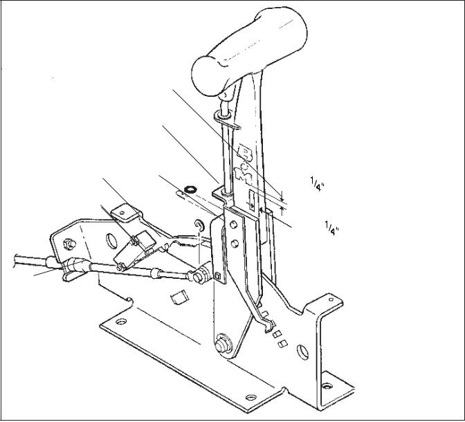
Gear indicator decal
Small O-Ring
Spring clip
Backup light switch, |
E-Clip |
|
on other side |
||
|
||
Neutral safety |
|
|
switch |
|
Cable mounting tab goes on front side of shifter backing plate
Figure #1
ment tab should be bolted to the outside surface of the shifter base using a 1/4" X 1/2" hex bolt, lock washer and nut. Install the e-clip to secure the cable to the cable pin.
STEP 7. Install the shifter mechanism into the vehicle. Slide the shifter cable through the carpet and the hole in the floor. Bolt the shifter down using four 1/ 4" hex bolts and nuts. If required use 1/ 4" washers as shims between the shifter mechanism and the floor to level the shifter. ROUTETHECABLEASSHOWN
IN FIGURE #2, AVOID SHARP BENDS WHICHWILLKINKANDDAMAGETHE CABLE. Use cable clamps or tie wraps to secure the cable housing to chassis to avoid contact with hot engine or exhaust system. For General Motors ve-
hicles go to Step 8, for Ford vehicles go to Step 13, for Chrysler vehicles go to
Step 19.
GENERALMOTORS
STEP 8. If you have not already done so, remove the stock selector lever nut and the selector lever. Discard the stock lever and the stock shifter linkage. Install the B&M selector lever in position using the stock selector lever nut (See Figure #3). Torque the nut to 23 ft. lbs. The lever should move smoothly from front to rear with a positive click in each gear position.
STEP 9. Remove the two transmission oil pan bolts from the middle of the left side of the oil pan. Install the cable bracket
in position (See Figure #3). The bracket must be installed with two spacers between the pan and the bracket. (If your transmission is equipped with a cast aluminum oil pan, these spacers should be omitted however the cable bracket will have to be modified.) Install the two 5/16-18 x 1.00" bolts supplied and tighten to 12-13 ft. lbs. Do not overtighten as this can damage the pan gasket.
STEP 10. Remove the two rubber boots, one large nut, and a large lockwasher from the threaded end of the shifter cable. Route the shifter cable according to Figure #2. Avoid sharp bends and route the cable away from hot engine exhaust parts. Slide the end of the cable into the cable bracket, install the lockwasher and large nut over the end of the cable. Posi-
2

tion the cable so the threaded portion of the cable housing is centered in the cable bracket. Tighten both large nuts to hold the cable in this position. Install the two rubber boots onto the end of the cable.
STEP 11. Move the transmission selector lever by hand to full rear position (Low). Operate the shifter lever to the Low gear position (ratcheted all the way back). Adjust the large nuts on the cable so that the swivel will slide into the center hole on the selector lever. Tighten the large nuts completely. Be sure that the swivel will slide freely in and out of the hole in the selector lever. Note: The shifter will not operate correctly unless the center hole in the shift lever is used.
Leave the swivel out of the hole and move the selector lever to Park, all the way forward. Also move the shifter to the Park position (all the way forward). Reinsert the swivel into the center hole in the selector lever. Check to see that the swivel will slide freely in and out of the center hole in the selector lever in this position. If it does not slip in freely, adjust the swivel slightly until it will slip into the hole in the lever.
Move the shifter back to the Low gear position and check that the swivel will still slide easily in and out of the center hole in the selector lever. (If you do not use the center hole in the lever, it will be impossible to correctly adjust the cable.) Operate the shifter through all the gear
Figure #2
positions. Check to make sure swivel will slide in and out of the center selector lever hole in each gear position. The shift cable is now correctly adjusted. Install the cotter key supplied with the shifter into the swivel and spread the key ends.
If you have a problem, DO NOT FORCE THE SHIFTER, this will damage the cable, the shifter or the transmission. Simply start at the beginning and check all your steps.
STEP 12. On GM vehicles the neutral safety switch may be located on the shifter (steering column or console), or it may be a mechanical interlock in the steering column that prevents the key from turning to the Start position unless the shifter is in the Park or Neutral position. Identify the type of neutral safety system you have. If the key will not turn to the Start position unless the stock shifter is in Park or Neutral, you have a mechanical interlock, otherwise you have a
GM cable bracket
Spacer
Use these two holes for
TH-400 transmission. Use
F C  R
R
Cable swivel |
GM lever |
|
|
||
Cotter pin |
|
5/16 x 1" bolt and spacer |
7/16" nut |
GM cable bracket (Trimming of bracket |
|
(Use center |
hole) |
||||
(Metric trans use M8 x 25 bolt) |
|
required if used on cast aluminum pan) |
|||
|
|
|
|||
Figure #3
3
 Loading...