


Installation Instructions
Shift Plus 2 TCU
for 4L60E, 4L65E, 4L70E, 4L80E and 4L85E
Part Number 120001
©2011 by B&M Racing and Performance Products
Thank you for purchasing the B&M Shift Plus 2 Transmission Controller Unit (TCU).The Shift Plus 2 TCU allows users to adjust nearly any aspect of a transmissions behavior for street/strip use. No software, laptop computer or tuning experience is required. This kit provides tuning right out of the box. Simply install this new transmission control unit according to the enclosed instructions, and then start the system by answering the simple setup wizard questions on the included hand-held unit.Read the instructions and review the illustrations thoroughly before beginning the installation.
|
PARTS |
Wiring |
|
Handheld user |
Transmission Control Unit |
||
Harness |
|||
Interface |
(TCU) |
||
|
|||
|
|
|
RPM Module |
Communications Cable |
Power Cable |
|
|
|
Manual Shifter Connector
Printed in the U.S.A. |
9500858-00 |

TCU - IMPORTANT!:
The TCU is water tight when connected to the wiring harness. It can be mounted in the engine compartment or in the vehicle’s interior. It is good practice to mount the TCU with the connector facing down. This way, there is less chance of moisture getting into the TCU if it needs to be disconnected in wet conditions.
The TCU should not be mounted close to other electrically “noisy” components. In particular, keep good spacing (try for 2 feet minimum) from ignition components (ignition boxes, coils, distributors, etc.)
If mounting the TCU in the engine compartment, selecting a location towards the rear will make it easier to route the communications cable to the interior to allow the handheld user interface to be monitored while driving.
There is an LED on the front face of the TCU (the side with the logo). It will flash if the on-board diagnostics detects a problem (the LED is lit solid when the TCU is powered up and working normally). To take advantage of this feature, the TCU will need to be mounted so that the front face of the TCU is visible. The handheld user interface will also indicate if any faults have been detected.
WIRING HARNESSIMPORTANT!:
The wiring harness should be kept away from ignition components (ignition boxes, coils, distributors, etc.) as much as possible. Do not bundle the wiring harness together with other “noisy” wiring in the vehicle.
As with any wiring, it is good practice to avoid routing the wiring harness around sharp edges or near high temperature components such as headers or exhaust components.
WIRING HARNESS CONSISTS OF THE FOLLOWING CONNECTION:
BATTERY POSITIVE (red wire) / NEGATIVE (black wire)
These must be connected DIRECTLY to the positive (red wire) and negative (black wire) posts of the battery. These must be run independently to the battery. DO NOT splice other power or ground wires into these wires. Failure to follow these requirements invites problems with electrical noise. These kinds of problems are difficult to diagnose. The wires may be extended if needed using automotive grade 16 gauge (or larger) wire.
12V SWITCHED (pink wire)
Connect this wire to a switched ignition source that is hot with the key in the On/Run and Crank positions. DO NOT connect to the positive side of an ignition coil. Strange problems can sometimes arise when tapping into existing switched ignition sources. When in doubt, run this wire through its own switch and then directly to the positive post of the battery.
TRANS
This connects to the round connector on the passenger side of a 4L60E transmission or on the driver side of 4L80E. Note: Pre-1993 4L80E's will need an updated internal wiring harness.B&M part# 120003, GM part# 24200161 or
equivalent.
|
|
|
4L60E |
|
4L80E |
2

OUTPUT SHAFT SPEED
This connects to a speed sensor at the rear of the transmission. In the case of the 4L80E transmissions, use the rear most sensor.
THROTTLE / TPS SIGNAL
The THROTTLE connector can be plugged into an early style GM TPS sensor. Wiring adapters are available from FAST™ ( fuelairspark.com) to accommodate a later style GM TPS (round, 3 pin connector). The harness can also be modified for use with any 0-5V TPS.
Original |
|
|
|
Pin Location |
Color |
|
Function |
A |
Black/Pink |
Ground |
|
B |
White/Red |
TPS signal |
|
C |
Red/White |
5V |
|
The loose TPS SIGNAL wire is provided to facilitate sharing the TPS signal between two systems (TCU and a fuel injection system, for example) if needed. It splits off from the THROTTLE connector’s signal wire inside the harness.
Remote mount TPS kits are available from B&M to provide a TPS signal for carbureted applications (part # 120002) . When installing one, adjust the linkage so that there is some preload on the sensor when the throttle is closed. Also adjust it so that opening the throttle all the way causes the sensor to sweep through a majority of its range - but without the sensor reaching its mechanical limit. Allowing the sensor to operate at its mechanical limits (high or low) can lead to premature failure. It will cause a TPS error code to be set if the signal voltage goes above or below approximately 4.9V or 0.1V respectively. If needed, the signal voltage can be measured on the TPS SIGNAL wire.
TACH IN / RPM MODULE
The wire with the female terminal can go from the tach output from an ignition box, other RPM signal source or to the Shift Plus 2 RPM Module depending on the application. See RPM Module notes. DO NOT connect this directly to the ignition coil.
A second wire is provided to facilitate sharing the tach signal between two systems (TCU and a fuel injection system, for example) if needed. The terminal on the second wire is the opposite gender. So something that would normally connect to an ignition box tach output or the Shift Plus 2 RPM Module can instead be plugged into this second wire in the TCU harness for a splice-free hook up.
MANUAL SHIFT
This connector contains the wires needed to enable and use manual bump up/bump down shifting. Buttons can be mounted where ever they are convenient in the vehicle – on the steering wheel, on the shift lever, etc.
Pin |
Color |
Function |
|
Notes |
A |
Red |
Bump Down |
Use momentary switch to ground to request a downshift. |
|
B |
Yellow |
Bump Up |
Use momentary switch to ground to request an upshift. |
|
C |
Blue |
Auto/Manual |
Use a toggle switch to ground to enable Manual Shifting. |
|
D |
Black |
Ground |
Can be used as the ground source for switches. |
|
SPEEDOMETER OUTPUT (orange wire)
This wire puts out a 12V square wave to drive an electronic speedometer. The number of pulses per mile is selected in the handheld user interface.
ECONOMY / PERFORMANCE (purple wire)
When switched to ground through a toggle switch, this TCU input can be used to select a more performance oriented shift strategy. Line pressure and shift points will be altered according to settings entered in the handheld user inter-
face.
3

TCC APPLY (grey wire)
When switched to ground, (and when some very basic requirements are met) this TCU input forces the torque converter clutch to lock up. Otherwise, the TCC will lock and unlock automatically based on user configurable settings.
FLASH ENABLE (blue wire)
This wire is only used in the rare case that new firmware needs to be loaded into the TCU. This wire would be grounded as the TCU is keyed on. Be sure that this wire is not accidentally grounded in normal operation. If the TCU accidentally starts up in Flash Mode (LED flashing steady on/off pattern – a slower pattern than the rapid flashing that indicates an error code has been set), the transmission will not function properly. If that occurs, make sure the FLASH ENABLE wire is not grounded, then key off, wait about 10 seconds and key back on.
HANDHELD
This connects to the communications cable that links the main wiring harness to the handheld user interface.
SPEEDOMETER CONTROL UNIT
This connects to an optional B&M Speedometer Control Unit (SCU) (part# 120004). A SCU uses an electric motor to spin a special speedometer cable to drive a mechanical speedometer.
RPM MODULE:
There are two basic options for supplying the Shift Plus 2 with an RPM input.
1. Clean, processed Tach signal from engine electronics
Electronics involved in running the engine – fuel injection, ignition, etc. – will need to know engine RPM. So there may be an existing tach signal wire that can be tapped into. The Shift Plus 2 requires a square wave type tach signal that pulses once per cylinder firing. Ignition systems – such as aftermarket capacitive discharge (CD) ignition boxes – often have dedicated “Tach” outputs that are a perfect RPM signal source for the TCU.
If using a clean, processed Tach signal, the TACH IN / RPM MODULE wire in the Shift Plus 2 wiring harness is connected directly to that source - the “Tach” output from an ignition box, etc. The RPM Module included with the kit is not used in this case and no part of the Shift Plus 2 system is connected to the coil.
2. Inductive coil
Another RPM signal source is the negative side of the ignition coil in a traditional dwell controlled inductive ignition system. One in which the coil is fed power on one side and is charged by grounding the other side - either by “points” or some form of electronic module. An HEI is one example of this type of ignition system.
To use this RPM signal option, the RPM Module is required. The RPM Module connects to the negative side of the coil and outputs a “Tach” signal to the TCU. The RPM Module is connected as follows:
Wire color |
Connection |
Black |
Engine block |
Black |
Engine block |
White |
Negative side of coil |
Yellow |
TACH IN / RPM MODULE wire in the Shift Plus 2 wiring harness |
The RPM Module is provided to allow this convenient installation option. But keep in mind that it has limitations. The negative side of an ignition coil is one of the noisiest points on the engine. In most applications, the RPM Module will be able to deal with this and feed a clean RPM signal to the TCU. But the old saying – garbage in, garbage out - applies here. If the inductive ignition system is just too noisy or inconsistent, a different RPM signal source will be needed. A poor RPM signal can cause the RPM display on the Live Data screen to appear erratic. It
can also lead to inconsistent shift points under heavy load.
4

RPM MODULE - IMPORTANT:
HEI distributors (and possibly others) have a terminal labeled “TACH”. However, this is usually not a clean, processed tach signal like many aftermarket ignition boxes would supply. Instead, it is simply another terminal connected to the negative side of the coil. DO NOT connect the TACH IN / RPM MODULE wire in the Shift Plus 2 wiring harness directly to these terminals. The TCU will be damaged. In cases like this, the supplied RPM Module
is required and will allow connection to the negative side of a dwell controlled coil.
DO NOT bypass the RPM Module and connect the TACH IN / RPM MODULE wire in the Shift Plus 2 wiring harness directly to the negative side of the coil. This may actually function for a short time but eventually the TCU will be damaged and system performance will degrade.
DO NOT connect anything from the Shift Plus 2 system to the coil – RPM Module or TACH IN / RPM MODULE wire when using an aftermarket ignition box.
Use resistor type spark plugs. Non-resistor plugs are very electrically noisy and cause interference with electronics– including the Shift Plus 2 system. DO NOT use solid core spark plug wires, these are also very noisy.
B&M Speedometer Control Unit (SCU) (Not include in kit):
An optional B&M SCU is available, part# 120004. It uses an electric motor to spin a special speedometer cable to drive a mechanical speedometer. The SCU wiring mates directly to the Shift Plus 2 wiring harness.
To configure the SCU for use with the Shift Plus 2, remove the SCU's lid to access a row of DIP switches. Set switches 4,5 and 8 to the "ON" position. All others should be "OFF". Once the switches are set, the lid can be replaced. In the setup wizard or in the advanced options menu, set the SPEEDO PPM to "4000PPM OR SCU".
In other applications, the SCU needs the DIP switches to be set according to a formula based on various drive train information. The calculation is not required for use with the Shift Plus 2. Once the switches are set as described above, the Shift Plus 2 handles the rest.It sends a calibrated speed signal to the SCU.
Installation
This is a general outline of the installation process. Read all of the component specific installation instructions for more detail before beginning the installation.
1.Connect the TRANS and OUTPUT SHAFT SPEED connectors from the wiring harness to the transmission. Route the rest of the harness into the engine compartment.
2.Determine the appropriate method for getting an RPM signal into the TCU. Install RPM Module if needed.
3.Connect the wiring harness to the RPM signal source.
4.Connect the wiring harness to a TPS signal source.
If a mechanical speedometer will be used, install the optional B&M SCU and connect the wiring harness to it.
5.Find a suitable location and mount the TCU. Make sure the wiring harness will reach the mounting location.
6.Connect the BATTERY POS and BATTERY NEG wires DIRECTLY to the battery. These must be run independently to the battery. DO NOT splice other power or ground wires into these wires. Extend the wires if necessary to reach the battery. Use automotive grade 16 gauge (or larger) wire.
7.Connect the 12V SWITCHED wire to a switched ignition source (hot in On/Run and Crank). DO NOT connect to the positive side of an ignition coil.
5
8.If Manual Shifting will be used, route the MANUAL SHIFTING connector into the cockpit and wire in an enable switch and a pair of buttons for upshift and downshift.
9.To use the Forced TCC Lockup feature, route the TCC APPLY wire into the cockpit and connect it to a switch or button.
10.To access Performance Mode, route the ECONOMY/PERFORMANCE wire into the cockpit and connect it to a switch.
11.If an electronic speedometer will be used, route the SPEEDOMETER OUTPUT wire into the cockpit and connect it to the speedometer.
12.Connect the wiring harness to the TCU.
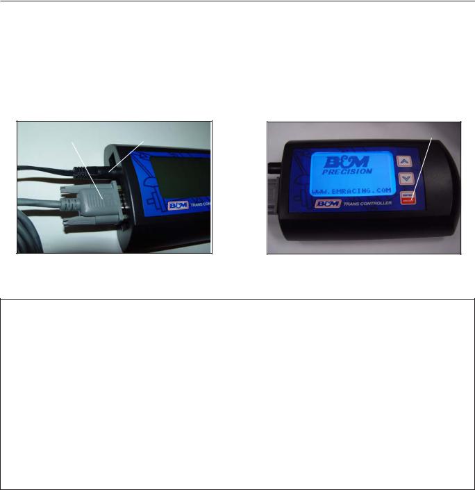
HANDHELD:
The Shift Plus 2 handheld serves as the user interface with the Shift Plus 2 system. It has a straight forward menu system that offers advanced features without requiring a laptop or any computer skills. Its first task is to take you through the Setup Wizard. It also serves as a scan tool by displaying live data and diagnostics information. Beyond basic setup, you can also adjust other settings to suit your preferences.
Communications |
Power Cable |
Power On / Off |
Cable |
HANDHELD - IMPORTANT:
The handheld has two cables that must be connected. A communications cable that links the handheld to the HANDHELD connector on the main wiring harness. And a power cable that goes to a cigarette lighter receptacle. For convenience, the handheld power source should be hot in On/Run and Crank. If it loses power while cranking, there will be a short wait before the handheld can be used as it powers back up.
The B&M Racing logo will appear once the unit is turn on. To turn off the handheld, disconnect the power cable either at the handheld itself or from the cigarette lighter receptacle. Reconnect the power cable to restart the handheld.
If the handheld displays a “COMM ERROR” message, make sure the handheld’s communication cable is connected and that the TCU is powered on. Reset the handheld.
If monitoring live data or making adjustments while driving is necessary. Be safe by bringing a friend along to operate the handheld while driving.
6
 Loading...