


Installation Instructions
Unimatic Shifter
Universal Shifter for Automatic Transmissions
Part Number 80775
©2010, 2000 by B&M Racing & Performance Products
The B&M Unimatic is a universal shifter that will work with virtually any two, three or four speed automatic transmission. It differs from other universal shifters in that it uses a cable to connect the shifter to the transmission rather than a solid rod. This allows you to locate the shifter almost anywhere on the floor of the vehicle. The B&M Unimatic also incorporates a neutral safety switch so that you cannot accidentally start the vehicle in gear. An additional safety feature requires that the shifter stick must be pushed down lightly to shift into Reverse or Park.
Cable brackets and levers are included for most popular automatic transmissions. However to install this shifter on a Ford AOD transmission you will need B&M installation kit #40496. To install this shifter on a 4L60E or 4L65E equipped with a PRNDL switch you will need B&M installation kit #75498, otherwise use supplied GM bracket.
The installation of this shifter can be handled by anyone with a minimum of mechanical experience and basic hand tools. It is important to follow the instructions. Read each step and if you do not understand it, go back and read it again.
Before beginning your installation, check the parts list at the end of these instructions to see that all of the necessary parts have been included in your kit. If anything is missing, see your B&M dealer.
Also check the tool requirement list to make sure you have all the necessary tools and supplies before starting your installation.
INSTALLATION
The vehicle should be off the ground for ease of installation. Jack stands, wheel ramps or a hoist will work fine. Do not use a jack alone. Make sure the vehicle is firmly supported.
STEP 1. Remove the stock shift linkage;
Column Shifters: Remove all rods, levers or cables from the column and the transmission. Place the column shift lever in the Park position. Remove the pin holding the shift lever in the column and remove the lever assembly. If your vehicle is equipped with a locking steering column, secure the column lock lever in the full up position. WARNING: This allows the steering wheel to be locked and the ignition key removed WHENEVER the ignition key is turned to the “lock” position WHILE THE VEHICLE IS MOVING, OR AT ANY OTHER TIME.
Console Shifters: Remove the shifter mechanism from the console. Disconnect the rod or the cable from the transmission. Remove the cable bracket if equipped. If there is a cable or linkage from the console shifter or the transmission to the steering column lock, it must be blocked in the Park position as described above.
NOTE: Shifter installation may require
console modification or complete console removal depending on the space available in your vehicle.
STEP 2. Determine where you want to locate the shifter in your vehicle. It should be a place where the floor is flat, either in the center of the tunnel or on the floor next to the tunnel. Look under the car to be sure that the area is clear of frame members or exhaust systems where you will mount the shifter. Since the cable comes out the rear of the shifter there should be no obstruction for 8" behind the selected shifter mounting location. There should also be 2.5" clearance below the floor for shifter and cable clearance. Punch a small hole in the floor where the shifter stick will be located.
STEP 3. Cut the template out of the instruction booklet and place it on the carpet. Locate the X on the template over the hole you punched in the floor. Mark the outline of the cutout area on the carpet. Remove the carpet. Mark the cut out area on the floor. With a center punch mark the locations of the four mounting bolts. Cut out the center area and drill four 9/32" holes at the center punch marks.
STEP 4. Install the shifter through the hole in the floor from the top. The cable bracket points towards the rear of the vehicle. Secure the shifter to the floor with four 1/4-20 x 1-1/2" bolts, washers, lockwasher and nuts. If the shifter does not sit flat on the floor, put extra washers between the shifter and the floor as spacers. Tighten the
Printed in U.S.A. |
9500369-09 |

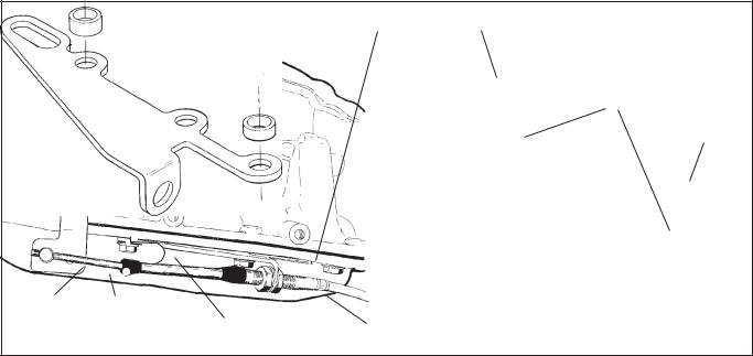
E-Clip
Slot in backing plate
FRONT
Cable "eye"
Locking nut
Figure 1
Cable route for GM and
Ford installations
Cable route for
Chrysler installations
Large wide loops provide freer shifting and longer cable life
Cable loops around to the back of the shifter
Figure 2
four bolts.
STEP 5. Check the operation of the neutral safety switch. (This step is not necessary on Chrysler transmissions.) The switch should be on when the shifter is in the Park position (with the shifter handle all the way forward) and in the Neutral position (two positions behind Park). The switch should be off in all other positions. This can be checked with a test light or an ohm meter, or you can probably hear the switch clicking when shifting from Park to Reverse, from Reverse to Neutral and from Neutral to Drive. If the switch is not operating correctly:
1. Watch to see that the switch oper-
ating lever moves up and down as the shifter is moved through the gears. The lever should move up in Park and Neutral and be down in the other gears. If the lever does not move, put a little oil on the pivot.
2.If when the lever does move, and does not turn the switch on and off, loosen the two screws holding the switch to the shifter by about a half a turn, just enough to move the switch. Move the switch up or down until it operates correctly and then retighten the screws. Do not loosen these screws too much, or the nut plate on the back side may fall off.
STEP 6. Attach the cable to the shifter. The end of the cable with the small fixed hex and the large nut attaches to the shifter. Loosen the locking nut on this end of the cable sheath and slide the cable into the slot on the shifter backing plate (See Figure 1). Put the “eye” over the cable pin. Tighten the locking nut on the cable to 10 lbft. Do not overtighten. Use the supplied e-clip to hold the “eye” in place. STEP 7. Check that the shifter moves through all the gear positions and that the other end of the cable moves in and out. Route the cable to the transmission as shown in Figure 2 to avoid sharp bends or damage to the cable. For GM and Ford transmissions route the cable to the transmission from the rear. For Chrysler transmissions the cable must be looped around to the front side of the transmission.
GM vehicles: Go to Step 8 Ford vehicles: Go to Step 13
Chrysler vehicles: Go to Step 19
GENERAL MOTORS
STEP 8. If you have not already done so, remove the stock selector lever nut and the selector lever. Discard the stock lever and the stock shifter linkage. Install the B&M selector lever in position. Install the stock selector lever nut and tighten securely (See Figure 3). The lever must be installed so it can travel its full arc equally in both directions across the center. If the lever is
2
GM cable bracket Spacer
Use these two holes for TH-400transmission.Use other two holes for other GM transmissions
Spacer
F C  R
R
Cableswivel GMlever |
|
GM cable bracket (Trimming of bracket |
|
Cotter pin |
5/16 x 1" bolt and spacer |
7/16" nut |
required if used on cast aluminum pan) |
(Use front hole) |
(Metric trans use M8 x 25 bolt) |
|
|
|
|
||
Figure 3
installed backwards, the swivel will hit the oil pan during the rearward travel arc. The lever should travel smoothly from front to back with a positive click in each gear position.
STEP 9. Remove the two transmission oil pan bolts from the middle of the left side of the oil pan. Install the cable bracket in position (See Figure 3). The bracket must be installed with two spacers between the pan and the bracket. (If your transmission is equipped with a cast aluminum oil pan, these spacers should be omitted however the cable bracket may have to be modified.) Install the two 5/16"- 18 x 3/4" bolts supplied and tighten to 12-13 lb-ft. If your transmission has metric bolts install the two 8mm bolts. Do not overtighten as this can damage the pan gasket.
STEP 10. Route the shifter cable according to Figure 2. Avoid kinks and sharp bends and route the cable away from hot engine or exhaust parts. The cable may be secured up and out of the way with nylon cable ties.
Remove the two rubber boots, one large nut, and a large lockwas her from the threaded end of the shifter cable. Slide the end of the cable into the cable bracket. Install the large nut and the lockwasher loosely over the end of the cable. Install the two rubber boots onto the end of the cable. Install the swivel on the threaded end of the cable and position it in the center of the threaded portion.
STEP 11. Move the transmission selector lever by hand to full rear position (Low). For four speed automatic transmissions (TH200-4R, TH700-R4. 4L60, 4L60E, and 4L65E) move the shifter lever to the rearmost position. For three speed automatic transmissions move the shifter lever to the next to the rearmost position. Adjust the large nuts on the cable so that the swivel will slide into the front hole on the selector lever. Tighten the large nuts completely. Be sure that the swivel will slide freely in and out of the hole in the selector lever. Note: The shifter will not operate correctly unless the front hole in the shift lever is used.
Leave the swivel out of the hole and move the selector lever to Park, all the way forward. Also move the shifter to the Park position (all the way forward). Reinsert the swivel into the front hole in the selector lever. Check to see that the swivel will slide freely in and out of the front hole in the selector lever in this position. If it does not slip in freely, adjust the swivel slightly until it will slip into the hole in the lever.
Move the shifter back to the Low gear position and check that the swivel will still slide easily in and out of the front hole in the selector lever. (If you do not use the front hole in the lever, it will be impossible to correctly adjust the cable.) Operate the shifter through all the gear positions. Check to make sure the swivel will slide in and out of the front selector lever hole in each gear position. The shift cable is now
correctly adjusted. Install the cotter key supplied with the shifter into the swivel and spread the key ends.
If you have a problem, DO NOT FORCE THE SHIFTER, this will damage the cable, the shifter or the transmission. Simply start at the beginning and carefully check all your steps.
STEP 12. On GM vehicles the neutral safety switch may be located on the shifter (steering column or console), or it may be a mechanical interlock in the steering column that prevents the key from turning to the Start position unless the shifter is in the Park or Neutral position. Identify the type of neutral safety system you have. If the key will not turn to the Start position unless the stock shifter is in Park or Neutral, you have a mechanical interlock, otherwise you have a neutral safety switch. If you have a neutral safety switch, locate and identify the neutral safety wires (engine will not crank unless these wires are connected together). With either type, disconnect the battery ground cable to prevent accidental shorts. If you have a neutral safety switch, extend both wires from the GM switch to the switch on the shifter. If you have a mechanical interlock cut the wire that goes from the Start position on the ignition switch to the solenoid on the starter. This wire is usually a 10 or 12 gauge purple wire. Run wires from both ends of the cut wire to the shifter. Put slip on terminals on the ends of the lengthened wire. Crimp the termi-
3
 Loading...