


Installation Instructions
Hammer Shifter
Part No. 80885 & 80887
©2010, 2006, 2005, 2004, 1999 by B&M Racing and Performance Products
(Visit www.bmracing.com for additional products and product information)
The B&M Hammer shifter can be used in vehicles equipped with most popular three speed or four speed automatic transmissions. Your B&M Hammer comes equipped with Neutral safety and backup light switches, transmission brackets and levers and a five foot shift cable. Optional shifter cables in 2 ft. (80830), 3 ft.(80831), 4 ft.(80832), 8 ft.(80834), 10 ft.(80835) and 12 ft. (80836) are also available. To use the B&M Hammer with the Ford AOD transmissions you will need optional accessory kit #40496. To use the B&M Hammerwith a GM 4L80E or 4L85E transmission equipped with a PRNDL switch youwillneedtheoptionalaccessorykit#75498 otherwise you can use the GM bracket supplied.
To use this shifter with a GM four speed automatic transmission (TH-700R4, TH-200 4R, 4L60,4L80E or 4L85E) you will need to remove the three speed blocker bolt and nut. (See figures 1 and 3.) For the Ford AOD four speed transmission do not remove this bolt.
Please read the instructions and review the illustrations thoroughly before beginning the installation.
Themechanicalcomponentsofthisshifter are precision made and assembled at our factory. Any modification or disassembly of these parts can cause the shifter to malfunction and will void the warranty. You should disassemble only those items outlined in the instructions.
The vehicle should be about 2 feet off the groundforeaseofinstallation.Usejackstands, wheel ramps or a vehicle lift. Make sure the vehicle is firmly supported before attempting to work on it.
IMPORTANT:If your vehicle is equipped with a locking steering column, securing the column lock lever in the engine compartment in the full up position will allow the steering wheel to be locked and unlocked and the ignition key to be removed.
WARNING: This allows the steering wheel to belockedWHENEVERtheignitionkeyisturned to the “lock” position WHILE THE VEHICLE IS
Printed in the U.S.A.
MOVING,ORATANYOTHERTIME.Securing the steering column lock lever in any other positionwillbothPREVENTthesteeringwheel from locking and removal of the ignition key.
INSTALLATION
NOTE:IfyouareinstallingthisshifterwithaGM TH-700R4, TH-200 4R, 4L60, 4L80E or a 4L85E fourspeedautomatictransmissionyou must remove the bolt and nut indicated in figures 1 and 3. Removing this bolt gives the shifter four forward positions rather than three.ForFordAODfourspeedtransmissions do not remove this bolt and nut, since this transmission has only three forward positions. Also do not remove the bolt and nut for three speed automatic transmissions.
STEP1. Remove stock shift linkage; Column Shifters: Remove all rods, levers or cables from column and transmission. Place column shift lever in “Park” position. Remove pin holding shift lever in column and remove lever assembly. If your vehicle is equipped with a locking steering column, secure the columnlockleverinthefullupposition.WARNING: This allows the steering wheel to be lockedandignitionkeyremovedWHENEVER the ignition key is turned to the “lock” position WHILE THE VEHICLE IS MOVING, OR AT ANY OTHER TIME.
Console Shifters: Remove shifter mechanism from console. Disconnect rod or cable from transmission. Remove cable bracket if equipped. If there is a cable or linkage from the console shifter or transmission to the steering column lock, it must be blocked in the “Park” position as described above.
NOTE: Shifter installation may require consolemodificationorcompleteconsoleremoval depending on the space available in your vehicle.
STEP 2. Pull the carpet away from the floorboard where the shifter is to be mounted. If the vehicle has a bench type seat, move seat to the full forward position. Place the shifter on the floor with the stick shifted to the rearmost gate position. Locate the shifter for ease and
convenience of operation, See figure2.Make sure the trigger and T-handle clear the dash with the shifter in the “Park” position. Mark the position of four mounting holes on the floor. STEP 3. Drill four 9/32" mounting holes where marked. Temporarily mount the shifter in place using washers as required to get it level. Do not bend mounting brackets on bottom of shifter. Mark the location for the shifter cable hole, 3" ahead of the left front shifter mounting hole. Drill or cut 1-1/2" diameter cable hole in floorboard. NOTE: Some floorboards are extremely thin and will not adequately support the shifter mechanism when bolted to the floor. For those vehicles we recommend that you fabricate a stiffener plate for additional strength.
STEP 4. Install (but do not secure) carpet back to it’s original position. Cut holes in the carpet for the mounting holes and cable. DO NOT use a drill bit to make holes in carpet.
STEP 5. Assemble Neutral Safety and Reverse light switches to bracket using two #4- 40 x 1" screws and nuts, as shown in figure 1. Beware, Over tightening the switch attachment screws will crack the switch housings. Install Switch assembly on shifter. To adjust switches loosen screws and slide switches in or out as required, then retighten screws.
STEP 6. Install cable on shifter as shown in figure 1. The cable attachment tab should be bolted to the outside surface of the shifter base using 1/4" x 1/2" hex bolt, lock washer and nut. Install the E-Ring that secures the cable to the cable pin.
STEP 7. Before the final installation of the shifter in the vehicle, add longer wires to the indicator light (LED) and attach the indicator cable to the side of the shifter. Attach longer wires to the indicator light leads, use butt splices or solder and tape the wires. The extension wires should be color coded or marked, since they must be connected with the correct polarity. The black wire must go to ground and the red wire must go to a 12 volt positive (+) supply. The LED will not illuminate if they are connected backwards. The red
9500575-04
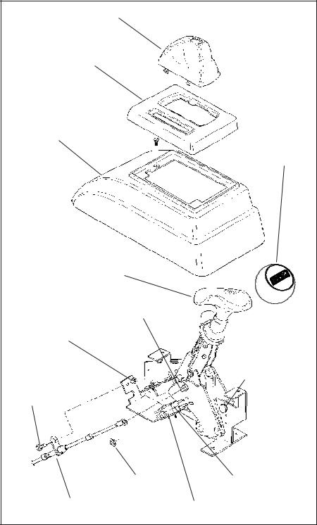
Boot
Top plate
Tower
Shifter#80885
Cable pin
1/4" nut 1/4" lockwasher
1/4" x 1/2" bolt
E-Ring
Cable attaching tab goes on outside surface of shifter base
Shifter#80887
Remove this blocker pin and the two e-clips for GM four speed transmissions
Back-up light switch
Neutral safety switch
Figure 1
wire must be connected to a source that is hot when ever the ignition is turned on, since the shifter indicator will not be visible, even in daylight, unless it is illuminated. The ground wire can usually go to one of the bolts that hold the shifter to the floor. The hot wire will probably have to go to the instrument panel.
After the wires are lengthened, slide the indicator in the shifter top plate all the way to the rear, the end away from the cable connection. Then tape the two wires to the indicator cablejustaheadofthecablemountingbracket.
Leave a little slack in these wires with the indicator all the way to the rear. About 3” further down the cable tape the wires to the cable again. See figure 4.
Secure the indicator cable bracket to the shifter mechanism with two #6 x 1/4" sheet metal screws and #6 washers. (Do not use longer screws in this position or they will cause the mechanism to bind.) The eyelet on the end of the indicator cable is secured to the cablepinbyasuppliedsmallE-Ring,asshown in figure 3.
STEP8. Install shifter mechanism into vehicle. Slide shifter cable through carpet and hole in floor. Bolt shifter down using four 1/4" x 1-1/2" hex bolts and nuts. If required use 1/ 4" washers as shims between the shifter mechanism and floor to level shifter. ROUTE
CABLE AS SHOWN IN FIGURE 5, AVOID SHARPBENDSWHICHWILLKINKANDDAMAGE CABLE. Use cable clamps or tie wraps to secure thecablehousingtochassistoavoid contact with hot engine or exhaust system. STEP9. Seal the hole where the cable goes through the floorboards to prevent air or water leakage. A putty type sealer can be used. For General Motors vehicles go to Step 10, for Ford vehicles got to Step 15, For Chrysler vehicles go to Step 21.
GENERALMOTORS
STEP10. If you have not already done so, remove the stock selector lever nut and selector lever from the transmission. Discard stock lever and stock shifter linkage. Install B&M selector lever in position using stock selector lever nut, (See figure 6). Torque nut to 23 lb. ft. The lever should move smoothly from front to rear with a positive click in each gear position.
STEP 11. Remove two transmission oil pan bolts from the middle of the left side of the oil pan. Install cable bracket in position, (See figure 6.) The bracket must be installed with two spacers between the pan and bracket. (If your transmission is equipped with a cast aluminum oil pan, these spacers should be omitted. With a TH-400 with a cast aluminum oil pan the cable bracket may have to be modified.) Install the two 5/16-18 x 1.00" bolts (Metric transmissions use the two 8mm x 25mm bolts) supplied and tighten 12-13 ft. lbs. Do not overtighten as this can damage pan gasket.
Note: In some cases possible modification to the GM cable bracket might be required for the 4L80E and 4L85E transmissions without the PRNDL switch. Verify that selector lever does not grind on cable bracket before moving on to step 10.
STEP12. Routetheshiftercableaccordingto figure 5. Avoid kinks and sharp bends and route the cable away from hot engine or exhaust parts.
Remove the two rubber boots, one large nut, and a large lockwasher from the threaded end of the shifter cable. Slide the end of the cable into the cable bracket, Install large nut and lockwasher loosely over end of cable. Install two rubber boots onto end of cable. Install the swivel on the threaded end of the cable and position it in the center of the threaded portion.
STEP 13. Move the transmission selector lever by hand to full rear position (LOW). Operate the shifter lever to the low gear position (ratcheted all the way back). Adjust the large nuts on the cable so that the swivel will slide
2

6.64 |
1.00 |
6.30 |
10.50 |
10.36 |
Trim as |
required |
Figure 2
into the front hole on the selector lever. |
position and check that the swivel will still slide |
column or console), or it may be a mechanical |
||
Tighten the large nuts completely. Be sure |
easily in and out of the front hole in the selector |
interlock in the steering column that prevents |
||
that the swivel will slide freely in and out of the |
lever. (If you do not use the front hole in the |
the key from turning to the Start position |
||
hole in the selector lever. Note: The shifter |
lever, it will be impossible to correctly adjust |
unless the shifter is in the Park or Neutral |
||
will not operate correctly unless the front |
the cable.) Operate shifter through all gear |
position. Identify the type of neutral safety |
||
hole in the shift lever is used. |
positions. Check to make sure swivel will slide |
system you have. If the key will not turn to the |
||
Leave the swivel out of the hole and move |
in and out of the front selector lever hole in |
Start position unless the stock shifter is in |
||
the selector lever to PARK, all the way for- |
each gear position. The shift cable is now |
Park or Neutral, you have a mechanical inter- |
||
ward. Also move the shifter to PARK position |
correctly adjusted. Install cotter key supplied |
lock type, otherwise you have a neutral safety |
||
(all the way forward). Reinsert the swivel into |
with shifter into swivel and spread key ends. |
switch type. If you have a neutral safety |
||
the front hole in the selector lever. Check to |
If you have a problem, DO NOT FORCE |
switch, locate the switch and identify the |
||
see that the swivel will slide freely in and out |
THE SHIFTER, this will damage the cable, |
neutral safety wires (engine will not crank |
||
of the front hole in the selector lever in this |
the shifter or the transmission. Simply start at |
unless these wires are connected together). |
||
position. If it does not slip in freely, adjust the |
the beginning and carefully check all your |
With either type, disconnect battery ground |
||
swivel slightly until it will slip into the hole in the |
steps. |
cable to prevent accidental shorts. If you have |
||
lever. |
STEP14. On GM vehicles the neutral safety |
a neutral safety switch, disconnect and ex- |
||
Move the shifter back to the low gear |
switch may be located on the shifter (steering |
tend both wires from the GM switch to the |
||
Remove this blocker pin and |
|
|
Tape wires to indicator cable |
|
the two e-clips for GM four |
|
|
close to cable bracket and |
|
|
|
|
|
|
speed transmissions |
|
|
|
|
E-Ring
Indicator
cable Adjust indicator cable bracket to
center LED indicator
Washer (2) |
|
|
|
Slide indicator all the way in this |
|
|
|
|
|
|
|
|
|
direction. Leave a little slack in wires. |
Bracket |
|
Sheet metal |
||
|
screw (2) |
|||
|
|
|||
|
Figure 3 |
|
|
Figure 4 |
|
|
|
|
|
|
|
3 |
|
|
 Loading...