

Page 1

Installation Instructions
Unimatic Shifter
Universal Shifter for Automatic Transmissions
Part Number 80775
©2010, 2000 by B&M Racing & Performance Products
The B&M Unimatic is a universal
shifter that will work with virtually any
two, three or four speed automatic
transmission. It differs from other universal shifters in that it uses a cable
to connect the shifter to the transmission rather than a solid rod. This allows you to locate the shifter almost
anywhere on the floor of the vehicle.
The B&M Unimatic also incorporates
a neutral safety switch so that you
cannot accidentally start the vehicle
in gear. An additional safety feature
requires that the shifter stick must be
pushed down lightly to shift into Reverse or Park.
Cable brackets and levers are included for most popular automatic
transmissions. However to install this
shifter on a Ford AOD transmission
you will need B&M installation kit
#40496. To install this shifter on a
4L60E or 4L65E equipped with a
PRNDL switch you will need B&M
installation kit #75498, otherwise use
supplied GM bracket.
The installation of this shifter can
be handled by anyone with a minimum of mechanical experience and
basic hand tools. It is important to
follow the instructions. Read each step
and if you do not understand it, go
back and read it again.
Before beginning your installation,
check the parts list at the end of
these instructions to see that all of
the necessary parts have been included in your kit. If anything is missing, see your B&M dealer.
Also check the tool requirement
list to make sure you have all the
necessary tools and supplies before
starting your installation.
INSTALLATION
The vehicle should be off the ground
for ease of installation. Jack stands,
wheel ramps or a hoist will work fine.
Do not use a jack alone. Make sure
the vehicle is firmly supported.
STEP 1. Remove the stock shift linkage;
Column Shifters: Remove all rods,
levers or cables from the column and
the transmission. Place the column
shift lever in the Park position. Remove the pin holding the shift lever in
the column and remove the lever assembly. If your vehicle is equipped
with a locking steering column, secure the column lock lever in the full
up position. WARNING: This allows
the steering wheel to be locked and
the ignition key removed WHENEVER
the ignition key is turned to the “lock”
position WHILE THE VEHICLE IS
MOVING, OR AT ANY OTHER TIME.
Console Shifters: Remove the shifter
mechanism from the console. Disconnect the rod or the cable from the
transmission. Remove the cable
bracket if equipped. If there is a cable
or linkage from the console shifter or
the transmission to the steering column lock, it must be blocked in the
Park position as described above.
NOTE: Shifter installation may require
console modification or complete console removal depending on the space
available in your vehicle.
STEP 2. Determine where you want
to locate the shifter in your vehicle. It
should be a place where the floor is
flat, either in the center of the tunnel
or on the floor next to the tunnel. Look
under the car to be sure that the area
is clear of frame members or exhaust
systems where you will mount the
shifter. Since the cable comes out the
rear of the shifter there should be no
obstruction for 8" behind the selected
shifter mounting location. There should
also be 2.5" clearance below the floor
for shifter and cable clearance. Punch
a small hole in the floor where the
shifter stick will be located.
STEP 3. Cut the template out of the
instruction booklet and place it on the
carpet. Locate the X on the template
over the hole you punched in the floor.
Mark the outline of the cutout area on
the carpet. Remove the carpet. Mark
the cut out area on the floor. With a
center punch mark the locations of
the four mounting bolts. Cut out the
center area and drill four 9/32" holes
at the center punch marks.
STEP 4. Install the shifter through the
hole in the floor from the top. The
cable bracket points towards the rear
of the vehicle. Secure the shifter to
the floor with four 1/4-20 x 1-1/2" bolts,
washers, lockwasher and nuts. If the
shifter does not sit flat on the floor,
put extra washers between the shifter
and the floor as spacers. Tighten the
Printed in U.S.A.
9500369-09
Page 2
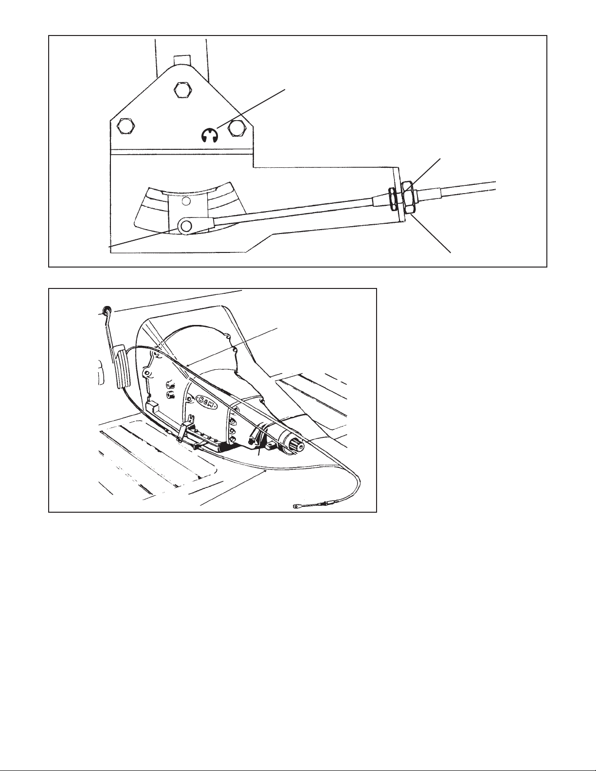
FRONT
Cable "eye"
Cable route for GM and
Ford installations
Figure 2
four bolts.
STEP 5. Check the operation of the
neutral safety switch. (This step is
not necessary on Chrysler transmissions.) The switch should be on when
the shifter is in the Park position (with
the shifter handle all the way forward)
and in the Neutral position (two positions behind Park). The switch should
be off in all other positions. This can
be checked with a test light or an ohm
meter, or you can probably hear the
switch clicking when shifting from Park
to Reverse, from Reverse to Neutral
and from Neutral to Drive. If the switch
is not operating correctly:
1. Watch to see that the switch oper-
E-Clip
Figure 1
Cable route for
Chrysler installations
Large wide loops provide
freer shifting and longer cable
life
Cable loops around to
the back of the shifter
ating lever moves up and down as
the shifter is moved through the
gears. The lever should move up in
Park and Neutral and be down in
the other gears. If the lever does
not move, put a little oil on the
pivot.
2. If when the lever does move, and
does not turn the switch on and off,
loosen the two screws holding the
switch to the shifter by about a half
a turn, just enough to move the
switch. Move the switch up or down
until it operates correctly and then
retighten the screws. Do not loosen
these screws too much, or the nut
plate on the back side may fall off.
Slot in
backing plate
Locking nut
STEP 6. Attach the cable to the
shifter. The end of the cable with the
small fixed hex and the large nut attaches to the shifter. Loosen the locking nut on this end of the cable sheath
and slide the cable into the slot on the
shifter backing plate (See Figure 1).
Put the “eye” over the cable pin. Tighten
the locking nut on the cable to 10 lbft. Do not overtighten. Use the supplied e-clip to hold the “eye” in place.
STEP 7. Check that the shifter moves
through all the gear positions and that
the other end of the cable moves in
and out. Route the cable to the transmission as shown in Figure 2 to avoid
sharp bends or damage to the cable.
For GM and Ford transmissions route
the cable to the transmission from the
rear. For Chrysler transmissions the
cable must be looped around to the
front side of the transmission.
GM vehicles: Go to Step 8
Ford vehicles: Go to Step 13
Chrysler vehicles: Go to Step 19
GENERAL MOTORS
STEP 8. If you have not already done
so, remove the stock selector lever
nut and the selector lever. Discard
the stock lever and the stock shifter
linkage. Install the B&M selector
lever in position. Install the stock
selector lever nut and tighten securely (See Figure 3). The lever
must be installed so it can travel its
full arc equally in both directions
across the center. If the lever is
2
Page 3

GM cable bracket
Spacer
Use these two holes for
TH-400 transmission. Use
other two holes for other
GM transmissions
Spacer
F
Cable swivel
Cotter pin
(Use front hole)
R
C
GM lever
5/16 x 1" bolt and spacer
(Metric trans use M8 x 25 bolt)
installed backwards, the swivel will
hit the oil pan during the rearward
travel arc. The lever should travel
smoothly from front to back with a
positive click in each gear position.
STEP 9. Remove the two transmission oil pan bolts from the middle of
the left side of the oil pan. Install the
cable bracket in position (See Figure
3). The bracket must be installed with
two spacers between the pan and the
bracket. (If your transmission is
equipped with a cast aluminum oil
pan, these spacers should be omitted
however the cable bracket may have
to be modified.) Install the two 5/16"18 x 3/4" bolts supplied and tighten to
12-13 lb-ft. If your transmission has
metric bolts install the two 8mm bolts.
Do not overtighten as this can damage the pan gasket.
STEP 10. Route the shifter cable according to Figure 2. Avoid kinks and
sharp bends and route the cable away
from hot engine or exhaust parts. The
cable may be secured up and out of the
way with nylon cable ties.
Remove the two rubber boots, one
large nut, and a large lockwas her from
the threaded end of the shifter cable.
Slide the end of the cable into the cable
bracket. Install the large nut and the
lockwasher loosely over the end of the
cable. Install the two rubber boots onto
the end of the cable. Install the swivel
on the threaded end of the cable and
position it in the center of the threaded
portion.
GM cable bracket (Trimming of bracket
7/16" nut
required if used on cast aluminum pan)
Figure 3
STEP 11. Move the transmission se-
lector lever by hand to full rear position
(Low). For four speed automatic transmissions (TH200-4R, TH700-R4. 4L60,
4L60E, and 4L65E) move the shifter
lever to the rearmost position. For three
speed automatic transmissions move
the shifter lever to the next to the
rearmost position. Adjust the large
nuts on the cable so that the swivel will
slide into the front hole on the selector
lever. Tighten the large nuts completely.
Be sure that the swivel will slide freely
in and out of the hole in the selector
lever. Note: The shifter will not op-
erate correctly unless the front hole
in the shift lever is used.
Leave the swivel out of the hole and
move the selector lever to Park, all the
way forward. Also move the shifter to
the Park position (all the way forward).
Reinsert the swivel into the front hole
in the selector lever. Check to see that
the swivel will slide freely in and out of
the front hole in the selector lever in
this position. If it does not slip in freely,
adjust the swivel slightly until it will slip
into the hole in the lever.
Move the shifter back to the Low
gear position and check that the swivel
will still slide easily in and out of the
front hole in the selector lever. (If you
do not use the front hole in the lever, it
will be impossible to correctly adjust
the cable.) Operate the shifter through
all the gear positions. Check to make
sure the swivel will slide in and out of
the front selector lever hole in each
gear position. The shift cable is now
correctly adjusted. Install the cotter
key supplied with the shifter into the
swivel and spread the key ends.
If you have a problem, DO NOT
FORCE THE SHIFTER, this will damage the cable, the shifter or the transmission. Simply start at the beginning
and carefully check all your steps.
STEP 12. On GM vehicles the neutral safety switch may be located on
the shifter (steering column or console), or it may be a mechanical interlock in the steering column that prevents the key from turning to the Start
position unless the shifter is in the
Park or Neutral position. Identify the
type of neutral safety system you have.
If the key will not turn to the Start
position unless the stock shifter is in
Park or Neutral, you have a mechanical interlock, otherwise you have a
neutral safety switch. If you have a
neutral safety switch, locate and identify the neutral safety wires (engine
will not crank unless these wires are
connected together). With either type,
disconnect the battery ground cable
to prevent accidental shorts. If you
have a neutral safety switch, extend
both wires from the GM switch to the
switch on the shifter. If you have a
mechanical interlock cut the wire that
goes from the Start position on the
ignition switch to the solenoid on the
starter. This wire is usually a 10 or 12
gauge purple wire. Run wires from
both ends of the cut wire to the shifter.
Put slip on terminals on the ends of
the lengthened wire. Crimp the termi-
3
Page 4

Ford lever
1/4 x 1-1/2" bolt, lockwasher and nut
7/16" nut
Cable swivel
C-4 cable bracket
Cotter pin
Figure 4
Remove shaded
portion of lever
nals onto the wires using a crimping
tool or pliers. Connect the wires to the
switch on the shifter. Tape the terminal connections and all other connections to prevent shorts. Reconnect the
battery ground cable, disconnect the
coil wire and set the parking brake.
Check the switch operation by attempting to start the motor in each
shifter position. The starter must
crank only when the shifter is in
the Park or Neutral position. Ad-
just the switch if required. Reconnect
the coil wire. Go to step 25.
FORD
STEP 13. If you have not already
done so, remove the nut and lockwasher holding the downshift linkage
onto the downshift lever shaft. The
downshift lever is the outer lever on C4 and C-6 transmissions. Pull the lever off the shaft and allow the linkage
to hang free. Remove and discard the
stock shift linkage rods. Some C-6,
C-5 and C-4 transmissions have a
neutral safety backup light switch on
the transmission. If your transmission
is so equipped, remove the two bolts
holding the switch in place and slide it
off the shift shaft. Disconnect the
switch at the factory plug and discard
it.
STEP 14. Install the B&M selector
lever (See Figure 4 or 5). Note: The
B&M lever must point downward for
proper operation. If the stock shift lever on your transmission points down,
you will have to remove the lower part
of the stock arm by cutting it off to
clear the B&M lever (See Figure 4).
Install the B&M selector lever onto the
shift shaft of the transmission. Align
the selector lever so when it points
straight down it travels equal arcs in
both directions from the center, then
tighten the 1/4"-20 x 1 1/2" bolt and
nut. The lever should travel smoothly
from front to back with a positive click
in each gear position. Make sure the
o-ring is in position on the downshift
shaft and install the downshift lever in
position on the shaft. Install the
lockwasher and nut and tighten securely. The downshift lever must operate smoothly. Reconnect the downshift linkage.
STEP 15. Cable bracket installation:
C-4, C-5: Remove the two lower bolts
from the rear servo cover. Install the
cable bracket in position (See Figure
4). Install the two servo cover bolts as
removed and tighten to 12-13 lb-ft. Do
not overtighten as this can distort the
servo cover.
C-6: Remove the two transmission oil
pan bolts from the left rear corner of
the oil pan. Install the cable bracket in
position (See Figure 5) with two spac-
ers between the pan and the bracket.
(If your transmission is equipped with
a cast aluminum oil pan, these spacers can be omitted.) Install the two 5/
16-18 x 1.00" bolts supplied and
tighten to 12-13 lb-ft. Do not overtighten as this can damage the pan
gasket.
STEP 16. Route the shifter cable according to Figure 2. Avoid kinks and
sharp bends and route the cable away
from hot engine or exhaust parts.
Remove the two rubber boots, one
large nut, and a large lockwasher from
the threaded end of the shifter cable.
Slide the end of the cable into the cable
bracket. Install the large nut and the
lockwasher loosely over the end of the
cable. Install the two rubber boots onto
the end of the cable. Install the swivel
on the threaded end of the cable and
position it in the center of the threaded
portion.
STEP 17. Move the transmission selector lever by hand to full rear position
(Low). Place the shifter lever to the Low
gear position, the next to the rearmost
position. Adjust the large nuts on the
cable so that the swivel will slide into
the hole on the selector lever. Tighten
the large nuts completely. Be sure that
the swivel will slide freely in and out of
the hole in the selector lever.
With the swivel in the selector lever, move the shifter to the Park position, as far forward as the shifter will go
without forcing it. (The shifter has further travel that is used to reach the GM
park position but is not used on Ford
transmissions. Trying to force the cable
will damage the cable.) The shift lever
on the transmission should be all the
way forward. Check to see that the
swivel will slide freely in and out of the
hole in the lever in this position. If it
does not slip in freely, adjust the swivel
slightly until it will slip into the hole in
the lever in both the Low and the Park
positions. Operate the shifter through
all the gear positions. Check to make
4
Page 5

sure the swivel will slide in and out of
the selector lever hole in each gear
position. Install the cotter key supplied
with the shifter into the swivel and
spread the key ends.
If you have a problem, DO NOT
FORCE THE SHIFTER, this will damage the cable, the shifter or the transmission. Simply start at the beginning
and carefully check all your steps.
IMPORTANT: Do not force the shifter
to over travel into the Park position.
This will move the shifter into GM Park
position and will damage the cable or
the transmission.
STEP 18. On Ford vehicles, the neutral safety switch is located on the
transmission or the steering column.
Locate and identify the neutral safety
wires (engine will not crank unless
these wires are connected together).
Disconnect the battery ground cable
to prevent accidental shorts. Connect
the neutral safety wires to the neutral
safety switch on the shifter. Reconnect the ground cable, disconnect the
coil wire and set the parking brake.
Check the switch operation by attempting to start the motor in each
shifter position. The starter must
crank only when the shifter is in
the Park or Neutral position. Ad-
just the switch if required. Reconnect
the coil wire. Go to step 25.
CHRYSLER
STEP 19. If you have not already
done so, loosen the pinch bolt on the
throttle lever on the transmission. This
is the lever on the small diameter
shaft. Pry the lever off with a screwdriver and allow the linkage to hang
free. Remove and discard the stock
shift lever and the stock shift linkage.
Install the B&M selector lever in position and tighten the pinch bolt securely (See Figure 6). Make sure the
lever is not pushed down so far as to
touch the transmission case. This will
cause the lever to bind on the case.
The lever should travel smoothly from
front to back with a positive click in
each gear position. Install the stock
throttle lever in position on the small
diameter shaft as removed and tighten
the pinch bolt securely. The throttle
lever must operate smoothly.
STEP 20. Remove the two transmission oil pan bolts directly below the
shift lever. Install the cable bracket in
position (See Figure 6) with two spac-
1/4" x 1-1/2" bolt,
lockwahsher, nut
Ford
lever
Cable swivel
Cotter pin
5/16" x 1" bolt
and spacer
Figure 5
ers between the pan and the bracket.
(If your transmission is equipped with
a cast aluminum oil pan these spacers can be omitted.) Install the two 5/
16-18 x 1.00" pan bolts supplied and
tighten to 12-13 lb-ft. Do not overtighten as this can damage the pan
gasket.
STEP 22. Route the shifter cable according to Figure 2. Avoid kinks and
sharp bends and route the cable away
from hot engine or exhaust parts.
Remove the two rubber boots, one
large nut, and a large lockwasher from
7/16" nut
Chrysler cable
bracket
5/16" x 1" bolt and spacer
Figure 6
5
C-6 cable
bracket
7/16" nut
the threaded end of the shifter cable.
Slide the end of the cable into the cable
bracket. Install the large nut and the
lockwasher loosely over the end of the
cable. Install the two rubber boots onto
the end of the cable. Install the swivel
on the threaded end of the cable and
position it in the center of the threaded
portion.
STEP 24. Move the transmission selector lever by hand to full forward
position (Low). Place the shifter lever
to the Low gear position, the next to
the rearmost position. Adjust the large
Chrysler lever
1/4" x 1-1/2" bolt,
lockwasher, nut
Cable swivel
Cotter pin
Page 6

nuts on the cable so that the swivel will
slide into the hole on the selector lever.
Tighten the large nuts completely. Be
sure that the swivel will slide freely in
and out of the hole in the selector lever.
With the swivel in the selector lever,
move the shifter to the Park position,
as far forward as the shifter will go
without forcing it. (The shifter has further travel that is used to reach the GM
Park position but is not used on Chrysler transmissions. Trying to force the
shifter will damage the cable.) The shift
lever on the transmission should be all
the way back. Check to see that the
swivel will slide freely in and out of the
hole in the lever in this position. If it
does not slip in freely, adjust the swivel
slightly until it will slip into the hole in
the lever in both the Low and Park
positions. Operate the shifter through
all the gear positions. Check to make
sure the swivel will slide in and out of
the selector lever hole in each gear
position. Install the cotter key supplied
with the shifter into the swivel and
spread the key ends.
If you have a problem, DO NOT
FORCE THE SHIFTER, this will damage the cable, the shifter or the transmission. Simply start at the beginning
PARTS LIST
and carefully check all your steps.
IMPORTANT: Do not force the shifter
to over travel into the Park position.
This will move the shifter into the GM
Park position and will damage the
cable or transmission.
STEP 23. Check the operation of the
throttle linkage again. The linkage must
operate smoothly with no bind. All
transmissions using automatic valve
bodies must have the throttle linkage
connected and operating, or transmission damage will result.
STEP 24. The neutral safety switch
is located on the transmission and
will continue to function normally. It
will not be necessary to hook up the
switch on the shifter. Go to step 25.
STEP 25. Remove the T-handle. Slip
the boot and the plate over the shifter
stick. Mark the positions of the hold
down screws, using the boot plate
and the template. Drill four 1/8" holes
and screw the plate and the boot down.
Put the correct shift pattern label on
the driver’s side of the boot plate.
SHIFTER OPERATION
CAUTION: The shifter is an important
controlling mechanism of your vehicle
and can create serious driving hazards when any part is loose, missing
or misadjusted. After you have installed your B&M Unimatic Shifter
we recommend you review the instructions to assure a complete and proper
installation.
The operation of the shifter is very
simple. The shifter is moved forward
or backward like the original shifter.
To shift out of Park, push down lightly
on the handle. Then pull back to any
desired gear position. To shift from
Neutral to Reverse, push down lightly
on the handle then push stick forward
to Reverse.
TOOL LIST
Phillips screwdriver
Flat screwdriver
Ratchet or speed handle
Sockets - 7/16", 1/2", 13mm,15mm
Open end wrenches - 7/16", 1/2",
9/16", 11/16"
Drill motor
Drill bits - 9/32", 1/8"
Tin snips and/or hacksaw
Crimping tool or pliers
Electrical tape
Jack stands
Cable ties (optional)
1 Shifter assembly
1 Shifter cable
1 Cable swivel
1 Boot, boot plate and
4 #10 sheet metal screws
1 GM cable bracket
1 Torqueflite selector lever
1 Torqueflite cable bracket
1 Ford selector lever
1 C-4 cable bracket
threads of the stick and make it
impossible to remove the T-handle
from the stick. If this occurs it can
cause the stick to break if you use
IMPORTANT
The T-handle may gall on the
excessive force while attempting to
1 Indicator decal
1 "T" handle and jam nut
4 1/4-20 x 1-1/2" bolts, full
thread
5 1/4-20 nuts
5 1/4" lock washers
8 1/4" flat washers
1 C-6 cable bracket
2 Cable bracket spacers
2 M8-1.25 x 25mm bolts
2 5/16-18 x .75" bolts
1 1/4-20 x 1-1/2" bolt
2 Cotter pins
2 3/16" slip-on terminals
remove the T-handle from the stick.
Before installing the T-handle onto
the stick put some Loctite® on the
threads of the stick. Loctite® will
prevent galling and secure the Thandle to the stick. If you do not use
Loctite®, put a little grease on the
threads of the stick to prevent galling.
1 GM selector lever
WARNING
PERIODIC INSPECTION AND MAINTENANCE OF YOUR SHIFTER IS RECOMMENDED TO ENSURE THAT THE
MECHANISM IS WELL LUBRICATED, FREE FROM DIRT OR RUST AND THAT THE CABLE IS PROPERLY
ADJUSTED. LACK OF MAINTENANCE COULD RESULT IN A FAILURE INCLUDING A FAILURE OF THE
REVERSE LOCKOUT SAFETY FEATURE.
6
Page 7

CUT OUT
THIS AREA
X
9/32" dia
4 places
GM cable bracket
GM lever
Template for floor cutout
C-4 cable bracket
C-6 cable bracket
Chrysler cable bracket
Chrysler lever
Ford lever
Cable brackets and levers
7
 Loading...