

Page 1

Installation Instructions
Transpak 1982-93 GM TH-700R4
(4L60) Non Electronic Transmission
Part Number 70235
©2001, 1996 by B&M Racing and Performance Products
The B&M TH-700 (4L60) Transpak
has been designed to work on all 1982
thru 1993 TH-700’s (4L60's). This kit
WILL NOT work on 1992 and later
4L60E (electronic) models. During 1982
thru 1993 model years four major
changes were made to the TH-700’s
hydraulic circuitry. It is important that
you know the year model of the transmission your working on so that you
can identify the correct checkball placement diagram. Figure 1 describes
where to look on your transmission for
model year identification. If the original
transmission in your vehicle was replaced by a factory rebuild, the I.D.
number may have been changed. In
this case you will have to compare the
components in your transmission with
the check ball placement diagrams in
the instructions to determine the correct check ball placement.
WARNING: Incorrect checkball
placement can result in serious
transmission damage. Be sure to
follow the instructions carefully.
We have included a section on TV
cable installation that will be helpful to
individuals using the TH-700 with aftermarket carburetors, manifolds or in a
custom vehicle installation.
B&M's TH-700 Transpak can be installed by anyone with minimum mechanical experience. It is however, im-
portant to closely follow the instructions.
We recommend that you read
through the instructions completely
before beginning the installation,
so you can familiarize yourself with
the installation procedure and tools
required. Check the tool list at the
end of these instructions for the
tools required to install your B&M
TH-700 Transpak.
NOTE: The B&M TH-700 Transpak is
not a cure-all for an ailing transmission. If your transmission is slipping or
in poor general shape, the installation
of this Transpak may worsen the condition. However on a properly operating
transmission in average condition, the
Transpak will provide the kind of transmission performance your looking for.
When installing your Transpak there
are several other B&M products you
may wish to consider:
TH-700 R4 KICKDOWN KIT #70237
The TH-700 has a hydraulic circuit that
causes a forced 4-3 down shift whenever the throttle is opened past two
thirds travel. In some applications a
part throttle forced 4-3 down shift is
undesirable, after many customer requests B&M has developed an easily
installed kit that will eliminate the part
throttle 4-3 down shift feature. This kit
does not alter normal shift speeds or
affect detent (wide open throttle 4-3)
operation. This kit is best installed
along with B&M’s #70235 Transpak.
However it can also be installed independent of other modifications, and
valve body removal is not required (pan
gasket not included).
Converter Lockup Control #70244/
70248 Provides electronic control of
the vehicle speed where lockup takes
place on GM transmissions with lockup
converter. Eliminates lock and unlock
cycling and premature unwanted
lockup. Also ideal for lockup operation
in vehicles that did not come with
lockup converter transmissions. Works
with all GM lockup transmissions.
TRANSMISSION OIL COOLER We
feel that it is very important that every
vehicle in addition to the radiator heat
exchanger should have an oil cooler.
Heat is the major cause of transmission failures, and an oil cooler is an
inexpensive safeguard against overheating. B&M offers a wide range of
transmission coolers to suit every need,
which are available at your B&M dealer.
The TH-700 runs hotter than most other
automatic transmissions, making an
oil cooler almost a necessity.
TRICK SHIFT PERFORMANCE ATF
Trick Shift performance automatic transmission fluid is the industry’s leading
performance ATF. A specially blended
Printed in U.S.A.
9500260-12
Page 2

oil with foam inhibitors, extreme pressure agents and shift improvers, this
fluid assures protection while delivering the fastest possible shifts. You
literally “Pour in performance.” Available at your B&M dealer.
DRAIN PLUG KIT #80250 TH-700
transmissions do not come from the
factory equipped with drain plugs. The
B&M Drain plug kit is inexpensive
and easy to install. It eliminates the
mess of a fluid change or pan removal.
POWER SWITCH KIT #80217 (1982
through 1989 TH-700’s only) This kit
will enable you to select between normal Torque Converter Clutch (TCC)
operation and having it unlocked in all
gears except fourth. This kit can also
be utilized for TCC control in custom
installations of the TH-700. Keeping
the TCC in the unlocked mode during
city driving saves wear and tear on the
TCC as well as minimizing TCC engagement at low speeds. The B&M
Power Switch Kit will not prevent the
TCC from locking in fourth gear (overdrive). TCC engagement in fourth gear
is required to prevent transmission overheating. Kit does not work on 1990 or
later TH-700’s.
TH-700 DEEP OIL PAN #70289 The
B&M TH-700 deep oil pan ads approxi-
mately 3 quarts of extra oil capacity to
your transmission. The additional oil
capacity will help reduce the temperature of your transmission, thereby promoting longer transmission life.
TEMPERATURE GAUGE KIT #80212
Most transmission and converter failures can be traced directly to excessive heat. The B&M transmission temperature gauge can save you a costly
repair bill by warning you ahead of time
of an overheated transmission. The
B&M temperature gauge is extremely
accurate and dependable, it comes
with all necessary hardware and is
easy to install.
INTRODUCTION
This kit can be installed in a few
hours by carefully following the instructions. Read all instructions first to
familiarize yourself with the parts
and procedures. Transmission com-
ponents are precision fit, work slowly
and do not force any parts. Burrs and
dirt are the number one enemies of an
Figure 1
automatic transmission. Cleanliness
is very important, so a clean work
surface from which oil can easily be
removed is necessary.
This kit contains all parts necessary to obtain two different levels of
performance, depending on intended
use:
1. Heavy Duty; Towing, campers, motor homes and 4-wheel drive vehicles.
Shift feel is firm and positive.
2. Street; Dual purpose performance
vehicles, street and strip performance
cars. Street level produces the firmest
shift feel.
DISASSEMBLY
Automatic transmissions operate
at temperatures between 150° F and
250° F. We suggest the vehicle be
allowed to cool for several hours before
disassembly to avoid burns from hot oil
and parts. Have an oil drain pan ready
to catch oil and a tray on which to put
small parts so they won’t get lost. The
vehicle should be raised so there is at
least 2 feet ground clearance for ease
of installation and safety.
MAKE SURE THE VEHICLE IS RIGIDLY AND SECURELY SUPPORTED,
JACK STANDS, WHEEL RAMPS OR
A HOIST WORK BEST, DO NOT USE
JACKS ALONE.
STEP 1. The TH-700 does not have a
drain plug. Position your drain pan
beneath the transmission to catch the
oil. Remove the oil pan by removing the
rear bolts first, then work towards the
front. Loosen but do not remove the
three front bolts. If the pan sticks to the
gasket, insert a flat screwdriver between the pan and case and pry down
gently to break the pan loose. Now
remove the front three bolts slowly to
permit draining the rest of the oil. Remove pan gasket material from the pan
and the case.
STEP 2. Remove the oil filter by gently pulling it straight down. The pickup
tube has an O-ring (or seal) around the
end that fits into the pump housing.
Sometimes the O-ring (or seal) remains in the pump bore, if so remove Oring (or seal) from the pump and discard both the O-ring ( or seal) and filter.
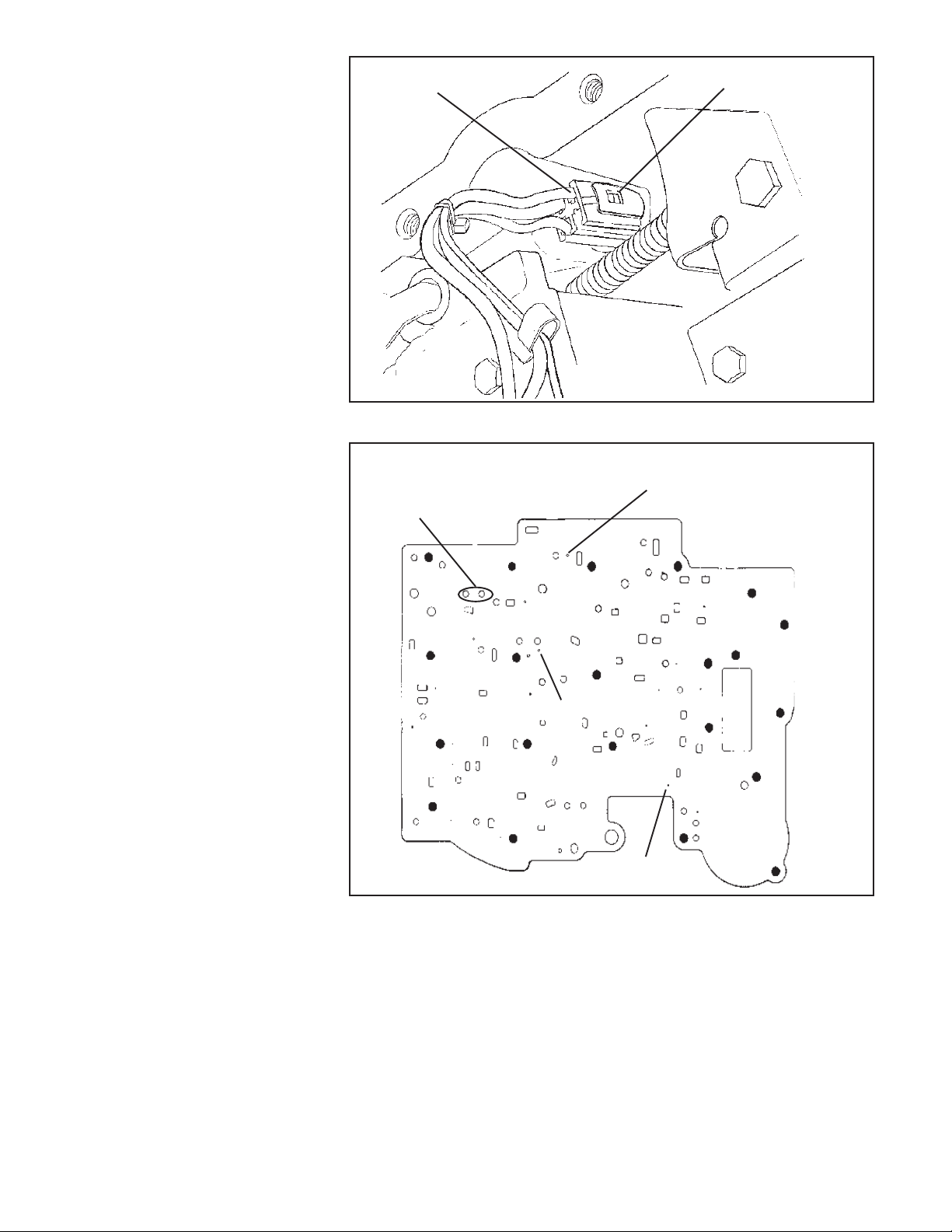
STEP 3. (See Figs. 2 and 3) There
are a variety of different wiring harnesses used on the TH-700. Before
proceeding further make a sketch and
some notes describing your particular
unit, recording which connectors go to
which switch. Notice that the connec-
2
Page 3

tors are color coded. Now remove connectors from switches. Unplug the wiring harness from the case electrical
connector by prying the lock tab away
from the plug and pulling down on the
plug, do not pull on the wires. Removing solenoid is not required, just tie
the wires up out of the way.
STEP 4. Remove all except the center valve body bolt (See Fig. 2.) Beginning with the mid 1987 model year, TH700’s have a tube crossing over the
valve body. This tube is removed by
simultaneously pulling both ends out of
their respective bores. With the tube
removed (if equipped) hold the valve
body up firmly with one hand and remove the remaining bolt slowly. There
are several check balls in the valve
body along with several pints of oil.
Have your drain pan ready to catch the
oil and check balls (should they fall
out.) Save all check balls in a safe
place where they won’t get lost.
STEP 5. Beginning mid 1987 model
year, TH-700’s have an auxiliary valve
body located where earlier models have
a cover plate (See Fig. 2.) Remove the
cover plate or auxiliary valve body. Be
careful not to drop the check ball located in the auxiliary valve body (See
Fig. 8.) Remove the 1-2 accumulator
housing while holding the separator
plate up to the case. Then slowly lower
the separator plate and retrieve the
check balls located above the plate.
Make note of the color and location of
the 1-2 and 2-3 accumulator springs for
correct reassembly (See Fig. 10.)
Remove all old gasket material from
Servo vent
Do not block
this hole
Throttle valve
linkage
Filter retaining
spring
1-2 accumulator
B
B
C
housing
Converter clutch
lockup solenoid
B
C
B
B
B
A
Crossover
tube
Selector lever
detent spring
E
F
body
B
B
B
B
B
Electrical
connector
B
B
B
B
B
C
C
Auxiliary valve
Figure 2
3
Page 4
these parts. Note: Early 1982 TH-
700’s had a support plate located
under the 1-2 accumulator housing. If your transmission is fitted with
this plate, carefully save the gasket as
you will have to re-use the gasket upon
reassembly (Gasket GM P/N 8642129
is not included in kit.)
MODIFICATIONS
STEP 6. Using the supplied drills, en-
large the holes in your separator plate
as indicated in Fig. 4. Carefully deburr
the holes after drilling.
STEP 7. Rinse off valve body with
clean solvent to remove any dirt or grit.
Move to a clean working area. The valve
body consists of precision fit components which will not tolerate dirt or
burrs.
STEP 8. Heavy Duty and Street;
MTV upshift valve (See Fig. 5.)
Remove the pin at the end of the MTV
upshift valve bore. Remove the plug,
valve and spring from the bore. Set the
spring aside (it will not be re-used.) Reinstall the valve, plug and pin in reverse
order of removal.
STEP 9. Street Only; Line bias
valve.
Compress and remove the large roll pin
retaining the line bias valve (See Fig.
5.) Take care to not distort the roll pin
more than is required to remove it.
Remove the aluminum plug, valve and
spring from bore. The spring will not be
re used. Insert the blocker rod from the
kit into the bore. Install the valve and
aluminum plug as removed. If the aluminum plug extends into the roll pin
hole, remove the blocker rod and grind
or file a small amount from either end of
the blocker rod until the aluminum plug
clears the roll pin hole when all parts
are installed.
STEP 10. Heavy Duty and Street;
Pressure regulator.
Remove the snap ring at the end of the
pressure regulator bore in the oil pump
assembly (See Fig. 6.) Use a screw-
driver to hold the pressure regulator
assembly while removing the retaining
ring. If the sleeves stick in the bore,
lightly rap the sleeve with a small rod
and a mallet. Remove two sleeves with
valves and the pressure regulator spring.
The pressure regulator valve may fall
out but it does not need to be removed.
Wiring harness plug
Figure 3
Note: additional model year I.D.
1982 thru mid-87 (2) holes
mid-1987 to 1988 (2) holes
1988 and later (1) hole
Drill 1/8" (.125")
Drill 3/32" (.094")
Figure 4
Reassemble the pressure regulator
assembly using the BLUE spring from
the kit (See Fig. 7.) Use the new
retaining ring from the kit. Make sure
the retaining ring is firmly seated in its
groove when assembled. CAUTION:
The pressure regulator valve train
MUST be installed in the proper
order with the sleeves and valves
oriented in the indicated directions.
There are several ways the sleeves and
Pry lock tab aside
to remove plug
Drill 1/8" (.125")
valves can be installed, however, only
the orientation shown will work properly. Improper installation will cause
low line pressure, resulting in slipping
clutches and burned friction elements.
It is very important to reassemble the
pressure regulator correctly to insure
proper operation of the transmission.
Take a little extra time with this step
and work slowly. This is a precision fit
valve assembly so do not force the
4
Page 5

Aluminum plug
recess should
face out
Roll pin
MTV upshift
valve
Remove
spring
Street level only, replace line
bias valve spring with blocker
rod from kit
Line bias
valve
Aluminum plug
recess should
face out
Large diameter
roll pin
Pressure
regulator bore
Figure 5
Pressure regulator valve assembly must
be installed as shown in this order
Pressure regula-
tor retaining ring
Manual valve link must
be assembled as shown
Figure 6
Figure 7
5
Page 6

Check ball position "A", 1984 1/2 and later
models have larger check ball in this position
(earlier models have nothing in position "A")
Check ball
position #4
Do not install check
ball in this position
Check ball
position #6
Check ball
position #3
Check ball
position #3
Check ball
position #2
Figure 8 - Transmission without auxiliary valve body (Before mid-1987)
Check ball position "A",
copper flashed ball larger than
other check balls
Check ball
position #1
Auxiliary valve
body
Check ball
position #5
Check ball
position #4
Do not install check
ball in this position
Do not install check
ball in this position
Check ball
position #6
Check ball
position #2
Do not install check
ball in this position
Figure 8A - Transmission with auxiliary valve body (mid-1987 to 1988)
Check ball
position #1
6
Check ball
position #5
Do not install check
ball in this position
Page 7

Check ball
position #3
Check ball
position #2
Check ball position "A",
copper flashed ball larger than
other check balls
Do not install check
ball in this position
Do not install check
ball in this position
Auxiliary valve
body
Check ball
position #1
Do not install check
ball in this position
Check ball
position #5
Check ball
position #6
Check ball
capsule
1988 and
later. Must
be in original location.
Do not install check
ball in this position
Check ball
position # 3
Check ball
position # 2
Check ball
position # 7
Figure 8B - Transmission with auxiliary valve body (1988-92)
Check ball position "A"
Copper flashed ball larger
than other check balls
Auxiliary valve
body
Check ball
position # 1
Do not install check
ball in this position
C
V
Case side
gasket
Valve body
side gasket
1993 case check balls same as Figure 8B
Figure 8C - Transmission with aux. valve body
(1993 Only)
Seperator plate gaskets
Figure 9
7
Page 8

valves back into the bore. During reassembly, you can smear grease on the
valve and spring before you insert them
into the bore to hold them in place while
you install the boost valve assembly.
To ease installation a thin blade screwdriver can be used to hold the assembly up into the bore while you install the
snap ring. Place the snap ring around
the screwdriver and slide it up into
place with the snap ring pliers. Be sure
the snap ring goes into the groove and
is not against the step in the bore.
ASSEMBLY
STEP 11. Heavy Duty and Street;
Check ball placement (See Fig’s. 8,
8a and 8b.) Place check balls in the
valve body, auxiliary valve body and
case in the positions shown. Use a dab
of grease or petroleum jelly to hold
check balls in position. Beginning mid
1984 model year TH-700’s have a check
ball which is larger than the others in
the valve body position ‘A’. If your
transmission is equipped with this
check ball replace it in position ‘A’. If
your transmission does not have this
check ball then place nothing in posi-
tion ‘A’, pre mid 1984 transmissions
were not equipped with a check ball in
this position.
STEP 12. Place the new separator
plate gaskets on the separator plate
(See Fig. 9.) Use a dab of grease or
petroleum jelly to help hold the gaskets to the plate. The gasket with the
‘C’ cut in it goes next to the case and
the gasket with the ‘V’ cut in it goes
next to the valve body. Make sure no
holes in the separator plate are cov-
ered by the gasket.
If your gaskets become damaged
anytime during the installation of the
kit, replace them. If you cannot obtain
B&M replacement gaskets then purchase OEM gaskets for your specific
year and model vehicle.
STEP 13. Heavy Duty Only; Place
the 3-4 accumulator pin in the case.
Over the pin place the RED (3/8") spacer
sleeve, accumulator piston and spring
(spring is installed at step 18.) Use a
dab of grease or petroleum jelly to hold
components in place (See Fig. 10)
Proceed to step 15.
STEP 14. Street Only; Place the 3-4
accumulator pin in the case. Over the
pin place the BLUE (3/4") spacer and
accumulator piston, using a dab of
grease or petroleum jelly to hold them
in place (See Fig. 11). Important
note: With piston and spacer installed
in bore rub a straight edge on the case
surface across the accumulator bore
and verify the piston does not extend
beyond the case surface. If the straight
edge contacts the accumulator piston,
grind or file a small amount from the
spacer until the piston clears the
straight edge. No spring is used for
Street level performance.
STEP 15. Heavy Duty Only; Remove
the spring and piston from the 1-2
accumulator housing (See Fig. 10.)
Install over the pin the YELLOW spacer,
piston (notice orientation) and spring.
Proceed to step 17.
STEP 16. Street Only; Remove the
spring and piston from the 1-2 accumulator housing (See Fig. 12.) Install
both the BLUE and the RED spacers
over the pin, then the piston (notice
orientation.) No spring is used for
Street level performance.
Figure 10 Figure 11
8
Page 9

STEP 17. With the 3-4 accumulator
components and case check balls in
place, place the separator plate / gasket assembly up to the case followed
by the 1-2 accumulator housing assembly. Carefully line up the gaskets
and install three accumulator housing
bolts, tighten ONLY finger tight (See
Fig’s. 2, 10 and 11.)
STEP 18. Install the auxiliary valve
body (with check ball in correct position) or cover plate using the appropriate screws tightened ONLY finger tight
(See Fig’s. 2 and 8.)
STEP 19. Valve body installation.
Make sure check balls are in proper
locations. Position the manual valve so
the link rod can be engaged (See Fig.
6.) The link rod must be placed into the
hole of the manual rod at a right angle,
then rotated to allow the valve to enter
the valve body bore. Do not force the
valve at any time. When the valve is
fully engaged, align the valve body and
Figure 12
case holes then install one bolt finger
tight to hold valve body in place. Engage all of the remaining bolts to finish
lining up the separator plate and gaskets (See Fig. 2.) Tighten all the valve
body, auxiliary valve body (or cover)
and accumulator bolts (except cross
over tube clamp bolts and throttle
valve linkage bolts) to 11 NM (8 Ft.
Lb.) Avoid striped threads, Do not
over tighten bolts.
STEP 20. Install the throttle valve (TV)
Figure 13
linkage onto the valve body as shown
(See Fig. 12.) Engage the cable link
with the large lever first. Hold the large
lever up and the smaller one down.
Then slip the assembly into position
aligning it with the hold down bolt holes
and engage the roll pin in the slot on the
bracket. Insert bolts and tighten to 11
NM (8 Ft. Lb.) then make sure large
lever operates freely. IMPORTANT
NOTE: The TV cable MUST be reset
before operating vehicle refer to
9
step 25.
STEP 21. Carefully insert ends of
cross over tube in their respective bores
and push in evenly until fully engaged
(See Fig. 2.) Install cross over tube
bolts and clamps and tighten to 11 NM
(8 Ft. Lb.)
Reconnect wiring harness connectors
to the terminals from which they were
removed. Refer to sketch or notes made
at Step 3. Reconnect the harness to
the case connector making sure it is
Page 10

firmly seated and locked.
STEP 22. Double check installation;
1: make sure all bolts are installed and
torqued. 2: Throttle valve linkage operates freely. 3: Wiring properly connected. 4: Regulator valve retaining
ring fully seated in groove.
Coat the filter pickup tube seal with
clean ATF then push the filter tube into
the pump bore until it is fully seated.
Install filter retainer clip so it is located
at the small depression on the top side
of filter housing (See Fig. 2).
STEP 23. Remove any old pan gasket
material from pan and case pan rail.
Clean inside of pan with solvent. You
may want to install a B&M Drain plug
kit (80250) at this time. Install the new
pan gasket on the pan and align the
holes. Use grease or petroleum jelly to
help hold the gasket in place during
installation of pan. Do not use any
gasket sealer or silicone compounds. To prevent premature band
failure make sure the hole shown in
Fig. 2 is not obstructed. Place pan up
to case, align holes and install all bolts
finger tight. Tighten bolts to 14 NM (10
Ft. Lb.) Do not over tighten bolts. If the
bolts are over tightened the gasket will
deform excessively and result in oil
leaks.
STEP 24. Fill transmission with ATF
to the full mark on dip stick. You will
need about 4 to 6 quarts. Dexron II is
fine for Heavy Duty Level applica-
tions however, we recommend B&M
Trick Shift ATF for Street level appli-
cations. With vehicle still off the ground,
start the engine and shift transmission
through all gears. Check for leaks
around oil pan flange and drain plug.
Place selector in neutral and check the
fluid level. Stop engine and lower vehicle.
STEP 25. You must reset the TV
cable before operating vehicle, Figure 14 shows the correct procedure. Failure to reset the TV cable
may result in poor shift quality and/
or transmission failure.
STEP 26. Test drive vehicle and re-
check for leaks while transmission is
hot. Check fluid level again, adjusting
level as required.
SERVICE
For best performance of your TH-700
we recommend changing both the ATF
and filter every 15,000 miles (25,000
km) if the vehicle is driven under one (or
more) of the following conditions:
A. High performance applications
where the vehicle is regularly driven
hard.
B. In heavy city traffic where the out-
side temperature regularly reaches
90 F (32 C) or higher.
C. In hilly or mountainous terrain.
D. Uses such as taxi, police car or
delivery service.
If you do not use the vehicle under any
of these conditions, change the ATF
and filter every 50,000 miles (80,000
km). It’s also a good idea to check the
torque converter bolts when servicing
the transmission.
Diagnosis procedure
If you experience a performance problem after installing the Transpak, it can
generally be traced to either an Im-
properly set TV Cable or a Misinstalled component in the valve body
or pressure regulator. The following
procedure along with the trouble shooting guide will assist you to correct the
problem.
1. Check and correct ATF level.
2. Check TV Cable adjustment (See
Fig. 13).
3. If engine performance indicates
an engine tune up is required, this
should be completed before road
testing or transmission correction is
attempted. Poor engine performance
can sometimes be mistaken for
transmission problems.
4. Check and correct vacuum lines
and fittings.
5. Check and correct shifter linkage.
6. Install oil pressure gage and
check line pressures. Compare
pressures with appropriate values
from Figure 14.
Hydraulic jack
Jack stands or Wheel ramps
Oil drain pan
3/8" drive ratchet wrench
2" extension
8mm, 10mm, 13mm, Sockets
Torque wrench
Internal retaining ring pliers
Needle nose pliers
Pan gasket
Upper valve body gasket
Lower valve body gasket
Pressure regulator spring
Filter with seal
Retaining ring
TOOL LIST
Gasket scraper
3/8" Drill motor
Fine cut flat file
Wet or Dry sand paper
Grease or petroleum jelly
Small punch or scribe
Small flat screwdriver
Funnel
PARTS LIST
Red accumulator spacer
Yellow accumulator spacer
(2) Blue accumulator spacer
Line bias valve blocker rod
3/32" drill
1/8" drill
10
Page 11

OIL PRESSURE CHECK PROCEDURE
PRELIMINARY CHECK PROCEDURE
* CHECK TRANSMISSION OIL LEVEL
* CHECK AND ADJUST T.V. CABLE
* CHECK OUTSIDE MANUAL LINKAGE
* CHECK ENGINE TUNE
* INSTALL 0-300 PSI PRESSURE GAGE
* CONNECT TACHOMETER TO ENGINE
* CHECK OIL PRESSURE AS FOLLOWS
MINIMUM T.V. LINE PRESSURE CHECK:
With the T.V. Cable properly adjusted and the brakes applied, take the Line Pressure readings in the Ranges and at
the engine RPM’s indicated in the chart.
FULL T.V. LINE PRESSURE CHECK:
Full T.V. Line Pressure readings are obtained by holding the T.V. Cable to the full extent of it’s travel then take the Line
Pressure readings in the Ranges and at the engine RPM’s indicated in the chart.
CAUTION: Limit running time at FULL T.V. Pressure to two (2) minutes maximum to prevent over heating.
CAUTION: Brakes should be applied at all times.
TH700-R4 TRANSMISSION OIL PRESSURES
(A) ATTACH PRESSURE GAUGE
RANGE MODEL NORMAL OIL PRESSURE NORMAL OIL PRESSURE
AT MINIMUM T.V. AT FULL T.V.
kPa PSI kPa PSI
PARK, NEUTRAL, ALL MODELS SEE 517-586 75-85 1145-1400 166-203
OVERDRIVE, SEE NOTE BELOW
MANUAL 3RD
@1000 RPM
REVERSE ALL MODELS 862-955 100-140 1869-2296 180-340
@ 1000 RPM SEE NOTE BELOW
@ 2000 RPM
MANUAL 2ND & ALL MODELS 1517-1689 160-245 1517-1689 160-295
MANUAL LOW SEE NOTE BELOW
@ 1000 RPM
NOTE: Oil Pressure at FULL T.V. Pressure depends on the particular T.V. Boost valve and Line Bias Valve arrangement
of the unit. The Pressure reading obtained should be within the range shown.
Base Line Pressure is controlled by the Pressure Regulator Valve and Spring. Line pressure is boosted a fixed amount
by the Reverse Boost valve when the selector lever is placed in Second or Low Range. The Line Pressure is also boosted
in Neutral, Drive, Drive 3 and Reverse with throttle opening because of the T.V. system. The pressure is controlled by
the T.V. Cable via the Throttle Lever and Bracket assembly to the Valve Body assembly.
The Line Pressure tap is located on the left side of the transmission case above the outside Manual Lever.
Figure 14 Oil Pressure Check Procedure
11
Page 12

THROTTLE VALVE MECHANISM
The purpose of the TH700-R4 Throttle
Valve (T.V.) and it’s mechanical linkage is to control both the shift feel and
shift timing as a function of vehicle
speed and load conditions. As the
accelerator pedal is depressed and the
throttle opens, the T.V. mechanical
linkage relays the motion to the throttle
plunger in the valve body by way of the
T.V. cable. In factory installations of
the TH700-R4 the geometric relationship between the T.V. cable and throttle
shaft bellcrank produces the required
T.V. cable extension (pull) to throttle
opening for the transmission to function properly. In custom installations
the correct T.V. cable mounting geometry must be accurately determined
if the transmission is to function properly. It cannot be overstated that for the
TH700-R4, proper T.V. cable installation and adjustment are paramount to
proper transmission function and life.
The following procedure will help you
design a custom T.V. Cable installation that works. The main objective is
to accurately position the T.V. cable
mounting bracket in relation to the
throttle shaft axis to obtain the proper
T.V. cable extension (PULL) to throttle
OPENING relationship.
STEP 1. Measure your T.V. cable to
establish it’s particular mounting dimension (there are several lengths in
use.) as follows (See Fig. 15). Retract
the slider by depressing the lock tab
then pull the cable housing until the
flats on the slider are flush with the end
of the adjuster housing then fully extend the cable by pulling the cable end
fitting out (slider must remain retracted)
until it stops. Holding the end fitting
out, measure the dimension from the
face on the adjuster housing that registers with the mounting bracket to the
center of the cable end connector.
STEP 2. Add 3/16" (0.19 in.) to the
measurement obtained in Step 1, this
is the perpendicular measurement from
the REAR FACE of the T.V. cable
mounting bracket to the WIDE OPEN
THROTTLE position of the T.V. cable
connector pin on the throttle bellcrank
(See Fig. 16).
STEP 3. The T.V. cable bellcrank must
be perpendicular (90 degrees) to the
T.V. cable when the throttle is 25
percent (1/4) open (See Fig. 16), this
geometric relationship is critical to
insure that the T.V. mechanism moves
in the correct proportion to the throttle
opening. The mounting location for the
T.V. cable connector pin will have to be
established on the throttle bellcrank at
a radius of 1.094 / 1.125 in. There may
a suitable existing hole at the correct
radius on the throttle bellcrank,
otherwise you will have to fabricate an
attachment to the bellcrank that will
properly locate the connector pin.
Diagrams of several typical factory installations are shown for reference (See
Fig. 17), notice the geometric relationship between the T.V. cable bellcrank
and mounting bracket.
Several things should be kept in
mind during this stage of the design:
1. The proper location of the T.V. cable
mounting bracket is determined by
the angular and radial position of
the T. V. cable connector pin on the
throttle bellcrank.
2. Make sure that all of the cables or
rods that will be attached to the
throttle bellcrank do not interfere
with each other when the throttle is
advanced from idle to wide open.
3. Mount the T.V. cable adjuster
housing so that the locktab is readily
accessible and not blocked by other
cables, rods, brackets or
accessories.
STEP 4. Fabricate T.V. cable bracket
using 0.090 - 0.125 in. sheet metal
(See Figure 18) for the adjuster housing cutout dimensions. If you use the
thicker stock a chamfer will be required
on two sides of the cable mounting
cutout to allow the lock tabs to expand
properly. The T.V. cable adjuster requires a pull of about 18 lbs. to ratchet
out, so try to make the mounting bracket
as rigid as possible. If the mounting
bracket flexes the T.V. pressure will
not be consistent.
Measure this dimension
(with other end attached
to linkage)
Figure 15
12
Page 13

Figure 16
Figure 17
Figure 18
13
Page 14

TROUBLESHOOTING GUIDE FOR THE HYDRAMATIC TH-700-R4 TRANSMISSION
SLIPSValve body bolts loose
Low fluid level
1-2 and / or 3-4 accumulator seals missing or damaged.
1-2 and / or 2-3 accumulator piston(s) protruding above gasket surface.
Pressure regulator and boost valve assembly improperly installed.
Throttle valve linkage improperly installed.
TV cable not properly set.
Throttle valve sticking.
Misaligned or interchanged valve body gasket.
Filter O-ring damaged or missing.
OVERHEATING, FOAMING OIL AT DIPSTICK OR BREATHER
Oil cooler insufficient.
Oil cooler plugged.
High fluid level.
ERRATIC SHIFTING
Shifter not properly adjusted.
Manual valve not properly engaged.
Low fluid level.
TV cable binding or improperly set.
LATE HARD SHIFTS
Valve body gaskets not positioned properly
TV cable not properly set.
WILL NOT SHIFT
Check balls missing or mis-located.
Governor failure.
TV cable not properly set.
PUMP BUZZ OR WHINE
Low oil level.
Filter tube O-ring cut or missing.
Filter clogged.
SOFT 2-3 SHIFTS
Pressure regulator and boost valve assembly not properly installed.
TV cable not set properly.
WILL NOT MOVE
Check balls missing or mis-located.
Manual valve not properly engaged.
Accumulator piston(s) left out or seals damaged.
Pressure regulator retaining ring did not seat in groove.
Pressure regulator and boost valve assembly not properly installed.
NO CONVERTER CLUTCH APPLY
Voltage not reaching solenoid.
Harness plug not fully engaged.
Connectors not on correct switches.
Wires pinched and grounded out.
Converter clutch valve stuck or sleeve improperly installed.
NO CONVERTER CLUTCH RELEASE
Converter clutch apply valve stuck open.
NO PART THROTTLE DOWN SHIFT
TV cable not set properly.
Throttle valve binding.
NO REVERSE AND SLIPS IN FORWARD RANGES
Pressure regulator valve assembly not properly installed.
Pressure regulator retaining ring did not seat in groove.
14
 Loading...