

Page 1

Torque Converter
Installation Instructions
for
Ford, Lincoln, Mercury
C-4, C-6 and AOD
© 1995, 2002 B&M Racing and Performance Products
Congratulations. You have just
purchased the best performing and highest quality torque converter available.
We feel the installation instructions on
the following pages are as complete
and clear as possible. Anyone with a
minimum of mechanical experience
should be capable of installing a torque
converter using the proper tools and
following instructions. It is important to
closely follow the instructions. Read
each step and if you don’t understand
go back and read it again.
Included are part numbers for
flexplates and other components which
may aid in installation. Every attempt
has been made to assure the accuracy
of this information. These instructions
are aimed at making your installation
as easy and simple as possible.
INTRODUCTION
The torque converter in your automatic transmission is a unique device
and must perform several functions:
First, it must provide some slip at an
idle so the engine does not stall when
the vehicle is stopped and the engine is
running.
Second, it multiplies torque under initial accelerations to provide more power
to the rear wheels. The typical torque
multiplication of a torque converter is
about 2:1. This means that the torque
converter is actually doubling engine
torque or power on initial acceleration.
Some high stall converters have torque
multiplication as high as 2.6:1.
Printed in the U.S.A.
Third, the torque converter must have
as little slippage as possible under
normal driving conditions so the engine
operates efficiently. High stall speed
converters are designed to be as efficient as possible at high rpm for maximum mph.
Fourth, the torque converter must have
reverse coupling to slow the vehicle
when you downshift to second or low.
Traveler torque converters are designed
to give maximum deceleration for improved engine braking.
All of the above functions occur
automatically under various operating
conditions. The torque converter is a
simple and yet complex piece of equipment. Improper installation will re-
sult in poor performance and possible damage to the torque converter
and/or transmission. Read all in-
structions first to familiarize yourself
with the parts and procedures. Work
slowly and do not force any parts.
Burrs and dirt are the number one
enemies of automatic transmission
assembly. Cleanliness is very important. Avoid getting any dirt or foreign
particles in the transmission or torque
converter.
Automatic transmissions operate
at temperatures between 1500F and
2500F. It is suggested that the vehicle
be allowed to cool for a few hours to
avoid burns from hot oil and parts. The
vehicle should be off the ground for ease
of installation. Jack stands, wheel
ramps or a hoist will work fine. Make
sure the vehicle is firmly supported!! Try to raise it 1 - 2 feet so you have
plenty of room to work easily. Also
have a small box or pan handy to put
bolts in so they won’t be lost, and a
drain pan to catch oil. We suggest you
rent a transmission jack from a rental
yard to remove the transmission as the
transmission/converter assembly is
heavy. A regular floor jack may be used
if a transmission jack is unavailable.
Due to variations between different
car models, exact instructions for every
vehicle cannot be provided. These
instructions are sufficient for all vehicle
installations. You may find it necessary to disconnect and lower exhaust
pipes during transmission removal.
STEP 1. Drain oil pan. This will make
less of a mess during transmission
removal. C-6, C-4 and AOD transmissions do not have drain plugs. Some
models of C-4 transmissions have a
dipstick tube which screws into the oil
pan. This can be loosened to drain the
oil pan. If you do not have a drain plug,
you should consider installing a B&M
Drain Plug Kit, P/N 80250, while transmission is out of vehicle. If your transmission does not have a drain plug or a
dipstick tube in the oil pan, loosen the
oil pan bolts to allow the fluid to drain.
After the fluid has drained, snug the oil
pan back into place.
STEP 2. Remove driveshaft. Be careful
not to damage the smooth bushing
diameter on slip yoke models. Do not
let the cups fall off the U-joint crosses.
9500198-03
Page 2
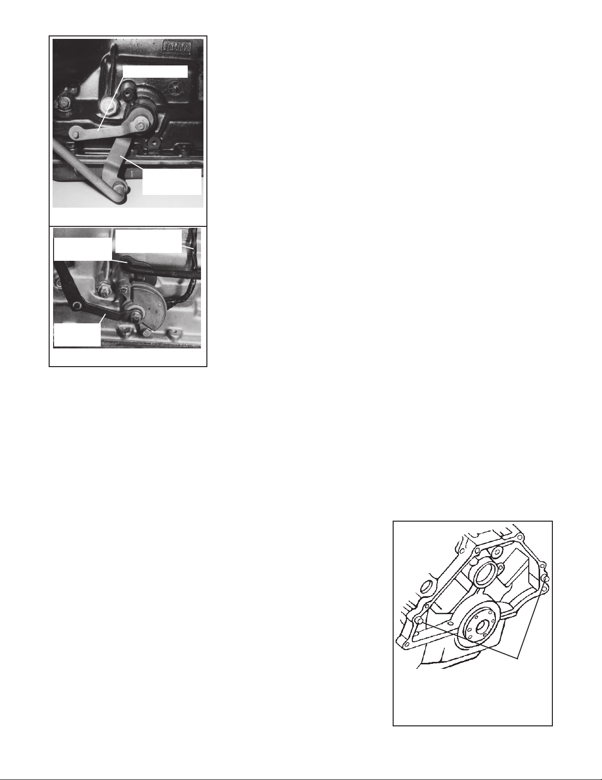
Kickdown lever
Column Shift
lever
Figure 1
Console Shift
lever
Kickdown
lever
You may lose some of the needle
bearings if the cups fall on the ground.
It is a good idea to tape the cups to the
U-joint cross, so they won’t fall off.
Now is a good time to clean and inspect your U-joints.
STEP 3. Disconnect vacuum line to
vacuum modulator. Disconnect
kickdown linkage. (See Figs. 1&2)
Remove clip holding rod or cable to
kickdown lever and allow rod or cable to
hang free. Disconnect shifter:
Column Shift Models: Disconnect
rod or cable from shift lever on transmission. (See Fig. 1) The rod or
cable is retained by a clip or by
snapping into a plastic grommet.
Remove clip or pry rod out of grommet and allow linkage to hang free.
Cable models; unbolt cable bracket
from bell housing and allow cable to
hang free.
Console Shift Models: Disconnect
rod from shift lever on transmission.
(See Fig. 2) The rod is retained by a
clip or by snapping into a plastic
grommet. Remove clip or pry rod out
of grommet and allow linkage to hang
free.
'70 and Later Vehicles Equipped
Neutral saftey
switch harness
Figure 2
With Locking Steering Column And
Console Shifter: Disconnect col-
umn lock rod from transmission shift
lever and allow it to hang free.
4 Wheel Drive Models: Remove
knob from transfer case shift lever.
STEP 4. Loosen and disconnect speedometer cable:
Clamp Type Cable: Remove bolt or
speedometer cable clamp. Pull
speedometer cable out of extension
housing and let it hang free.
Sleeve Type Cable: Loosen cable
sleeve. Pull speedometer cable out of
speedometer housing and let it hang
free.
STEP 5. Disconnect oil cooler lines.
Use a fitting wrench, if available, to avoid
damage to compression nuts. We
recommend that the oil cooler lines be
flushed out to remove any foreign particles trapped in the cooler. Cooler lines
should be flushed in both directions with
solvent and air pressure.
STEP 6. Remove dipstick and tube
assembly. Remove torque converter
access cover bolts and remove converter access cover. Remove flexplate
to converter nuts. Use starter motor to
“bump” each bolt into position.
STEP 7. Disconnect neutral safety
switch on vehicles equipped with neutral safety switch mounted on the transmission by unplugging connector ends
on wire harness. Allow connector ends
to hang free.
STEP 8. Remove starter motor assembly and tie it up out of the way. On some
vehicles, it is difficult to remove the
starter completely, so it is easier to
simply support it out of the way.
STEP 9. Support the transmission with
a jack. Remove the transmission rear
mount bolts. Raise the transmission
slightly and remove the crossmember.
Be sure the transmission jack supports
the transmission on a wide area so you
don’t crush the oil pan.
STEP 10. Remove the bellhousing
bolts. Lower transmission until the
engine is supported. Pull transmission
back slightly away from engine. Make
sure converter stays with transmission.
Lower transmission/converter assembly and remove from vehicle. Caution:
4 Wheel Drive Vehicles: Transmission/converter transfer case assembly
is heavy. Exercise care during removal
if your transfer case bolts to the transmission.
STEP 11. Pull converter off the front of
the transmission. Some oil will leak
out at this time. On C-4, C-6 and AOD
transmission, the input shaft may pull
out of the transmission when you remove the torque converter. Do not be
alarmed.
C-4: Install the short splined end
of the input shaft into the transmission until the splines engage the
drum inside the transmission. Push
the shaft in all the way until it stops.
C-6: Install the long splined end of
the input shaft into the transmission
until the splines engage the drum
inside the transmission. Push the
shaft in all the way until it stops.
Important C-4 ONLY: C-4 transmissions have either a 24T or 26T (Early &
Late models) spline input shaft. Remove the input shaft and insert it into
your B&M converter. Be sure that the
input shaft engages the spline inside of
the torque converter and is a good fit
into the spline. Install input shaft into
transmission as previously described.
STEP 12. Inspect your engine block
and engine plate. Make sure there are
no burrs that will prevent the transmission from bolting down flat against the
engine. File off any burrs that may be
present. Dowel pins should stick out of
the engine block a minimum of 1/2" for
proper alignment. (See Fig. 3) Insufficient dowel pin engagement can cause
front seal and/or bushing failure due to
improper engine/transmission alignment. Bellhousing bolts alone will
not align the transmission properly.
Dowel pins must
stick out 1/2" for
proper transmission engagement
Figure 3
Page 3

Inspect converter stud holes, crankshaft
bolt holes and starter ring gear teeth for
damage, cracks and excessive wear.
Figure 4
STEP 13. Inspect your flexplate. Check
for distortion, excessive warpage or
worn/elongated stud holes. (See Fig.
4) The flexplate should not be “dished”
backwards. Check condition of starter
ring gear teeth. Distorted or worn
flexplates should be replaced.
STEP 14. Check the bolt pattern of
your B&M torque converter and make
sure it matches your flexplate. There
are several bolt patterns possible from
Ford Motor Company:
C-4: (4) 3/8" studs on 11.40" B.C.
(4) 3/8" studs on 10.50" B.C.
(4) 3/8" studs on 9.28" B.C.
C-6: (4) 3/8" studs on 11.40" B.C.
(4) 3/8" studs on 9.28" B.C.
B&M Converter Applications
Converter B&M B&M Converter Flexplate
Part Number Converter Bolt Pattern Modifications
40425 C-6 Traveler 3/8"-24 x 11.40" B.C. Stock flexplate
40412 C-6 Holeshot 2400 7/16"-20 x 11.40" B.C. Drill 15/32"
40422 C-6 Holeshot 2400 7/16"-20 x 11.40" B.C. Drill 15/32"
40442 C-6 Holeshot 3000 7/16"-20 x 11.40" B.C. Drill 15/32"
40427 C-6 TorkMaster 2000 7/16"-20 x 11.40" B.C. Stock flexplate
50412 C-4 Holeshot 2400 3/8"-24 x 10.50" B.C. Stock flexplate
50416 C-4 Holeshot 2400 3/8"-24 x 10.50" B.C. Stock flexplate
50432 C-4 Holeshot 3000 7/16"-20 x 10.50" B.C. Drill 15/32"
50436 C-4 Holeshot 3000 7/16"-20 x 10.50" B.C. Drill 15/32"
50440 C-4 TorkMaster 2000 3/8"-24 x 10.50" B.C. Stock flexplate
40430 AOD Holeshot 2400 7/16"-20 x 11.40" B.C. Drill 15/32"
40431 AOD Holeshot 3000 7/16"-20 x 11.40" B.C. Drill 15/32"
40437 AOD TorkMaster 2000 3/8"-24 x 11.40" B.C. Stock flexplate
Note: B&M AOD 40430 & 40431 Open Converters (non-split path) do not
require any transmission modifications.
Refer to the following chart for flexplate and starter nose-piece cross reference.
Stock Flexplate Replacement Starter Nosepiece
Flexplate
C-4 Applications
C5AZ-6375-T Do not change Use same starter
11.40" bolt circle nosepiece
164 tooth ring gear
D5ZZ-6375-A C3AZ-6375-L D1AZ-11130-A
9.28" bolt circle 10.50" bolt circle
141 tooth ring gear 157 tooth ring gear
FMX: (4) 3/8" studs on 11.40" B.C.
(4) 3/8" studs on 10.50" B.C.
(4) 3/8" studs on 9.28" B.C.
AOD: (4) 3/8" studs on 11.40" B.C.
If your flexplate does not match up
to the bolt pattern on your B&M torque
converter, you will have to replace your
flexplate. You may enlarge your original flexplate holes to accept larger 7/
16"-20 studs used on most B&M Performance coverters. Use a 15/32" (.468")
dia. drill and deburr the holes after
drilling.
C-6 Applications
D1ZZ-6375-C D1ZZ-6375-A Use same starter
9.28" bolt circle 11.40" bolt circle nosepiece
164 tooth ring gear 164 tooth ring gear
AOD Applications
Use same flexplate
Factory part numbers are for reference only, and are not guaranteed for
accuracy.
Make sure that the replacement flexplate has an equivalent balance weight
on it. Improper flexplate balance will cause severe engine vibration.
Page 4

Note: C-4 transmission bellhousings
have two different mounting designs.
1. Flared case: The bellhousing bolts
directly to the transmission case with
5 bolts and the oil pump bolts are
separate. (See Fig. 5) The case flares
out to meet the bellhousing.
2. Pump Mount: The bellhousing bolts
to the transmission with the same
bolts that hold the oil pump. (See Fig.
6) There is a 1/4" gap between the case
and the bellhousing.
Caution: Do not use a 10.50" bolt
circle torque converter with a flared
case bellhousing C-4. Do not use an
11.40" bolt circle converter with Pump
Mount bellhousing C-4. Improper pilot
hub or oil pump engagement will result
which could damage the transmission
and/or torque converter.
STEP 14. Install flexplate onto crankshaft if you have removed or replaced
it. When properly installed, the raised
inner lip on the flexplate crankshaft
diameter is away from the crank-
shaft. Install flexplate to crankshaft
bolts and torque to 55 lb. ft.
STEP 15. Install B&M torque converter
against crankshaft and flexplate. The
converter should fit the crank snugly
with no excessive slop. A tight fit may
indicate burrs or rust in the pilot diameter of the crank. This can be cleaned
with some emery paper or a file. If your
flexplate is new or in good condition the
converter may not contact the flexplate
before it bottoms in the crankshaft. A
1/16 - 1/8" gap is normal. When the
flexplate to converter bolts are tightened the flexplate will bow backwards
slightly and hold the torque converter
against the crankshaft. Make sure
flexplate clears any drain plugs on
converter.
STEP 16. Remove the front pump seal
in the transmission and replace with
the new seal supplied with the converter. Lubricate the seal with ATF or
white grease. Pour one quart of B&M
Trick Shift ATF into the B&M torque
converter so there will be some lubrication on initial start-up. While Trick Shift
is superior in lubrication, heat capacity
and friction material performance, if
Trick Shift is unavailable be sure to use
Ford Type F fluid.
STEP 17. Install B&M torque converter
onto transmission. Push and rotate
C-4 Flared case 289, 302,
351C,351W
C-4 Step case 289, 302,
351C,351W
converter to engage input shaft, stator
shaft and oil pump rotors. Place a
straightedge across the face of the
transmission bellhousing. Measure the
distance from the face of the bellhousing
to the base of the torque converter drive
stud. (See Fig. 7) The base of the stud
must be at least 13/16" (4 cyl-351 V-8)
or 1-1/8" (360 Larger-V-8) inside the
bellhousing. A measurement of less
than 13/16" (4 cyl-351 V-8) or 1-1/8"
(360-Larger V-8) indicates the torque
converter is not fully engaged in the
transmission, except torque converters specially built for motor plate applications. (Subtract the thickness of
your motor plate from the 13/16" or 1-1/
8" dimension for proper measurement.)
Continue to rotate and turn the converter to obtain full engagement. If you
install the transmission without full
converter engagement, you will
damage the oil pump and/or converter.
STEP 18. Place transmission in posi-
tion on transmission jack. Be sure the
jack supports the transmission on a
wide area so you don’t crush the pan.
Align converter drive studs with holes in
flexplate. Install transmission/torque
converter against engine. Transmission should engage dowel pins and sit
flat against the engine block with hand
pressure only. If the transmission will
not sit flat against the engine, the converter is not installed into the transmission all the way or there is some inter-
Figure 5
Figure 6
C-4 Flared case
C-4 Step case
ference problem. Do not attempt to
pull the transmission up against the
engine with the bellhousing bolts
as this can cause transmission and/
or torque converter damage.
STEP 19. Once the transmission is in
position against the engine, install transmission bellhousing bolts and tighten
25-30 lb.ft. At this point, the torque
converter should be free to move back
and forth slightly. A tight converter
indicates improper pump engagement,
badly burred crankshaft, distorted
flexplate or flexplate stud holes not
drilled to size. This condition must
be corrected before going any further.
STEP 20. Inspect rubber transmission
mount. Worn, cracked or oil soaked
transmission and/or engine mounts
should be replaced. Raise transmission and install crossmember and transmission mount bolts securely. Install
starter motor in place. Install starter
bolts and tighten securely. Connect
neutral safety switch on vehicles with
switch mounted on transmission.
STEP 21. Install four flexplate to converter nuts. Use the starter motor to
“bump” each stud into position. Tighten
nuts:
3/8" - 24 23 - 28 lb.ft.
7/16" - 20 26 - 32 lb.ft.
Install converter access cover and
tighten bolts 30-60 lb.in.
Page 5

Drive lug face (base of stud) must be at
least 13/16" (4 cyl to 351 V8) or 1-1/8" (360
to Larger V8) inside front edge of
bellhousing
Figure 7
STEP 22. Install dipstick and tube
assembly. Use a small amount of
sealer on dipsticks with an O-ring to
prevent leaks. Connect oil cooler lines.
Use a fitting wrench on the compression nuts to avoid damage to the nuts
and hold the fittings with a wrench while
tightening compression nuts 75 lb.in.
STEP 23. Connect speedometer cable:
Clamp Type Cable: Use a small
amount of sealer on the O-ring to prevent leaks. Push speedometer cable
assembly into extension housing. Install clamp bolt and tighten to 150 lb.in.
Sleeve Type Cable: Push speedometer cable into speedometer housing
and tighten sleeve.
STEP 24. Connect shifter:
Column Shift Models: Connect rod or
cable to shift lever on transmission.
(See Fig. 1) Snap rod into grommet
retainers by squeezing rod and lever
together with a pair of pliers. Connect
rod or cable to clip retainer levers and
install clip.
Console Shift Models: Connect rod
to shift lever on transmission. (See Fig.
2) Snap rod into grommet retainers by
squeezing rod and lever together with a
pair of pliers. Connect rod to clip
retainer levers and install clip.
'70 and Later Vehicles Equipped
With Locking Steering Column And
Console Shifter: Connect column
lock rod to transmission shift lever and
install clip. Check shifter adjustment.
Selector lever must coincide with detent feel in transmission. There must
be equal clearance between the Neu-
tral stop and detent position and the
Drive stop and detent position.
4 Wheel Drive Models: Install knob
on transfer case shift lever.
STEP 25. Connect kickdown linkage.
(See Fig. 1 & 2) Connect rod or cable
kickdown lever and install clip. Kickdown
linkage should work smoothly with a
positive spring return action.
STEP 26. Inspect vacuum line. Replace any vacuum lines that are broken, cracked, kinked or restricted. Vacuum source should be from the manifold for proper vacuum sensing to automatic valve bodies.
STEP 27. Install driveshaft. Make sure
U-joint cups are installed properly.
Tighten U-joint bolts or nuts securely.
STEP 28. Lower vehicle but keep the
rear wheels off the ground if possible.
Add 3 quarts (C-4), 4 quarts (FMX) or 6
quarts (C-6 or AOD) of B&M Trick Shift
to the transmission. While Trick Shift
is superior in heat capacity, lubrication
and friction material performance, if
Trick Shift is unavailable be sure to use
Ford Type F fluid.
STEP 29. Start engine and place
shifter in the Neutral position. Add
fluid until the oil level is between the
Add and Full marks. Shift transmission through all gear positions. If the
rear wheels are off the ground, allow the
transmission to shift through all gears
several times. Place selector in Neu-
tral and check fluid level. Do not
overfill. This can cause foaming and
overheating. Check for leaks at cooler
lines, etc.
OPERATING RECOMMENDATIONS
Torque Converter Performance
The torque converter is a component of the automatic transmission
however it must be properly matched to
the engine for maximum performance.
A torque converter reacts to torque.
The more torque you put to the converter the better your performance.
However this torque must match the
operating RPM of the converter. To
make a converter operate properly, your
engine must make sufficient bottom-
end torque. You cannot build an
engine for an automatic transmission
the same way you would build an engine for a 4-speed because the operating ranges are different . Your engine
must be built to produce as much
bottom-end and mid-range torque
possible for your operating conditions.
This is especially important for good
street performance.
Do not make the mistake of overcamming your engine. You will need to
limit camshaft duration to 245o @ .050
for street engines. We also suggest
you run the cam 2o-4o advanced. Small
CFM carburetors give better bottomend response. Be careful not to over
carburete your engine.
Approximate stall speed of B&M
torque converters is indicated by the
B&M model. For example, a Holeshot
3000 has a stall speed of approximately 3000 RPM. This is a general
guide and should be used for reference
only. Exact stall speeds are impossible to predict. A specific stall speed
cannot be guaranteed due to the many
variables involved in each car. If you are
experiencing stall speed difficulties, the
following items can contribute to low
stall speeds:
Light cars
Small displacement engines
Very high compression ratios
Large throttle bore carburetors
Mechanical carburetor secondary
linkage
Long duration camshafts
Retarded cam timing
Poor rear brakes
High-ram manifolds
Multiple carburetion
Low stall speeds, poor throttle
response, sluggish performance and
Page 6

high idle speed requirements indicate
poor bottom-end torque characteristics which will need to be corrected
to obtain maximum converter performance.
Modified torque converters are installed
to improve performance and durability
not available from a stock torque converter. Heavy Duty and racing applications impose higher loads and greater
heat dissipation than stock operating
conditions.
Oil Cooling: The factory heat exchanger is usually inadequate for Heavy
Duty and/or Racing applications. The
following B&M Oil Coolers are recommended for performance applications.
Heat is the major enemy of automatic
transmissions and a cooler will also
prolong the life of your transmission.
B&M will not warranty torque converters which show heat damage from misuse or inadequate cooling.
B&M
Part No. Rating/Application
70255 16,000 GVW Street perfomance
70268 19,000 GVW Campers, small
motor homes, high stall converters
70264 24,000 GVW Large motor homes,
towing, high stall converters
70266 28,000 GVW Road & off-road race
cars (high flow race cooler)
Driving Techniques:
Traveler:
Traveler torque converters should
be driven like a stock torque converter.
Stall speeds and converter slip will
coincide with torque demand and adjust automatically. Additional deceleration will be noticed during manual
downshifts.
Holeshot and TorkMaster:
Holeshot and TorkMaster torque converters are designed for street performance and should not be considered
as a low cost race converter. Under
normal driving conditions Holeshot and
TorkMaster torque converters will function like stock converters with some
additional slip. High stall speeds are
available at torque demand. The best
standing start acceleration performance
is usually obtained by “stalling” the
converter at 1500-2000 rpm with the
brakes locked just prior to launching
the car. Bang the throttle and release
the brake pedal at the instant of launch.
Marginal traction situations may require you to “drive the car out” or feel for
traction with the gas pedal as you leave
the starting line. Remember, Holeshot
and TorkMaster torque converters are
designed for street performance and
occasional drag strip use. Race cars
need Race converters.
Maintenance:
Street Use: Change fluid and filter
every 10,000 - 12,000 miles. This will
also help the life of the transmission.
Check torque converter bolts or nuts
every 20,000 - 24,000 miles.
Ballooning: Ballooning is expansion
of the torque converter along the axis of
rotation (front to back). This is caused
by high rpm use and/or continuous
wide open throttle stall speeds. A
ballooned converter can lose thrust
washer piloting and must be cut open
for repair. You can check for ballooning
by measuring the end play clearance of
the stator and turbine. (See Fig. 8) You
will have to make a hooked tool to grab
the stator or turbine. (See Fig. 9) Maximum stator or turbine end play is .050
inch. If stator or turbine end play
exceeds .050 inch the converter will
have to be cut open to repair the cover.
Cracks and Leaks:
Leaks can be caused by several
reasons. The most common are front
seal failure and vibration cracks.
Front seal failure is due to improperly installed seal (damaged during installation), misalignment, worn pump
bushing, or worn converter impeller hub.
A ballooned converter can have a slightly
bent impeller hub. Inspect the pump
bushing when you replace the seal.
Check dowel pins in the engine block
for sufficient engagement and polish
the converter impeller hub with 400 grit
wet and dry sandpaper and oil.
Cracks can develop in the impeller
hub or perimeter weld from stress and
vibration. If a crack occurs around the
impeller or pilot hub we recommend
you return it for repair.
Measure end play
by hooking the
tool to the stator and
lifting up and down
12"
Typical homemade tool
used to check torque
converter end play
Figure 8 Figure 9
 Loading...