

Page 1

Installation Instructions
QuickSilver Shifter
Part Number 80683
©2010, 2003, 2000 by B&M Racing and Performance Products
The B&M QuickSilver Shifter can be
used in most vehicles equipped with three
speed or four speed automatic transmissions. Your B&M QuickSilver Shifter
comes equipped with a neutral safety
switch and a backup light switch, transmission brackets, levers and a five foot
shift cable. Optional shifter cables in 2 ft.
(#80830), 3 ft. (#80831), 4 ft. (#80831), 8
ft. (#80831), 10 ft. (#80835) and 12 ft.
(#80836) are also available. To use the
B&M QuickSilver Shifter with the Ford
AOD transmissions you will need the optional accessory kit #40496. To use the
B&M QuickSilver Shifter with the GM
4L60E, 4L65E, 4L80E, and 4L85E
equipped with a PRNDL switch you will
need optional accessory kit #75498 otherwise you can use the supplied GM
bracket.
To use this shifter with a GM four
speed automatic transmission, you will
need to remove the three speed limiter
blocker pin and the two e-clips (See Fig-
ure 1). For the Ford AOD four speed
transmissions do not remove this blocker
pin.
To use this shifter with a Ford or
Chrysler automatic transmission, install
the blocker pin and the two e-clips (See
Figure 1). This limiter limits the travel of
the shifter when it is shifted into Park, so
that it does not stretch the cable.
Please read the instructions and review the illustrations thoroughly before
beginning the installation.
The mechanical components of this
shifter are precision made and assembled
at our factory. Any modification or disassembly of these parts can cause the shifter
to malfunction and will void the warranty.
You should disassemble only those items
outlined in the instructions.
Printed in the U.S.A.
The vehicle should be about 2 feet off
the ground for ease of installation. Use
jack stands, wheel ramps or a vehicle lift.
Make sure the vehicle is firmly supported
before attempting to work on it.
IMPORTANT: If your vehicle is equipped
with a locking steering column. Securing
the column lock lever in the engine compartment in the full up position will allow
the steering wheel to be locked and unlocked and the ignition key to be removed.
WARNING: This allows the steering wheel
to be locked WHENEVER the ignition key
is turned to the “lock” position WHILE
THE VEHICLE IS MOVING, OR AT ANY
OTHER TIME. Securing the steering column lock lever in any other position will
both PREVENT the steering wheel from
locking and the removal of the ignition
key.
INSTALLATION
NOTE: If you are installing this shifter with
a GM four speed automatic transmission,
you must remove the three speed limiter
blocker pin and the e-clips indicated in
Figure 1. Removing this blocker pin gives
the shifter four forward positions rather
than three. For Ford AOD four speed
automatic transmissions and Chrysler A500 and A-518 four speed automatic transmissions do not remove this blocker pin,
since these transmissions have only three
forward positions. Also do not remove
the blocker pin and the e-clips for any
three speed automatic transmissions.
(The three speed limiter blocker pin goes
in the upper of the two holes at the rear of
the shifter).
If you are installing this shifter with a
Ford or Chrysler three or four speed automatic transmission you must install
the Park limiter blocker pin and the eclips as also indicated in Figure 1. This
limiter limits the shifter travel into the Park
position, since Ford and Chrysler transmissions have less travel between Reverse and Park than GM transmissions
do.
STEP 1. Remove the stock shift linkage;
Column Shifters: Remove all rods, le-
vers or cables from the column and the
transmission. Place the column shift lever in Park position. Remove the pin
holding the shift lever in the column and
remove the lever assembly. If your vehicle is equipped with a locking steering
column, secure the column lock lever in
the full up position. WARNING: This allows the steering wheel to be locked and
the ignition key removed WHENEVER
the ignition key is turned to the “lock”
position WHILE THE VEHICLE IS MOVING, OR AT ANY OTHER TIME.
Console Shifters: Remove the shifter
mechanism from the console. Disconnect the rod or cable from the transmission. Remove the cable bracket if
equipped. If there is a cable or linkage
from the console shifter or transmission
to the steering column lock, it must be
blocked in the Park position as described
above.
NOTE: Shifter installation may require
console modification or complete console removal depending on the space
available in your vehicle.
STEP 2. Pull the carpet away from the
floorboard where the shifter is to be
mounted. If the vehicle has a bench type
seat, move the seat to the full forward
position. Place the shifter on the floor with
the stick shifted to the rearmost position.
Locate the shifter for ease and convenience of operation. (The rear mounting
9500662-06
Page 2
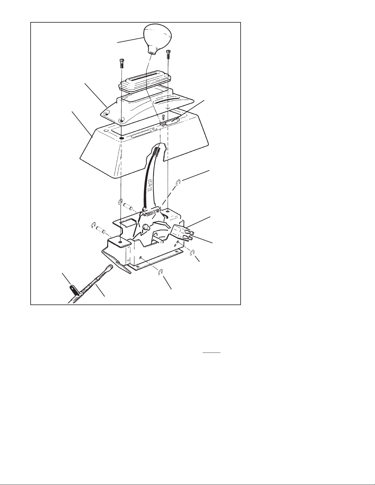
Knob
Top cover
Tower
Tab must be bolted to
the OUTSIDE surface
of the shifter base
Cable
Figure 1
hole of the mechanism must be at least
1¾” from the front of the seat when the
seat is in the full forward position). Make
sure the knob clears the dash with the
shifter in the Park position. Mark the position of four mounting holes on the floor.
STEP 3. Drill the four 9/32" mounting
holes where marked. Temporarily mount
the shifter in place using the washers as
required to get it level. Mark the location
for the shifter cable hole, 3" ahead of the
front shifter mounting hole. Drill or cut a
1½” diameter cable hole in the floorboard.
NOTE: Some floorboards are extremely
thin and will not adequately support the
shifter mechanism when bolted to the
floor. For those vehicles we recommend
that you fabricate a stiffener plate for
additional strength.
STEP 4. Install (but do not secure) the
carpet back to it’s original position. Cut
Indicator
light
E-clip
Backup light
switch
Neutral safety
switch
Three speed limiter
blocker pin and e-clips
(in upper hole)
Park limiter blocker pin and e-clips
for Chryslers and Fords only
holes in the carpet for the mounting holes
and a 1½” slit for the cable. DO NOT use a
drill bit to make holes in the carpet.
STEP 5. Install the cable on the shifter as
shown in Figure 1. The cable attachment
tab must be bolted to the outside surface
of the shifter base using the supplied ¼” X
½” hex bolt, lock washer and nut. Put the
end of the indicator link on the cable pin
outside of the shifter cable. Install the eclip to secure the cable.
STEP 6. Install the backup light switch and
the neutral safety switch in place on the
shifter mechanism. Install them using the
two supplied #4-40 screws, nuts and lock
washers, as shown in Figure 1. If necessary, bend the fingers slightly so that they
engage the slots. Beware, overtightening
the switch attachment screws will crack
the switch housings. Adjust the switches
so that the neutral safety switch (the lower
2
switch) operates in Neutral and Park
only and so that the backup light switch
(the upper switch) operates in Reverse
only by loosening the screws and sliding the switch as required. Then retighten the screws.
STEP 7. Install the shifter mechanism
into the vehicle. Slide the shifter cable
through the carpet and the hole in the
floorboard. Bolt the shifter down using
four ¼” hex bolts and nuts. If required
use ¼” washers as shims between the
shifter mechanism and the floor to level
the shifter. ROUTE THE CABLE AS
SHOWN IN FIGURE 2, AVOID SHARP
BENDS WHICH WILL KINK AND DAMAGE THE CABLE. Use cable clamps or
tie wraps to secure the cable housing to
the chassis to avoid contact with hot
engine or exhaust system. Seal the cable
hole shut to avoid the entry of exhaust
fumes or water. For General Motors
vehicles go to Step 8, for Ford vehicles
go to Step 13, for Chrysler vehicles go
to Step 19.
GENERAL MOTORS
STEP 8. If you have not already done so,
remove the stock selector lever nut and
the selector lever. Discard the stock
lever and the stock shifter linkage. Install the B&M selector lever in position
using the stock selector lever nut (See
Figure 3). Torque the nut to 23 lb. ft. The
lever should move smoothly from front
to rear with a positive click in each gear
position.
STEP 9. Remove the two transmission
oil pan bolts from the middle of the left
side of the oil pan. Install the cable
bracket in position (See Figure 3). The
bracket must be installed with two spacers between the pan and the bracket. (If
your transmission is equipped with a
cast aluminum oil pan, these spacers
should be omitted however the cable
bracket may have to be modified). Install the two supplied 5/16-18 x 1.00"
bolts and tighten to 12-13 lb. ft. Do not
overtighten as this can damage the pan
gasket.
Note: In some cases possible modification to the GM cable bracket might
be required for the 4L80E and 4L85E
transmissions without the PRNDL
switch. Verify that selector lever does
not grind on cable bracket before
moving on to step 10.
STEP 10.Route the shifter cable ac-
cording to Figure 3. Avoid kinks and
sharp bends and route the cable away
from hot engine or exhaust parts.
Remove the two rubber boots, one
large nut, and a large lockwasher from
Page 3
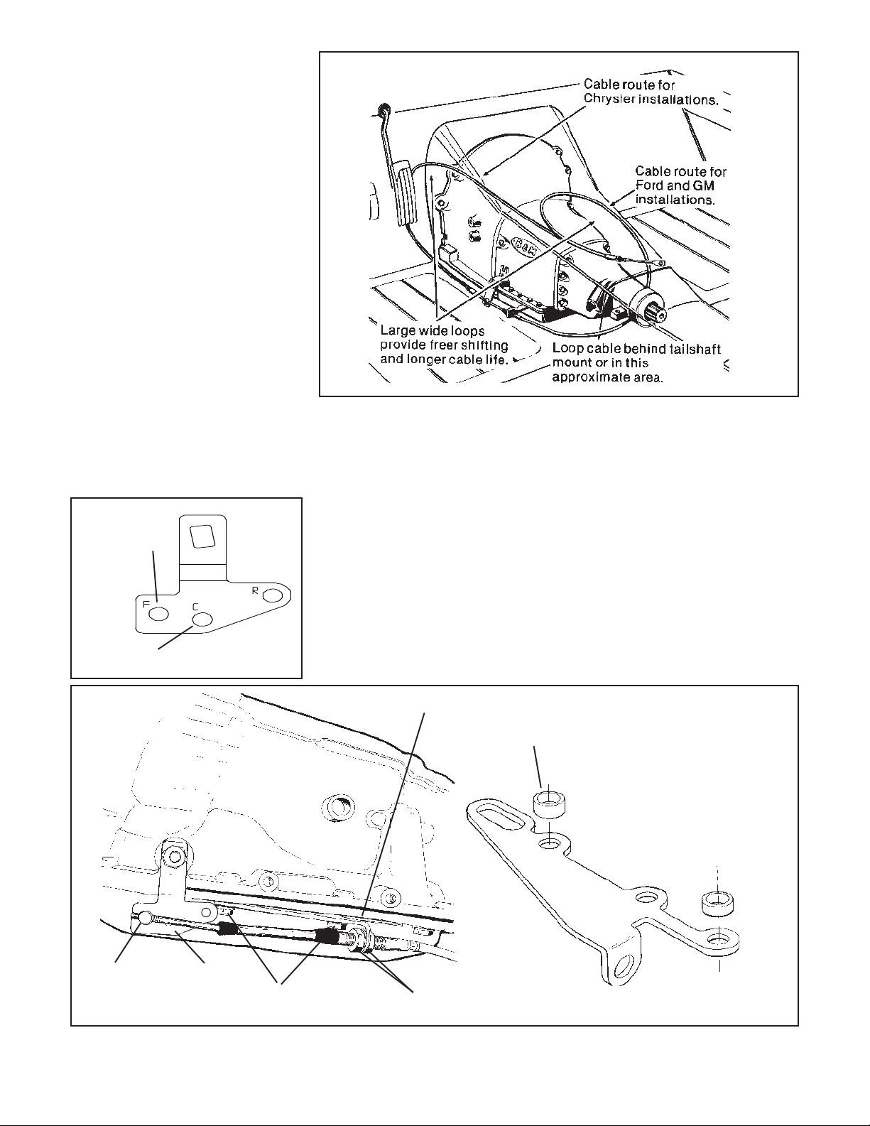
the threaded end of the shifter cable.
Slide the end of the cable into the cable
bracket. Install the large nut and the
lockwasher loosely over the end of the
cable. Install the two rubber boots onto
the end of the cable. Install the swivel on
the threaded end of the cable and position it in the center of the threaded portion.
STEP 11. If you have a four speed automatic transmission, be sure that you have
removed the three speed limiter blocker
pin shown in Figure 1. If you have a three
speed automatic transmission, the three
speed limiter blocker pin and e-clips
should be installed. The Park limiter
blocker pin and e-clips should not be
installed for any GM transmission.
Move the transmission selector lever
by hand to the full rear position (Low).
Shift the shifter mechanism to the Low
gear position (ratcheted all the way back).
Adjust the large nuts on the cable so that
the swivel will slide into the hole on the
selector lever. Tighten the large nuts completely. Be sure that the swivel will slide
freely in and out of the hole in the selector
lever. Note: The shifter will not operate
correctly unless the correct hole in the
shift lever is used as shown below:
Use with four
speed
transmissions
Use with three speed
Figure 2
Leave the swivel out of the hole and
move the selector lever to Park, all the
way forward. Also move the shifter to Park
position. (See operation section, page
7). Reinsert the swivel into the hole in the
selector lever. Check to see that the swivel
will slide freely in and out of the hole in the
selector lever in this position. If it does not
slip in freely, adjust the swivel slightly
until it will slip into the hole in the lever.
Move the shifter back to the Low gear
position and check that the swivel will still
slide easily in and out of the hole in the
selector lever. (If you do not use the hole
in the lever, it will be impossible to cor-
rectly adjust the cable). Operate the shifter
through all the gear positions. Check to
make sure the swivel will slide in and out
of the selector lever hole in each gear
position. The shift cable is now correctly
adjusted. Install the cotter key supplied
with the shifter into the swivel and spread
the key ends.
If you have a problem, DO NOT FORCE
THE SHIFTER, this will damage the cable,
the shifter or the transmission. Simply
start at the beginning and carefully check
all your steps.
STEP 12. On GM vehicles, the neutral
safety/backup light switch is located on
F
Cable swivel (4
speed shown)
Cotter pin
C
R
GM lever
5/16 x 1" bolt and spacer
(Metric trans use M8 x 25 bolt)
GM cable bracket
7/16" nut
Figure 3
3
Spacer
Use these two holes for
TH-400 transmission. Use
other two holes for other
GM transmissions
Spacer
GM cable bracket (Trimming of bracket
required if used on cast aluminum pan)
Page 4
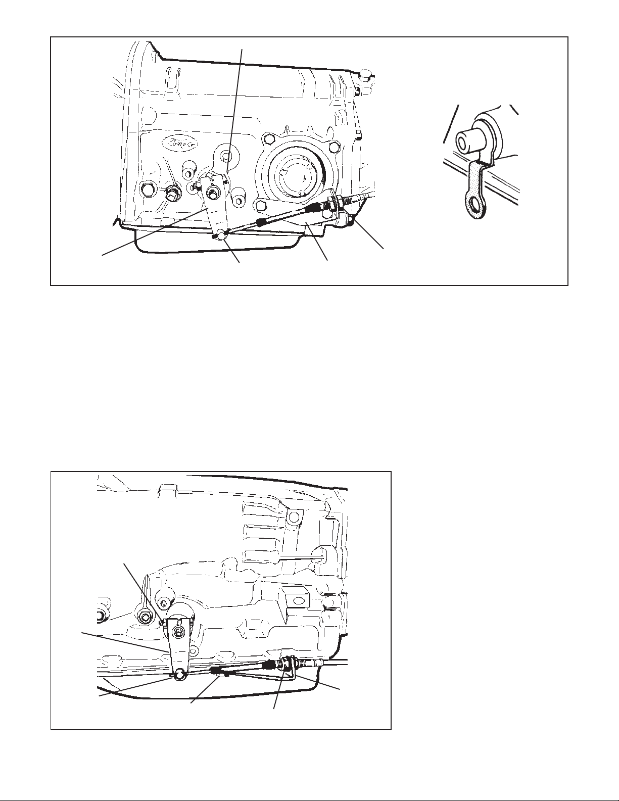
Ford lever
1/4 x 1-1/2" bolt, lockwasher and nut
7/16" nut
Cable swivel
Cotter pin
C-4 cable bracket
Figure 4
Remove shaded
portion of lever
the console shifter or the steering column. Locate and identify the neutral safety
switch (the engine will not crank unless
these wires are connected together). Disconnect the battery ground cable before
beginning to wire the neutral safety
switch. Reroute the wires to the B&M
QuickSilver Shifter.
On GM vehicles the neutral safety
switch may be located on the shifter (steering column or console), or it may be a
mechanical interlock in the steering column that prevents the key from turning to
the Start position unless the shifter is in
1/4" x 1-1/2" bolt,
lockwahsher, nut
Ford
lever
Cable swivel
Cotter pin
5/16" x 1" bolt
and spacer
the Park or Neutral position. Identify the
type of neutral safety system you have. If
the key will not turn to the Start position
unless the stock shifter is in Park or Neutral, you have a mechanical interlock,
otherwise you have a neutral safety switch.
With either type, disconnect the battery
ground cable to prevent accidental shorts.
If you have a neutral safety switch, locate
and identify the neutral safety wires (engine will not crank unless these wires are
connected together). Extend the wires
from the GM switch to the B&M
QuickSilver Shifter. Strip ¼" of insula-
C-6 cable
bracket
7/16" nut
tion off the wires and install the slip-on
terminals supplied in the kit. Crimp the
terminals onto the wires using a crimping
tool or pliers. Connect the neutral safety
wires to the LOWER switch and the
backup light wires to the UPPER switch
(See Figure 1). Tape the terminal connections and all other connections to prevent shorts.
If you have a mechanical interlock cut
the wire that goes from the start position
on the ignition switch to the solenoid on
the starter. This wire is usually a 10 or 12
gauge purple wire. Run the wires from
both ends of the cut wire to the B&M
QuickSilver Shifter. Put the slip-on terminals on the ends of the lengthened
wire. Crimp the terminals onto the wires
using a crimping tool or pliers. Connect
the wires to the LOWER switch on the
shifter. The backup light switch is usually
located on the steering column behind
the instrument panel. Lengthen these
wires and run them to the UPPER switch
on the shifter. Tape the terminal connections and all other connections to prevent
shorts.
Reconnect the battery ground cable,
disconnect the coil wire and set the parking brake. Check the switch operation by
attempting to start the motor in each shifter
position. The starter must crank only
when the shifter is in the Park or Neutral position. Check the backup light
operation when the shifter is shifted to
the Reverse position. Adjust the switches
if required. Reconnect the coil wire. Go to
Step 25.
Figure 5
FORD
4
Page 5
STEP 13. If you have not already done
so, remove the nut and the lockwasher
holding the downshift linkage onto the
downshift lever shaft. The downshift lever
is the outer lever on C-4, C-5 and C-6
transmissions. Pull the lever off the shaft
and allow the linkage to hang free. Remove and discard the stock shift linkage
rods. Some C-6, late C-4 and all C-5
transmissions have a neutral safety/
backup light switch on the transmission
shift lever. If your transmission is so
equipped, remove the two bolts holding
the switch in place and slide it off the shift
shaft. Disconnect the switch at the factory
plug and discard it.
STEP 14. Install the B&M selector lever
(See Figure 4 or 5). Note: The B&M lever
must point downward for proper operation. If the stock shift lever on your transmission points down, you will have to
remove the lower part of the stock arm by
cutting it off to clear the B&M lever (See
Figure 4). Install the B&M selector lever
onto the shift shaft of the transmission.
Align the selector lever so when it points
straight down it travels equal arcs in both
directions from the center, then tighten
the ¼”-20 x 1 ½” pinch bolt and the nut.
The lever should travel smoothly from
front to back with a positive click in each
gear position. Make sure the o-ring is in
position on the downshift shaft and install
the downshift lever in position on the
shaft. Install the lockwasher and the nut
and tighten securely. The downshift lever
must operate smoothly. Reconnect the
downshift linkage.
STEP 15. Cable bracket installation:
C-4, C-5: Remove the two lower bolts
from the rear servo cover. Install the cable
bracket in position (See Figure 4). Install
the two servo cover bolts as removed and
tighten to 12-13 lb. ft. Do not overtighten
as this can distort the servo cover.
C-6: Remove the two transmission oil
pan bolts from the left rear corner of the oil
pan. Install the cable bracket into position
with the two spacers between the pan and
the bracket (See Figure 5). (If your transmission is equipped with a cast aluminum
oil pan, these spacers can be omitted).
Install the two supplied 5/16-18 x 1.00"
bolts and tighten to 12-13 lb. ft. Do not
overtighten as this can damage the pan
gasket.
STEP 16. Route the shifter cable according to Figure 2. Avoid kinks and sharp
bends and route the cable away from hot
engine or exhaust parts.
Remove the two rubber boots, one
large nut, and a large lockwasher from
the threaded end of the shifter cable.
Slide the end of the cable into the cable
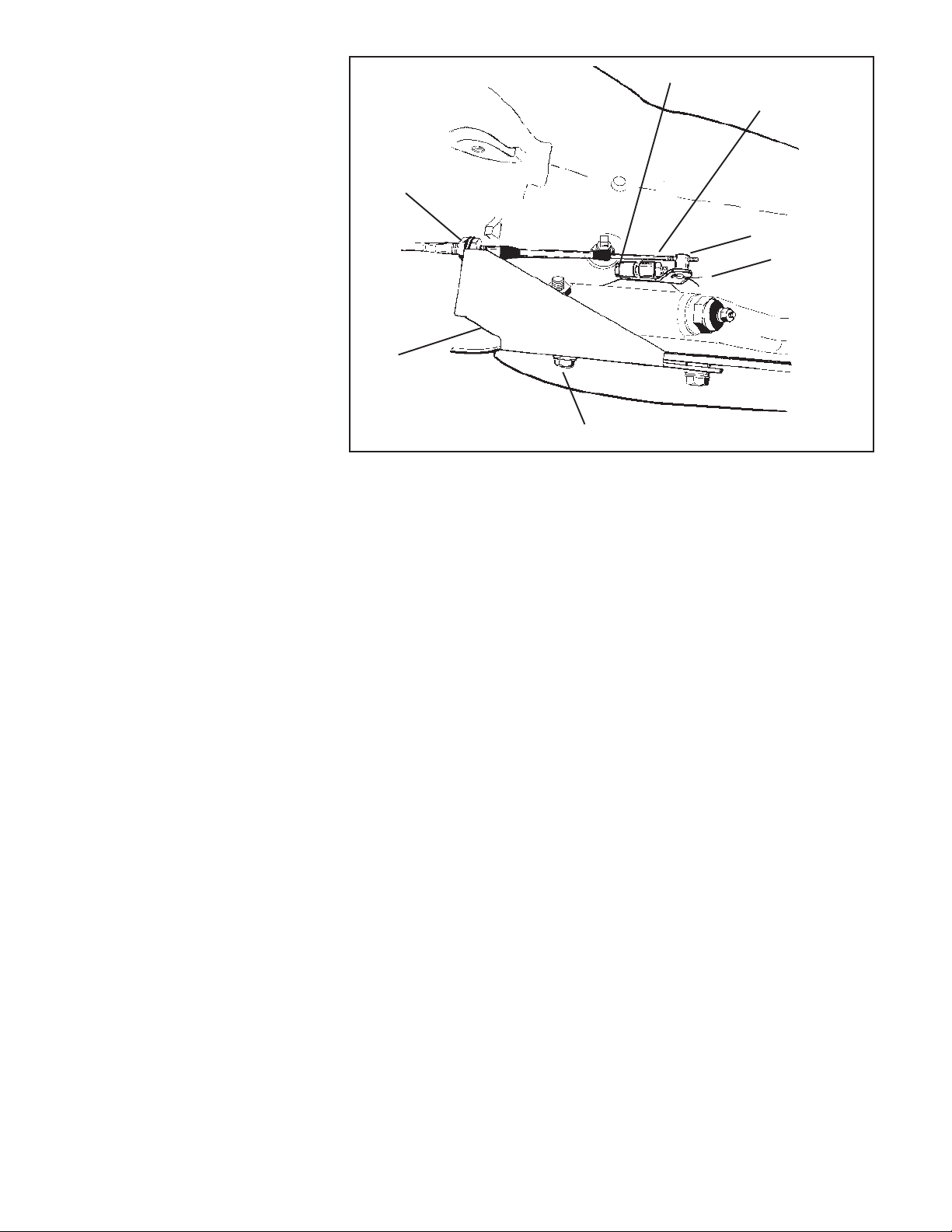
7/16" nut
Chrysler cable
bracket
5/16" x 1" bolt and spacer
Figure 6
bracket. Install the large nut and the
lockwasher loosely over end of cable.
Install the two rubber boots onto the end
of cable. Install the swivel on the threaded
end of the cable and position it in the
center of the threaded portion.
STEP 17. Be sure that the Park limiter
blocker pin and the three speed limiter
blocker pin are both installed as shown in
Figure 1. The Park limiter will prevent the
shifter from additional travel beyond the
Ford Park position. (GM transmissions
have greater travel between Neutral and
Park than Ford transmissions do). The
three speed limiter blocker pin is required
because all Ford three and four speed
automatic transmissions have only three
forward gear positions, even the four
speed AOD.
Move the transmission selector lever
by hand to full rear position (Low). Shift
the shifter mechanism to the Low gear
position (ratcheted back until it is stopped
by the three speed limiter blocker pin).
Adjust the large nuts on the cable so that
the swivel will slide into the hole on the
selector lever. Tighten the large nuts
completely. Be sure that the swivel will
slide freely in and out of the hole in the
selector lever.
With the swivel in the selector lever,
shift the shifter to the Park position, as far
forward as the shifter will go without forcing it. (The Park limiter blocker pin will
prevent the shifter from moving any further). The shift lever on the transmission
should be all the way forward. Check to
see that the swivel will slide freely in and
out of the hole in the lever in this position.
Chrysler lever
1/4" x 1-1/2" bolt,
lockwasher, nut
Cable swivel
Cotter pin
If it does not slip in freely, adjust the swivel
slightly until it will slip into the hole in the
lever in both Low and Park positions.
Operate the shifter through all the gear
positions. Check to make sure the swivel
will slide in and out of the selector lever
hole in each gear position. Install the
cotter key supplied with the shifter into the
swivel and spread the key ends. Reinstall the downshift linkage, tightening the
nut securely.
If you have a problem, DO NOT
FORCE THE SHIFTER, this will damage
the cable, the shifter or the transmission.
Simply start at the beginning and carefully
check all your steps.
STEP 18. On Ford vehicles, the neutral
safety/backup light switch is located on
the transmission (or on the steering column on some early vehicles). If the vehicle has an AOD transmission the neutral safety/backup light switches on the
B&M QuickSilver Shifter will NOT be
used. The neutral safety/backup light
switch on C-3 or AOD transmissions will
continue to function normally.
On the C-4 and C-5 transmissions it
is necessary to completely remove the
stock neutral safety/backup light switch in
order to install the B&M transmission shift
lever. On C-4, C-5 and C-6 transmissions,
it will be necessary to hook up the neutral
safety/backup light switches on the B&M
QuickSilver Shifter. Locate and identify
the neutral safety (the engine will not
crank unless these wires are connected
together), and reverse light wires. Disconnect the battery ground cable before
beginning to wire the neutral safety and
5
Page 6

Figure 7
reverse light switches. Reroute the wires
to the B&M QuickSilver Shifter. Strip ¼"
of insulation off the wires and install the
supplied slip-on terminals. Crimp the terminals onto the wires using a crimping
tool or pliers. Connect the neutral safety
wires to the LOWER switch and the reverse light wires to the UPPER switch
(See Figure 1). Tape the terminal connections to prevent shorts. Reconnect
the battery ground cable, disconnect the
coil wire and set the parking brake. Check
the switch operation by attempting to start
the motor in each shifter position. The
starter must crank only when the shifter
is in the Park or Neutral position. Check
the backup light operation when the shifter
is shifted to the Reverse position. Adjust
the switches if required. Reconnect the
coil wire. Go to Step 25.
CHRYSLER
STEP 19. If you have not already done
so, loosen the pinch bolt on the throttle
lever on the transmission. This is the
lever on the small diameter shaft. Pry the
lever off with a screwdriver and allow the
linkage to hang free. Remove and discard the stock shift lever and the stock
shift linkage. Install the B&M selector
lever in position and tighten the pinch bolt
securely (See Figure 6). Make sure the
lever is not pushed down so far as to
touch the transmission case. This will
cause the lever to bind on the case. The
lever should travel smoothly from front to
back with a positive click in each gear
position. Install the stock throttle lever
into position on the small diameter shaft
as removed and tighten the pinch bolt
securely. The throttle lever must operate
smoothly.
STEP 20. Remove the two transmission
oil pan bolts directly below the shift lever.
Install the cable bracket into position with
two spacers between the pan and the
bracket (See Figure 6). (If your transmis-
sion is equipped with a cast aluminum oil
pan these spacers can be omitted). Install the two supplied 5/16-18 x 1.00" pan
bolts and tighten to 12-13 lb. ft. Do not
overtighten as this can damage the pan
gasket.
STEP 21. Route the shifter cable according to Figure 2. Avoid kinks and sharp
bends and route the cable away from hot
engine or exhaust parts.
Remove the two rubber boots, one
large nut, and a large lockwasher from
the threaded end of the shifter cable.
Slide the end of the cable into the cable
bracket. Install the large nut and the
lockwasher loosely over end of cable.
Install the two rubber boots onto the end
of the cable. Install the swivel on the
threaded end of the cable and position it
in the center of the threaded portion.
STEP 22. Be sure that the Park limiter
blocker pin and the three speed limiter
blocker pin are both installed as shown in
Figure 1. The Park limiter will prevent the
shifter from additional travel beyond the
Chrysler Park position. (GM transmissions have greater travel between Neutral and Park than Chrysler transmissions
do). The three speed limiter blocker pin is
required because all Chrysler three and
four speed automatic transmission have
only three forward gear positions, even
the four speed A500 and A518.
Move the transmission selector lever
by hand to the full rear position (Low).
Shift the shifter mechanism to the Low
gear position (ratcheted back until it is
stopped by the three speed limiter blocker
pin). Adjust the large nuts on the cable so
that the swivel will slide into the hole on
the selector lever. Tighten the large nuts
completely. Be sure that the swivel will
slide freely in and out of the hole in the
selector lever.
With the swivel in the selector lever,
shift the shifter to the Park position, as far
forward as the shifter will go without forcing it. (The Park limiter blocker pin will
prevent the shifter from moving any further). The shift lever on the transmission
should be all the way forward. Check to
see that the swivel will slide freely in and
out of the hole in the lever in this position.
If it does not slip in freely, adjust the
swivel slightly until it will slip into the hole
in the lever in both Low and Park positions. Operate the shifter through all the
gear positions. Check to make sure the
swivel will slide in and out of the selector
lever hole in each gear position. Install
the supplied cotter key with the shifter
into the swivel and spread the key ends.
If you have a problem, DO NOT
FORCE THE SHIFTER, this will damage
the cable, the shifter or the transmission.
Simply start at the beginning and carefully check all your steps.
STEP 23. Check the operation of the
throttle linkage again. The linkage must
operate smoothly with no bind. All transmissions using automatic valve bodies
must have the throttle linkage connected
and operating or transmission damage
will result.
STEP 24. Neutral safety/backup light
switch.
’66-’68: The neutral safety switch will
continue to function normally. It will not be
necessary to hook up the neutral safety
switch wires on the shifter. Disconnect
the battery ground cable before wiring the
backup light switch. Locate the original
backup light switch on the steering column or the console shifter. Run these
wires to the UPPER switch on the B&M
QuickSilver Shifter (See Figure 1). Reconnect the ground wire and check the
light for proper operation. Adjust the
switches on the shifter if required.
’69 and Later: The neutral safety/backup
switch is located on the transmission and
will continue to function normally. It will
not be necessary to connect any wires to
the switches on the shifter.
STEP 25. Place the black tower over the
shifter mechanism until the bottom edge
of the tower touches the floor. Hold the
tower level to the shifter with the bottom of
the tower touching the highest surface on
the floor it will come into contact with (See
Figure 7). Use a ruler to measure the
distance X from the underside of the
tower to the tower mounting brackets on
the shifter mechanism.
STEP 26. Set a pair of dividers at the
distance X, measured in Step 25 . Holding the tower in position, place one leg of
the divider against the floor while the
other touches the tower (See Figure 7).
Using the dividers, scribe a line around
the tower that follows the contour of the
floorboard. Remove the tower and trim at
the scribe line using tin snips.
STEP 27. Mount the indicator light on the
tower (See Figure 1). The light socket
can mount on the top or the bottom of the
tower depending on the brightness desired. Mount the socket so the bulb is to
rear of the tower and secure it using one
10-24 self-tapping screw. Do not overtighten as you may strip out the hole in the
tower. Place the tower into position on the
shifter. Connect one wire from the light
socket to a good chassis ground. A shifter
mounting bolt should be satisfactory. Run
a length of wire from the vehicles instrument panel light circuit to the other wire
from the light socket. Secure and tape all
wires. Indicator light will work with the
instrument panel lights.
6
Page 7
STEP 28. Snap the indicator window in
place in the chrome top cover. The window snaps in from the top with the tabs
inserting under the cover. The indicator
window supplied with the shifter works
with standard shift pattern automatic transmissions. If your vehicle is equipped with
a reverse pattern manual valve body, you
need to use the indicator window #80618
for three speed transmissions and Ford
or Chrysler four speed transmission, or
#80898 for GM four speed transmissions.
These are available from your B&M
dealer.
STEP 29. Install the cover and the tower
into position on the shifter. Install four 1024 self-tapping screws in place on the
cover and tighten snugly. Two of the
screws continue through the tower into
the shifter tabs. Do not overtighten the
cover screws as this may distort or crack
the cover or the tower. Slip the boot over
the stick and position it on the cover.
Work the boot onto the cover until the slot
on the edge of the boot fits into the lip on
the cover.
STEP 30. Tighten the knob onto the stick
securely. Thread sealer will help keep the
knob from loosening. Position the knob
insert on top of the knob and align the
QuickSilver logo. Push down on the insert to snap it into place. Secure the
carpet to the floorboard and to the door
edges.
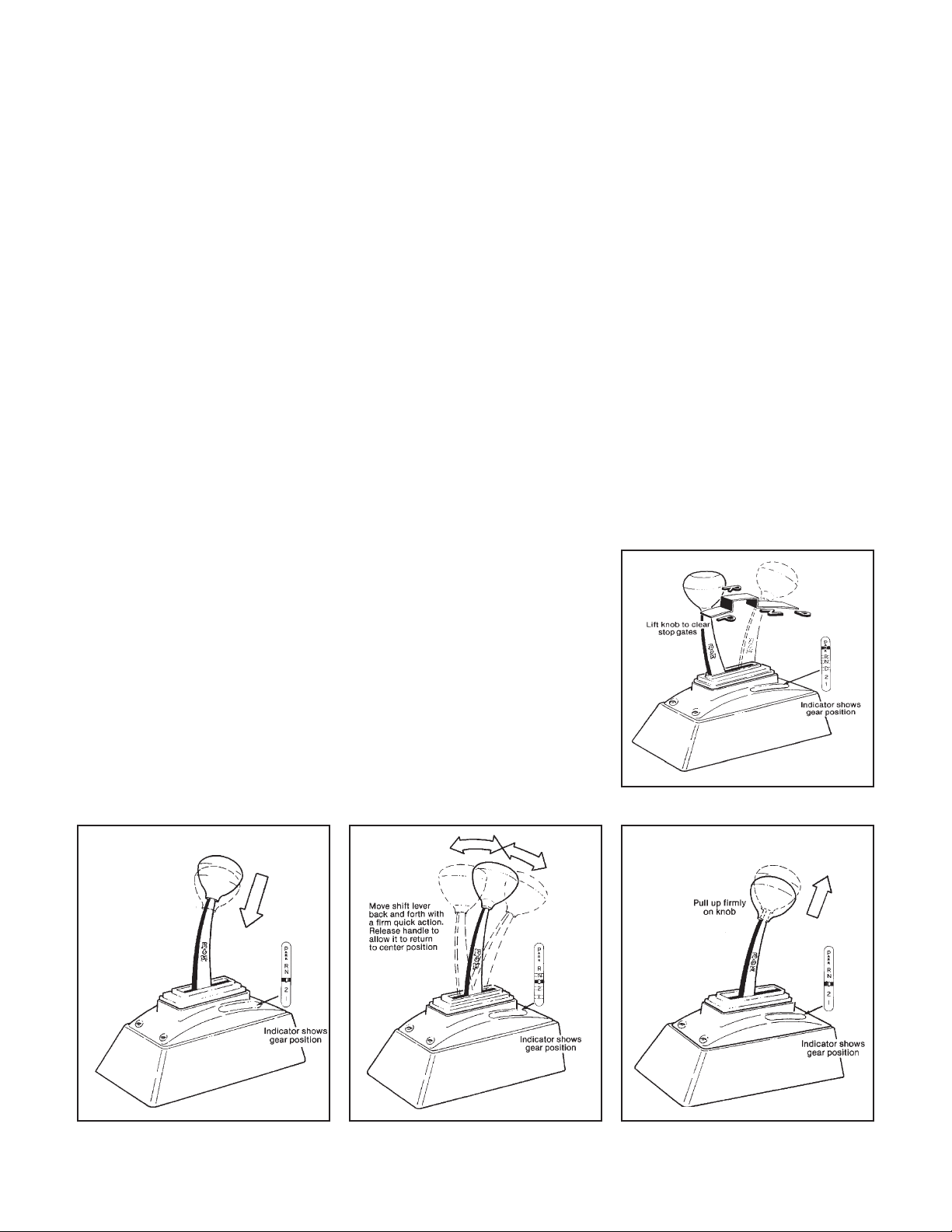
OPERATION
The B&M QuickSilver Shifter combines a straight gate shifter and a ratchet
shifter in one mechanism. Refer to the
following instructions for proper operation:
Straight gate mode: In the upper position, the shifter functions in the straight
gate mode. The stick travels in a direct
line forward and backwards from Park to
Drive. The shifter stick must be raised to
clear the stop gates when going through
the gear positions (See Figure 8).
Park: To get Park from any straight gate
gear position, lift the stick all the way
and push the stick all the way forward to
the Park position. Release the stick and
the shifter is locked in Park. To get to
any other gear position you must raise
the stick to clear the stop gates.
Reverse: Raise the stick to clear the
stop and move the stick to the Reverse
position.
Neutral:Move the stick to Neutral. You
do not have to raise the stick unless you
are in Park.
Drive: Move the stick to Drive. You do
not have to raise the stick unless you
are in Park.
Second and First gears cannot be selected when the shifter is in the straight
gate mode.
Ratchet Shift Mode: The ratchet shift
mode allows firm, positive, no-miss upshifts and downshifts in all forward gear
positions and Neutral. Reverse and Park
cannot be selected in the ratchet shift
mode.
To switch from straight gate to ratchet
operation, the shifter must be in the Drive
position. With the stick in the Drive position the stick will drop down to engage
rachet shift mode. The stick will snap
down approximately ¾”. The shifter is
now in the Drive gear position (See Fig-
ure 9).
Shifting in the ratchet mode: Move the
stick forwards or backwards with a quick
firm action until it hits the internal stop.
Caution: Do not lift the stick when making
ratchet shifts. Release the stick and allow it to spring return to the center position. The shifter is now ready for the next
shift (See Figure 10). Refer to the shift
indicator for gear positions in the ratchet
mode.
When the shifter has reached the
extreme rear gear indicator position, the
stick will contact the stop and you will not
be able to ratchet the stick towards the
rear.
The shifter is capable of ratcheting all
the way to Neutral. When the shifter
reached the Neutral position the shifter
will not ratchet any further.
To switch the shifter from ratchet mode
back to straight gate operation, ratchet
the shifter to the Drive position and pull up
firmly on the knob. You are now in the
straight gate mode, still in Drive (See
Figure 11).
Remember: To go from straight gate
mode into ratchet shift mode or from
ratchet mode into straight gate mode the
shifter must be put into the Drive position.
If these instructions for operating the
shifter seem complicated, do not be
alarmed. You will find that, in actual use,
the shifter will be extremely easy to operate after a minimal amount of experience
(See Figures 8, 9, 10 and 11).
3 speed shown
Figure 8
3 speed shown
Stick will drop
down to ratchet
shift mode when
placed in Drive
3 speed shown
3 speed shown
Figure 10Figure 9 Figure 11
7
Page 8
TOOL LIST
1 Phillips screwdriver
1 7/16 socket
1 Ratchet or speed handle
1 7/16" wrench
1 1/2" wrench
1 9/16" wrench
2 11/16 wrench
1 9/32 drill bit
1 drill motor
1 1-1/2" holesaw
1 Crimping tool
1 Torque wrench 0-50 lb. ft.
1 File
1 Tin snips
1 Wire strippers
1 Ruler
1 Dividers
1 Electrical tape
1 Hacksaw
1 Hammer
1 Drift pin
2-4 Jackstands
CHECK LIST
__ Locking steering column lever is permanently fastened in the full up
position. Step 1.
__ Shifter is convenient to reach and has ample room for your hand in both
park and low gear. Step 2.
__ Carpet covers floorboard holes. Step 4.
__ Cable is securely fastened to the shifter and held with e-clip. Step 5.
__ Shifter is securely mounted to floorboard. Step 7.
__ Shifter cable is clear of exhaust system, engine and any moving parts. Step
7.
__ Throttle lever and shift lever are tight on transmission. GM step 8, Ford
Step 14, Chrysler Step 19.
__ Oil pan bolts are tightened to 12-13 lb.ft. GM Step 9, Ford Step 15, Chrysler
Step 20.
__ Shifter is properly adjusted. Cable boots are installed, cable nuts are
tightened and swivel is secured with cotter key. GM Step 11, Ford Step 17,
Chrysler Step 22.
__ The neutral safety switch is connected and properly adjusted to prevent
engine starts in drive gears and reverse. GM Step 12, Ford Step 18, Chry
not required.
__ There is no debris in the shifter mechanism.
__ Tower is trimmed. Step 26.
__ Boot and tower effectively cover mechanism. Step 27.
__ Indicator clearly visible Step 29.
__ Shifter moves freely in all positions as described in Shifter Operation.
__ If your shifter is not working properly do not attempt to drive your car. Make
sure you have followed all instructions. If the shifter is broken or defective
return it to your B&M dealer.
WARNING
PERIODIC INSPECTION AND MAINTENANCE OF YOUR SHIFTER IS RECOMMENDED TO
ENSURE THAT THE MECHANISM IS WELL LUBRICATED, FREE FROM DIRT OR RUST AND
THAT THE CABLE IS PROPERLY ADJUSTED. LACK OF MAINTENANCE COULD RESULT IN A
FAILURE INCLUDING A FAILURE OF THE REVERSE LOCKOUT SAFETY FEATURE.
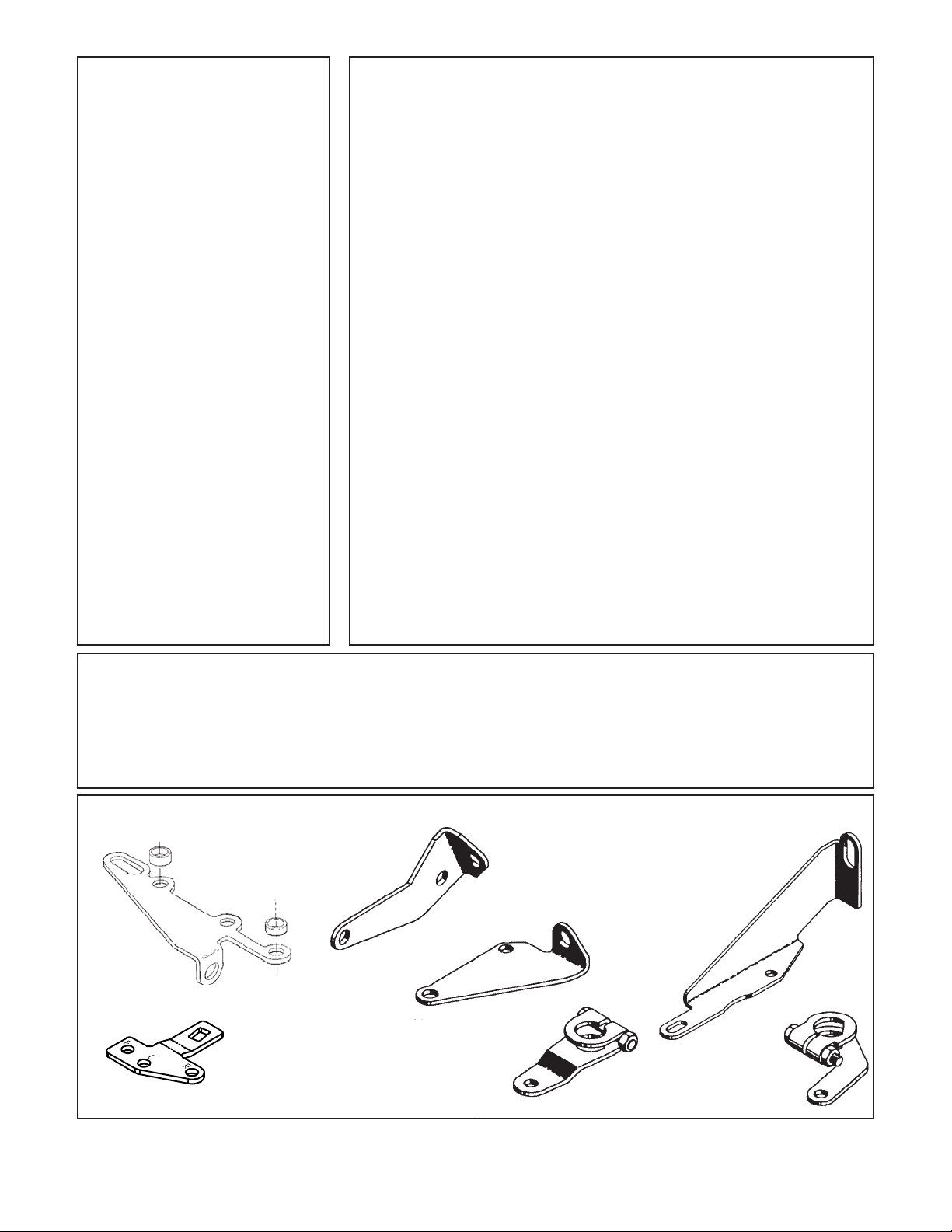
Note: Ford AOD Lever and bracket not shown
GM cable bracket
C-4 cable bracket
C-6 cable bracket
GM lever
Ford lever
Chrysler cable bracket
Chrysler lever
Cable brackets and levers
8
 Loading...