

Page 1
Installation Instructions
Power Switch
for GM Lockup Torque Converters
(All TH200C, TH250C, TH350C, TH200-4R
and 1982 thru 1989 TH700-R4)
Part Number 80217
© 2003, 2000 by B&M Racing & Performance Products
This kit will enable the driver to
control the operation of the torque
converter lockup clutch. The driver can
select between the converter's normal
function and having it unlocked in all
gears with a three speed automatic
transmission and in all gears but
overdrive (fourth) on four speed overdrive
transmission. Keeping the converter
out of lockup mode during city driving
saves wear and tear on the converter
clutch in addition to making the vehicle
more pleasurable to drive, as you will
no longer have the constant bump of
apply and release during stop and go
driving. The switch will not stop the
converter from locking up in fourth
(overdrive) gear of overdrive four speed
transmissions. GM four speed
transmissions should always be in
lockup mode in fourth gear due to the
increased possibility of overheating
the torque converter.
This kit will work on all TH200C,
TH250C and TH350C three speed
automatic transmissions. It will also
work with 1981-86 TH200-4R overdrive
automatic transmissions and on 1982
through 1989 TH700-R4 overdrive
automatic transmissions. (On 1990 and
later TH700-R4 transmissions the fourth
gear oil pressure tap has been
Printed in the U.S.A.
removed.)
Between 1979 and 1981 theTH200,
TH250 and TH350 three speed
automatic transmissions were made in
both lockup and non-lockup converter
versions. After 1981, only lockup
converter versions were manufactured.
A lockup torque converter transmission
can be identified by one or more wires
leading to a connector on the driver's
side of the transmission.
The power switch is simple to operate
and easy to install. You will need a
minimum of tools and mechanical
experience to install this kit. The tool
list and parts lists are on the last page.
Carefully read these instructions and
take your time with each step.
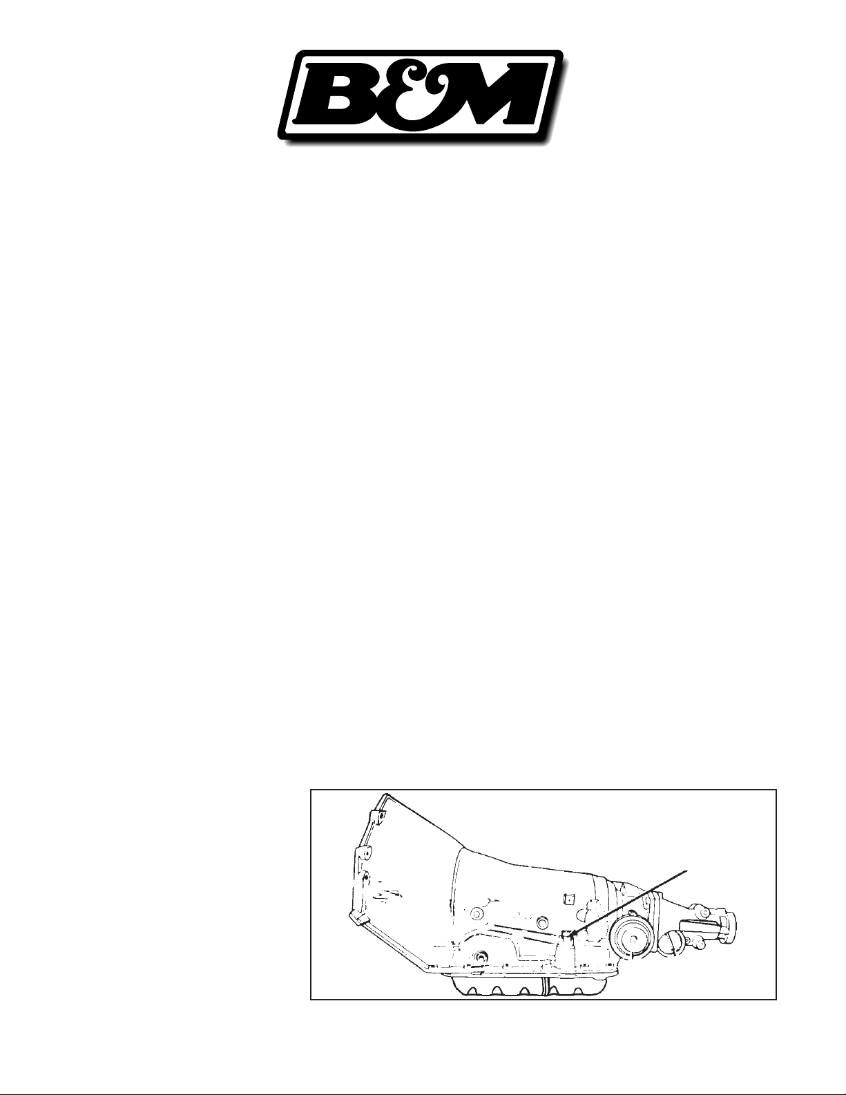
Figure 1
INSTALLATION TH200C,
TH250C AND TH350C THREE
SPEED TRANSMISSIONS
STEP 1. Raise and support the vehicle
high enough to give yourself plenty of
room to work. Use jackstands or ramps
to support the vehicle safely. Do not
use a jack alone.
STEP 2. Locate the plastic electrical
connector on the driver's side of the
transmission. See Fig. 1. The
connector will have from one to three
wires connected to it. If there is more
than one wire, select the wire going to
the terminal marked "A" on either the
plug or the socket. Cut the selected
wire about 3-4" away from the plug.
Plastic electrical connector
for lockup converter switch
9500282-06
Page 2
Strip both ends of the wire back about
1/8" and crimp a butt connector onto
each end.
STEP 3. Decide on a mounting position
for the toggle switch, some place where
the driver has easy access to the
switch and the indicator light is not
visually obstructed. The most common
mounting locations are under the
dashboard or to the console (if
equipped). When choosing a mounting
location for the power switch keep in
mind a route for the wires from the
switch to the transmission. Keep in
mind the following cautions:
1. Do not route wires near the engine
or exhaust system. The wire's in sulation may melt or burn off, caus ing a short circuit.
2. Keep the wires from dangling be neath the car or the dashboard as
they may become tangled with se lector linkage or other moving parts.
Do not secure wires to any moving
parts. Secure wires to frame mem bers or other supports using en-
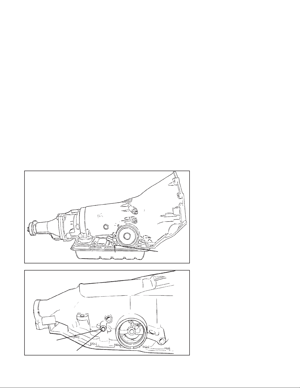
TH700-R4
Fourth gear oil pressure tap
Figure 2A
TH200-4R
Remove pipe plug and
install supplied pressure
switch here
Fourth gear oil pressure tap
Figure 2B
closed wire ties.
3. The wires should be kept out of the
way of the driver's and passenger's
hand and foot movement to avoid
snagging and possible disconnec tion.
4. Two long wires will route to the butt
end connectors installed in Step 2.
This may mean drilling a 5/16 inch
diameter hole in the floor or firewall
for the wires to pass through. Be
careful there are no obstructions
on the other side of the surface to
be drilled as they may become
damaged. Check for a suitable
existing hole first before drilling a
new hole.
STEP 4. Drill two 1/16" diameter holes
in the switch mounting surface, using
the bracket as a template for the
mounting hole spacing. From the wire
supplied in the kit, install a female
spade connector. Place this onto
terminal #3 of the switch. Route this
wire to a good ground. The ground
MUST be metal and should not have
Remove pipe plug
and install
supplied pressure
switch here
any paint in between the connector and
the metal. Cut ground wire to length
and install the tongue spade connector
on the end. Install spade connector to
ground.
STEP 5. Onto the remaining wire install
two spade connectors. Attach these
connectors to the terminals marked #1
and #2 on the switch. If there is no
existing hole in the firewall or floorboard
of the vehicle, drill a 5/16" hole. Feed
the two long wires through the supplied
rubber grommet then through the 5/16"
hole. Press the rubber grommet into
place. Route wires to the transmission
electrical connector. Cut the wires to
length and connect them to the two
butt connectors on the wire cut in step
2. See Figure 3. Make sure all wires
are secured and properly connected.
INSTALLATION TH200-4R AND
TH700-R4 FOUR SPEED
TRANSMISSIONS
STEP 1. Raise and support the vehicle
high enough to give yourself plenty of
room to work. Use jackstands or
ramps to support the vehicle safely.
Do not use a jack alone.
Locate the plastic electrical
connector on the driver's side of the
transmission. See Fig. 1. Locate the
fourth gear oil pressure tap on the
transmission case. See Figure 2A for
the TH700-R4 location and Figure 2B
for the TH200-4R tap location.
STEP 2. Remove the fourth gear oil
pressure tap plug. Install the supplied
pressure switch. On most applications
you will require a 45 degree elbow so
the switch will clear the exhaust pipe or
floor pan. Make sure that the switch is
not overtightened or cross threaded.
STEP 3. Install two female spade
connectors on the supplied wire. Install
them on the pressure switch terminals.
Run the wires over the top of the
transmission. Unplug the plastic
electrical connector from the case.
Locate pin "A". Cut the wire going to
pin "A" about 3-4" from the connector.
Strip the wires and place a butt end
connector on each end of the cut wire.
Connect the two pressure switch wires
to the other sides of the butt connectors.
(Polarity is not important.)
Note: If your transmission has a wire
Page 3

TH350C
3
2
1
TH700-R4
3
2
1
TH200-4R
3
2
1
ground
ground
ground
Figure 3
Figure 4
Figure 5
fourth gear
oil pressure
switch
tap
connectors
fourth gear
oil pressure
switch
tap
connectors
butt end
connectors
butt end
connectors
butt end
connectors
AB
from wire
harness
(+12 V)
B
A
from wire
harness
(+12 V)
A
B
from wire
harness
(+12 V)
on pin "D", cut the wire and ground the
end of the wire that goes to the plug.
Tape off the other end of the wire.
STEP 4. Decide on a mounting position
for the toggle switch, some place where
the driver has easy access to the
switch and the indicator light is not
visually obstructed. The most common
mounting locations are under the
dashboard or to the console (if
equipped). When choosing a mounting
location for the power switch keep in
mind a route for the wires from the
switch to the transmission. Keep in
mind the following cautions:
1. Do not route wires near the engine
or exhaust system. The wire's in sulation may melt or burn off, caus ing a short circuit.
2. Keep the wires from dangling be neath the car or the dashboard as
D
they may become tangled with se lector linkage or other moving parts.
Do not secure wires to any moving
parts. Secure wires to frame mem bers or other supports using en closed wire ties.
3. The wires should be kept out of the
way of the driver's and passenger's
hand and foot movement to avoid
snagging and possible disconnec tion.
4. Two long wires will route to the
wires installed in Step 3. This may
mean drilling a 5/16 inch diameter
hole in the floor or firewall for the
wires to pass through. Be careful
D
there are no obstructions on the
other side of the surface to be
drilled as they may become dam aged. Check fora suitable existing
hole first before drilling a new hole.
STEP 5. Drill two 1/16" diameter holes
in the switch mounting surface, using
the bracket as a template for the
mounting hole spacing. From the wire
supplied in the kit, install a female
Install run wireButt tap wire against stop
Fold and squeeze with pliers until latch locks
Figure 6
Page 4

spade connector. Place this onto
terminal #3 of the switch. Route this
wire to a good ground. The ground
MUST be metal and should not have
any paint in between the connector and
the metal. Cut ground wire to length
and install the tongue spade connector
on the end. Install spade connector to
ground.
STEP 6. Onto the supplied wire install
two spade connectors. Attach these
connectors to the terminals marked #1
and #2 on the switch. If there is no
existing hole in the firewall or floorboard
of the vehicle, drill a 5/16" hole. Feed
the two long wires through the supplied
rubber grommet then through the 5/16"
hole. Press the rubber grommet into
place. Route wires to the transmission
electrical connector. Connect the wires
from driver's control switch to the wires
from the oil switch using the remaining
tap connectors. See Figure 4 for the
TH700-R4 or Figure 5 for the TH200-
4R. Make sure all wires are secured
and properly connected.
OPERATION
When the toggle switch is lighted
the lockup clutch is disabled (except
in overdrive). With the light out the
lockup clutch functions normally. See
the trouble shooting guide below if
there are any problems.
TOOL LIST
Jackstands or wheel ramps
Small Punch or scribe
Funnel
Wirecutting, stripping and cripming tools
Pliers or vicegrips
3/8" drill motor
Needle nose pliers
5/16" drill bit
Small screwdriver
3/8" and 7/16" open end or fitting wrenches
TROUBLE SHOOTING GUIDE
MALFUNCTION
No converter clutch apply
PROBABLE CAUSE
Voltage not reaching solenoid. Plug not properly engaged.
Connectors not installed on proper terminals
Wires for solenoid pinched and grounded
Poor or broken electrical connection
Wire insulation stripped or bared causing short circuit
Faulty or damaged switch
PARTS LIST
1 Power switch with bracket
1 Oil pressure switch
2 Switch fittings
21' Wire
3 Splice connectors
2 Butt splices
6 Female spade connectors
1 Male spade connector
4 Wire wraps
Converter works despite switch
Indicator light does not work
Wrong wire clipped,"A" wire must be clipped
Short circuit or blown fuse in light circuit
Poor or broken electrical connections
Improper wire chosen to tap into electrical circuit
Bulb in switch broken or burned out
Wire from #1 switch terminal not properly grounded
 Loading...