

Page 1

Installation Instructions
Light Truck Megashifter
Part Number 80680
©2010, 2006, 2000 by B&M Racing & Performance Products
The B&M Light Truck Megashifter
shifter is designed to be used in most
light trucks equipped with most popular
three speed or four speed automatic
transmissions. Your B&M Megashifter
comes equipped with neutral safety and
backup light switches, transmission
brackets and levers and a five foot shift
cable. Optional shifter cables in 2
ft.(#80830), 3 ft.(#80831), 4 ft.(#80832), 8
ft.(#80834), 10 ft.(#80835) and 12 ft.
(#80836) are also available. To use the
B&M Light Truck Megashifter with the
Ford AOD transmissions you will need
the optional accessory kit #40496.To use
the B&M Light Truck Megashifter with
the GM 4L60E and 4L65E equipped with
a PRNDL switch you will need optional
accessory kit #75498 otherwise you can
use the GM bracket supplied.
This shifter has adjustable height
mounting brackets so that it can be installed at the best height for your truck.
Because the front and rear mounting
brackets can be adjusted separately, it
can also be install on an angled or sloping floor with the shifter mounted flat.
Please read the instructions and review the illustrations thoroughly before
beginning the installation.
The mechanical components of this
shifter are precision made and assembled at our factory. Any modification
or disassembly of these parts can cause
the shifter to malfunction and will void the
warranty. You should disassemble only
those items outlined in the instructions.
The vehicle should be about 2 feet off
the ground for ease of installation. Use
jack stands, wheel ramps or a vehicle lift.
Make sure the vehicle is firmly supported
before attempting to work on it.
IMPORTANT: If your vehicle is equipped
with a locking steering column, securing
the column lock lever in the engine compartment in the full up position will allow
the steering wheel to be locked and unlocked and the ignition key to be removed.
WARNING: This allows the steering wheel
to be locked WHENEVER the ignition key
is turned to the “lock” position WHILE
THE VEHICLE IS MOVING, OR AT ANY
OTHER TIME. Securing the steering column lock lever in any other position will
both PREVENT the steering wheel from
locking and the removal of the ignition
key.
INSTALLATION
NOTE: If you are installing this shifter with
a GM four speed automatic transmission, you must remove the blocker pin
and the two e-clips indicated in Figures
1 and 3. Removing this blocker pin gives
the shifter four forward positions rather
than three. For Ford AOD four speed
transmissions do not remove this blocker
pin and the two e-clips, since this transmission has only three forward positions. Also do not remove the blocker pin
and the two e-clips for three speed automatic transmissions.
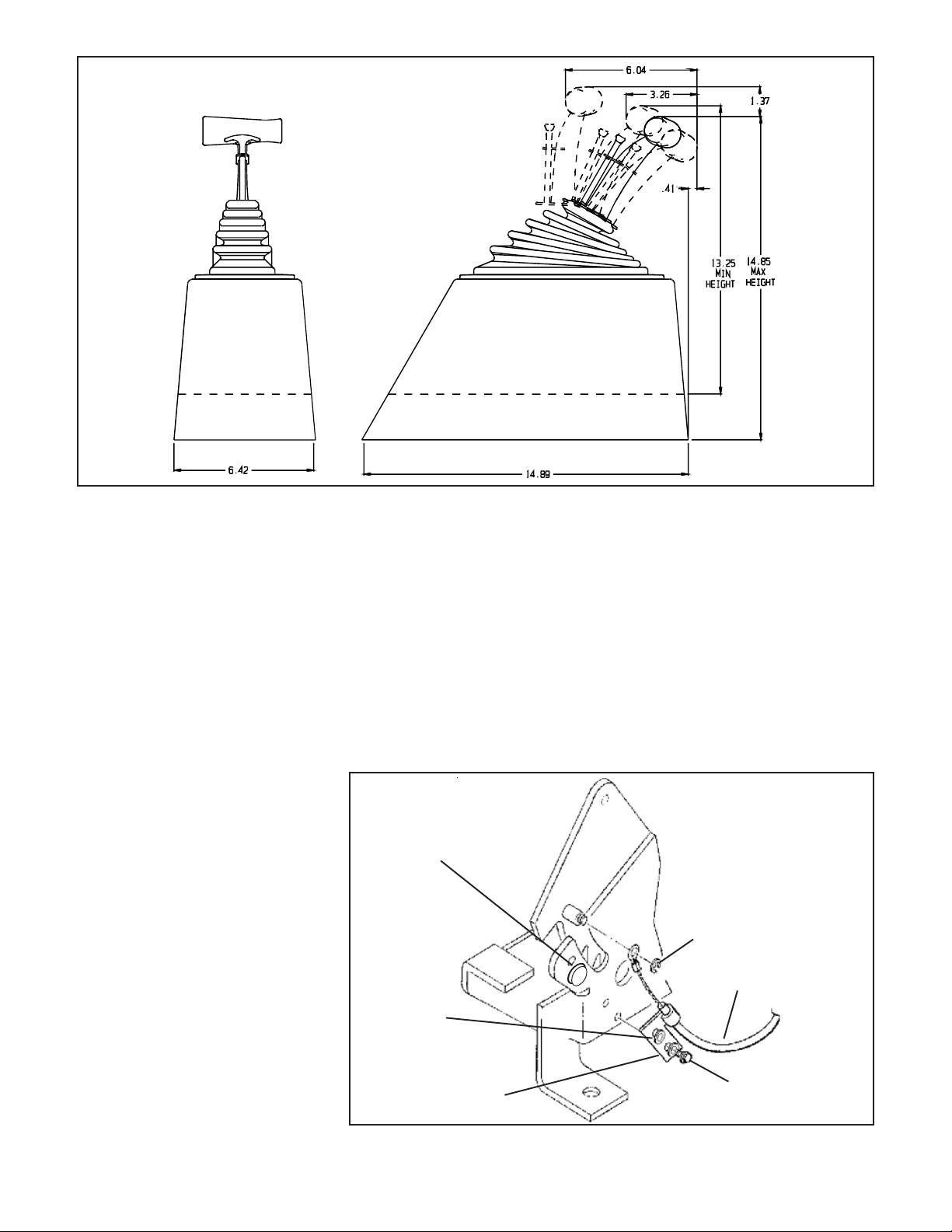
STEP 1. Locate the shifter on the floor of
the truck where you want it to be located.
The mounting brackets can mount the
basic shifter assembly 1-1/2" to 3-5/8"
above the floor. Figure 2 gives the dimension of the shifter, so be sure that there is
enough room where you will be mounting the shifter.
STEP 2. Remove the stock shift linkage;
Column Shifters: Remove all rods, le-
vers or cables from the column and the
transmission. Place the column shift lever in the Park position. Remove the pin
holding the shift lever in the column and
remove the lever assembly. If your vehicle is equipped with a locking steering
column, secure the column lock lever in
the full up position. WARNING: This allows the steering wheel to be locked and
the ignition key removed WHENEVER the
ignition key is turned to the Lock position
WHILE THE VEHICLE IS MOVING, OR AT
ANY OTHER TIME.
Console Shifters: Remove the shifter
mechanism from the console. Disconnect the rod or the cable from the transmission. Remove the cable bracket if
equipped. If there is a cable or linkage
from the console shifter or the transmission to the steering column lock, it must
be blocked in the Park position as described above.
NOTE: The shifter installation may require console modification or complete
console removal depending on the space
available in your vehicle.
STEP 3. Assemble the mounting
bracket as shown in Figure 1. Be sure
that the end plate with the wide slot on top
is to the front and that the top plate has the
three holes at the front. Assemble the
bracket with the four 1/4-20 x 3/4" screws
finger tight. Put flat washers on both sides
of the brackets and a lock washer under
the nut.
Pull the carpet away from the floorboard where the shifter mounting bracket
is to be located. Place the shifter on the
mounting bracket and slide the front and
rear brackets up or down to get the desired height for the shifter. Tighten the
four screws on the bracket. If the vehicle
has a bench type seat, move the seat to
the full forward position. With the stick
shifted to the rearmost gate position.
Locate the shifter for ease and convenience of operation (See Figure 2). Make
sure the trigger and the T-handle clear
the dash with the shifter in the Park position. Mark the position of four mounting
holes for the bracket assembly on the
floor.
STEP 4. Drill four 9/32" mounting holes
where marked. Temporarily mount the
shifter to the mounting bracket and bolt
the bracket to the floor. If the floor is not
flat, bend the tabs at the end of the front
and rear bracket. Mark the location for the
shifter cable hole in the floor. The hole will
be 1" inboard of the left front mounting
bracket to floor bolt and between 2-1/2"
Printed in U.S.A.
9500512-06
Page 2
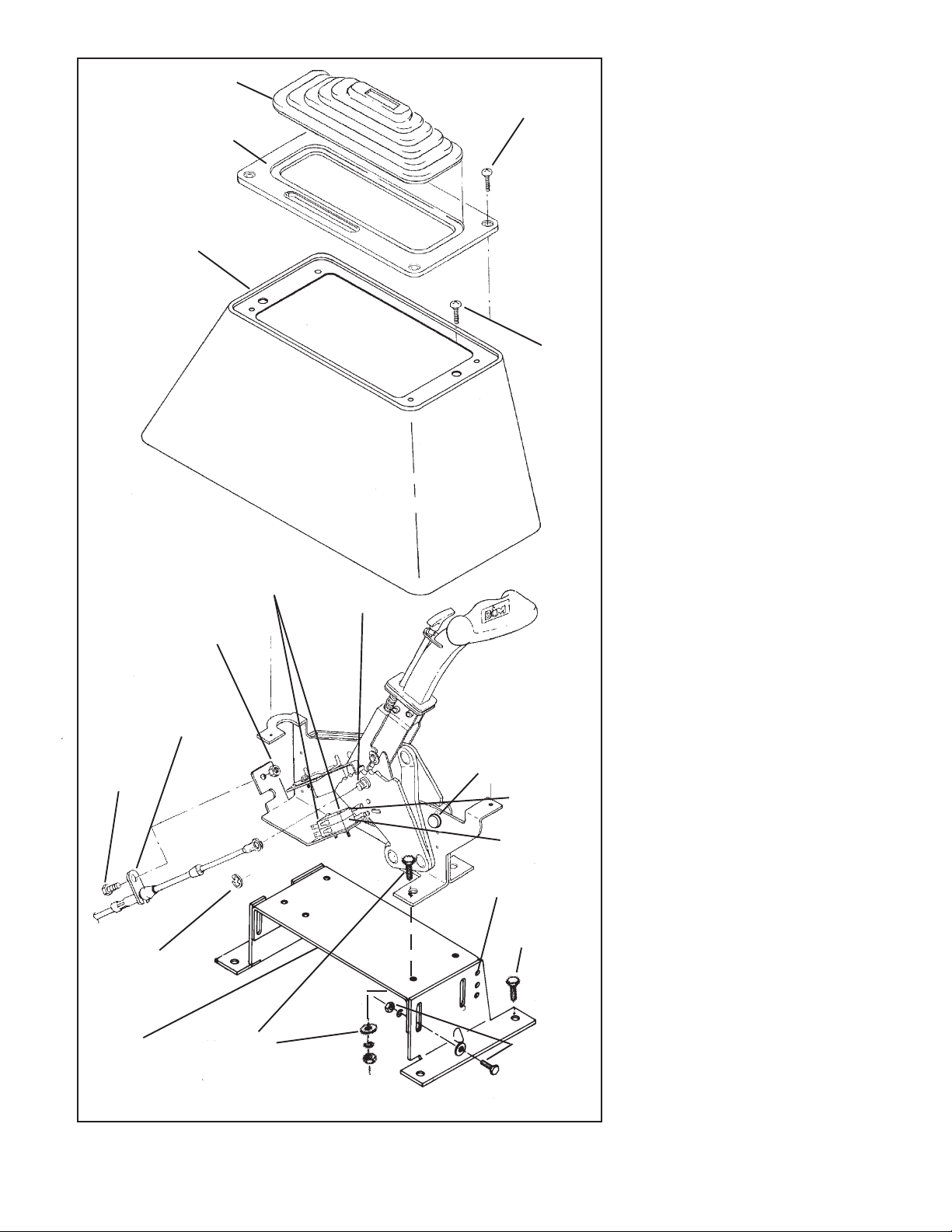
Cover plate
Tower
1/4" nut and
lockwasher
Cable attaching tab
goes on outside surface of shifter base
1/4-20 x 1/2"
screw
E-Clip
Mounting
base
1/4-20 x 3/4"
screw with flat
washer and lock
Boot
#4-40 x 1-1/4
screws, nuts and
lock washers
washer
Cable pin
Figure 1
10-32 x 3/4"
Pan head
10-24 x 1/2'
flat head
Remove this
blocker pin and
the two e-clips
GM four speed
transmissions
Backup light
switch
Neutral safety
switch
Locking
holes
1/4-20 x 1-1/2
full thread
screws
1/4-20 x 3/4"
screw with 2
flat washers
and lock
washer
2
for
and 3-1/2" ahead of this bolt. (The hole
will be 3-1/2" ahead if the bracket is at
maximum height and 2-1/2" ahead if the
bracket is adjusted to minimum height.
Drill or cut a 1-1/2" diameter cable hole in
the floorboard. NOTE: Some floorboards
are extremely thin and will not adequately
support the shifter mechanism when
bolted to the floor. For those vehicles we
recommend that you fabricate a stiffener
plate for additional strength.
STEP 5. Remove the mounting bracket
assembly. Tighten the four screws securely. At each end, drill a 1/4" hole through
one of the locking holes in each end of the
bracket into the top plate. Put a 1/4" screw
and a lock washer into each of these
holes to lock the bracket together. Attach
the shifter to the mounting bracket with
four 1/4-20 X 3/4" screws and lock washers.
STEP 6. Install (but do not secure) the
carpet back to it’s original position. Cut
holes in the carpet for the mounting holes
and cable. DO NOT use a drill bit to make
the holes in carpet.
STEP 7. Assemble neutral safety and
reverse light switches to the bracket using two #4-40 x 1" screws and nuts, as
shown in Figure 1. Beware, over tighten-
ing the switch attachment screws will
crack the switch housings. Install the
switch assembly on the shifter. To adjust
the switches, loosen the screws and
slide the switches in or out as required,
then retighten the screws.
STEP 8. Install the cable on the shifter
as shown in Figure 1. The cable attachment tab should be bolted to the outside
surface of the shifter base using a 1/4" x
1/2" hex screw, lock washer and nut.
Install the e-clip that secures the cable to
the cable pin.
STEP 9. Just before the final installation
of the shifter in the vehicle, attach the
indicator cable to the side of the shifter as
shown in Figure 3. The indicator cable
bracket is secured to the shifter mechanism with two #6 x 3/4" sheet metal
screws and #6 washers, the eyelet on the
end of the indicator cable is secured to
the cable pin by a supplied small e-clip.
STEP 10.Install the shifter mechanism
into the vehicle. Slide the shifter cable
through the carpet and the hole in floor.
Bolt the shifter down using four 1/4-20 x
1-1/2" full thread hex screws, nuts, lock
washers and flat washers. If the mounting bracket does not sit flat of the floor, the
tabs at the end of the mounting bracket
can be bent so that they will fit the floor.
ROUTE THE CABLE AS SHOWN IN FIGURE 4, AVOID SHARP BENDS WHICH
WILL KINK AND DAMAGE THE CABLE.
Use cable clamps or tie wraps to secure
the cable housing to the chassis to avoid
contact with hot engine or exhaust system.
STEP 11.Seal the hole where the cable
goes through the floorboards to prevent
Page 3
air or water leakage. A putty type sealer
can be used. For General Motors vehicles go to Step 12, for Ford vehicles got
to Step 17, for Chrysler vehicles go to
Step 23.
GENERAL MOTORS
STEP 10.If you have not already done so,
remove the stock selector lever nut and
the selector lever from the transmission.
Discard the stock lever and the stock
shifter linkage. Install the B&M selector
lever in position using the stock selector
lever nut (See Figure 5). Torque the nut to
23 lb.ft. The lever should move smoothly
from front to rear with a positive click in
each gear position.
STEP 11.Remove the two transmission
oil pan bolts from the middle of the left
side of the oil pan. Install the cable bracket
in position (See Figure 5). The bracket
must be installed with two spacers between the pan and the bracket. (If your
transmission is equipped with a cast
aluminum oil pan, these spacers should
be omitted. With a TH-400 with a cast
aluminum oil pan the cable bracket may
have to be modified.) Install the two 5/1618 x 1.00" bolts (Metric transmissions
use the two 8mm x 25mm bolts) supplied
and tighten to 12-13 lb.ft. Do not overtighten as this can damage the pan gasket.
STEP 12.Route the shifter cable according to Figure 4. Avoid kinks and sharp
bends and route the cable away from hot
engine or exhaust parts.
Remove the two rubber boots, one
large nut, and a large lockwas her from
the threaded end of the shifter cable.
Figure 2
Slide the end of the cable into the cable
bracket. Install the large nut and the
lockwasher loosely over the end of the
cable. Install the two rubber boots onto
the end of the cable. Install the swivel on
the threaded end of the cable and position it in the center of the threaded portion.
STEP 13.Move the transmission selector lever by hand to full rear position
(Low). Operate the shifter lever to the Low
gear position (ratcheted all the way back).
Adjust the large nuts on the cable so that
the swivel will slide into the front hole on
the selector lever. Tighten the large nuts
completely. Be sure that the swivel will
slide freely in and out of the hole in the
Remove this blocker pin
and the two e-clips for GM
four speed transmissions
Washer (2)
Bracket
Figure 3
selector lever. Note: The shifter will not
operate correctly unless the front hole
in the shift lever is used.
Leave the swivel out of the hole and
move the selector lever to Park, all the
way forward. Also move the shifter to the
Park position (all the way forward). Reinsert the swivel into the front hole in the
selector lever. Check to see that the swivel
will slide freely in and out of the front hole
in the selector lever in this position. If it
does not slip in freely, adjust the swivel
slightly until it will slip into the hole in the
lever.
Move the shifter back to the Low gear
position and check that the swivel will still
E-Clip
Indicator
cable
Sheet metal
screw (2)
3
Page 4

slide easily in and out of the front hole in
the selector lever. (If you do not use the
front hole in the lever, it will be impossible to correctly adjust the cable.) Operate the shifter through all the gear positions. Check to make sure the swivel will
slide in and out of the front selector lever
hole in each gear position. The shift cable
is now correctly adjusted. Install the cotter key supplied with the shifter into the
swivel and spread the key ends.
If you have a problem, DO NOT FORCE
THE SHIFTER, this will damage the cable,
the shifter or the transmission. Simply
start at the beginning and carefully check
all your steps.
STEP 14. On GM vehicles, the neutral
safety switch may be located on the
shifter (steering column or console), or it
may be a mechanical interlock in the
steering column that prevents the key
from turning to the Start position unless
the shifter is in the Park or Neutral position. Identify the type of neutral safety system you have. If the key will not turn to the
Start position unless the stock shifter is
in Park or Neutral, you have a mechanical
interlock type, otherwise you have a neutral safety switch type. If you have a neutral safety switch, locate the switch and
identify the neutral safety wires (engine
will not crank unless these wires are connected together). With either type, disconnect the battery ground cable to prevent
accidental shorts. If you have a neutral
safety switch, disconnect and extend both
wires from the GM switch to the switch on
the shifter. If you have a mechanical interlock cut the wire that goes from the Start
position on the ignition switch to the solenoid on the starter. This wire is usually a
10 or 12 gauge purple wire. Run wires
Figure 4
from both ends of the cut wire to the switch
on the shifter. Put slip on terminals on the
ends of the lengthened wire. Crimp the
terminals onto the wires using a crimping tool or pliers. Connect the wires to the
switch on the shifter. Tape the terminal
connections and all other connections to
prevent shorts. Reconnect the battery
ground cable, disconnect the coil wire
and set the parking brake. Check the
switch operation by attempting to start the
motor in each shifter position. The
starter must crank only when the
shifter is in the Park or Neutral position.
Adjust the switch if required. Reconnect
the coil wire. Go to Step 27.
FORD
STEP 15. If you have not already done so,
remove the nut and lockwasher holding
the downshift linkage onto the downshift
lever shaft. The downshift lever is the
outer lever on C-4, C-5, C-6 and AOD
transmissions. Pull the lever off the shaft
and allow the linkage to hang free. Remove and discard the stock shift linkage
rods. Some C-6 and all (late) C-4 and C5 transmissions have a neutral safety/
backup light switch on the transmission
F
Cable swivel
Cotter pin
(Use front hole)
R
C
GM lever
GM cable bracket
5/16 x 1" bolt and spacer
(Metric trans use M8 x 25 bolt)
7/16" nut
Figure 5
4
Spacer
Use these two holes for
TH-400 transmission. Use
other two holes for other
GM transmissions
Spacer
GM cable bracket (Trimming of bracket
required if used on cast aluminum pan)
Page 5

Ford C-4 and C-5
1/4 x 1-1/2" bolt,
lockwasher and nut
Ford lever
Cable swivel
Cotter pin
shift lever. If your transmission is so
equipped, remove the two bolts holding
the switch in place and slide it off the shift
shaft. Disconnect the switch at the factory
plug and discard it.
STEP 16. Install the B&M selector lever
(See Figure 6 or 7). Note: The B&M lever
must point downward for proper operation. If the stock shift lever on your transmission points down, you will have to
remove the lower part of the stock arm by
cutting it off to clear the B&M lever (See
Figure 6). Install the B&M selector lever
onto the shift shaft of the transmission.
Align the selector lever so when it points
straight down it travels equal arcs in both
directions from the center, then tighten
the 1/4"-20 x 1 1/2" pinch bolt and nut. The
lever should travel smoothly from front to
back with a positive click in each gear
position. Make sure the O-ring is in position on the downshift shaft and install the
downshift lever in position on the shaft.
Install the lockwasher and the nut and
tighten securely. The downshift lever must
operate smoothly. Reconnect the downshift linkage.
STEP 17. Cable bracket installation:
AOD: Instructions for the AOD are in-
cluded with the optional installation kit
#40496.
C-4, C-5: Remove the two lower bolts
from the rear servo cover. Install the cable
bracket in position (See Figure 6). Install
the two servo cover bolts as removed and
tighten to 12-13 lb.ft. Do not overtighten
as this can distort the servo cover.
C-6: Remove the two transmission oil
pan bolts from the left rear corner of the
oil pan. Install the cable bracket in position (See Figure 7) with two spacers between the pan and the bracket. (If your
transmission is equipped with a cast
aluminum oil pan, these spacers can be
omitted.) Install the two 5/16-18 x 1.00"
7/16" nut
C-4 cable bracket
Figure 6
Ford C-6
1/4" x 1-1/2" bolt,
lockwahsher, nut
Ford
lever
Cable swivel
Cotter pin
5/16" x 1" bolt
and spacer
Figure 7
bolts supplied and tighten to 12-13 lb.ft.
Do not overtighten as this can damage
the pan gasket.
STEP 18.Route the shifter cable according to Figure 4. Avoid kinks and sharp
bends and route the cable away from hot
engine or exhaust parts.
Remove the two rubber boots, one
large nut, and a large lockwasher from
the threaded end of the shifter cable.
Slide the end of the cable into the cable
bracket. Install the large nut and the
lockwasher loosely over the end of the
cable. Install the two rubber boots onto
the end of the cable. Install the swivel on
the threaded end of the cable and position it in the center of the threaded portion.
STEP 19.Move the transmission selec-
Remove shaded
portion of lever
C-6 cable
bracket
7/16" nut
tor lever by hand to full rear position
(Low). Place the shifter lever to the Low
gear position (ratcheted all the way back).
Adjust the large nuts on the cable so that
the swivel will slide into the hole on the
selector lever. Tighten the large nuts completely. Be sure that the swivel will slide
freely in and out of the hole in the selector
lever.
With the swivel in the selector lever,
move the shifter to Park position, as far
forward as the shifter will go without forcing it. (The shifter has further travel that
is used to reach the GM Park position but
is not used on Ford transmissions. Trying to force the cable will damage the
cable.) The shift lever on the transmission should be all the way forward. Check
5
Page 6

Chrysler A-727 and A-904
7/16" nut
Chrysler cable
bracket
5/16" x 1" bolt and spacer
Figure 8
to see that the swivel will slide freely in
and out of the hole in the lever in this
position. If it does not slip in freely, adjust
the swivel slightly until it will slip into the
hole in the lever in both the Low and the
Park positions. Operate the shifter
through all the gear positions. Check to
make sure the swivel will slide in and out
of the selector lever hole in each gear
position. Install the cotter key supplied
with the shifter into the swivel and spread
the key ends.
If you have a problem, DO NOT FORCE
THE SHIFTER, this will damage the cable,
the shifter or the transmission. Simply
start at the beginning and carefully check
all your steps.
IMPORTANT: Do not froce the shifter to
Figure 9
1/4" x 1-1/2" bolt,
lockwasher, nut
Chrysler lever
Cable swivel
Cotter pin
over travel into the Park position. This will
move the shifter into GM Park position
and will damage the cable or the transmission.
STEP 20. On Ford vehicles, the neutral
safety/backup light switch is located on
the transmission (or on the steering column on some early vehicles). If the vehicle has an AOD transmission the neutral safety/backup light switches on the
B&M shifter will
safety/backup light switch on AOD transmissions will continue to function normally.
On the C-4 and C-5 transmissions it is
necessary to completely remove the
stock neutral safety/backup light switch
in order to install the B&M transmis-
NOT be used. The neutral
6
sion shift lever. On C-4, C-5 and C-6
transmissions, it will be necessary to
hook up the neutral safety/backup light
switches on the B&M Megashifter.
Locate and identify the neutral safety
(the engine will not crank unless these
wires are connected together), and the
reverse light wires. Disconnect the
battery ground cable before beginning
to wire the neutral safety and reverse
light switches. Reroute the wires to the
B&M Megashifter. Strip 1/4" of insulation off the wires and install the
supplied slip-on terminals. Crimp the
terminals onto the wires using a
crimping tool or pliers. Connect the
neutral safety wires to the LOWER
switch and the reverse light wires to
the UPPER switch (See Figure 1) . Tape
the terminal connections to prevent
shorts. Reconnect the battery ground
cable, disconnect the coil wire and set
the parking brake. Check the switch
operation by attempting to start the
motor in each shifter position. The
starter must crank only when the
shifter is in the Park or Neutral
position. Check the backup light
operation when the shifter is shifted to
the Reverse position. Adjust the
switches if required. Reconnect the
coil wire. Go to Step 29.
CHRYSLER
STEP 21. If you have not already done
so, loosen the pinch bolt on the throttle
lever on the transmission. This is the
lever on the small diameter shaft. Pry
the lever off with a screwdriver and
allow the linkage to hang free. Remove
and discard the stock shift lever and
the stock shift linkage. Install the B&M
selector lever in position and tighten
the pinch bolt securely (See Figure 8).
Make sure the lever is not pushed
down so far as to touch the transmission case. This will cause the lever to
bind on the case. The lever should
travel smoothly from front to back with
a positive click in each gear position.
Install the stock throttle lever in
position on the small diameter shaft
as removed and tighten the pinch bolt
securely. The throttle lever must
operate smoothly.
STEP 22. Remove the two transmission
oil pan bolts directly below the shift lever.
Install the cable bracket in position (See
Figure 8) with two spacers between the
pan and the bracket. (If your transmission is equipped with a cast aluminum
oil pan these spacers can be omitted.)
Install the two 5/16-18 x 1.00" pan bolts
supplied and tighten to 12-13 lb.ft. Do not
overtighten as this can damage the pan
gasket.
STEP 23.Route the shifter cable according to Figure 4. Avoid kinks and sharp
bends and route the cable away from hot
Page 7

engine or exhaust parts.
Remove the two rubber boots, one
large nut, and a large lockwasher from
the threaded end of the shifter cable.
Slide the end of the cable into the cable
bracket. Install the large nut and the
lockwasher loosely over the end of the
cable. Install the two rubber boots onto
the end of the cable. Install the swivel on
the threaded end of the cable and position it in the center of the threaded portion.
STEP 24.Move the transmission selector lever by hand to full forward position
(Low). Place the shifter lever to the Low
gear position (ratcheted all the way back).
Adjust the large nuts on the cable so that
the swivel will slide into the hole on the
selector lever. Tighten the large nuts completely. Be sure that the swivel will slide
freely in and out of the hole in the selector
lever.
With the swivel in the selector lever,
move the shifter to the Park position, as
far forward as the shifter will go without
forcing it. (The shifter has further travel
that is used to reach the GM Park position
but is not used on Chrysler transmissions. Trying to force the shifter will damage the cable.) The shift lever on the
transmission should be all the way back.
Check to see that the swivel will slide
freely in and out of the hole in the lever in
this position. If it does not slip in freely,
adjust the swivel slightly until it will slip
into the hole in the lever in both the Low
and the Park positions. Operate the
shifter through all the gear positions.
Check to make sure the swivel will slide
in and out of the selector lever hole in
each gear position. Install the cotter key
supplied with the shifter into the swivel
and spread the key ends.
If you have a problem, DO NOT FORCE
THE SHIFTER, this will damage the cable,
the shifter or the transmission. Simply
start at the beginning and carefully check
all your steps.
IMPORTANT: Do not force the shifter to
over travel into the Park position. This will
move the shifter into the GM Park position
and will damage the cable or the transmission.
STEP 25. Check the operation of the
throttle linkage again. The linkage must
operate smoothly with no bind. All transmissions using automatic valve bodies
must have the throttle linkage connected
and operating or transmission damage
will result.
STEP 26. Neutral Safety/backup light
switch.
’66-’68: The neutral safety switch will
continue to function normally. It will not be
necessary to hook up the neutral safety
switch wires on the shifter. Disconnect
the battery ground cable before wiring the
backup light switch. Locate the original
backup light switch on the steering column or the console shifter. Run these
wires to the top switch on the B&M
Megashifter (See Figure 1). Reconnect
the ground wire and check the light for
proper operation. Adjust the switches on
the shifter if required.
’69 and Later: The neutral safety/backup
switch is located on the transmission
and will continue to function normally. It
will not be necessary to connect any wires
to the switches on the shifter.
STEP 27. Check the operation of the
throttle linkage again. Linkage must operate smoothly with no bind. All transmissions using automatic valve bodies must
have the throttle linkage connected and
operating or transmission damage will
result.
STEP 28. Neutral safety/backup light
switch
’66-’68: The neutral safety switch will
continue to function normally. It will not be
necessary to hook up the neutral safety
switch wires on the shifter. Disconnect
the battery ground cable before wiring the
backup light switch. Locate the original
backup light switch on the steering column or the console shifter. Run these
wires to the top switch on the B&M Light
Truck Megashifter (See Figure 1). Reconnect the ground wire and check the
light for proper operation. Adjust the
switches on the shifter if required.
’69 and Later: The neutral safety/backup
switch is located on the transmission
IMPORTANT
Before installing the T-handle onto
the shifter put a little grease on the
threads of the stick. The aluminum of
the T-handle may gall on the threads
of the stick and make it impossible to
remove the T-handle from the stick. If
this occurs it can cause the stick to
break if you use excessive force while
attempting to remove the T-handle
from the stick.
and will continue to function normally. It
will not be necessary to connect any wires
to the switches on the shifter.
STEP 29. Place the tower over the shifter
mechanism until the bottom edge of the
tower touches the floor. Put the shifter
cover and the indicator cable through the
opening in the top of the tower. Hold the
tower level to the shifter with the bottom
of the tower touching the highest surface
on the floor it will come into contact with
(See Figure 9). Use a ruler to measure
the distance X from the underside of the
tower to the tower mounting brackets on
the shifter mechanism.
STEP 30. Set a pair of dividers at the
distance X, measured in step 29. Hold
the tower level to the shifter mechanism
with the bottom of the tower touching the
highest surface on the floor it will come
into contact with. Holding the tower in
position, place one leg of the divider
against the floor while the other touches
the tower (See Figure 9). Using the divid-
ers, scribe a line around the tower that
follows the contour of the floorboard.
Remove the tower and trim at the scribe
line using tin snips. Once the tower is
properly trimmed, install it using two flat
head sheet metal screws. The indicator
cable should be routed out the top of the
tower on the right side while the tower is
being installed.
STEP 31. Install the indicator light bulb in
its socket on the shifter cover plate. Run
a length of wire from the vehicle’s instrument light circuit to one of the wires.
Connect the other wire to a good chassis
ground. A shifter mounting bolt should be
satisfactory.
STEP 32. Snap the shift position window
into the cover plate. The window snaps in
from the top with tabs inserting into the
slots at either end of the window opening.
Place the shifter in the Park position then
remove the T-Handle from the shifter.
Place the cover plate over the stick and
onto the top of the tower. Route the indicator cable as shown in Figure 10. (If the
cable is not routed this way, the indicator
may bind. Run the shifter through all of
the gears to check the operation of the
indicator. If the indicator needs adjustment, loosen the screws holding the indicator cable clamp to the cover plate and
slide the cable bracket to adjust the indicator position. (Re-tighten these screws
carefully since they are threaded into the
plastic.) Attach the cover plate to the tower
with four Phillips head screws.
STEP 33. Slide the boot over the stick
and install it into the cover plate. After the
TOOL LIST
1 Common screwdriver
1 Phillips screwdriver
1 1/4" wrench or socket
2 7/16" wrench or socket
1 1/2" wrench
2 11/16" wrench
1 13mm wrench
(Metric transmissions)
1 Drill motor
1 9/32" drill bit
1 1/2" drill bit or holesaw
1 0-50 lb.ft. torque wrench
1 File
1 Tin snips
1 Hack saw
1 Wire stripper
1 Wire crimper
1 Pliers
1 Ruler
1 Dividers
A/R Electrical tape
A/R Tie wraps
(to secure cable)
2/4 Jack stands
7
Page 8

boot is installed in the cover plate and into
the stick, install the T-Handle and the jam
nut. Tighten the jam nut when the handle
is properly oriented.
OPERATION
The B&M Light Truck Megashifter nor-
mally functions as a straight gate detent
shifter from Park to Reverse to Neutral to
Drive and as a ratchet shifter from Neutral
to all the forward gears. Refer to the
following instructions for proper operation:
STRAIGHT GATE MODE: With the trigger
in the upper position, the shifter functions
in the STRAIGHT GATE mode. The handle
travels in a direct line forward and backward from PARK to DRIVE. The trigger
must be raised up to clear the stop gates
while going through the gear positions.
RATCHET SHIFT MODE: The RATCHET
SHIFT mode allows firm, positive nomiss upshifts and downshifts through all
positions from 1 (Low gear) to Neutral. To
switch from STRAIGHT GATE to
RATCHET operation, first operate the
shifter to the Drive position. The trigger
will snap down approximately 3/4". The
shifter is now in the RATCHET MODE,
Drive gear position. The shifter will only
operate in the RATCHET MODE between
Neutral and First, it will not ratchet to
Reverse or Park. This is done to prevent
accidental shifting into Reverse.
SHIFTING IN THE RATCHET MODE: Move
the shift handle forward or backward with
a quick firm action until it hits the internal
stops, and allow it to spring return to the
center position. The shifter is now ready
for the next shift.
To switch the shifter from RATCHET
MODE back to the STRAIGHT GATE
MODE, operate the shifter to the Drive
gear position, pull up firmly on the trigger
to engage the STRAIGHT GATE MODE
and move the handle forward to Neutral,
Reverse and Park.
REMEMBER: To switch from the
STRAIGHT GATE MODE to the RATCHET
MODE or from RATCHET MODE to
STRAIGHT GATE MODE you must be in
the Drive gear position. Refer to the shift
Route indicator cable around
front of backing plate and over
Figure 10
indicator gear position.
SPECIAL NOTE: If the instructions for operating your shifter seem complicated,
DO NOT BECOME ALARMED. You will
find that in actual use the shifter will be
extremely easy to operate after a minimal
amount of experience. Caution: The
shifter is an important controlling mechanism of your vehicle and can create serious driving hazards when any part is
loose, missing or misadjusted. After you
have installed your B&M Light Truck
Megashifter in the vehicle, we recommend you review the instructions to assure complete and proper installation.
CHECK LIST
__ Locking steering column lever is permanently fastened
in the full up position. Step 2.
__ Shifter is convenient to reach and has ample room for
your hand in both park and low gear. Step 3.
__ Carpet covers floorboard holes. Step 6.
__ Cable is securely fastened to the shifter and held with
E-clip. Step 8
__ Shifter is securely mounted to floorboard. Step 10.
__ Shifter cable is clear of exhaust system, engine and any
moving parts. Step 10.
__ Throttle lever and shift lever are tight on transmission.
GM step 12, Ford Step 17, Chrysler Step 23.
__ Oil pan bolts are tightened to 12-13 lb.ft. GM Step 13,
Ford Step 19, Chrysler Step 24.
__ Shifter is properly adjusted. Cable boots are installed,
cable nuts are tightened and swivel is secured with
cotter key. GM Step 15, Ford Step 21, Chrysler Step 26.
__ The Neutral safety and Reverse light switches are
connected and properly adjusted to prevent engine
starts in drive gears and Reverse. GM Step 16, Ford Step
22, Chry Step 26.
__ There is no debris in the shifter mechanism.
__ Tower is trimmed and securely held with two screws.
Step 29.
__ Cover installed and shift position indicator operating
properly. Step 31.
__ Shifter moves freely in all positions as described in
Shifter Operation.
__ If your shifter is not working properly do not attempt to
drive your car. Make sure you have followed all instruc-
tions. If the shifter is broken or defective return it to your
B&M dealer.
WARNING
PERIODIC INSPECTION AND MAINTENANCE OF YOUR SHIFTER IS RECOMMENDED TO ENSURE THAT THE
MECHANISM IS WELL LUBRICATED, FREE FROM DIRT OR RUST AND THAT THE CABLE IS PROPERLY ADJUSTED.
LACK OF MAINTENANCE COULD RESULT IN A FAILURE INCLUDING A FAILURE OF THE REVERSE LOCKOUT SAFETY
FEATURE.
8
 Loading...