

Page 1

Installation Instructions
Launch Control
(see www.bmracing.com for the latest technical product information)
Part Number 46075
© 2007, 2002 by B&M Racing and Performance Products
This Launch Control must be
installed according to these
instructions for safe operation. The
unit can be used in either the front
wheel part of the brake system or the
rear wheel part of the brake system
of a passenger car or light duty truck.
Install the launch control in the rear
brake system only for use as a hill
holder system on the street.
The B&M Launch Control is a
standard design with one connection
from the master cylinder and one
connection to the brakes.
WARNING: The B&M Launch
Control is designed primarily for use
on high performance vehicles used in
drag racing. It is for short term use
(60 seconds maximum) to lock the
wheels while staging the vehicle for
drag racing. It is not intended for use
as a long term brake holding device.
It should only be used on passenger
cars and light trucks (3/4 ton or less)
using a standard hydraulic brake
system that is in good safe operating
condition. If your vehicle is equipped
with a dual diagonal braking system
(the left front is connected to the
right rear and the right front is
connected to the left rear; common
to front drive imports), two launch
controls must be utilized. The B&M
Launch Control should never be used
as a temporary brake holding device
in place of a parking brake or in place
of a driver depressing the brake pedal.
IMPORTANT: Read and fully
understand these instructions before
installing the B&M Launch Control.
Note that these instructions contain
warnings that must be observed in
order to reduce the risk of improper
installation that could make the
vehicle unsafe and result in possible
serious injury. If you are not
experienced or qualified at doing this
type of installation, we strongly
recommend that you have the B&M
Launch Control installed by a qualified
and certified automotive mechanic.
Do not cut or attempt to flare steel
tubing. Do not use copper tubing. Use
a tube bender when bending the
tubing to avoid crushing the tube. Pre
assembled steel braided BRAKE
hoses may be an acceptable
substitute for steel lines in high
performance applications.
INSTALLATION NOTES
On rear wheel drive applications, the
solenoid valve can be installed in the
front wheel brake system as a staging
device for drag racing and in the rear
wheel brake system for short term use
as a hill holder (60 seconds
maximum). On front wheel drive
applications, the solenoid valve(s)
should be mounted in the rear braking
system(s) for use either as a staging
device or hill-holder (60 seconds
maximum), The solenoid valve does
not interfere with normal operation of
the brakes or with safety regulations
when installed according to these
instructions.
The brake light system on the rear
of the vehicle must operate when any
part of the brake system is
pressurized. A hydraulic pressure
brake light switch must be installed in
the system if the launch control valve
defeats the operation of the stock
brake light switch. See the electrical
section for details.
The launch control valve must be
mounted to a rigid surface to prevent
vibrations that could cause failures of
the joints or lines· The firewall is a
good mounting location. Keep the
valve and the brake lines away from
the heat of the exhaust system.
Two basic types of master
cylinders have been used on
production cars, single master
cylinder and dual master cylinder·
Dual master cylinders have been
required on all production cars built
since approximately 1970, earlier cars
have single master cylinders. The dual
master cylinders have the brake fluid
reservoir divided into two separate
sections while single master cylinders
have a single compartment reservoir.
SOME CARS (MOSTLY FRONT
WHEEL DRIVE) HAVE
DIAGONALLY SPLIT SYSTEMS
WHERE THE RIGHT FRONT
Printed in the USA
9500553-05
Page 2
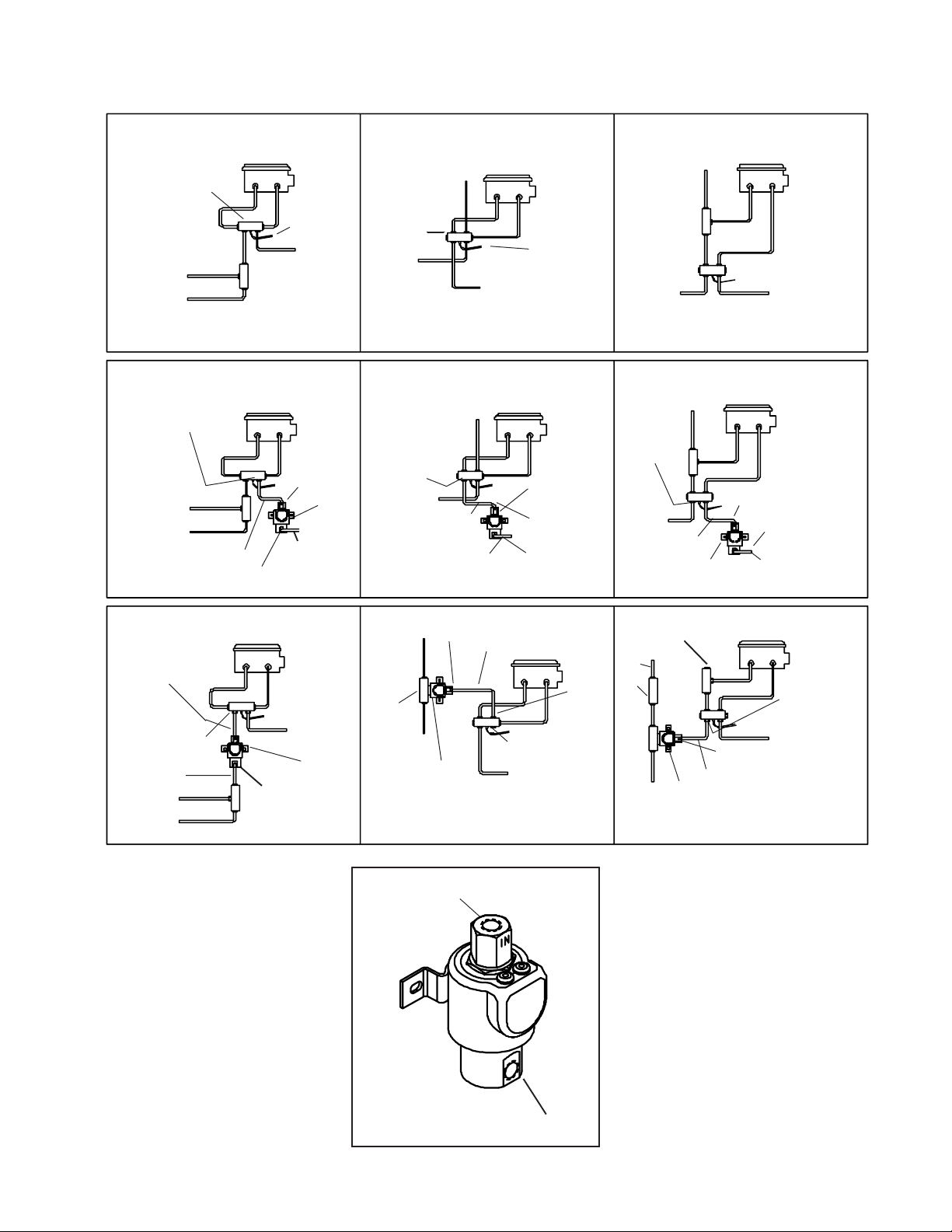
SYSTEM A
Dual Master Cylinder
SYSTEM B
Dual Master Cylinder
SYSTEM C
Dual Master Cylinder
Master
Cylinder
Pressure differential
switch block
Wire to
warning light
To rear
brakesTo left front brake
To right front brake
Distribution block
TYPICAL STOCK SYSTEMFRONT BRAKE INSTALLATIONS REAR BRAKE INSTALLATIONS
New
line
connector
Cylinder
Male
Master
Connector
To rear
brakes
The size of this
tube nut determines the size
of the new line
To left front brake
To right front brake
Male
Launch
control
solenoid
valve
Pressure
differential
switch block
To left front
brake
The size of this
tube nut determines the size
of the new line
To left front
brake
To right
front brake
New line
To right
front brake
To rear
brakes
Master
Cylinder
To rear
brakes
Master
Cylinder
May require a new
line to reach valve.
Wire to
warning light
Launch control
solenoid valve
Male
connector
Use a union.
Distribution
block
Pressure
differential switch
block
To right
front brake
To left front
The size of this
tube nut determines the size
of the new line
To right
front brake
Launch control
solenoid valve
To left front
brake
brake
New line
Master
Cylinder
warning light
Master
Cylinder
Male
connector
To rear
Wire to
brakes
To rear
brakes
May require a new
line to reach valve.
Use a union.
Master
The size of this
tube nut determines the size
of the new line
Original line
redirected to
solenoid valve
To left front brake
To right front brake
New
line
Cylinder
connector
Male
To rear
brakes
Launch
control
solenoid
valve
BRAKE AND THE LEFT REAR
BRAKE ARE ON ONE CIRCUIT
WITH THE LEFT FRONT BRAKE
AND RIGHT REAR BRAKE ARE ON
THE SECOND CIRCUIT. FOR
THESE SYSTEMS, IT IS
RECOMMENDED THAT TWO
LAUNCH CONTROLS BE UTILIZED
, ONE IN EACH SYSTEM.
Illustrations are given for the hydraulic
portion of six typical single and dual
master cylinder brake systems. These
represent the hydraulic system of
most domestic and import vehicles.
The electrical section of the
To right
front brake
Male
branch
tee fitting
To left front
brake
Male
connector
Launch
control
solenoid
valve
From master
cylinder
New
line
Master
Cylinder
Steel plug
straight
thread
To rear
brakes
brakes
To
The size
of this
tube nut
determines
the size
of the
new line
Left
front
original
line
Union
Male
branch
tee
fitting
To right
front brake
Steel plug
straight
thread
Launch control
solenoid valve
New line
Master
Cylinder
The size of this
tube nut determines the size
of the new line
To rear
Male
connector
Note: Connect left front original line to male
branch tee fitting. If original line doesn’t reach,
connect new line with union as shown,
brakes
instructions is the same for all
systems. Read the instructions
thoroughly and identify the additional
brake line and fittings that you will
require. These lines and fittings are
available for most popular vehicles. In
order to determine the correct fittings
required, a tube nut gauge is included
with this kit. The locations to check
the fittings are shown on the
illustrations for the different types of
brake systems.
INSTALLATION
Step 1. Measure the stock tube nut
at the position indicated on the
2
Page 3

SYSTEM D
Single Master Cylinder
To right
front brake
To left front
brake
Distribution
block
Distribution
To right
front brake
New line
To left front
brake
The size of this
tube nut determines the size
of the new line
New line
block
Launch control
solenoid valve
Master
Cylinder
To rear
brakes
Master
Cylinder
Male
connector
To rear
brakes
May require a new
line to reach valve.
Use a union.
SYSTEM E
Single Master Cylinder
To right
front brake
To rear
brakes
Distribution
block
To left front
Male
connector
To rear
brakes
Launch
control
solenoid
valve
New line
The size of this
tube nut determines the size
of the new line
brake
To right
front brake
To left front
brake
Master
Cylinder
Master
Cylinder
SYSTEM F
Metric Diagonal Braking System
To right
front brake
To left rear
To right
front brake
Metric to
SAE adapter
To left rear
brake
brake
Distribution
block
Distribution
block
New
lines
Master
Cylinder
To left front
brake
To right
rear brake
Master
Cylinder
To left front
brake
Metric to
SAE adapter
To right
rear brake
Master
connector
To right
front brake
To left front
brake
Steel plug
straight thread
Male
The size of this
tube nut determines the size
of the new line
New line
Cylinder
Launch control
solenoid valve
Male
branch
tee
fitting
To rear
brakes
drawing that matches your brake
system. The size of the tube nut
measured across the flats with the
gauge indicates the size of the female
threads in the distribution block or the
differential pressure switch block. You
must use two female fittings for the
launch control solenoid valve, one for
the inlet and one for the outlet. These
fittings will have a male 1/8" NPT
tapered pipe thread on one side. If a
male connector is called for on the
diagram of your sys-tem, you want a
male connector with the 1/8" NPT pipe
thread on one end and a flare fitting
Launch
control
solenoid
valve
Steel plug
straight thread
The size of this
tube nut determines the size
of the new line
Master
Cylinder
To right
front brake
Male
branch
tee
fitting
To left front
brake
To rear
brakes
Male
connector
with female threads the same size as
the threads that was measured with
the gauge. Where a male branch tee
is called for on the diagram, you want
a tee fitting with a 1/8" NPT male pipe
thread on one end and flare fittings
on the other two sides of the tee.
Step 2. Install the male connectors
and/or male branch tees in the correct
ports of the solenoid valve. In all cases
the Master Cylinder connects to port
labeled “IN” and the line to the brakes
connects to the port marked “OUT”.
Mount the valve in a position that
locates the connectors close to the
line to which they will be connected.
The mounting position of the valve is
not important. Using the holes in the
bracket of the valve as a guide, drill
two .185" (No. 13 drill) holes for
mounting.
Step 3. Install a new length of steel
brake line tubing in the specified
location and reroute the existing brake
lines. When bending brake line use a
tube bender to avoid crushing the
tubing. If an existing brake line must
be lengthened, a flare union must be
used. Where there is an unused port
in the distribution block or pressure
differential switch block use a steel
plug designed for flare fittings. These
plugs, like all of the tube nuts used in
the system, have straight machine
threads, not tapered pipe threads. Do
not attempt to force a tapered pipe
plug or fitting into a port with straight
threads.
ELECTRICAL INSTALLATION
Make sure that all electrical
connections are properly joined
together by either soldering the
con-nection or by using a crimp-on
3
Page 4

To supplied or
other switch
insulated connector. All soldered
connections should be wrapped with
plastic electrical tape. All wires should
be as short and direct as possible, but
not short enough to put any tension
on the wires. Electrical wires should
not be under tension even when the
engine and transmission move on the
their mounts.
Step 1. Disconnect the negative
battery cable.
Step 2. A momentary push button
switch is supplied and may be
mounted in any convenient position.
You may want to use the B&M THandle with push button (#80659
chrome or #80658 brushed aluminum)
or the push button knob (#46112),
These knobs and T-Handles will fit
most S.A.E. sizes of shifter stick
threads.
Step 3. Run a length of 18 gauge wire
from the end of the switch cable to
the solenoid valve(s). At the solenoid
valve(s) splice the newly installed wire
to one lead of the solenoid(s), ground
the other solenoid lead(s).
Step 4. Connect one end of the fuse
holder to a switched ignition terminal.
Run a length of 18 gauge wire from
the other end of the fuse holder to the
other wire of the switch cable. Splice
this wire at both ends.
Step 6. Connect the battery. The
solenoid valve(s) should operate
when the push button is depressed.
If the fuse blows out there is a short
circuit. Check all of the splices and
connections to be sure they are
insulated and that there are no short
circuits.
Step 7. Apply the brakes hard, push
and hold the launch control button and
release the brakes. Have someone
check to see if the brake lights remain
on. If the lights go out it will be
necessary to add an additional
hydraulic brake light switch. The
switch should be installed on the
brake side of the solenoid valve, as
shown in the illustration. The two
terminals of the new brake light switch
should be wired in parallel with the
existing brake light switch.
OPERATION
Pressing and holding the launch
control push button switch energizes
the solenoid valve. When the brake
pedal is pushed the hydraulic
pressure applies all four brakes. When
the brake pedal is released the
pressure is retained the solenoid valve
on the wheels that are controlled by
the launch control, while the pressure
is released on the other wheels. When
the push button is released the brakes
that were held on by the launch control
are released and the vehicle can
accelerate. After the installation, but
before driving the vehicle, check the
brake system thoroughly for leaks and
be sure that you have a solid brake
pedal. Apply the launch control
several times and be sure that the
wheels that are supposed to be locked
are locked and that the brakes are free
when the launch control is released.
After the installation has been
completed bleed the entire brake
system thoroughly to eliminate all air
in the system. Check all connections
for leakage under pressure and be
sure you have a hard brake pedal, not
a soft pedal. Replace any brake fluid
lost by the installation or by bleeding
with heavy duty brake fluid marked
DOT 3 or DOT 4.
For most automatic transmission
shifters we recommend that you use
the B&M T-Handle with push button
(#80659 chrome or #80658 brushed
aluminum) or the push button knob
(#46112). These knobs and THandles will fit most sizes of stick
threads. B&M also offers remote
buttons with spiral cord #46003 and
#46013.
4
 Loading...