

Page 1
Torque Converter
Installation Instructions for
General Motors TH700-R4 (4L60), 4L60E,
TH200-4R and TH200C
Part Nos. 70415, 70416, 70417, 70418, 70419, 70420, 70422, 70425 , 70426, 70440 & 70441
(C) B&M Racing & Performance Products 1996, 1999, 2004
Congratulations! You have just purchased the best performing and highest
quality torque converter available. We
have endeavored to make these installation instructions as clear and complete
as possible. Anyone with a minimum of
mechanical experience should be capable of installing a torque converter
using proper tools and following the instructions. IMPORTANT: Read the instructions completely before beginning
the installation so you can familiarize
yourself with the procedures.
APPLICATIONS
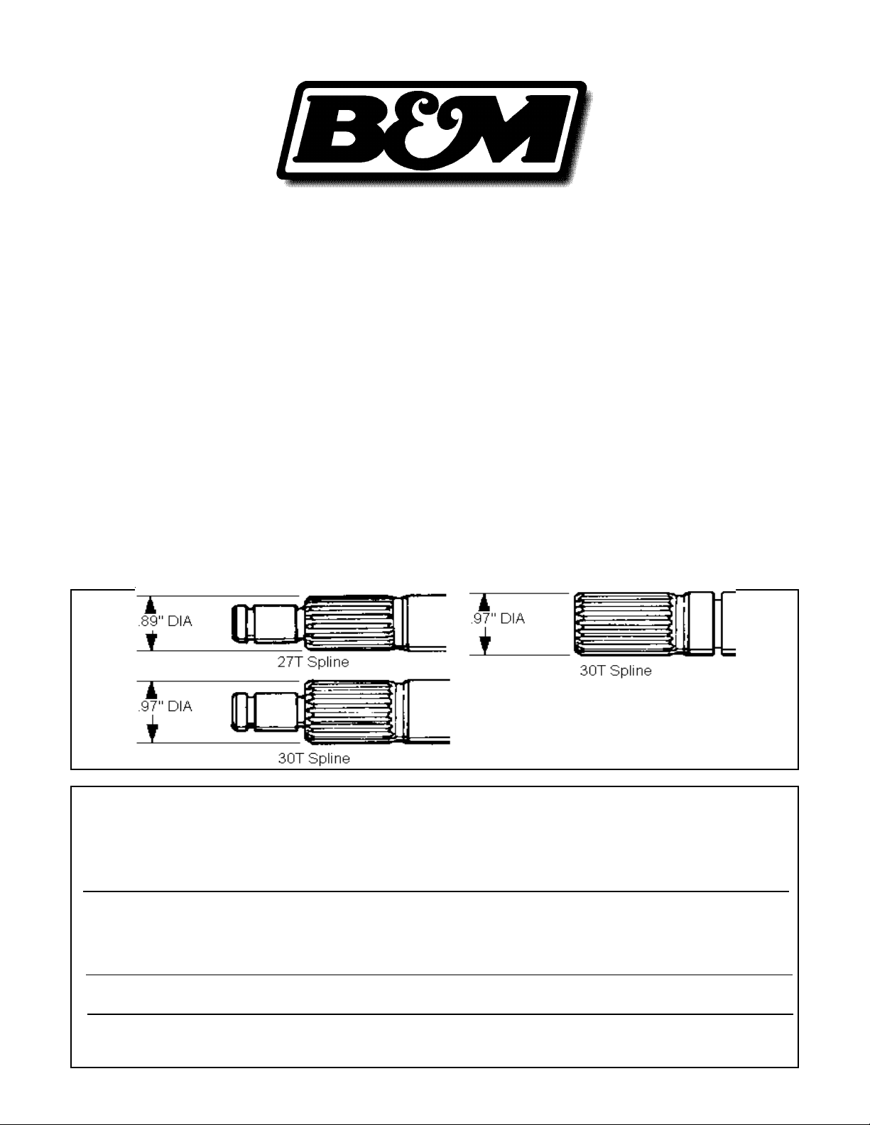
These GM lockup clutch style (TCC)
torque converters are made in versions
for several automatic transmissions,
three different input shaft spline tooth
numbers and a range of stall speeds.
The chart below shows the applications.
The new B&M torque converter can
be used as either a lockup or non lockup
unit. If the vehicle currently has an operational TCC it will continue to operate if no
other changes are made to the vehicle.
Optionally the TCC can be bypassed
(except on 4L60E transmissions) if desired as covered in STEP 22 below.
If the torque converter is being installed into a vehicle that was not originally equipped with a transmission with
lockup torque converter the TCC will not
operate and the converter will be a nonlockup converter. The TCC in a TH700R4, 4L60, TH200-4R or TH350C can be
made to operate in this type of applica-
Fig. 1
Transmission Input Shaft Type Part No.
TH200-C 27 Tooth HoleShot 2400 70415
TH200-4R 27 Tooth HoleShot 2400 70415
TH700-R4 1982-84 27 Tooth HoleShot 2400 70415
TH200-C 27 Tooth HoleShot 2000 70416
TH200-4R 27 Tooth HoleShot 2000 70416
TH700-R4 1982-84 27 Tooth HoleShot 2000 70416
TH700-R4 1984-93 (4L60) & 1993-96 4L60E 30 Tooth HoleShot 2000 70417
TH700-R4 1984-93 (4L60) & 1993-96 4L60E 30 Tooth HoleShot 2400 70419
TH700-R4 1984-93 (4L60) & 1993-96 4L60E 30 Tooth Tork Master 2000 70420
TH700-R4 1984-93 (4L60) & 1993-96 4L60E 30 Tooth Tork Master 2400 70418
TH700-R4 1984-93 (4L60) & 1993-96 4L60E 30 Tooth Traveler 70422
TH700-R4 1984-93 (4L60) & 1993-96 4L60E 30 Tooth HoleShot 3000 70425
TH200-C 27 Tooth HoleShot 3000 70426
TH200-4R 27 Tooth HoleShot 3000 70426
TH700-R4 1982-84 27 Tooth HoleShot 3000 70426
4L60E 1998-04 & 2000-04 4L65E 30 Tooth HoleShot 2000 70440
4L60E 1998-04 & 2000-04 4L65E 30 Tooth HoleShot 2400 70441
Torque Converter Applications
Printed in the U.S.A.
9500354-04
Page 2
tion by using the B&M Converter Lockup
Control (#70244 for mechanical drive
speedometers, #70248 for GM electronic speed sensor applications).
These torque converters can be
used on the GM 4L60E electronically
controlled transmission used on 1993 96 Chevrolet and GMC trucks and 199497 Camaros and Firebirds. On later
model vehicles equipped with an LS1
type engine, the input shaft is longer and
can only use the 70440 and 70441 converters. For this transmission (4L60E)
you must not make any electrical connection changes. Using it as a non
lockup unit will cause error codes to be
generated and the "Check Engine" light
will be illuminated.
TRANSMISSION REMOVAL
The TH200C, TH200-4R, TH700-R4 and
4L60E are METRIC dimensioned and
have METRIC fasteners.
Because of variations between different vehicle models we cannot cover each
in detail. Instead we will outline a basic
removal and installation procedure. The
sequence of the following procedures
may have to be changed to suit different
vehicle installations. We recommend
you change the transmission fluid and
filter when installing your B&M torque
converter.
Automatic transmissions normally
operate between 150 F and 250 F. It is
recommended that the transmission be
allowed to cool thoroughly to avoid burns
from hot oil and parts. The vehicle must
be off the ground for ease of transmission removal. A vehicle hoist is best,
however jack stands or wheel ramps will
work fine. MAKE SURE THE VEHICLE IS
FIRMLY AND SECURELY SUPPORTED!! A
transmission jack should be used to
prevent personal injury and or transmission damage during removal and installation. Have a small box handy to put nuts
and bolts in so they don’t get lost. A drain
pan to catch oil is also required.
STEP 1. Place drain pan under the
transmission to catch the oil. Drain the oil
pan by first removing the front bolts then
working from the front loosen all the
remaining pan bolts. If the pan sticks use
a screwdriver to pry the pan loose. Again
working from front to rear allow the pan to
tilt down in the front and drain as the
remaining bolts are removed. Once
drained replace the oil pan and hold in
place with one bolt at each corner. To
avoid all this mess next time you service
your transmission, you may want to consider installing a B&M Drain Plug Kit,
#80250 while the oil pan is off the transmission.
STEP 2. Remove the driveshaft (and
torque arm if equipped) being careful not
to drop the U-joint bearings. It’s a good
idea to tape the bearings in place and
wrap the smooth seal diameter of the
slip yoke to prevent damage. It may be
necessary to remove or disconnect any
exhaust pipes and/or hangers during
transmission removal. Remove transfer
case if equipped.
STEP 3. Disconnect the cooler lines.
Use a fitting wrench to avoid damaging
the tube compression nuts. Some models are equipped with a T.V. cable that
runs from the transmission up to the
throttle linkage on the engine. Disconnect the T.V. cable at the engine end and
feed the cable down so it hangs freely
from the transmission. Disconnect any
electrical connectors from the sides of
the case. Be sure to note or label the
position of each corresponding connector. Disconnect the transmission shifter
cable from the shift lever. Disconnect the
speedometer cable or electrical Vehicle
Speed Sensor connector at rear of transmission.
STEP 4. Remove the bell housing dust
cover to expose the torque converter.
Remove the three converter bolts. The
converter should now rotate freely. If it
does not pry the converter back slightly
and free it from the crankshaft.
STEP 5. Place transmission jack under
transmission and take the load off the
crossmember. If the vehicle is equipped
with a rear mounted distributor on the
engine, it is advisable at this point to
remove the distributor cap so it will not be
damaged as the transmission is lowered. Remove the crossmember assembly.
Dowel pin must
protrude 1/2" for
proper transmission engagement
Fig. 2
STEP 6. Remove the bellhousing
bolts, it may be necessary to lower the
transmission slightly to gain clear access to the bolts. Finish lowering the
transmission until engine is balanced
on it’s mounts then pull the transmission
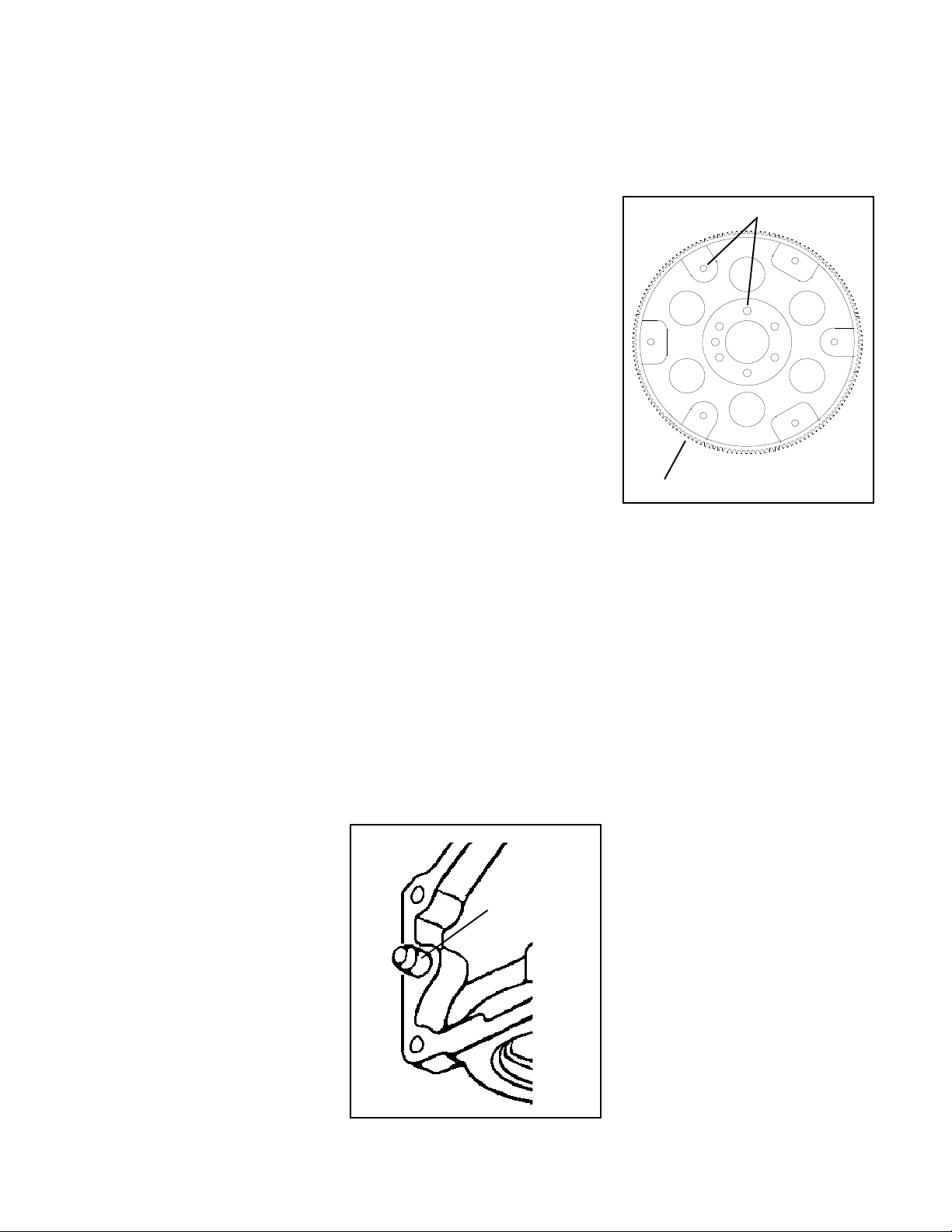
Inspect bolt holes
Inspect ring gear teeth
Fig. 3
slightly away from the engine. Make sure
the converter stays with the transmission and does not fall out. It may be
necessary to remove the dipstick tube at
this point to continue lowering the transmission. Remove transmission and
converter assembly from vehicle.
With the transmission completely out
of the vehicle the torque converter can
easily be removed by pulling it straight off
the front. Drain the torque converter as
completely as possible then cover the
hub to keep out dirt.
STEP 7. Inspect the engine block’s
transmission mounting face to be free of
any dirt or burrs. Make sure both dowel
pins are installed and stick out of the
block at least 1/2" to insure proper transmission alignment, see (Fig. 2).
STEP 8. Remove and inspect the
flexplate for distortion, cracks or damaged ring gear teeth, see (Fig. 3). If the
flexplate shows any damage it should be
replaced. Do not attempt to repair a damaged flexplate.
STEP 9. Assemble the flexplate to
crankshaft and align all holes before
installing the bolts. When properly installed the raised inner lip on the
flexplate should face away from the
crankshaft flange. Torque the bolts to 60
ft.lbs.
STEP 10. Carefully remove the front seal
from the oil pump housing. CAUTION:
The oil pump housing used in these
transmissions is made of an aluminum
2
Page 3

Pump seal removal and installation
Locate seal retainer tab
at 5 O'clock position
alloy and can be easily damaged during
seal removal. We recommend the following seal removal procedure to minimize the chance of damaging the pump
housing, see (Fig. 4).
1. Raise the transmission (or place on
bench) so that the seal is accessible
from the lower side of the transmission.
2. Using a common (flat) screwdriver
collapse the seals outer flange as
shown. Be careful not to damage the
housing with the screwdriver.
3. With the outer flange collapsed the
seal should pry out easily. Again take
care not to damage or gouge the housing. Once the seal is removed use a lint
free rag wrapped around a thin piece of
wood or other soft material, (to avoid
scratching the seal bore) to clean the
seal bore thoroughly.
STEP 11. Coat the outer diameter of the
new oil seal with “Locktite, 609” or
“Permatex, Secures Gears” cylindrical
retaining compound. Then using a small
block of wood between the seal and
hammer, carefully tap the seal evenly
into the housing until fully seated. If the
transmission was equipped with a seal
retainer, install the retainer onto the
housing as shown, see (Fig. 4).
STEP 12. Hold your B&M torque converter against the crankshaft and
flexplate to check the pilot hub fit. The
converter pilot hub should fit in the crankshaft snugly with no excessive slop. A
tight fit indicates burrs or debris in the
crankshaft pilot diameter. The burrs or
debris can be removed with sand paper.
STEP 13. Pour 1 quart of transmission
Fluid into the B&M torque converter so
there will be some lubrication on initial
startup. Lubricate the converter’s pump
drive hub with clean transmission fluid.
STEP 14. Install the B&M torque converter onto the transmission. Push the
converter in while rotating it to engage the
input shaft, reaction shaft and pump
Fig. 4
drive tangs. Place a straight edge across
the bellhousing face and measure the
distance to the torque converter’s drive
lug face. The drive lug must be at least 1"
inside the bellhousing, see (Fig. 5). A
measurement of less than 1" indicates
the torque converter is not fully engaged
in the transmission. Continue to push in
and rotate the converter until you obtain
full engagement. If you install the trans-
mission without full converter engagement, you will damage the oil pump.
STEP 15. Place the transmission in po-
sition on transmission jack. Make sure
the jack supports the transmission on a
wide area so the oil pan is not crushed.
Install the transmission / converter
against the engine. The transmission
should engage the dowel pins and sit flat
against the block with hand pressure
only. If the transmission does not sit flat
against the engine, the converter is not
fully engaged in the transmission or
some other interference problem exists.
Drive lug face must be at least 1"
inside front edge of bellhousing
Fig. 5
Do not attempt to pull the transmission
up to the engine with the bellhousing
bolts as this can cause transmission or
torque converter damage.
STEP 16. Once the transmission is in
position against the engine, install the
bellhousing bolts and torque to 35 lb.ft. At
this point the torque converter should
turn freely. A tight converter indicates
improper engagement, distorted
flexplate or binding pilot hub. This condi-
tion must be corrected before going
any further.
STEP 17. Inspect transmission mount.
Worn, cracked or broken transmission
and/or engine mounts should be replaced. Raise transmission and install
crossmember assembly then tighten all
bolts. Install three (M10 x 1.5) flexplate to
converter bolts. Install the first bolt finger
tight then use the starter motor to “bump”
each drive lug into position. When all
three bolts are installed torque them to
47 Nm (35 lb.ft.).
STEP 18. Remove the oil pan and filter.
The filter suction tube O-ring may stick in
the pump body, if it does make sure to get
it out. Assemble two (2) O-rings on a new
oil filter. Some filters have a
preassembled seal on the suction tube,
if the filter you are using has a
preassembled seal do not use the Orings. Lubricate the suction tube seal
with clean transmission fluid and install
filter into the transmission.
STEP 19. Remove all old gasket material from the pan and case flange. Install
a new pan gasket then assemble pan to
the transmission. Install ALL of the pan
bolts (install shifter cable bracket if
equipped) finger tight first then torque to
8 lb.ft. DO NOT use a sealant on the pan
gasket and don’t over torque the pan
bolts, this will damage the gasket and
cuase the pan to leak transmission fluid.
STEP 20. If your transmission is
3
Page 4

equipped with a TV cable, reconnect and
adjust the TV cable, see (Fig. 6). IMPOR-
TANT: You must reset the TV cable before
operating the transmission. Failure to
reset the TV cable may result in poor shift
quality and early transmission failure.
STEP 21. Reconnect speedometer
cable or VSS connector, any electrical
connectors and shifter cable. Make sure
the cooler tube connector fittings are tight
in transmission case, then either connect cooler lines and tighten tube compression nuts with a fitting wrench (to
avoid damaging the nuts) or reinstall the
retaining clips.
STEP 22. If the vehicle originally had a
TCC and transmission installed, plug in
the electrical connector on the left side of
the case (See Fig. 7) and the TCC in the
new converter will operate. If you do not
want the TCC to operate, cut the wire
going to pin marked “A” on the TCC plug
going into the electrical connector on the
left side of the case. Tape the ends of the
wire to prevent shorts.
If the transmission is installed in a
vehicle that did not originally have a TCC
and transmission the TCC will not operate. The lockup clutch can be made to
operate in this type of application by
using the B&M Converter Lockup Control
(#70244 for mechanical drive speedometers, #70248 for GM electronic speed
sensor applications). This unit connects
to the speedometer drive cable or to the
plug for the electronic speed sensor and
lets the driver set the speed at which the
TCC will lock and unlock to any speed
between 30 and 90 mph.
STEP 23. Install driveshaft (and torque
arm if used). Make sure the U-joint bearings are properly positioned in their
seats. Tighten U-joint nuts or bolts securely.
STEP 24. Lower vehicle but keep the
rear wheels off the ground if possible.
Add five quarts of transmission fluid to
the transmission. Place transmission in
NEUTRAL and start the engine. Add fluid
to transmission (as per the manufacturers' rfluid check recommendation) until
the fluid level is between the FULL and
ADD marks. Shift the transmission
through all gear positions. If the wheels
are off the ground, allow the transmission to shift through all gears several
times. Place selector in NEUTRAL and
check the fluid level again. DO NOT
OVERFILL. Check for leaks around the oil
pan, cooler lines, etc. Turn off engine
then lower vehicle and test drive.
OTHER B&M PRODUCTS
TV Cable adjustment proceedure
Fig. 6
B&M Manufactures several other
transmission products ideally suited for
4L60E, TH700-R4 and TH200-4R transmissions.
1. TH700-R4 (#70235) & 4L60E
(#70265) TRANSPAK The Transpak kits
are designed to increase the torque capacity and significantly improve the shift
feel in addition to promoting longer
transmission life. All of the necessary
parts and instructions, including gaskets and a new oil filter are supplied with
the kit.
2. TH200-4R TRANSPAK (#35229) The
TH200-4R Transpak is designed to increase the torque capacity and significantly improve the shift feel in addition to
promoting longer transmission life. All of
the necessary parts and instructions,
including gaskets and a new oil filter are
supplied with the kit.
3. POWER SWITCH KIT (#80217) The
B&M Power Switch Kit allows the lock-up
portion of the converter to be temporarily
eliminated and the converter reverted to
a standard type converter. This gives the
ability to operate the vehicle with a standard type torque converter when it is
more desirable than the lock-up type.
TH700-R4 (4L60) Shown
4. TH700-R4 Special Deep Pan (#70289)
adds approximately 3 quarts extra oil
capacity. This attractive chrome pan also
incorporates a built in drain plug to help
simplify the more frequent oil changes
required of high performance transmissions. The larger surface area and fluid
volume of this pan helps reduce the
transmissions oil temperature thereby
promoting longer transmission life.
5. TRANSMISSION OIL COOLERS. Design features of the new “High Tech”
transmissions cause them to run hotter
than earlier transmissions. We recommend that every vehicle using an automatic transmission in heavy duty applications (racing, towing, RV, commercial,
off road, fleet) have an auxiliary transmission oil cooler. Addition of an auxiliary oil
cooler will not only reduce transmission
oil temperature but it will also significantly reduce the heat load on the radiator. Heat is a major cause of automatic
transmission failure, an auxiliary oil
cooler is an inexpensive guard against
overheating and failure. B&M offers a
complete range of transmission coolers
to suit every application, available at your
B&M dealer. A non-lockup torque con-
Connector for TCC Plug
TCC Plug
Fig 7
4
Page 5

verter installation will run warmer than
a lockup installation, and particularly
needs a transmission cooler.
6. TEMPERATURE GAGE (#80212) Most
transmission and converter failures are
traced directly to excessive heat. The
B&M transmission temperature gage
can save you a costly repair bill by warning you ahead of time of an overheating
transmission. The B&M temperature
gage is extremely accurate and dependable, it comes with all necessary hardware and is easy to install.
7. TH700-R4 KICKDOWN KIT (70237)
The TH-700 has a hydraulic circuit that
causes a forced 4-3 down shift whenever
the throttle is opened past two thirds
travel. In some applications a forced 4-3
down shift is undesirable. After many
customer requests B&M has developed
an easily installed kit that will eliminate
the part throttle 4-3 down shift feature.
This kit does not alter normal shift
speeds or affect detent operation. This
kit is best installed along with B&M’s
70235 Transpak. It can also be installed
independent of other modifications, and
valve body removal is not required.
8. 4L60E SHIFTPLUS (#70380) For those
of you who have a 1993-1998 electronically controlled 4L60E, the SHIFTPLUS
is a great addition to firming up those soft
feeling factory shifts. With in a few minutes for installation, you can quickly and
simply increase your transmission line
pressure with just a flip of a switch. There
is no need to remove the transmission
pan to install the SHIFTPLUS. You transmission will benefit from reduced wear
and slippage, which causes excessive
heat and can lead transmission life failure. You only need simple tools to install
and can easily go back to stock by simply
flipping a switch.
Trans cooler lines
w/retaining clips
2 Piece Bellhousing
Electrical Connector
4L65E shown
Fig. 8
5
 Loading...