

Page 1
DZ33I, English
OWNER’S OPERATING
& INSTALLATION
MANUAL
CTX GEMINI SERIES OVENS
DZ33I
CTX ® 1400 Toast Master Drive Elgin, IL. 60120 847-741-3300
A Middleby Company www.middleby.com
Part No. 69982
7/1/13
Page 2

Model No._________________Serial No.__________________________Installation Date________
CTX®
NO QUIBBLE LIMITED WARRANTY
(U.S.A ONLY)
MIDDLEBY MARSHALL HEREINAFTER REFERRED TO AS THE SELLER, WARRANTS
EQUIPMENT MANUFACTURED BY IT TO BE FREE FROM DEFECTS IN MATERIAL AND
WORKMANSHIP FOR WHICH IT IS RESPONSIBLE. THE SELLER’S OBLIGATRION UNDER THIS
WARRANTY SHALL BE LIIIMITED TO REPLACING OR REPAIRING AT SELLER’S OPTION,
WITHOUT CHARGE, ANY PART FOUND TO BE DEFECTIVE AND ANY LABOR AND MATERIAL
EXPENSE INCURRED BY SELLER IN REPAIRING OR REPLACING SUCH PART, SUCH
WARRANTY SHALL BE LIMITED TO THE ORIGINAL PURCHASER ONLY AND SHALL BE
EFFECTIVE FOR A PERIOD OF ONE YEAR FROM DATE OF ORIGINAL INSTALLATION, OR 18
MONTHS FROM DATE OF SHIPMENT, WHICHEVER IS EARLIER; PROVIDED THAT TERMS OF
PAYMENT HAVE BEEN FULLY MET.
This warranty is valid only if the equipment is installed, started and demonstrated under the
supervision of a factory certified installer.
Normal maintenance functions, including lubrication, cleaning or customer abuse are not covered by
this no quibble warranty.
Seller shall be responsible only for repairs or replacements of defective parts performed by Seller’s
authorized service personnel. Authorized service agencies are located in principal cities throughout
the contiguous United States, Alaska and Hawaii. This warranty is valid in the 50 United States and is
void elsewhere unless the product is purchased through Middleby International with warranty
included.
The foregoing warranty is exclusive and in lieu of all other warranties, expressed or implied.
There are no implied warranties of merchantability or of fitness of a particular purpose.
The foregoing warranty shall be Seller’s sole and exclusive obligation and Buyer’s sole and exclusive
remedy for any action including breach of contract or negligence. In no event shall Seller be liable for
a sum in excess of the purchase price of the item. Seller shall not be liable for any prospective or lost
profits of Buyer.
CTX® 1400 Toastmaster Drive Elgin, IL 60120 USA (847) 741-3300
Page 3

©2013 CTX www.middleby.com/midmarsh/
FOR YOUR SAFETY
DO NOT STORE OR USE GASOLINE OR OTHER
FLAMMABLE VAPORS AND LIQUIDS IN THE
VICINTIY OF THIS OR ANY OTHER APPLIANCE
WARNING
Improper installation, adjustment, alteration,
service or maintenance can cause property damage,
injury or death. Read the installation, operating and
maintenance instructions thoroughly before installing
or servicing this equipment.
NOTICE:
This Operating and Installation Manual should be given to the user. The operator of the oven
should be familiar with the functions and operation of the oven.
This manual must be kept in a prominent, easily reachable location near the oven.
It is suggested to obtain a service contract with a manufactures certified service agent.
NOTICE
CONTACT YOUR LOCAL SERVICE COMPANY TO PERFORM MAINTENANCE AND REPAIRS.
A SERVICE AGENT DIRECTORY IS SUPPLIED IN YOUR
INSTALLATION KIT.
NOTICE
Using any parts other than genuine
CTX factory
manufactured parts relieves the manufacturer
of all warranty and liability.
NOTICE
CTX (Manufacturer) reserves the right to
change specifications at any time.
The equipment warranty is not valid unless the oven is installed, started and demonstrated under the
supervision of a factory certified installer.
WARNING
Page 4

TABLE OF CONTENTS
SECTION 1- DESCRIPTION ........................................................................ 5
A. Component Location………………………………………………..........6
B. Component Function……………………………………………………...7
C. Oven Specifications…………………………………………………….8-9
D. Dimension Drawings………………………………………………….9-12
SECTION 2- INSTALLATION………………………………………………….13
A. Inspect For Shipping Damage………………………………………….13
B. Placement of Oven………………………………………………………13
C. Items for Stacking Oven………………………………………………...13
D. Base Section Assembly……………………………………………..14-15
E. Mounting Single Oven Onto Base Assembly……………………..15-16
F. Stacking and Mounting Two Ovens………………………………..16-17
G. Stacking and Mounting Three Ovens……………………………........17
H. Stacking and Mounting Four Ovens……………………………………
I. Electrical Connection……………………………………………………17
J. “Loose” Parts……………………………………………………………..17
SECTION 3- OPERATION……………………………………………………..18
A. Location of Controls……………………………………………………..18
B. MenuSelect™ Control Operation and Programming…………….19-30
C. Cooking in a CTX Oven……………………………………………..31-32
D. Time and Temperature Guide.……………………………………..32-36
SECTION 4- CLEANINING.........................................................................37
A. Cleaning the Cooling Fan Filter………………………………………...37
B. Oven Cleaning Operation…………………………………...………37-38
C. Cleaning “Loose” Parts………………………………………………….38
D. Cleaning the Exterior………………………………………………...….39
SECTION 5- MAINTENANCE & TROUBLESHOOTING…………….….....39
A. Chart 1- Error Messages…………...…………………………………...39
B. Chart 2- Troubleshooting………………………………………………..40
SECTION 6- PARTS LISTS………………………………………………..41-42
Oven Open Rear View………………………………………………………43
Oven Elements Exposed View……………………………………………..44
Oven Front Closed View…………………………………………………….45
Oven Front Open View………………………………………………………46
Single Belt Conveyor………………………………………………………...47
Split Belt Conveyor…………………………………………………………..48
SECTION 7- ELECTRICAL SCHEMATICS……………………………...…..49
A. Model DZ33I, 208/230V, 3Ph Schematic……………………………..49
B. Model DZ33I, 380/415V, 3Ph Schematic…………...………………...50
C. Model DZ33I, 230V, CE, 3Ph Schematic……………………………..51
Page 5
D. Model DZ33I, 380V, CE, 3Ph Schematic……………………………..52
This manual must be kept for future reference
Note:
Wiring diagrams are contained in the manual and
are also located in the oven.
SECTION 1 - DESCRIPTION
CTX Series oven is:
• Electrically powered • Conveyorized
• Zone heated by infrared panels • Electronically controlled
CTX Oven Model:
• DZ33I – 31” (787 mm) long cooking chamber with a MenuSelect™ control.
NOTE: “DZ” designation on ovens stands for: “D” = Dual Conveyor, “Z” = Zone Temperature
Control.
DZ33I
Figure 1
Page 6
A. Component Location
Locking Casters
Oven Base
with Legs
Fan
Warning
Light
Conveyor
Motor
Conveyor
Cooking Chamber
Conveyor Belt or Belts
Crumb Tray
Draft Curtain
Control Circuit
Breakers
Cooling
Fan
Control with
Digital Display
Oven Data Plate
Page 7
Figure 1-2
B. Component Function
1. Oven Controller
The controller controls all functions of the oven. The cooking temperatures can be set from 200F
to 900F (93C to 509C). Cooking times (conveyor speed) can be set from 1:00 minute to 60:00
minutes on the DZ33I.
Controller features a self-cleaning mode, a programmable automatic ON/OFF timing mode, and
an energy conserving standby mode. Also included is a service mode designed to assist the
service technician.
The Menu Select control contains 10 menu keys which can be preset to control both oven
temperature and cook time. The operator must then press only the menu key for the desired
product being cooked.
2. Infrared Heating Panels
Heating panels are positioned above and below the conveyor belt in the oven chamber
(figure 1-3). When energized these panels emit infrared long waves. These waves do not heat the
air through which they pass. Instead the waves are absorbed by the outer surface of the product
transported through the oven on the conveyor belt. Using this application, food is placed on the
conveyor and the unique properties of the infrared waves cause it to cook from the outside to the
center in traditional fashion.
Figure 1-3
DZ33I Heat Zones
Page 8

3. Conveyor
Model
No
AC
Volts
Phase
Hz
Connected
kW
AVG
Operating
kW
Connected Load (Amps)
Required
Breaker
(Amps)
L1
L2
L3
N
DZ33I
208
1
50/60
8.95
3.1
45.7
45.7
--
--
60
DZ33I
208
3
50/60
9.5
3.1
30.3
30.3
19.8
--
40
DZ33I
240
1
50/60
10.0
3.1
41.7
41.7
--
--
60
The conveyor is used to convey the product through the oven deck (chamber). The conveyor is
made up of 1to 2 stainless steel wire belts which can travel in either direction around the frame.
The conveyor is controlled by the controller and can travel at speeds from 1:00 to 60:00 minutes.
The speed of the conveyor determines how long the product will be in the cooking chamber which
is the cooking time.
CAUTION: All DZ ovens are Voltage Specific. Check the oven data plate for the voltage. Applying the wrong voltage can
immediately damage the oven. Refer to the Installation Section of this manual for complete instructions before installing
an oven.
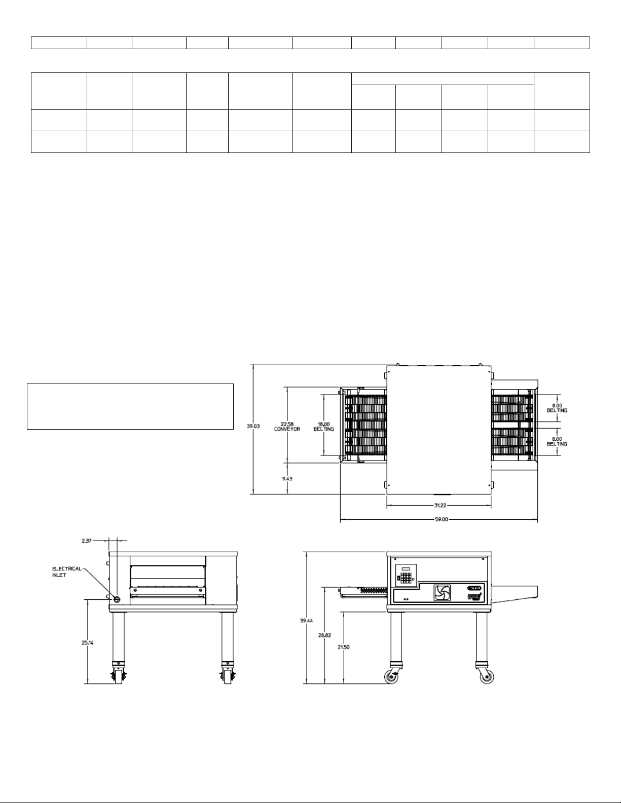
C. Oven Specifications
Figure 1-1 Dimensions DZ33I
Single Oven on Base and Casters
Overall Height 39.44” (1001.8mm)
Overall Depth 39.03” (991.4mm)
Overall Length 59.00” (1499mm)
Double Oven on Base and Casters
Overall Height 55.32” (1328.9mm)
Overall Depth 39.03” (991.4mm)
Overall Length 59.00” (1499mm)
Triple Oven on Base and Casters
Overall Height 65.17” (1655.3mm)
Overall Depth 39.03” (991.4mm)
Overall Length 59.00” (1499mm)
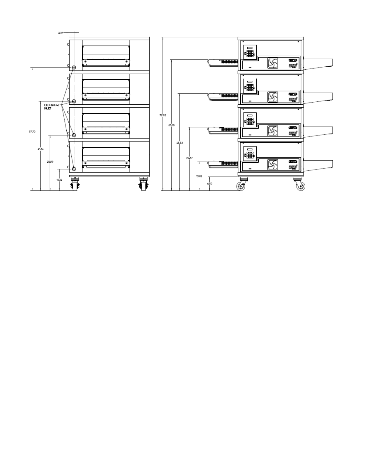
Quad Oven on Base and Casters
Overall Height 72.02” (1829.3mm)
Overall Depth 39.03” (991.4mm)
Overall Height 59.00” (1499mm)
Oven Chamber Dimensions
Overall Height 5.5” (140mm)
Overall Width 22.25” (565mm)
Overall Length (Heating Zone) 31.22” (793mm)
Conveyor Baking Area 3.88sq. ft. (0.36sq. m.)
Stainless Steel Single Conveyor Belt Width 18” (457mm)
Stainless Steel Duel Conveyor Belt Width (2) 8.00” (203mm)
Net Weight of Single Unit 362 lbs. (164.2 kg)
Temperature Range 1500F-9000F (66.50C-4820C)
Oven Electrical Specification Chart
NOTE: A separate ground wire must be supplied with each oven; conduit may not be used as a ground.
NOTE: Supply wire must be rated minimum 900C (1940F).
Domestic Amp Loading Charts
DZ33I Domestic
Page 9
DZ33I
240
3
50/60
10.0
3.1
27.6
27.6
18.1
--
40
Model
No
AC
Volts
Phase
Hz
Connected
kW
AVG
Operating
kW
Connected Load (Amps)
Required
Breaker
(Amps)
L1
L2
L3
N
DZ33I
(CE Listed)
230
3
50/60
9.2
3.1
18.9
18.9
32.6 - 40
DZ33I
(CE Listed)
380
3
50/60
8.4
3.1
18.9
9.2
9.2
8.9
30
We reserve the right to change specifications and product
design without notice. Such revisions do not entitle the
buyer to corresponding changes. Improvements, additions
or replacements for previously purchased equipment.
D. Dimension Drawings
1. Dimension drawing of Single DZ33I Oven on Base.
DZ33I International
Note: All figures in parentheses are in millimeters.
Page 10
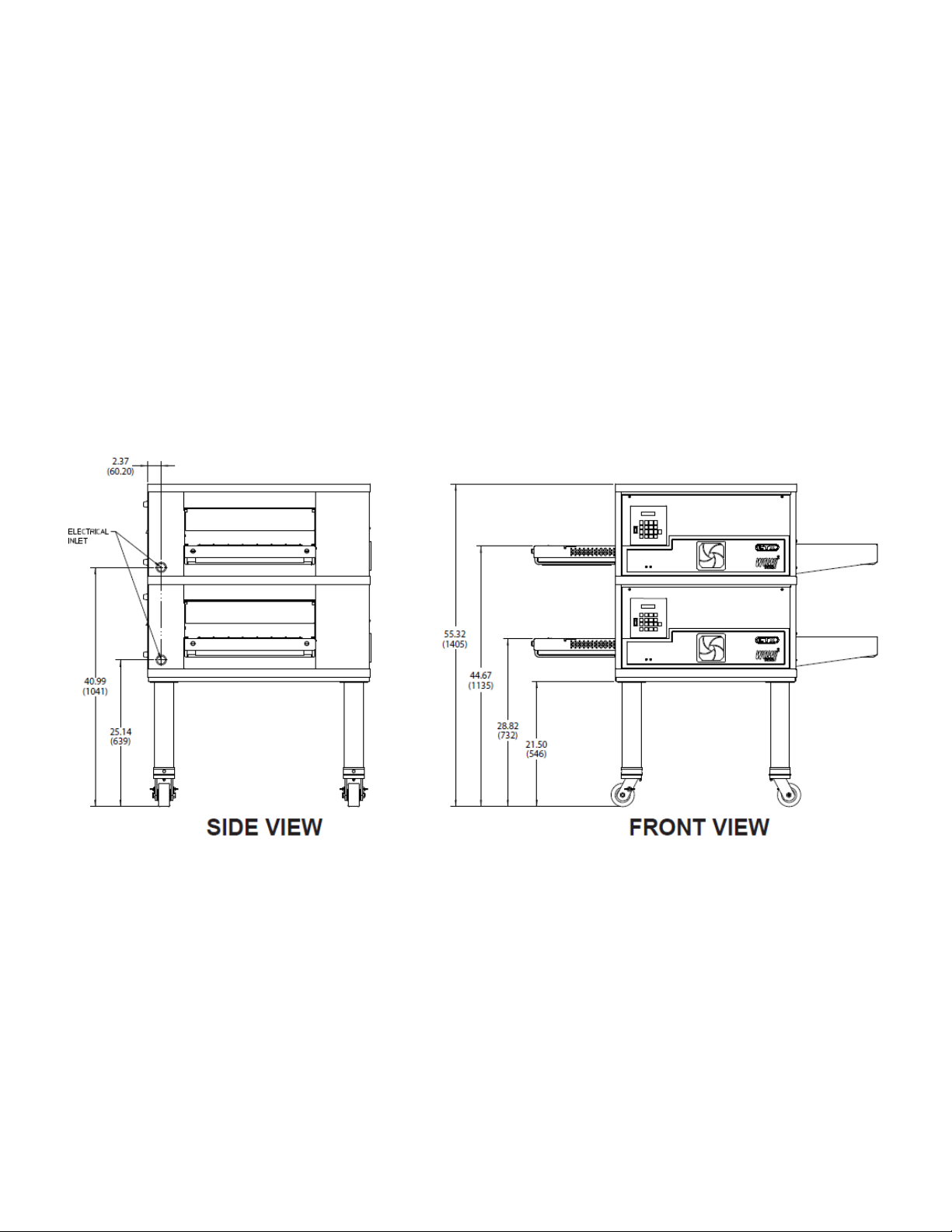
2. Dimension drawing of two stacked DZ33I ovens on base.
Note: All figures in parentheses are in millimeters.
3. Dimension drawing of three stacked DZ33I ovens on base.
Note: All figures in parentheses are in millimeters.
Page 11

4. Dimension drawing of a Quad stacked DZ33I ovens on base.
Note: All figures in parentheses are in millimeters.
Page 12
Side View Front View
A. Inspect for shipping Damage
All shipping container should be examined for
damage before and during unloading. This
equipment was carefully inspected and
SECTION 2 – INSTALLATION
packaged at the factory. The freight carrier has
assumed responsibility for its safe transit and
delivery. If equipment is received in damaged
condition, either apparent or concealed, a
Page 13

claim must be made with the delivering
Quantity
Description
2
4”x4”x4’ (10.2cm x 10.2cm x 61cm)
board
2
4”x4”x2’ (10.2cm x 10.2cm x 122cm)
board (stacking ovens only)
2
1-1/2”x7’ (3.8cm x 213cm) rigid pipe
Schedule 40
2
Custom M5 Lift (Vermette)
carrier.
1. Apparent Damage or Loss- If damage or
loss is apparent it must be noted on the
freight bill or express receipt at the time
of delivery, and it must be signed by the
carrier’s agent (driver). If this is not
done, the carrier may refuse the claim.
The carrier will supply the necessary
claim forms.
2. Concealed Damage or Loss- If damage
or loss is not apparent until after
equipment is uncrated, a request for
inspection of concealed damage must
be made with carrier within 10 days. The
carrier will make an inspection and will
supply necessary claim forms. Be
certain to retain all contents plus
external and internal packaging/crating
materials for inspection.
B. Placement of Oven
Some very important considerations must be
made when choosing the place where the oven
is to operate.
3. This Oven is conveyorized and operates
continuously. It should be placed so it
fits into the “flow” of the operation.
4. Drafts entering the oven chambers can
cause inconsistent cooking results.
Check the area surrounding the oven
and eliminate sources of drafts such as
open windows or doors and fans or
other appliances that cause air
circulation.
5. Oven should be positioned so hot air
from and other piece of equipment
cannot enter oven cooling fan air intake
on oven front. Serious problems could
occur.
NOTE: To validate a new oven(s) warranty a certified
CTX installer must supervise Steps C through H of
installation.
C. Items for Stacking Oven
The following items are required for stacking
ovens:
Page 14
Item
Qty,
Part Number
Description
1
1
67880
INSUL, BASE PART A
2
2
67881
INSUL, BASE PART C
3
2
67882
INSUL, BASE PART B
PARTS LISTED ABOVE ARE FROM 69978 KIT, DZ33I INSULATION
4
1
67884
WLDMT. BASE DZ33
5
1
67614
PANEL, TOP
6
4
66948
ASSY. LEG, CASTER
7
4
59156
SCR, SL TRUSS HD SS 10-32X1-1/2”
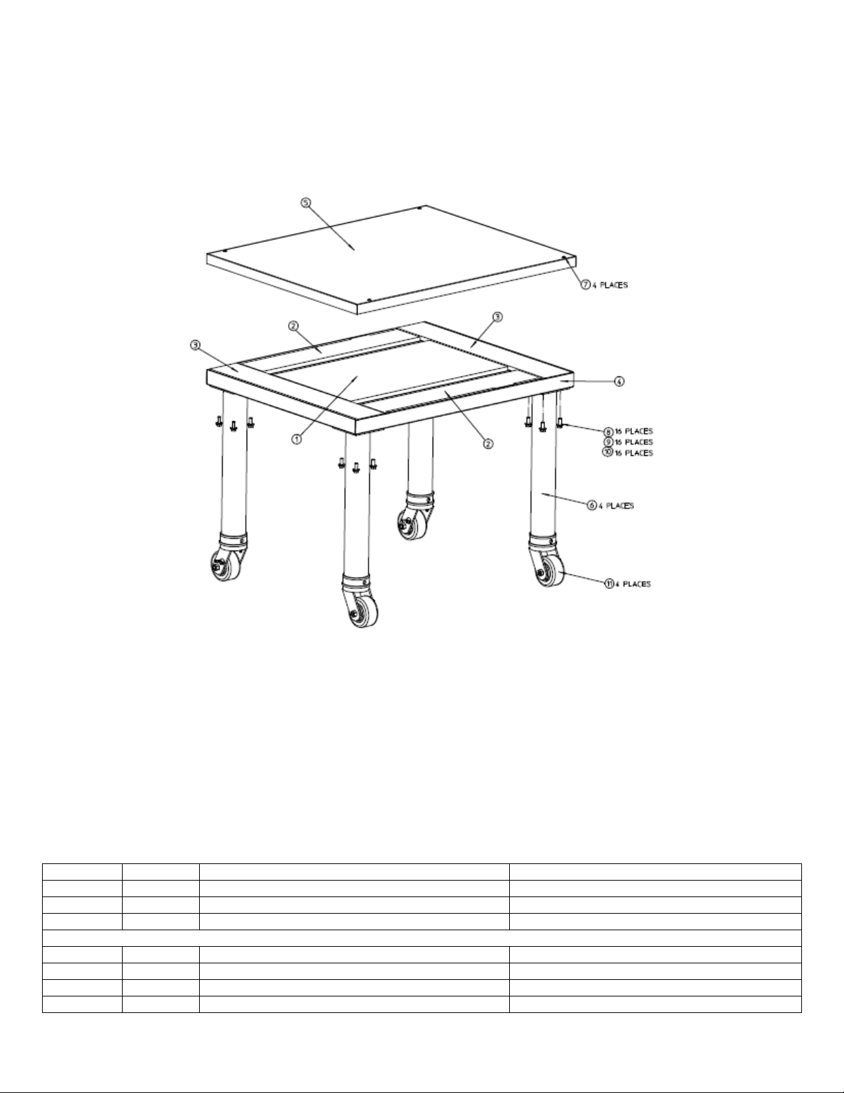
D. Base Section Assembly
1. Locate the carton containing the oven base. Remove and inventory the contents. Refer to the correct
parts lists below and also to Figure 2-1.
Figure 2-1
Single Oven Stand Parts
Page 15
8
16
21422-0001
WASHER, LOCK SPLIT 3/8” ZP
9
16
21416-0001
WASHER, FLAT SS 3/8”
10
16
2000531
SCR, CAP HX HD 3/8”-16X1” NP
Qty,
Part Number
Description
1
1
67880
INSUL, BASE PART A
2
2
67881
INSUL, BASE PART C
3
2
67882
INSUL, BASE PART B
PARTS LISTED ABOVE ARE FROM 69978 KIT, DZ33I INSULATION
4
1
67884
WLDMT. BASE DZ33
5
1
67614
PANEL, TOP
6
4
66948
ASSY. LEG, CASTER
7
4
59156
SCR, SL TRUSS HD SS 10-32X1-1/2”
8
16
21422-0001
WASHER, LOCK SPLIT 3/8” ZP
9
16
21416-0001
WASHER, FLAT SS 3/8”
10
16
2000531
SCR, CAP HX HD 3/8”-16X1” NP
Item
Qty,
Part Number
Description
1
1
67880
INSUL, BASE PART A
2
2
67881
INSUL, BASE PART C
3
2
67882
INSUL, BASE PART B
PARTS LISTED ABOVE ARE FROM 69978 KIT, DZ33I INSULATION
4
1
67884
WLDMT. BASE DZ33
5
1
67614
PANEL, TOP
6
4
66947
ASSY. LEG, CASTER
7
4
59156
SCR, SL TRUSS HD SS 10-32X1-1/2”
8
16
21422-0001
WASHER, LOCK SPLIT 3/8” ZP
9
16
21416-0001
WASHER, FLAT SS 3/8”
10
16
2000531
SCR, CAP HX HD 3/8”-16X1” NP
Item
Qty,
Part Number
Description
1
1
67880
INSUL, BASE PART A
2
2
67881
INSUL, BASE PART C
3
2
67882
INSUL, BASE PART B
PARTS LISTED ABOVE ARE FROM 69978 KIT, DZ33I INSULATION
4
1
67884
WLDMT. BASE DZ33
5
1
67614
PANEL, TOP
11
4
58930
CASTER
Double Oven Stand Parts
Triple Oven Stand Parts
Quad Oven Stand Parts
2. Lay Wldmt. Base (Item 4, Figure 2-1)
upside down on the floor and remove
the protective film from base. Attach the
four Assy. Leg, Caster (Item 5) using 16
SCR, Cap HX HD 3/8”-16X1” NP (Item
10), 16 Washer, Flat SS 3/8” (Item 9),
and 16 Washer, Lock Split 3/8” ZP (Item
8). For Quad screw casters directly into
basepad.
3. Turn the base assembly upright and set
aside. Also set aside 4 SCR, SL Truss
HD SS 10-32X1-1/2” (Item 7), and
E. Mounting Single Oven onto Base Assembly
Panel, Top (Item 5). The base will be used
to stack oven on, and the top secures to the
top of the oven top oven.
1. Cut the bands holding the protective
shipping carton to the skid. Carefully
remove the bands and lift the carton up
off the oven.
2. Cut the bands holding the oven to the
skid.
Page 16
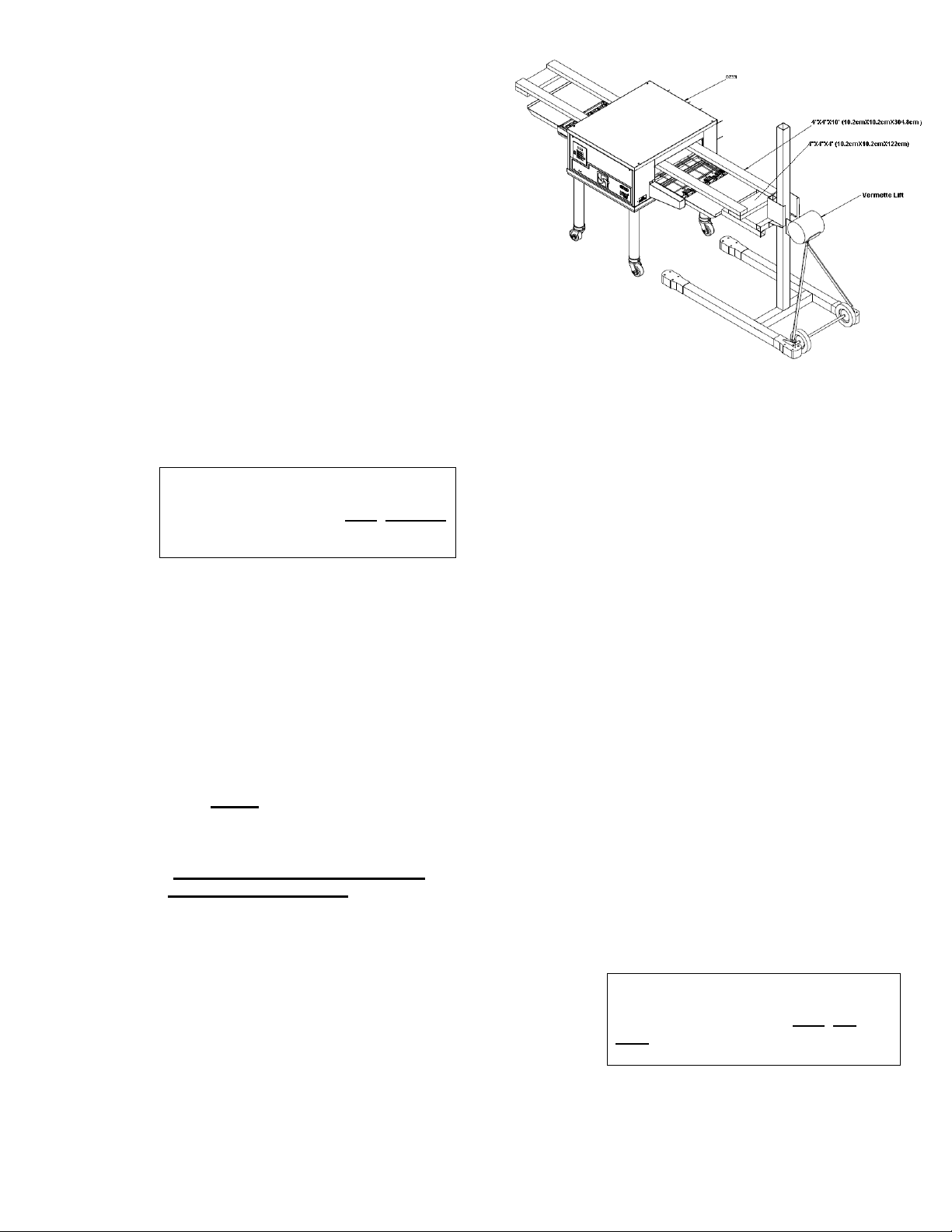
IMPORTANT: Lift the oven with the
4”X4”X10’ (10.2cmX10.2cmX122cm)
running through the oven only. DO NOT
lift the oven by the conveyor. Damage
WILL result.
IMPORTANT: Lift the oven with the
4”X4”X10’ (10.2cmX10.2cmX122cm)
running through the oven only. DO
NOT lift the oven by the conveyor.
Damage WILL result.
3. Slide the two 4”X4”X10’ (10.2cm X
10.2cm X 304.8cm) pieces of wood
through the oven cavity. The wood
pieces should be sticking out of the
oven equally on both sides. One of the
pieces of wood should be placed to the
rear of the oven and the other in the
front of the oven. See figure 2-2.
4. Position the two Vermette lifts on either
ends of the oven under the 10’
(304.8cm) pieces of wood, making sure
the legs with wheels are up as close as
possible to the skid. Place the two
4”X4”X4’ (10.2cm X 10.2cm X 122cm)
pieces of wood across the two Vermette
forks, at least 6” (182.88cm) in from the
end of the forks, and centered with the
10’ (304.8cm) pieces of wood running
through the oven cavity. See figure 2-2.
5. With the 4’ (122cm) pieces positioned
under the 10’ (304.8cm) begin to lift the
oven with the two Vermette lifts.
(keeping the oven level at all times).
6. When the oven is completely free from
the skid, slide it out from under the
oven. (dispose of the skid in accordance
with local regulations).
7. Lift the oven high enough to position the
stand under. Roll the stand under the
oven (do not roll the oven and lifts over
the stand) and lower onto the stand.
The bottom of the oven will wrap around
the stand.
(careful not to get hands or fingers
between oven and stand).
Figure 2-2
F. Stacking and Mounting Two Ovens
1. Cut the bands holding the protective
shipping carton to the skid. Carefully
remove the bands and lift the carton up
off the oven.
2. Cut the bands holding the oven to the
skid.
3. Slide the two 4”X4”X10’ (10.2cm X
10.2cm X 304.8cm) pieces of wood
through the oven cavity. The wood
pieces should be sticking out of the
oven equally on both sides. One of the
pieces of wood should be placed to the
rear of the oven and the other in the
front of the oven. See figure 2-2.
4. Position the two Vermette lifts on either
ends of the oven under the 10’
(304.8cm) pieces of wood, making sure
the legs with wheels are up as close as
possible to the skid. Place the two
4”X4”X4’ (10.2cm X 10.2cm X 122cm)
pieces of wood across the two Vermette
lift forks, at least 6” (182.88cm) in from
the end of the forks, and centered with
the 10’ (304.8cm) pieces of wood
running through the oven cavity.
(figure 2-2)
Page 17

5. With the 4’ (122cm) pieces positioned
IMPORTANT: Lift the oven with the
4”X4”X10’ (10.2cmX10.2cmX122cm)
running through the oven cavity only.
DO NOT lift the oven by the conveyor.
Damage WILL result.
IMPORTANT: Lift the oven with the
4”X4”X10’ (10.2cmX10.2cmX122cm)
running through the oven cavity only.
DO NOT lift the oven by the conveyor.
Damage WILL result.
under the 10’ (304.8cm) begin to lift the
oven with the two Vermette lifts (keeping
the oven level at all times).
6. When the oven is completely free from
the skid, slide it out from under the
oven. (dispose of the skid in accordance
with local regulations).
7. Elevate the upper oven high enough to
position the lower oven underneath.
8. Roll the stand with the lower oven under
the upper oven (do not roll the oven
and lifts over the lower oven) and lower
onto the lower oven. The bottom of the
oven will wrap around the top of the
lower oven.
(careful not to get hands or fingers
between ovens).
G. Stacking and Mounting Three Ovens
1. Follow the previous procedures in step
F.
(careful not to get hands or fingers
between ovens).
H. Stacking and Mounting Four Ovens
1. Follow the previous procedures in step
F.
(careful not to get hands or fingers
between ovens).
I. Electrical Connection
All wiring and electrical connections required
for the oven(s) must be performed by a
certified electrician. Each oven must be wired
according to the electrical specification for the
oven rating. See charts in Section 1, electrical
schematic in Section 7 and schematics
furnished with the oven. A separate ground wire
must be supplied with each oven. Conduit may
not be used as ground. Consult national or local
electrical codes for wire gauge and circuit
breaker ratings.
CAUTION: All DZ Series Ovens are manufactured
for voltage specific operation.
IMPORTANT: ALWAYS carefully check the data
plate voltage rating to be sure which voltage to apply
when installing a DZ Series oven. Applying the
wrong voltage can immediately damage oven.
If local codes allow, we recommend that flexible
conduit be used for final connection as the oven
assembly is on casters and the use of flexible
conduit will allow movement for cleaning.
I. Loose Parts
The aluminum crumb trays (PN 67932) (2 per
oven) are shipped mounted in place. They are
removable for cleaning and are considered
loose parts. They should be checked prior to
startup to be sure they are properly in place.
The stainless steel draft curtain and exit
shelves are packed in a separate carton inside
oven.
NOTE: Make sure protective plastic film is removed
from draft curtains before installation.
1. Draft Curtains, stainless steel (PN
322904) (2 per oven). These mount above
the conveyor at the ends of the cooking
chamber. They serve to reduce drafts
through the oven chamber and to reduce
heat loss to the environment. To install,
locate the thin rod above each entrance/exit
of the oven. Hang one draft curtain over
each rod. They are in their lowest position
when hanging vertical. To raise the curtains
to their highest position, swing them outward
until they are horizontal and then push in
toward oven chamber.
NOTE: Make sure protective plastic film is
removed from exit shelves before installation.
2. Exit Shelves, stainless steel (PN
69776) (2 per oven). These shelves
mount in cantilever fashion at the exit
and entrance end of the conveyor and
provide a landing zone for cooked
product. Depending on the operation
they may or may not be needed or used.
To install, place the slotted end of the
shelf over the crossbar at the end of the
conveyor extension frame.
Page 18

SECTION 3 – OPERATION
A. LOCATION OF CONTROLS
1. Operation Controls
The following information provides a basic description of the oven’s controls, their locations and the
functions they perform. It is necessary that the operator be familiar with them.
Fan Warning Light: The light will illuminate
when the inside control compartment
reaches 130F (54.4C).
Cooling Fan, Grille and Filter: Air is drawn
through the grille and foam filter by a
24 volt DC cooling fan located
Immediately behind. The fan circulates air
throughout the entire electrical raceway to
cool front panel, top panel, and the electrical components.
Circuit Breaker: (3 amp) Provides
overload protection for the control circuit.
Figure 3-1
Operating Controls
Page 19

B. MenuSelect™ CONTROL OPERATION AND PROGRAMMING
1. Function of Controls
The oven operating controls are located to the left of the stainless steel front panel. The control panel
consists of an ON/OFF switch, a keypad with multi-function keys, and a vacuum tube florescent display.
The letter callouts in Figure 3-4 coincide with the following list which explains the keypad.
Figure 3-4
Control Panel
The following information provides a basic description of the oven controls, their location and the function they perform.
Refer to Figure 3-4
A. POWER ON/OFF
19
Page 20

Used to turn oven ON and OFF
B. TOP TEMPERATURE
Used to change set temperature of the top zone(s) during programming.
C. BOTTOM TEMPERATURE
Used to change set temperature of the bottom zone(s) during programming
D. COOK TIME
Used to display and/or change cook time setpoint of a preset menu.
E. ACTUAL
Used to briefly display actual temperature of all 4 zones for about 3 to 4 seconds.
F. Preset Menu Keys 0-9
Used to operate or program oven in one of ten preset menu modes.
NOTE: In the event of a power failure the oven will default back to the previously used preset menu when power is restored. Always
check that the oven is in the desired mode when the power is restored.
G. MANUAL OVERRIDE
Used to override preset menu setting and operate oven at any desired temperature and cook time.
H. CLEAN
Used to enter the self- cleaning mode of oven operation.
I. FEATURE
Used to initiate features. Pressed previous to entering a feature (TIMER, FORCE, CLOCK, STDBY/RESUME or SERVICE
CODES).
J. TIMER
Used to set ON/OFF times for automatic timing.
K. FORCE
Used to take a deck out of timing (auto) mode or cleaning mode.
L. CLOCK
Used to set the oven clock
M. STDBY/RESUME
Used to enter and exit 25% reduced power standby mode.
N. SERVICE CODES
Used to access service modes.
O. Display. Provides readout of data including:
Data being entered
Error and service information
Set and actual temperatures
Set cook times
Oven status
20
Page 21

1. OPERATION of theZ33I MenuSelect™ Control Ovens
a. Turn Oven Deck ON
1. Turn ON main disconnect switch at the wall box.
2. Turn keypad ON/OFF switch ON.
NOTE: If oven is programmed for automatic timing, turn keypad ON/OFF switch to ON and oven will
automatically turn ON and OFF at the set times. Keypad ON/OFF switch must remain ON for timed operation.
3. The display will automatically scroll through six (6) screens. See below for the screen order.
Repeat scroll
b. Preset Menu Select Operation
Step Press Key Display Reads
The preset menu that was being
used when the oven was turned
OFF.
1. Press desired preset menu #
Oven deck is ready for cooking
when “READY” is displayed
c. View Actual Temperatures in all 4 zones
NOTE: To view the actual temperature the ACTUAL key must be pressed while the P: # is displayed.
Step Press Key Display Reads
Ready = Oven at set temperature
Heating = Oven heating up to set temperature
Cooling = Oven cooling down to set temperature
21
Page 22

1. Push ACTUAL key
After approximately 3 to 4 seconds the display
reverts to the original program screen
d. View set temperature in all 4 zones
Step Press Key Display Reads
1. View set top temperature
2. Press TOP TEMP key
3. View set bottom temperature
4. Press BOTTOM TEMP key
e. Viewing set Cook Time
Step Press Key Display Reads
1. View set Cook Time
22
Page 23

2. Press COOK TIME key
f. Put oven deck in STANDBY mode
This feature allows a deck to be put into an energy saving standby mode which reduces the
temperature of the oven deck by 25%.
Step Press Key Display Reads
1. Press FEATURE key
2. Press STDBY/RESUME key
The timer next to the Time: in the
display will start to count up indicating
the amount of time the oven is in the
standby mode.
g. Resume normal operation from the standby mode
This feature is used to return an oven deck back to normal operation from the standby mode.
Step Press Key Display Reads
1. Press FEATURE key
2. Press STDBY/RESUME key
h. Cleaning Operation
Step Press Key Display Reads
23
Page 24

1. Push and hold for 2 seconds to
start cleaning operation
2. Display will count up from 00:00
to 60:00
3. After the Clean cycle has completed
the preset menu prior to the Cleaning
cycle is re-initiated
i. Cancel cleaning operation
Step Press Key Display Reads
1. Press FEATURE key
2. Press FORCE key
The oven deck will return to the
preset menu that was in use prior to
the cleaning cycle
3. Programming the MenuSelectTM control on DZ33I ovens
The DZ33I oven contain one MenuSelect
elements as well as the conveyer motor speed.
This oven has four heating zones as shown in Figure 3-5
The oven controller controls all functions of the oven. To operate the oven the controller must be programmed. The
following pages contain a step by step “hands on” programming exercise. We invite you to program your oven by
following the examples.
TM
control. Through this control you are capable of programming all four heating
Figure 3-5
24
Page 25

NOTE: This exercise assumes first time start after installation. Programming from the factory is 200 0F (93 0C)
temperature settings and 2 minute cook times.
a. Turn Oven Deck ON
1. Turn ON the main disconnect switch at the wall box.
Displays Reads
NOTE: The date and time may be different from shown values. The date and time will be set later in this tutorial.
2. Turn Keypad ON/OFF switch ON.
b. The control is for programming, and must be unlocked to program.
1. When trying to program the control it will ask for a code.
2. In order to enter the program mode the code 1397 must be entered.
3. By entering this code the programming modes are enabled and will remain open for a period
of 30 seconds. After this time period the keypad will then ask for the code again.
4. After entering the code number press a preset program button (program number 0 through 9)
and set the top temperatures, bottom temperatures, and cook time values.
5. After the desired preset values are set, the control will automatically retain this information till
the program is changed.
NOTE: Do not lose the code number (1397) or you will not be able to change your program if needed.
c. Setting the preset MenuSelectTM temperatures in all four zones and the oven cook time.
Step Press Key Display Reads
1.Select preset menu key to be
Programmed
2.Press TOP TEMP key
3.Using the numeric keypad enter the new top left temperature.
As the cursor moves to the right enter the new top right temperature.
NOTE: If both top left and top right temperatures are the same
entering in the top left temperature and then pressing the TOP TEMP
button will lock in the same value for the top right temperature
as set on the top left side.
25
Page 26

4.Press TOP TEMP key
5.Press BOTTOM TEMP key
6.Using the numeric keypad enter the new bottom left temperature.
As the cursor moves to the right enter the new bottom right temperature.
NOTE: If both bottom left and bottom right temperatures are the same
entering in the bottom left temperature and then pressing the BOTTOM TEMP
button will lock in the same value for the bottom right temperature
as set on the bottom left side.
7.Press BOTTOM TEMP key
8.Press COOK TIME key
9.Using the numeric keypad enter the new cook time.
10.Press COOK TIME key
11. Repeat Steps 1 – 10 to program the remaining presets.
Note: If only using one time and temperature, set all presets to the same time and temp. This way if anyone presses
another preset it will not change to a different time and temp.
d. Setting the Clock
The clock sets the day of the week, the time, and AM or PM.
Step Press Key Display Reads
1. Press FEATURE key
26
Page 27

2.Press CLOCK key
3.Using the numeric keypad enter the time , , ,
4.Enter either 1 or 2 for appropriate selection
For AM or PM
5.Enter selection 1 through 7 for correct day
6.After 2 seconds the display reverts to
d. Set the Timer
The timer can be set to turn the oven ON and OFF automatically. The timer cycle runs for seven days and
then repeats itself. The times set for the oven to turn ON can be the same or different for each day as can
the times set for the oven to turn OFF. The timer program allows only one ON and one OFF per 24 hour
day, midnight to midnight. Refer to the chart (Figure 3-6) to assist in choosing ON/OFF times.
Note: When using the timer you MUST program every day of the week, if there is a day you do not want the
oven to turn ON you can program the oven to come on for one (1) minute only.
Step Press Key Display Reads
1.Press FEATURE key
2. Select TIMER key
3.Using the numeric key pad enter the time , , ,
27
Page 28

4.Enter either 1 or 2 for appropriate selection
5.Using the numeric key pad enter the time , , ,
6.Enter either 1 or 2 for appropriate selection
7.The display will scroll to the next timer to set
8.Repeat steps 1 through 7 until all seven days of the week have the timer set for their appropriate time to turn ON and
time to turn OFF.
The oven is now programmed for automatic timing. When in the timing mode DO NOT use the ON/OFF
switch to turn the oven ON and OFF, the switch must remain in the ON position for timing mode operation.
When the timer cycles the oven OFF the display will read “TIMING”. When the timer cycles the oven ON
again the operational status display will resume.
As stated earlier, the timer program only allows for on ON and OFF cycle per 24 hour day, midnight to
midnight. When choosing an ON and OFF time use the following chart. When the chosen times are plotted
it can be determined if there is a time conflict. The chart also provides a reference while the timers are
being set. Important: OFF times cannot fall into the AM hours of the next day.
Figure 3-6
f. Force out of automatic timing
The FORCE feature allows the user to remove the oven from automatic timing mode and turn it ON without changing the
timer settings. When in normal operation mode FORCE has no effect.
Step Press Key Display Reads
1.Press FEATURE key
2.Press FORCE key
28
Page 29

Oven will return to the preset menu # that was used previous to timing.
3.Press desired preset menu number
NOTE: These same steps can also be used to FORCE out of automatic cleaning. To return the oven to
automatic timing mode turn ON/OFF switch to OFF position and then to ON position.
g. Manual Override operation
This feature is used to operate the oven deck manually. The oven deck is taken out of the MenuSelectTM mode by
entering new parameters and is returned to the MenuSelectTM mode without saving the parameters.
Step Press Key Display Reads
1.Press MANUAL OVERRIDE key
P: - Indicates preset mode
2.Set the oven deck temperature and cook time as in step c. The oven deck will function to the new settings, but the
settings will not be saved.
3.To return to normal preset menu press
the preset menu number.
This feature is used to change the display to read in either Fahrenheit (F) or Centigrade (C).
Step Press Key Display Reads
1.Press FEATURE key
2.Press SERVICE CODES key
M: - Indicates manual
override mode
h. Fahrenheit or Centigrade
29
Page 30

3.Enter service code 80 ,
4.Enter 1 for degree F or 2 for degree C or
5.(Number 2 chosen)
6.(Display reads)
7.Select TOP TEMP key to exit service code
Function.
Notes:
30
Page 31

RESULTS
SOLUTION
Outside too dark or burned
Reduce Temperatures
Outside too light or not cooked
Increase Temperatures
Inside Overdone or dried out
Shorten Cooking Time
Inside Underdone or raw
Lengthen Cooking Time
6”
152 mm
8”
203 mm
10”
254 mm
12”
305 mm
14”
356 mm
16”
406 mm
18”
457 mm
C. Cooking in a CTX oven
1. Cooking Trials
The purpose of conducting cooking trials is to determine the exact temperature settings and cooking time(s) needed to
produce best results with your specific product(s). The fastest and easiest way to conduct these trials is to start with
settings already established for product(s) similar to yours. We recommend they be used as beginning set points for your
tests.
Testing can be completed easier and faster and with less confusion if you keep accurate records of each test.
Choose your first product for test and look it up in the table Section 3-7 of this manual. Now program the oven with the
temperatures and cook times shown. (Refer to section 3-7 Time and Temperature Guide)
NOTE: If you are starting the oven from “cold” please allow 30 minutes heat up time. The elements cycle after
approximately 15 minutes, however, additional time for the oven chamber to become stabilized and evenly saturated with
heat.
Begin your first trial run. Examine the finished product and evaluate it based on the following guidelines.
NOTE: Sometimes an increase in temperature may require a corresponding decrease in cooking time. Conversely a
decrease in temperature may require a corresponding increase in cooking time.
After evaluating the results, make the indicated time/temperature setting adjustments and allow about 15 minutes for the
oven to stabilize at the new temperature settings. It may be necessary to run several tests before you obtain the exact
results you want.
2. Loading the Conveyor
Achieving maximum production is dependent on proper utilization of the conveyor belt. Depending on size, pans can be
placed on the conveyor belt in a variety of configuration to best utilize the space available.
The following illustrations show placement of various size round and square pans to achieve maximum production rates.
Pans in other sizes or shapes will require different placement. You will have to determine the best placement configuration
for your pans. Do not place pans off the edge of the belt or allow them to overhang.
31
Page 32

COOK TIME
6”
8”
9”
10”
12”
14”
16”
18”
4 min.
232
116
103
66
47
33
29
26
5 min.
186
93
83
53
37
27
24
21
6 min.
155
78
69
44
31
22
20
17
7 min.
133
66
59
37
27
19
17
15
8 min.
116
52
52
33
23
17
15
13
9 min.
103
52
46
30
21
15
13
11
10 min.
93
47
41
26
19
13
12
10
12 min.
78
39
34
22
16
11
10
9
14 min.
66
33
30
19
13
9
9
7
16 min.
58
29
26
17
12
8
8
6
18 min.
52
26
23
15
10
7
7
6
20 min.
47
23
21
13
9
6
6
5
Product
Zone Temperature
Cook
Time
Min.
Pan Type
and Size
Amount
Weight or
Count
State
Entrance
Exit
Top / Bott
Top / Bott
Appetizers
Nachos
850/850 F
454/454 C
750/750 F
398/398C
3
Alum.10”
10 oz.
Fresh
Oysters
Rockefeller
900/900 F
482/482 C
850/850 F
454/454 C
4
Alum
8-Jun
Fresh
Potato Skins
850/850 F
454/454 C
750/750 F
398/398 C
3
Alum 10”
10 oz.
Fresh
Rurmaki
850/850 F
454/454 C
750/750 F
398/398 C
6
Alum
8-Jun
Fresh
Seafood
Kabob
900/900 F
482/482 C
850/850 F
454/454 C
6
Alum 6”
4-6 oz.
Fresh
Production output for any pan size can be easily calculated using the following formula:
This formula is based on a succession of single pans being placed on the belt. No consideration is given to multiple pans
across the 18” wide belt nor to staggered loading. The hourly production rate obtained by the above calculation must be
multiplied by a factor equal to the number of pans placed across the belt.
3. Production Capacity Charts
The production output figures shown below are based on using round pans in the various sizes shown. These figures
reflect output.
Model DZ33I Series Oven
D. Time and Temperature Guide
Figure 3-7
32
Page 33

Product
Zone Temperature
Cook
Time
Min.
Pan Type
and Size
Amount
Weight or
Count
State
Entrance
Exit
Top / Bott
Top / Bott
Baked Goods
Bagels
750/750 F
398/398 C
650/650 F
343/343 C
8
Wire Mesh
3 oz.
Fresh
Bread Sticks
850/850 F
454/454 C
750/750 F
399/399 C
6
Alum. ½
Size
2 oz.
Fresh
Brown &
Serve Rolls
700/700 F
370/370 C
600/600 F
315/315 C
4
Alum.
1 oz.
Thawed
Corn Bread
600/600 F
315/315 C
750/700 F
399/371 C
15
Alum. ½
Size
2-1/2 oz.
Fresh
Dinner Rolls
700/700 F
370/370 C
600/600 F
315/315 C
8
Alum. ½
Size
3 oz.
Fresh
Fresh Bread
700/700 F
370/370 C
600/600 F
315/315 C
10
Alum. ½
Sheet
1 lb.
Fresh
Garlic Bread
900/900 F
482/482 C
800/800 F
426/426 C
2
Alum. ½
Size
1 lb.
Fresh
Muffins
600/600 F
315/315 C
750/700 F
399/371 C
15
Dark Alum.
3 oz.
Fresh
Popovers
550/550 F
288/288 C
650/650 F
343/343 C
30
Dark Alum.
3 oz.
Fresh
Soft Pretzels
800/800 F
426/426 C
700/700 F
370/370 C
8
Alum. ½
Size
2 oz.
Fresh
Toast
900/900 F
482/482 C
800/800 F
426/426 C
2
None
Slice
Fresh
Beef
Beef Ribs –
Finish
900/850 F
482/454 C
900/850 F
482/454 C
8
Alum. ½
Size
8 ribs
Precooked
Hamburger
4:1
900/900 F
482/482 C
900/900 F
482/482 C
4
Alum. ½
Size
4 oz.
Fresh
Hamburger
4:1
900/900 F
482/482 C
900/900 F
482/482 C
5:30
Alum. ½
Size
4 oz.
Frozen
Hamburger
2:1
900/900 F
482/482 C
900/900 F
482/482 C
10
Stainless
8 oz.
Fresh
Liver &
Onions
850/850 F
454/454 C
750/750 F
398/398 C
10
Alum. ½
Size
4 oz.
Fresh
Meatballs
900/900 F
482/482 C
800/800 F
426/426 C
8
Alum. ½
Size
2 oz.
Refrig.
Rib Eye
Steak
900/900 F
482/482 C
900/900 F
482/482 C
8
Stainless 4
X 7
10 oz.
Fresh
33
Page 34

Product
Zone Temperature
Cook
Time
Min.
Pan Type
and Size
Amount
Weight or
Count
State
Entrance
Exit
Top / Bott
Top / Bott
Beef Continued
Salisbury
Steak
900/900 F
482/482 C
800/800 F
426/426 C
6
Alum. ½
Size
4 oz.
Fresh
Strip Steak
900/900 F
482/482 C
900/900 F
482/482 C
8
Stainless 4
X 7
8 oz.
Fresh
Strip Steak
900/900 F
482/482 C
900/900 F
482/482 C
10
Stainless 4
X 7
12 oz.
Fresh
Tenderloin
850/850 F
454/454 C
750/750 F
399/399 C
15
Alum. ½
Size
4 lbs.
Fresh
Breakfast Foods
Bacon
900/900 F
482/482 C
800/800 F
426/426 C
6
Alum.
w/rack
1 lb.
Refrig.
Biscuits
800/800 F
426/426 C
700/700 F
370/370 C
8
Alum. ½
Size
3 lbs.
Fresh
Egg Patty
750/750 F
398/398 C
650/650 F
343/343 C
4
Alum 5”
2 Eggs
Fresh
Fried Eggs
750/750 F
396/396 C
650/650 F
343/343 C
4
Alum. 5”
2 Eggs
Fresh
Puffy Omelet
750/750 F
398/398 C
650/650 F
343/343 C
8
Alum.
Skillet 9”
6 oz.
Fresh
Quiche
700/700 F
370/370 C
600/600 F
315/315 C
25
Dk. Alum.
Pie
24 oz.
Fresh
Sausage Links
900/900 F
482/482 C
800/800 F
426/426 C
6
Alum. ½
Size
1.5 oz.
Refrig.
Sausage Patty
900/900 F
482/482 C
800/800 F
426/426 C
4
Alum ½
Size
1.5 oz.
Refrig.
Casseroles
Enchiladas
900/900 F
482/482 C
800/800 F
426/426 C
8
Oven
China
12 oz.
Refrig.
Lasagna
850/850 F
454/454 C
750/750 F
396/396 C
12
Oven
China
12 oz.
Refrig.
Macaroni &
Cheese
700/700 F
370/370 C
600/600 F
315/315 C
25
Stainless
20 X 20
5 lbs.
Refrig.
Pasta & Sauce
850/850 F
454/454 C
750/750 F
396/396 C
8
Oven
China
12 oz.
Refrig.
34
Page 35

Product
Zone Temperature
Cook
Time
Min.
Pan Type
and Size
Amount
Weight or
Count
State
Entrance
Exit
Top / Bott
Top / Bott
Cookies
Bar Cookies
650/650 F
343/343 C
600/600 F
315/315 C
10
Alum. ½
Size
1 lb.
Fresh
Brownies
700/700 F
370/370 C
600/600 F
315/315 C
15
Alum. ½
Size
3-1/2 lbs.
Fresh
Chocolate
Chip
650/650 F
343/343 C
600/600 F
315/315 C
7
Alum ½
Size
¾ oz.
Fresh
Chocolate
Chip
650/650 F
343/343 C
600/600 F
315/315 C
8
Alum ½
Size
½ oz.
Fresh
Macaroons
650/650 F
343/343 C
600/600 F
315/315 C
15
Alum. ½
Size
1 oz.
Fresh
Oatmeal
650/650 F
343/343 C
600/600 F
315/315 C
7
Alum. ½
Size
1-1/2 oz.
Fresh
Desserts
Baked Apple
700/700 F
370/370 C
600/600 F
315/315 C
25
Stainless
12 X 20
12
Apples
Fresh
Baked
Custard
700/700 F
370/370 C
600/600 F
315/315 C
25
Custard
dish ½
Size
4 oz.
Fresh
Cream Puffs
550/550 F
287/287 C
650/650 F
343/343 C
30
Alum ½
Size
2 oz.
Fresh
Fruit Pie
550/550 F
287/287 C
650/650 F
343/343 C
30
10” Pie
25 oz.
Fresh
Layer Cake
650/650 F
343/343 C
600/500 F
315/260 C
15
Alum ½
Size
3 lbs.
Fresh
Meringue Pie
650/650 F
343/343 C
600/600 F
315/315 C
7
10” Pie
26 oz.
Fresh
Puff Pastry
650/650 F
343/343 C
600/600 F
315/315 C
15
Alum ½
Size
4 oz.
Fresh
35
Page 36

Product
Zone Temperature
Cook
Time
Min.
Pan Type
and Size
Amount
Weight or
Count
State
Entrance
Exit
Top / Bott
Top / Bott
Fish and Seafood
Filet of Sole
900/900 F
482/482 C
900/900 F
482/482 C
6
Stainless
4 X 7
6 oz.
Fresh
Lobster Tail
900/900 F
482/482 C
900/900 F
482/482 C
8
Stainless
4 X 7 with
water
8 oz.
Fresh
Sea Scallops
900/900 F
482/482 C
900/900 F
482/482 C
6
Stainless
4 X 7
8 oz.
Fresh
Shrimp
Scampi
900/900 F
482/482 C
900/900 F
482/482 F
6
Stainless
4 X 7
8 oz.
Fresh
Snow Crab
900/900 F
482/482 C
900/900 F
482/482 C
6
Stainless
4 X 7
8 oz.
Fresh
Stuffed
Flounder
900/900 F
482/482 C
900/900 F
482/482 C
8
Stainless
4 X 7
8 oz.
Fresh
White Fish
Fillet
900/900 F
482/482 C
900/900 F
482/482 C
8
Stainless
4 X 7
8 oz.
Fresh
Whole Trout
900/900 F
482/482 C
900/900 F
482/482 C
8
Stainless
4 X 7
9 oz
Fresh
Poultry
Chicken
Cordon Bleu
800/800 F
426/426 C
700/700 F
370/370 C
15
Alum ½
Size
12 pcs.
Fresh
Chicken
Pieces
800/800 F
426/426 C
700/700 F
370/370 C
18
Alum ½
Size
12 pcs.
Fresh
Half Chicken
800/800 F
426/426 C
700/700 F
370/370 C
20
Alum ½
Size
1-1/4
lbs.
Fresh
Whole
Chicken
800/800 F
426/426 C
700/700 F
370/370 C
25
Alum ½
Size
2-1/2
lbs.
Fresh
36
Page 37

Product
Zone Temperature
Cook
Time
Min.
Pan Type
and Size
Amount
Weight or
Count
State
Entrance
Exit
Top / Bott
Top / Bott
Pork
Breaded Chop
800/800 F
425/425 C
700/700 F
370/370 C
8
Alum ½
Size
4 oz.
Fresh
Pork Chop
800/800 F
425/425 C
700/700 F
370/370 C
15
Alum ½
Size
4 oz.
Fresh
Pork Ribs
(Finish)
900/900 F
482/482 C
850/850 F
454/454 C
8
Alum ½
Size
Slab
Fresh
Pizza
Deep Dish
750/750 F
398/398 C
650/650 F
343/343 C
10
Black
Deep Pan
Fresh
Calzone
675/675 F
375/375 C
625/625 F
329/329 C
8
Pizza
Screen or
Black
Sheet Pan
Fresh
Stuffed
650/650 F
343/343 C
550/550 F
287/287 C
20
Black
Deep Pan
Fresh
Thick Crust
775/775 F
412/412 C
675/675 F
357/357 C
6:30
Black
Pizza Pan
Fresh
Thin Crust
800/800 F
426/426 C
700/700 F
370/370 C
5:30
Pizza
Screen
Fresh
Thin Crust
650/650 F
343/343 C
550/550 F
287/287 C
9
Pizza
Screen
Frozen
Thin Crust
800/800 F
426/426 C
750/750 F
398/398 C
5
Pizza
Screen
Pre-
Bake
37
Page 38

CAUTION:
Electrical Components are directly behind the
cooling fan.
BE SURE filter is dry before reinstalling.
SECTION 4- CLEANING
Frequent cleaning will help your oven operate at peak performance and efficiency.
Keep your oven clean!
A. Cleaning the cooling Fan Filter
The foam filter and the protective grille of the cooling fan should be cleaned weekly. Daily cleaning may be required if flour
has built up on filter. Snap the protective grille off and wipe clean with a cloth. Remove the foam filter and inspect it. If
dusty, shake briskly. If there is greasy dirt, gently wash in warm soapy water, rinse, squeeze and set aside to dry
completely. Reinstall filter and grille.
B. Oven Cleaning Operation
CTX series oven features a self-cleaning cycle already programmed into the control. When the cleaning cycle is
engaged the control automatically increases all heat zones to 900°F (482°C). When all four hearing zones are at
900 the control will count down from 60:00 till it reaches 00:00 minutes. At the conclusion of the cycle the control
returns the oven chamber to the status in effect prior to engagement of the cleaning cycle. If the oven is
programmed to shut OFF (timing Mode) during the CLEAN cycle the CLEAN Mode will override program and
continue at 900°F (282°C) for the full 60 minutes. Oven will then shut OFF in Timing Mode.
. Cleaning Operation
Step Press Key Display Reads
1. Push and hold for 2 seconds to
start cleaning operation
38
Page 39

CAUTION: Be sure oven is off and cool to the touch and the conveyor is
stopped before attempting to wipe out the oven chambers
2. Display will count up from 60:00
to 00:00
3. After the Clean cycle has completed
the preset menu prior to the Cleaning
cycle is re-initiated
i. Cancel cleaning operation
Step Press Key Display Reads
1. Press FEATURE key
2. Press FORCE key
3.The oven deck will return to the
preset menu that was in use prior to
the cleaning cycle
C. Cleaning “Loose” Parts
The following items must be removed from the oven to be cleaned manually.
CAUTION: These procedures should be performed only when the oven is OFF, cool to the touch and the
conveyor is stopped
Crumb Trays: Clean daily. To remove: On the idler side lift and slide the tray toward the front of the oven. On the
drive side lift up the side of the tray closest to the oven, push into chamber slightly, lower outer edge and remove.
Empty residue, wash, rinse and dry thoroughly. Re-install.
Note: These trays are made of aluminum, do not use commercial oven cleaners, this will damage the trays.
Exit Trays: Clean Daily. To remove: Lift off from end of conveyor. Wash, rinse, and dry thoroughly.
Heat Curtains: Clean as needed. Unhook heat curtains from the rods above the entrance and exit end of the
oven. Wash, rinse and dry thoroughly. Re-install.
NOTE: Commercial oven cleaners can be used to clean stainless steel “loose” parts.
39
Page 40

Note: An authorized CTX service representative must be contacted for any failures that cannot be remedied by
Reprogramming or Rebooting System.
Caution: Do not remove access panels at the front or rear of oven. High voltage exists inside these
compartments which can cause serious injury or death.
Display Error Code
Explanation
Corrective Action
OVER TEMP SHUTDN
ZONE#
Over Temperature Error:
This occurs if at least one zone’s
actual temperature exceeds the
maximum allowed temperature of
980F (526C)
Call for service
EXT. AMB SHUTDN
External Ambient Error:
This occurs if the external ambient
temperature exceeds 150F (65C).
Check axial cooling fan at lower front
of oven for proper operation and
cleanliness. Also it may be the
temperature of the area surrounding
the oven must be reduced. If the fan
is not running call for service.
INT. AMB SHUTDN
Internal Ambient error:
This occurs if the internal ambient
temperature exceeds 150F (65C).
Check axial cooling fan at lower front
of oven for proper operation and
cleanliness. Also it may be the
temperature of the area surrounding
the oven must be reduced. If the fan is
not running call for service.
MOTOR JAMMED
Conveyor Jammed:
Conveyor stopped when speed setting
is between 1 and 60 minutes or
conveyor runs full speed.
Clear item that is jamming the
conveyor and/or reset circuit breaker
on the front of the control panel. If
conveyor still does not operate call for
service.
MOTOR RUNAWAY
Conveyor Runaway:
Conveyor runs at full speed.
Check for proper speed setting. If
speed setting is correct call for service.
D. Cleaning the Exterior
CAUTION: Turn off power to the oven at the wall box by pulling the main disconnect switch.
The body of the oven is stainless steel. It can be wiped clean using any commercially available stainless steel spray
cleaner or you can clean the oven using a DAMP cloth wrung out of mild detergent solution. Rinse in similar fashion
with clear water. DO NOT allow excess fluid to enter any of the cracks around the keypad or the lower control panel.
DO NOT use abrasive compounds.
SECTION 5- MAINTENANCE & TROUBLESHOOTING
A. Chart 1- Error Messages
40
Page 41

Symptom
Probable Cause
Remedy
Display shows irregular or illegible
characters.
Could have been caused by
voltage spikes which caused
interruption to programming.
Could be caused by the display
is overheating.
1. Turn keypad to OFF and then
back ON.
2. Turn main circuit breakers on
electrical panel OFF and then
back ON. This will completely
restart program.
3. If display remains illegible, see
step 4.
4. Check to see filter is clean and
the cooling fan is running if not
call service.
Conveyor belt stops completely or
intermittently.
If belt time is 15 mins or
greater, belt will occasionally
stop. This is called belt
indexing and is not a
problem.
If belt time is set less than 15
mins check to see if drive
roller is turning.
1. Check to see if reset is tripped.
2. Check for objects jammed in
conveyor and remove.
3. Turn oven off, reset the
breaker, and turn oven on.
4. If motor still does not run, call
for Service.
Display does not show READY after
oven has been on for 20 min.
Oven has not reached set
temp, maybe caused by a
contact not closing or a failed
temp probe or element.
1. Check Set & Actual Temps for
all zones.
2. If actual temps are not within +
or - 6F (-14C) within 30 min
call for service.
Product is not cooking.
Check cook time and temp for
proper settings, conveyor
could be running too fast or
temp could be set wrong.
Display shows temp low or
zone(s) failed.
Check for possible air flow
Adjust cook time and temp to
correct settings.
Turn ON/OFF switch OFF then
flip main circuit breakers OFF
and ON 2 or 3 times.
Redirect air flow.
B. Chart 2- Troubleshooting
41
Page 42

Part Number
Description
DZ33I, 208/240
DZ33I, 380/415
3102458
Plastic fan filter guard
1
1
3102469
Filter media
1 pkg.
1 pkg.
69799
24 VDC cooling fan
1
1
35823
On/Off switch
1
1
66195
Keypad control interface
1
1
67975
Contactor 4 pole
1
1
67857
Solid state relay
2
2
45036
3A Circuit breaker
1
1
67872
Thermocouple
2
2
97393
Bayonet Lock Assembly
2
2
30089
208V Hearth plate
1
0
340931
240V Hearth plate
1
1
65756
Gear motor
1
1
69565
Current sensing board
1
1
65566
Motor control board
1
1
69649
I/O board
1
1
68030
4 Pole circuit breaker
1
1
69079
24V power supply
1
1
66192
High limit board
1
1
63909
Interlock switch
1
1
SECTION 6 - Parts Lists
A. Parts List
Spare Parts Kit
42
Page 43

Item
Qty.
Part Number
Description
1
1
65756
Gear Motor (SB)
2
5
67872
Thermocouple
3
5
97393
Bayonet
4 2 27480-0001
Terminal Block 175A
5
4
65806
Terminal Block 85A
6
1
67614
Top Panel
Oven Open Rear View
43
Page 44

Item
Qty.
Part Number
Description
1
4
30089
208V Hearth Plate
1
4
340931
240V Hearth Plate
2
8
69557
Porcelain Tube
3
8
220018
Sleeve, Insulating
4 8 F706A8701
Sleeve, Insulating
3/16” 240C
Elements Exposed View
44
Page 45

Front Closed View
Item
Qty.
Part Number
Description
1
1
35823
On/Off Switch
2
1
66195
Keypad Interface
3
2
45036
3A Circuit Breaker
4 1 3102458
Fan Filter Guard
5 1 3102468
Filter Media
45
Page 46

Item
Qty.
Part Number
Description
1
1
33813
RFI Filter
2
1
63909
Interlock Switch
3
2
45036
3 Amp Breaker
4
1
68030
4 Pole Circuit Breaker
5
1
67975
4 Pole Contactor
6
1
69799
24 VDC Cooling Fan
7
4
67857
75 A Solid State Relay
8
1si., 2sb.
65756
Gear Motor
9
1
66192
Limit Control
10
1
69079
24V Power Supply
11
1
69765
Current Sensing Board
12
1 si., 2sb.
65566
Motor Control Board
13
1
69649
I/O Board
Front Open View
46
Page 47

Single Belt Conveyor
47
Page 48

Split Belt Conveyor
48
Page 49

Section 7 - Schematics
A. DZ33I, 208/230V, 3Ph Schematic
49
Page 50

B. DZ33I, 380/415V, 3 Ph Schematic
C. DZ33I, 230V CE, 3 Ph Schematic
50
Page 51

D. DZ33I, 380V CE, 3 Ph Schematic
51
Page 52

Notes:
52
Page 53

53
 Loading...