

Page 1

COS-6, COS-101 and COS-101S
ELECTRIC COOKING APPLIANCES
INSTALLATION -- OPERATION -- MAINTENANCE
COS-6, COS-101 and COS-101S
APPAREILS DE CUISSON D’ÉLECTRIQUE
MANUEL D’INSTALLATION -- FONCTIONNEMENT -- ENTRETIEN
BLODGETT COMBI
www.blodgett.com
44 Lakeside Avenue, Burlington, Vermont 05401 USA Telephone (800) 331-5842, (802) 860-3700 Fax: (802)864-0183
PN R8131 Rev E (5/06)
E 2000 --- Blodgett Combi
Page 2

A PERSONAL WORD FROM BLODGETT COMBI
QUELQUES MOTS DE BLODGETT COMBI
Congratulations on your purchase of aBLODGETT Combiappliance. We
firmly believe that your choice has been a wise one, and trust you will receive many years of excellent service from your new Combi.
You will find that cooking with Combi appliances saves time, labor and
extensive cleaning of both the kitchen and the unit.
With Combi appliances the quality, taste, consistency, and look of your
food are improved, thus endorsing the policy to which we’ve always adhered: “For Better Cooking!”
Once you’ve had a chance to use your Combi, please tell us, your dealer
and colleagues about any creative and interesting applications you have
discovered; exchange ideas with other users. Be s ure to advise us or
your dealer immediately should a ny mechanical or technical problems
be encountered (...we’re here to help!)and above all “Enjoy Cookingthe
BLODGETT Combi Way!
For information on cooking, please refer to our separate cooking guide.
Toutes nos félicitations sur votre achat d’appareil de Blodgett Combi.
Nous croyons fermement que votre choix est un choix raisonnable et
nous sommes certains que vous obtiendrez de nombreuses années
d’excellent service de votre nouveau four multi-usages.
Vous allez découvrir que la cuisson dans les appareils Combi économise
le temps, le travail et le degré de nettoyage de l’appareil aussi bien que
de la cuisine.
Avec les appareil de Combi, la qualité, le goût, la consistence et l’apparence des aliments sont améliorés, s’accordant, de ce fait, avec notre
politique ”Pour une meilleure cuisson !”
Une fois que vous aurez eu la chance d’utiliser notre Combi, informez
nous, votre concessionnaire et vos collègues, de toutes les applications
nouvelles et intéressantes que vous avez découvertes ; échangez vos
idées avec d’autres utilisateurs. N’hésitez pas à nous prévenir, ou votre
concessionnaire, de tout problème mécanique ou technique que vous
pourriez rencontrer (... nous sommes ici pour vous aider) et par-dessus
tout “Régalez-vous à cuisiner à la façon BLODGETT Combi!
Pour obtenir de plus amples informations sur l’art culinaire, veuillez con sulter notre livre de cuisine séparé.
Page 3

IMPORTANT
WARNING: IMPROPER INSTALLA TION, ADJUSTMENT, AL TERATION, SERVICE OR
MAINTENAN C E CAN CAUSE PROPERTY DAMAGE, INJURY OR DEATH .READ THE
INSTALLA TION, OPERATING AND MAINTENANCE INSTRUCTIONS THOROUGHLY
BEFORE INSTALLING OR SERVICING THIS EQUIPMENT
AVERTISS EMENT: UNE INSTALLATIO N, UN AJUSTEMENT, UNE ALTÉRATIO N, UN
SERVICE OU UN ENTRETIEN NON CONFORME AUX NORMES PEUT CAUSER DES
DOMMAGESÀ LA PROPRIÉTE,DES BLESSURES OU LA MORT. LISEZ ATTENTIVEMENT LES DIRECTIVES D’INST A LL ATION, D’OPÉRA TI O NET D’ENTRETIEN AVANT
DE FAIRE L’IN S TALLATI O N OU L’ENTRETIEN DE CET ÉQUIPEMENT.
FORYOURSAFETY
Do not store or use gasoline or other flammable v apors or liquids in the vicinity
of this or any other appliance.
AVERTISSEMENT
Ne pas entreposer ni utiliser de l’essence ni d’autres vapeurs ou liquides inflammables dans le voisinage de cet appariel, ni d e tout autre appar eil.
The information contained in this manual is important for the proper installation,
use, and maintenance of this oven. Adherence to these procedures and instructions will result in satisfactory baking results and long, trouble free service.
Please read this manual carefully and retain it for future reference.
Les informatio n s données dans le présent manuel sont importantes pour installer,
utiliser et entret enir correctement ce four. Le respect de ces instructions et procédures permettra d’obtenir de bonsrésultats de cuisson et une longue durée de service sans problèmes. Veuillez lire le présent manuel et le cons erver pour pouvoir
vous y reporter à l’avenir.
Errors: Descriptive, typographic or pictorial errors are subject to correction. Specifica-
tions are subject to change without notice.
Erreurs:Les erreurs de description, de typographie ou d’illustration font l’objet de
corrections. Les caractéristiques sont sujettes à modifications sans préavis.
Page 4

Your Service Agency’s Address:
Adressedevotreagencedeservice:
Model/Modèl:
Serial Number/Numéro de série:
Your oven was installed by/
Installateur de votre four:
Your oven’s installation was checked by/
Contrôleur de l’installation de votre four:
Page 5

Table of Contents/Table des Matières
Introduction
The Blodgett Combi-Oven/Steamer 2.....
Description of the Combi-Oven/Steamer 3.
Oven Features 4.......................
Installation
Owner’s Responsibilities 5...............
Location 6.............................
Agency Approvals 7....................
Utility Connections 8....................
Utility Connections 9....................
Leg Attachment 10......................
Stacking 11.............................
Adjustments 12.........................
Final Check Lists 13.....................
Operation
Oven Start-Up 14........................
Standard Controls 15....................
Optional Cook & Hold 17.................
Optional Meat Probe 20..................
Maintenance
Spray Bottle Operating Procedure 21......
Cleaning and Preventive Maintenance 22...
Decalcification 23.......................
Introduction
Le Combi-four/étuve à vapeur Blodgett 24..
Description du Combi-four/étuve à vapeur 25
Caractéristiques du four 26...............
Installation
Responsabilités du propriétaire 27.........
Placement 28...........................
Normes et Codes 29.....................
Branchement Utilitaires 30................
Branchement Utilitaires 31................
Fixation des pieds 32....................
Superposition -
Assemblage section double 33............
Vérification finale et derniers réglages 34...
Vérifications Finales 35...................
Utilisation
Mise en Marche du Four 36...............
Contrôles Standards 37..................
Cuisson et Pause en Option 39...........
Sonde à Viande en Option 43.............
Entretien
Procédé de fonctionnement de la bouteille
vaporisatrice 44.........................
Entretien Préventif et Nettoyage 45........
Détartrage 46...........................
Page 6
Introduction
The Blodgett Combi-Oven/Steamer
For quite some time, commercial cooking equipment has remained more or less unchanged.
There are kettles, deck ovens, the good old range
with its legion of pots and many other extra
appliances. The result: time expenditure, excessive manual work, and countless cleaning processes. The last few years have paved the way for
a revolution in the equipment of restaurant and institutional kitchens.
The Blodgett Combi-Oven/Steamer offers a completely new method of cooking. With the Oven/
Steamer you have the choice of two cooking pro-
cesses: Steam and Hot Air, either...
D Separately
D Combined, or
D In Sequence
And for easy operation you can choose from three
modes:
Steam Hot Air Combi
Steam &
Hot Air
In the Steam mode you can:
D steam D blanch D poach
D defrost D rethermalize
In the Hot Air mode you can
D roast D bake D braise
In the Combi mode you can:
D defrost D roast D rethermalize
D reheat D bake D sous vide*
D proof* D cook & hold*
* with optional digital controls
Not only that, you can use two or three functions
in sequence during one cooking process. We call
this:
D combi-steaming
D combi-roasting
D combi-baking
The combination of circulating hot air and steam
in the space saving, high performance CombiOven/Steamer leads to improvements in the following areas:
D increased productivity in the kitchen
D a reduction in capital expenditures for multiple
equipment replacement
D a wider range of menu choices
D a simplified cleaning process
The work process is simplified since products are
prepared on or in steam table pans and trays.
Food can be cooked, stored, and transported with
the same pans. Small amounts of product can be
processed efficiently; pre-cooked and convenience foods can be reheated within minutes.
Many frozen foods can be processed without prethawing. This flexibility reduces the need for
kettles and steam tables since there is no need to
keep large amounts of food warm for long periods
of time.
Today the improvement of food quality is more important than ever. Vegetables are cooked in the
Blodgett Combi-Oven/Steamer without water at
the optimal temperature of just under 212_F
(100_C), maintaining valuable vitamins, minerals,
nutrients and trace elements.Cooking meat in the
Combi results in less shrinkage and a firmer, juicier
product. The Blodgett Combi-Oven/Steamer is
being used more and more for baking. Steam and
Hot Air modes make it a general purpose baking
appliance.
2
Page 7

Introduction
Description of the Combi-Oven/Steamer
ABOUT THE OVEN/STEAMER
Blodgett Combi-Oven/Steamers are quality pro duced using high-grade stainless steel with first
class workmanship.
The high performance fresh steam generator with
its control system makes it possible to enjoy all of
the advantages of a high quality steamer at the
flick of a sw itch. Fresh steam enters the oven cavity without pressure and is circulated at high
speed. This process enables quick and gentle
cooking and ensures high quality food while providing convenient working methods. The steam
generator is completely automatic and protected
from running dry.
A patented quench system keeps the air in the
oven clean. Fumes which arise from roasting and
grilling are extracted from the appliance, quenched,
and directed out through the condenser drain. The
exhaust system is effective in all cooking modes
and results in better quality foods and no flavor
transfer. The fan, which is guarded against accidental finger contact, is driven by a quiet and powerful motor. The condenser draws out excess
steam from the appliance. Condensation and
waste water, which result during steaming and
cleaning, are continuously drained.
The use of high quality insulation impedes excessive heat radiation and saves energy.
The Oven/Steamer has optional adjustable legs
which adapt easily to slightly uneven surfaces and
optional floor stands which are designed for use
with all of the table models.
OVEN/STEAMER OPERATION
The practical oven door , with a viewing window,
has a wide swing radius and handle which can be
operated easily, even with wet or greasy hands.
Ease of operation is guaranteed through the simple arrangement of the controls. Graphic symbols
make the appliance easy for even inexperienced
kitchen staff to operate. Steam, Hot Air and Combi
modes can be selected with one switch. A fourth
function on the mode selection switch, the Cool
Down mode, allows the oven cavity to cool down
rapidly with the door opened or closed.
Cleaning is kept to a minimum. The interior is
sprayed with a self-acting cleaning solution which
interacts with steam to easily remove crusts and
stains. The oven is designed for easy care and is
welded water tight so that the internal cooking
cavity may be rinsed with a hose after the steam
cleaning process.
3
Page 8

Introduction
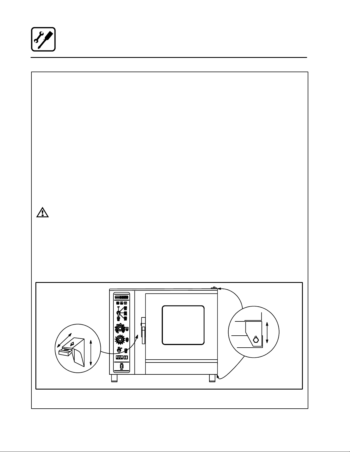
Oven Fea tures
7
Standard Features
8
10
3
9
2
Control Panel
1
2 Fuses, Power Supply
3 Oven Door
4 Drip Collector (self draining)
5 Door Handle
Figure 1
4
5
1
6 Door Contact Switch
7 Vent (not shown)
8 Decalcifying Inlet & Funnel Assembly
9 Decalcifying Valve Lever
10 Tilt Down Panel Screw
6
4
Page 9

1. Oven(s) are uncrated, stacked (if applies) and
put in place.
NOTE: Please refer to Leg Attachment and
Stacking Addendum.
2. The owner/operator must have the following
plumbing and electrical requirements met and
installed.
NOTE: Refer to the Utility Connection infor-
mation provided.
PLUMBING
Water
Water Pressure (min/max) 40 PSI min / 50 PSI max
Cold Water Connection 3/4” Hose Fitting, 3/8” ID hose minimum
Water Regulator Setting 35 PSI static
Mimimum requirements TDS --- less than 100 parts per million
Installation
Owner’s Responsibilities
WARNING!!
Improper installation, adjustment, alteration service or maintenance can cause
property damage, injury or death. Read
the installation, operation and maintenance instructions thoroughly before
installing or servicing this equipment.
Total Hardness --- 80-120 parts per million
Chlorides --- less than 30 parts per million
pH Factor --- 7.0-8.0
Drainage Atmospheric Vented Drain
Drain Connection 2” Copper
Avg Water Drain Temp. Approximately 122_F/50_C
ELECTRICAL
COS-6 COS-101 COS-101S
Electrical 9.4 kw 18.5 kw 18.5 kw
Amp/line (max) Amp/line (max) Amp/line (max)
3
Vol t
208 26 45 208 52 89 208 52 89
240 23 40 240 45 77 240 45 77
Blower Motor .33 HP / .4 kW .5 HP / .5 kW .5 HP / .5 kW
Phase1Phase
Vol t
480 23 N/A 480 23 N/A
3
Phase1Phase
Vol t
3
Phase1Phase
5
Page 10

Location
Installation
The well planned and proper placement of your
appliance will result in long term operator convenience and satisfactory performance.
The following clearances must be maintained between the unit and any combustible or non-combustible construction.
D Oven body right side --- 1” (2.54 cm)
D Oven body left side --- 4” (10 cm)
D Oven body back --- 6” (15 cm)
NOTE: For models with hose assemblies on the
back of the unit, the hose must be 1” (2.54
cm) from the wall.
The following clearances are recommended, but
not required, for servicing.
D Oven body sides --- 12” (30 cm)
D Oven body back --- 12” (30 cm)
Place the unit in an area which is free of drafts and
accessible for proper operation and servicing.
Keep the oven area free and clear of all combustibles such as paper, cardboard, and flammable
liquids and solvents.
DO NOT place the oven on a curb base or seal to
the wall; either condition will prevent proper ventilation to the blower motors. Slight unevenness can
be corrected with the adjustable legs.
Heat and water sources must not be located near
the air vents on the left side of the unit. Consult the
factory for an optional protective side heat shield
kit if a warm surface or water source is to the left
of the unit.
On all models, tripping the blower motor’s thermal
overload device indicates a n excessive ambient
temperature on the left side of the unit. This must
be corrected to prevent permanent damage to the
appliance. All motor bearings are permanently lubricated by the manufacturer; there is no need for
additional lubrication during the operational lifetime of the motors.
6
Page 11

Installation
Agency Approvals
THE INSTALLATION INSTRUCTIONS CONTAINED HEREIN ARE FOR THE USE OF QUALIFIED INSTALLATION AND SERVICE PERSONNEL
ONLY. INSTALLATION OR SERVICE BY OTHER
THAN QUALIFIED PERSONNEL MAY RESULT IN
DAMAGE TO THE OVEN AND/OR INJURY TO
THE OPERATOR.
Qualified installation personnel are individuals, a
firm, a corporation, or a company which either in
person or through a representative are engaged
in, and are responsible for:
D The installation of electrical wiring from the elec-
tric meter, main control box or service outlet to
the electric appliance.
Qualified installation personnel must be experiencedinsuchwork,befamiliarwithallprecautions required and have complied with all requirements of state or local authorities having
jurisdiction.
U.S. and Canadian Installations
Reference: National Electrical Code, ANSI/NFPA
70--- Latest Edition and/or Canadian Electrical
Code CSA C22.1 as applicable.
This equipment is to be installed in compliance
with the Basic Plumbing C ode of the Building Offi-
cials and Code Administrators International Inc.
(BOCA) and the Food Service Sanitation Manual of
the Food and Drug Administration (FDA).
General Export Installations
Installation must conform with Local and National
installation standards. Local installation codes
and/or requirements may vary. If you have any
questions regarding the proper installation and/or
operation of your unit, please contact your local
distributor. If you do not have a local distributor,
please call Blodgett Combi at 0011-802-860-3700.
7
Page 12
Installation
Utility Connections
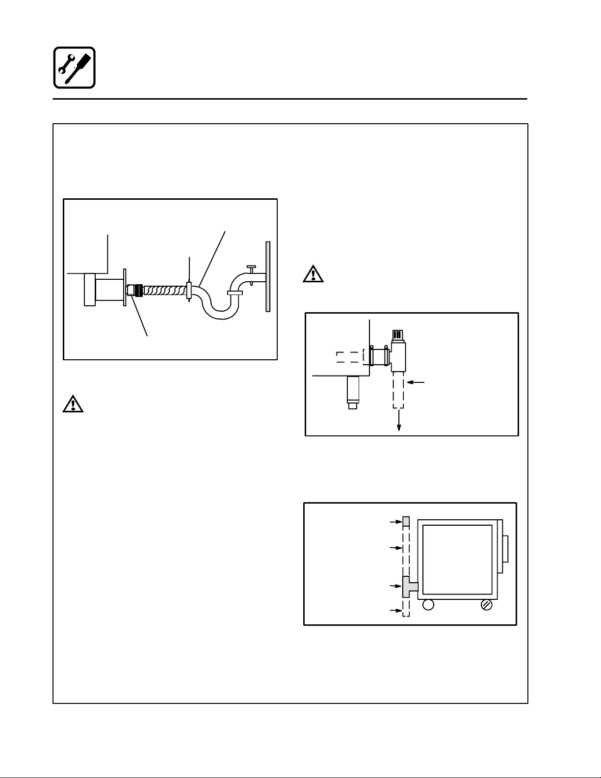
COLD WATER CONNECTION
Connect the appliance to quality water via a pressure hose with 3/4” couplings. A shut off valve is
to be provided adjacent to the oven.
1/2” appliance hose
with 3/4” hose fittings.
3/4” Coupling
Appliance
Solenoid
Washer
Figure 2
WARNING!!
The use of poor quality water will invalidate your warranty.
DRAIN CONNECTION
The Drain Vent assembly, included with the unit,
and a 2” (5 cm) copper pipe with standard drain
pitch, must be run to an open drain or connected
to a standpipe equipped with a vent.
NOTE: Thewastewatercanalsobedirectedtoa
nearby floor drain. Flexible hose which allows trapped water to accumulate in
sagged runs must be avoided.
WARNING!!
Failure to install the drain kit provided will
invalidate your warranty.
2” (5 cm) Drain
(Customer Supplied)
To Dr a i n
Figure 3
A 24” (61 cm) long standpipe must be connected
to the DWV. This allows the escaping water vapor
to exit above the inlet louvers on the back panel.
Breather Vent
Plumber Installed
Connection
Tee, Hose and Clamps
Plumber Installed
Connection To Drain
Figure 4
8
Page 13
ELECTRICAL CONNECTIONS
Before making any electrical connections to these
units, check that the power supply is adequate for
the voltage, amperage, and phase requirements
stated on the rating name plate mounted on the
right side of the unit.
U.S. and Canadian installations
All ovens, when installed, must be electrically
grounded in accordance with local codes, or in the
absence of local codes, with the National Electrical
Code, ANSI/NFPA 70 ---Latest Edition and/or Canadian National Electric Code C22.2 as applicable.
General export installations
Installation must conform with Local and National
installation standards.
Installation
Utility Connections
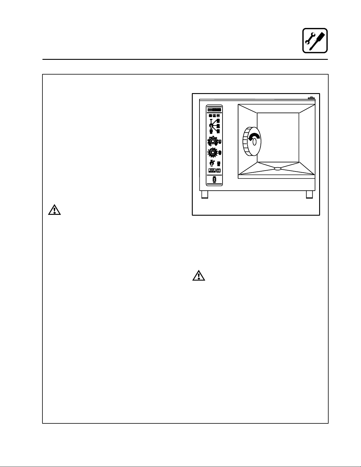
WARNING!!
On 480V units, the fan should be checked
to ensure the proper rotation after connecting the appliance. See Figure 5. If the
fan turns in the wrong direction, the appliance will not function properly and
damage to the unit can occur. Improper
connection of the appliance renders the
warranty invalid.
Direction Of Fan Rotation
Figure 5
NOTE: Disconnect the power supply to the unit
before servicing.
NOTE: All manual resets should be restored be-
fore connecting power to the appliance.
WARNING!!
Improper installation will invalidate your
warranty.
9
Page 14
Installation
Leg Attachment
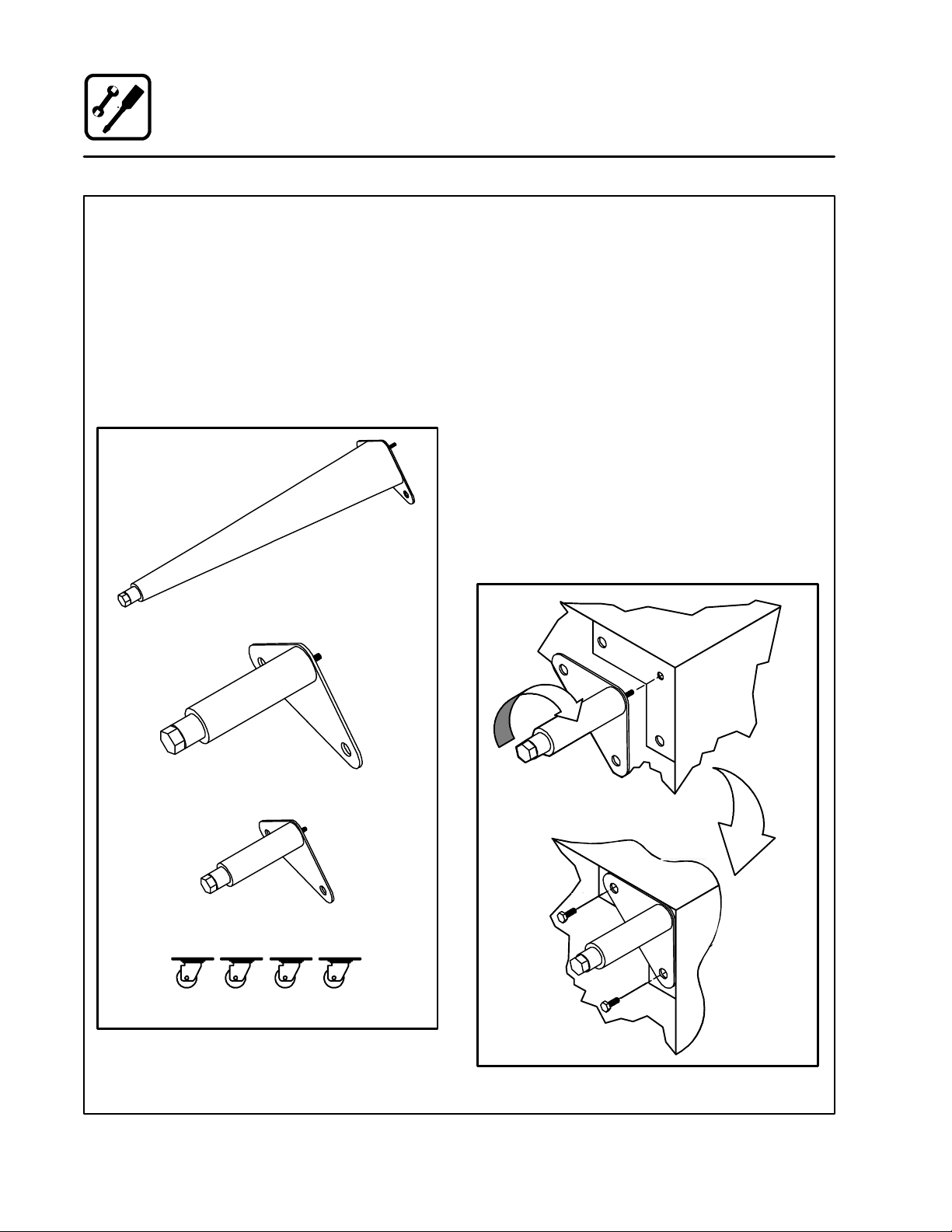
LEG VARIATIONS
Legs are available in 4” (101mm), 6” (152mm) or
25” (635mm) lengths or low profile casters. The 6”
legs are used on the lower section of a double
stacked unit. The 4” legs may be used with the optional stands if additional height is required or
when mounting on a counter. The 25” legs are
used for a single oven located on the floor.
NOTE: For safety reasons, casters must not be
used with the 25” legs.
25I Adjustable Leg
LEG ATTACHMENT
1. Align the threaded stud on one of the front
legs to the bolt hole located in the unit’s bottom corner. Turn the leg clockwise and tighten
to the nearest full turn.
2. Align the leg plate holes with the bolt holes.
Secure with the two 1/2” bolts provided.
3. Repeat the above steps with the other front
leg. If low profile casters are used, install them
with the locking casters in the front of the oven.
The rear casters do not lock. Ensure that the
locksaresetonthefrontcasters.
4. Tip the oven up on the newly installed front
legs. If casters are used, check that the locks
aresetonthefrontcasters.Repeat the above
steps for the rear legs.
5. Except for units w ith casters, level the oven by
screwing the adjustable feet in or out as necessary.
6I Ad justable Leg
4I Leg
Low Profile Casters
Figure 6
Figure 7
10
Page 15

Installation
Stacking
TO STACK TWO COS-6’S OR ONE COS-6 ON A
COS-101:
1. Install the 6” legs as directed.
2. Center a COS-6 unit on top of the lower section.
3. Remove the screws from the rear access panel and remove the access panel from the bottom unit.
4. Carefully remove the fan plug and disas semble the steam vent.
NOTE: The fan plug connector can be easily
damaged
5. Align the two rear bolt holes in the lower section with the two threaded holes in the upper
section.
6. Insert a bolt from the bottom up through each
of the two holes and tighten securely.
7. Reassemble the steam vent and reconnect
the fan plug. Reinstall the rear access panel
on the lower unit.
TO STACK A COS-6 ON A COS-101S:
1. Install the 6” legs as directed.
2. Place the COS-6 on top of the COS-101S.
Make sure that the front and left hand side of
the COS-6 line up evenly with the front and left
hand side of the COS-101S.
3. Remove the left side access panel from the
lower unit.
4. Thread one of the two supplied bolts up
through the COS-101S’s top rear frame member and into the bottom left rear corner of the
COS-6.
5. Thread the second bolt down through the bottom rear frame member of the COS-6 into the
nut welded to the frame member of the
COS-101S.
COS-6 on either
another COS-6 or a COS-101
Figure 8
COS-6 on a COS-101S
Figure 9
11
Page 16
Installation
Adjustments
BEFORE SWITCHING THE APPLIANCE ON
Before applying power to the unit for the first time,
check for the following conditions:
j All electrical safety provisions have been ad-
hered to and the electrical connections are
correct.
j The circulation fan turns counter-clockwise.
Check rotation from inside the oven cavity.
j Water is connected, turned on and all of the
connections are water tight.
j Thegreasefilterandholderareintheirproper
positions.
j The pan holders on models COS-6 and
COS-101 are inserted into the oven cavity.
Stationary rack guides are provided with the
COS-101S.
WARNING!!
If the fan turns in the wrong direction, the
appliance will not function properly and
can be damaged.
NOTE: When the unit is turned on, or after it has
been OFF for 5 hours and then turned on,
the steam generator automatically flushes
for 75 seconds. The steam generator then
fills to the proper water level. The unit is
now ready for operation.
DOOR ADJUSTMENT
The door latch may be adjusted in two directions,
in and out, and up and down, using the following
procedure:
1. Adjust up and down by loosening the two
bolts holding the latch to the face of the unit
(A).
2. Make adjustments so that t he leading face of
the latch is centered in the opening of the handle assembly.
3. Tighten the bolts so that there is no further
movement.
4. Adjust in and out by loosening the bolt on top
of the latch (B).
5. The adjustment face is stepped so that movement is limited with the bolt tightened properly .
6. The adjustment is correct when the door
closes firmly and no steam leaks from the gasket.
The hinges can also be adjusted as follows:
1. Be certain the latch is adjusted properly.
2. Adjust hinges so that the door back and the
unit face are parallel (C).
3. The adjustment is correct when no steam
leaks through the gasket.
Oven
B
Door
A
Figure 10
12
C
Page 17

Installation
Final Check Lists
ELECTRICAL CONTROL COMPARTMENT
Applied voltage to unit voltage/phase suitable for
appliance specified.
j Remove side panel
j Set motor protector (F2) to on position
j Adjust motor protector to maximum
j Reset high limit thermostats F3 and F6
j Check fuses
j Reinstall side panel
PLUMBING FINAL CHECK
j Incoming water pressure within 40 PSI (mini-
mum) --- 50 PSI (maximum)
j Atmospheric vented drain in place
j Water solenoid properly bracketed and not
leaking
j Water feed lines intact without leaks
j Water pressure regulator is set to 35 psi
j Optional spray hose connected properly
Washer
Regulator Assembly
“Y” Fitting
Cold water supply
Fill
Solenoid
Washer
OVEN OPERATIONAL TESTS
NOTE: Checkstobemadebycustomerorautho-
rized service agent.
Cool Down Mode
j Verify oven fan runs with door open
Combi Mode
Turn to COMBI mode, set thermostat to 350_F
(177_C) and verify:
j Boiler flushes and fills
j Boiler preheats to 185_F(85_C) then switches
to HOT AIR
j When HOT AIR reaches 350_F (177_C) HOT
AIR shuts off and STEAM comes on
Steam Mode
Turn on STEAM mode and verify (Control Panel
Removed):
j Check timer operation in all three positions
1. Set timer to OFF position, buzzer should
sound
2. Set timer in position other than OFF or
STAY ON, timer should count down
3. Set timer in STAY ON position, oven should
operate continuously without timer
j Run light (power light) turns on
j Unit produces steam, window fogs, door seal
does not leak
j Quenching system working
Hose and Spray
Spray Hose Connection
Figure 11
Hot Air Mode
Turn to HOT AIR mode and set thermostat to
400_F (205_C) and verify:
j Heat demand light is on
j Oven is heating properly
j Heat lights shuts off at 400_F (205_C) and
oven maintains 400_F (205_C)
13
Page 18

Operation
Oven Start-Up
STEAM MODE (if applicable)
1. Turn the mode selector switch to STEAM.
2. The green POWER Indicator lamp on the front
control panel lights.
3. The steam generator flushes and drain automatically for 75 seconds if the unit h as been off
for at least 5 hours.
4. The steam generator begins to fill. After tw o
minutes, the FILL indicator lamp on the front
control panel blinks. The convection blower
and POWER lamp turn off.
5. When the steam generator is filled to the proper level, the convection blower , interior lights
and POWER indicator lamp turn on.
6. Steam fills the cavity and is controlled by a
non-accessible internal thermostat.
HOT AIR MODE (if applicable)
1. Turn the mode selector switch to Hot Air.
2. The green POWER Indicator lamp on the front
control panel lights.
3. Set the hot air thermostat to the desired temperature.
4. The thermostat lamp lights, indicating the cavity temperature is below the desired set point.
5. When the cavity temperature reaches the desired set point, the temperature indicator lamp
goes off. The convection blower shuts off.
COMBI MODE (if applicable)
1. Turn the mode selector switch to COMBI.
2. The green POWER indicator lamp on the front
control panel lights.
3. Set the Hot Air thermostat to the desired temperature.
4. The steam generator flushes and drain automatically for 75 seconds if the unit h as been off
for at least 5 hours.
5. The steam generator begins to fill. After tw o
minutes the FILL indicator lamp on the front
control panel blinks. The convection blower
and POWER lamp do not shut down.
6. When the steam generator comes up to a predetermined temperature, the hot air thermostat lamp illuminates, indicating the cavity
temperature is below the desired set point.
7. When the cavity temperature reaches the desired set point, the temperature indicator lamp
goes off.
8. The steam and hot air burners toggle back
and forth responding to the thermostat set
points.
14
Page 19

Operation
Standard Controls
CONTROLS IDENTIFICATION
1. LOW WATER FILL LIGHT --- d u r i n g t h e f i l l
cycle, this light remains on until the water in
2
1
4
5
7
3
6
the steam generator is at the proper level and
up to temperature. During normal operation the
light should no t be o n. If the light comes on,
check the water level in the s team generator.
2. DON’T STEAM LIGHT --- indicates the unit is
too hot to operate in the steam mode. Place
the unit in the Cool Down mode until the tem perature is below 230_F (110_C) and open the
door. This light does not inhibit steam production.
3. POWER ON LIGHT --- indicates t he unit is in
Steam, Hot Air or Combi.
4. MODE SELECTOR SWITCH --- t u r n s p o w e r
to the oven on or off. Allows selection of
Steam, Hot Air, Combi or Cool Down Modes.
5. TEMPERATURE DIAL --- used to set desired
cooking temperature.
6. HEATING INDICATOR LIGHT --- li g h t s w h e n
the Hot Air heating is in operation.
7. TIMER DIAL --- used to set desired cooking
time.
8. FLUSH/DRAIN SWITCH --- used to flush/
drain the steam generator for decalcification.
8
Figure 12
15
Page 20

Operation
Standard Controls
OPERATION
1. Turn the MODE SELECTOR Switch (4) to the
desired function.
The POWER ON Light (3) illuminates.
2. Set the TIMER (7) for the desired cooking time
orsetittoSTAY ON. The buzzer sounds and
the unit shuts off when the time has expired.
3. For the HOT AIR and COMBI modes, set the
TEMPERATURE Dial (5) to the desired cook
temperature. The HEATING INDICATOR Light
(6) illuminates and stays lit until the desired
temperature is reached. The temperature dial
does not operate during the STEAM portion of
the COMBI mode.
4. The selected mode operates automatically.
Thetemperature,timeandmodecanbealtered at any time during the cooking process.
The operation can be stopped by the use of
the Mode Selector Switch or by opening the
door .
5. At the end of the specified time period, the
buzzer sounds and the appliance shuts off automatically. Move the TIMER (7) to the STAY
ON position to stop the buzzer and restart the
unit.
6. To cool down the oven cavity, switch the
MODE SELECTOR Switch (4) to COOL
DOWN. In the Cool Down mode neither the
temperature dial or the timer will be operational. The blower will function with the door open
or closed.
7. The mode selector switch is also the main
power switch. In the OFF position the appliance is not operational.
16
Page 21

10
11
13
15
Operation
Optional Cook & Hold
CONTROLS IDENTIFICATION
1. LOW WATER FILL LIGHT --- when lit indicates
low water level in the steam generator.
2. DON’T STEAM LIGHT --- when lit indicates
2
1
4
5
7
8
3
6
9
12
14
16
17
the unit is too hot to operate in the steam
mode.
3. POWER ON LIGHT --- when lit indicates pow-
er to the unit is turned on.
4. MODE SELECTOR SWITCH --- c o n t r o l s p o w -
er to the oven and selection of steam, hot air
and combi modes. The convection fan runs
with the switch in steam, hot air, combi or cool
down.
5. TIME DISPLAY --- gi v e s c o o k t i m e .
6. TIME ARROW KEYS --- press to enter cook
time from 00:00 to 99:59.
7. TEMPERATURE DISPLAY --- g i v e s c o o k t e m -
perature.
8. HEAT LIGHT --- when lit indicates hot air or
steam is in operation.
9. TEMPERATURE ARROW KEYS --- p r e s s to
enter cook temperature from 120 --- 212_F
( 4 8 --- 1 0 0 _C) for steam and 140 --- 500_F
( 6 0 --- 2 6 0 _C) for hot air/combi.
10. STAGE ONE LED --- when lit indicates opera-
tion or programming of stage one for the current product. Cook cycles may contain one or
two different stages.
11. ACTUAL TEMP KEY --- press to display actual
oven/steamer temperature
12. STAGE TWO KEY --- press to enter stage two
cook time and t emperature.
13. PRODUCT KEYS --- three programmable keys.
14. MANU AL PRODUCT KEY - -- default product
key used for manual and programmed cooking.
15. START KEY --- press to begin a cook cycle.
16. STOP KEY --- press t o silence audible alarms
and pause or cancel cook cycles.
17. PROGRAM KEY --- press to enter program-
ming mode and save programmed settings.
18. FLUSH/DRAIN SWITCH --- Used to flush/
drain the steam generator for decalcification.
Figure 13
17
Page 22

Operation
Optional Cook & Hold
MANUAL OPERATION
1. Turn the SELECTOR SWITCH (4) to the desired mode. The LED above the manual key
lights.
2. Press the TEMPERATURE ARROW KEYS (9)
to set the stage one cook temperature.
3. Press the TIME ARROW KEYS (6) to set the
stage one cook time.
4. Press the STA GE TWO KEY (12).
NOTE: Stage two can be used for either a
hold mode or a second cook temperature. Example: Cook meats or poultry
at a low temperature for maximum
moisture retention, then set the second stage for browning. To use the
second stage for holding, you must
set an appropriate hold time for the
unit to count down from.
NOTE: If stage two is not required enter a
cook time of 00:00.
5. Press the TEMPERATURE ARROW KEYS (9)
to set the stage two cook temperature.
6. Press the TIME ARROW KEYS (6) to set the
stage two cook time.
7. Press the START KEY (15) to begin the cook
cycle. The STAGE ONE LED (10) lights. The
TIME DISPLAY (5) counts down the stage one
cook time.
If stage two is selected an alarm sounds at the
end of stage one. The time display counts
down the stage two cook time.
8. When all cook stages are complete the TIME
DISPLAY (5) flashes 00:00, the TEMPERATURE DISPLAY (7) flashes 0 and an a udible
alarm sounds. Press the STOP KEY (16) to silence the alarm. The control maintains the
stage one cook temperature.
9. Turn the SELECTOR SWITCH (4) to OFF to
shut down the oven/steamer.
NOTE: Time and temperature settings may be
changed at any time during manual operation. Press the time arrow keys to change
the cook time. Press the temperature arrow keys to change the cook temperature.
PROGRAMMED OPERATION
NOTE: See page 19 for programming instruc-
tions.
1. Turn the SELECTOR SWITCH (4) to the desired mode.
2. Press the desired PRODUCT KEY (13). The
LED a bove the selected key lights.
3. Press the START KEY (15) to begin the cook
cycle. The STAGE ONE LED (10) lights. The
TIME DISPLAY (5) counts down the stage one
cook time.
NOTE: Press the STOP KEY (16) once to pause
an active stage one cycle. Press the
START KEY (15) to resume.
NOTE: Press the STOP KEY (16) twice to can-
cel an active stage one cycle.
4. An alarm sounds at the end of stage one The
time display counts down the stage two cook
time.
NOTE: Press the STOP KEY (16) once to can-
cel an active stage two cyc le. Stage
two cycles cannot be paused.
5. When all cook stages are complete, the TIME
DISPLAY (5) flashes 00:00, the TEMPERATURE DISPLAY (7) flashes 0 and an a udible
alarm sounds. Press the STOP KEY (16) to silence the alarm. The control maintains the
stage one cook temperature.
18
Page 23

Operation
Optional Cook & Hold
PROGRAMMING THE PRODUCT KEYS
NOTE: Each product key can hold two programs:
one for steam and one for hot air/combi. Hot
air programs can be used in combi.
1. Turn the SELECTOR SWITCH (4) to the desired mode.
2. Press the desired PRODUCT KEY (13).
3. Press and hold the PROGRAM KEY (17) for
five seconds. The control beeps. The product
key LED and STAGE ONE LED (10) light.
4. Press the TEMPERATURE ARROW KEYS (9)
to set the stage one cook temperature.
5. Press the TIME ARROW KEYS (6) to set the
stage one cook time.
6. Press the STA GE TWO KEY (12).
NOTE: Stage two can be used for either a
hold mode or a second cook temperature. Example: Cook meats or poultry
at a low temperature for maximum
moisture retention, then set the second stage for browning. To use the
second stage for holding, you must
set an appropriate hold time for the
unit to count down from.
NOTE: If stage two is not required enter a
cook time of 00:00.
7. Press the TEMPERATURE ARROW KEYS (9)
to set the stage two cook temperature.
8. Press the TIME ARROW KEYS (6) to set the
stage two cook time.
9. Press and hold the PROGRAM KEY (17) to
save the program settings.
PROGRAMMING THE MANUAL KEY
NOTE: The manual key may be used for manual
cooking and programmed for two products, one for steam and one for hot air/combi. Hot air programs can be used in combi.
1. Turn the SELECTOR SWITCH (4) to the desired mode.
2. Press the MANUAL KEY (14). The LED above
the manual key lights.
3. Press the TEMPERATURE ARROW KEYS (9)
to set the stage one cook temperature.
4. Press the TIME ARROW KEYS (6) to set the
stage one cook time.
5. Press the STA GE TWO KEY (12).
NOTE: Stage two can be used for either a
hold mode or a second cook temperature. Example: Cook meats or poultry
at a low temperature for maximum
moisture retention, then set the second stage for browning. To use the
second stage for holding, you must
set an appropriate hold time for the
unit to count down from.
NOTE: If stage two is not required enter a
cook time of 00:00.
6. Press the TEMPERATURE ARROW KEYS (9)
to set the stage two cook temperature.
7. Press the TIME ARROW KEYS (6) to set the
stage two cook time.
8. Press and hold the PROGRAM KEY (17) to
save the program settings.
NOTE: Time and temperature settings may be
changed at any time during operation of a
programmed manual key. Press the time
arrow keys to change the cook time. Press
the temperature arrow keys to change the
cook temperature.
19
Page 24

Operation
Optional Meat Probe
CONTROLS IDENTIFICATION
1. MEAT PROBE SWITCH
Controls power to the meat probe.
2. MEAT PROBE CONTROL
Use to set the desired probe temperature. Indicates the actual temperature of the product
3. MEAT PROBE CONNECTOR
Receptacle for the plug in meat probe.
NOTE: For sanitation it is recommended that
the meat probe remain plugged into
the front panel receptacle at all times.
OPERATION
Measuring the product core temperatures during
long roasting periods is very practical. It is especially important for products such as Roast Beef to
reach a specific internal temperture.
Place the probe through to the middle of the product’s thickest section. B e sure the probe does not
touch any bone and the tip is not in a fat pocket.
These conditions can ca use inaccurate readings.
1. Set the MODE SELECTOR Switch to the desired function.
2. Turn the MEAT PROBE Switch (1) to ON.
3. To set the desired core temperature press the
blue SET BUTTON (4) on the MEAT PROBE
CONTROL (2).
Use the up arrow key (6) to increase the setpoint temperature. Use the down arrow key
(5) to decrease the setpoint temperature.
Press the set button again to store the setpoint.
4. Set the TIMER to STAY ON. The cooking process runs automatically.
When the selected core temperature is
reached, the buzzer will sound and the ap pliance shuts off automatically.
The temperature and mode can by changed
at any time during the process.
5. Shut the appliance off by setting the mode
switch to OFF.
NOTE: When setting the internal temperature, be
sure to allow for carry-over cooking after
the roast is removed from the oven.
1
2
3
Figure 14
20
WATLOW
1
2
RDY
SET
4 5 6
Page 25

Maintenance
Spray Bottle Operating Procedure
1. Unscrew the sprayerhead and fillthe container to the MAX mark. Screw the head assembly
on firmly to ensure an airtight seal. The liquid
must be clean and free from foreign matter. Do
not overfill - space must be left for compressing air.
2. Tobuilduppressure,pumpapproximately20
full strokes when the container is filled with liquid. The higher the pressure, the finer the
spray. If the container is only partially filled,
then more pumping is required to compress
the additional air space.
3. To spray, depress the trigger with your thumb.
4. After a period of spraying, the pressure will
drop. Restore the pressure by operating the
air pump.
5. Release pressure after use by inverting the
spray head and depressing the trigger or by
slowly unscrewing the spray head assembly
which will allow air to escape from around the
filling aperture.
6. After use, rinse the spray bottle with clean water and check that the hole in the nozzle is perfectly clean and clear. Warm water (not hot)
used with a household detergent is a useful
cleaning agent for this purpose.
NOTE: Further information can be found in the in-
struction leaflet supplied with your spray
bottle.
Service Parts:
Complete spray bottle P/N R0006
Spray nozzle repair kit P/N R6332
WARNING!!
Protective clothing and eye wear should
be worn while using cleaning agents.
Pressure Pump
Spray Head
Pump
MAX
Pressure
Vessel
Clean the pump 2 or 3 times per week with warm water
Spray Trigger
Figure 15
21
Page 26

Maintenance
Cleaning and Preventive Maintenance
CLEANING THE INTERIOR
Daily cleaning of the appliance is essential for sanitation and to ensure against operational difficulties. Use an oven cleaning detergent in conjunction with the supplied spray bottle.
On stainless interiors, deposits of baked on splatter, oil, grease or light discoloration may be removed with a good non toxic industrial stainless
steel cleaner. Apply cleaners when the unit is cold
and always rub with the grain of the metal. The
racks, rack supports and the blower wheel may be
cleaned either in the unit or removed and soaked
in a solution of ammonia and water.
NOTE: DO NOT use corrosive cleaners!
1. Cool the appliance down to 140_F(60_C) or,
if the unit has been idle, turn the steam mode
on for 3 to 4 minutes in order to warm the interior surfaces.
2. Fill the spray bottle and pump air into the container w ith the pressure pump.
3. Spray the interior of the unit with a cleaning solution.
NOTE: Never spray water into the unit when
the temperature is above 212_F.
NOTE: NEVER SPRAY WATER IN THE UNIT
AFTER USING THE HOT AIR OR COMBI MODES.
4. Let the cleaner work for 10 to 20 minutes with
the unit off. For difficult cleaning allow to work
over night.
5. Set the timer for 15 to 20 minutes. Turn the
mode selector switch to Steam. This will soften all burned on residue.
6. Rinse the interior with the hose and spray as sembly.
7. Setthe mode selector to steam for another five
minutes to flush out the interior a nd remove all
detergent residue.
NOTE: The interior cavity should never be
scoured or scraped.
CLEANING THE EXTERIOR
Exteriors may be cleaned and kept in good condi tion with a stainless steel polish.
NOTE: DO NOT spray the outside of the appliance
with water.
PREVENTIVE MAINTENANCE
The best preventive maintenance measures are:
D the proper initial installation of the equipment
D deliming the steam generator (if applicable)
D a program for routine cleaning.
These units requires no lubrication. Contact the
factory, a factory representative or a local Blodgett
Combi service company to perform maintenance
and repairs should they be required.
WARNING!!
Disconnect the appliance from the power
supply before servicing or cleaning.
22
Page 27

Maintenance
Decalcification
1. TurntheModeSelectionSwitch(1)tothe
STEAM mode. Wait until steam is produced.
This will ensure that the water in the steam
generator is hot.
2. TurntheModeSelectionSwitch(1)tothe
COOL DOWN mode and leave the door open.
Let the oven compartment cool to 150_F
(66_C). This ensures that the Drain/Flush
switch will function in STEP 8.
3. TurntheModeSelectionSwitch(1)toOFF.
4. In a suitable size container, mix together the
deliming solution and hot tap water. Refer to
the following chart for the proper mixture:
Deliming
Model
COS-6 12 oz. 3quarts
COS-101 18 oz. 1-1/4 gallons
COS-101S 18 oz. 1-1/4 gallons
NOTE: These volumes are approximate. You
may need more or less hot water depending on your site.
5. Remove the Deliming Port Cap from the De-
liming Inlet (5). Attach the supplied Funnel
and Hose Assembly (3) to the deliming inlet.
6. Open the Deliming Port Valve (2) and pour in
the deliming mixture. Stop pouring when the
funnel stops draining. This is the correct
amountforyoursite.
Solution
Hot Tap Water
7. Shut the Deliming Port Valve (2). Screw on the
Deliming Port Cap. Let the mixture stand for 20
minutes. In areas of the country with hard water, allow the mixture to stand for 1 hour.
8. Depress and hold the Drain/Flush Switch (4)
in the FLUSH position for 90 seconds. This
completes the deliming procedure.
3
2
1
5
open
close
4
Figure 16
23
Page 28

Introduction
Le Combi-four/étuve à vapeur Blodgett
Depuis un certain temps le matériel de cuisson
commerciale est resté plus ou moins inchangé. Il
y a des bouilloires, des fours ouverts, des bonnes
vieilles cuisinières avec leurs régiments de casseroles et de nombreux autres appareils. Le résultat:
gaspillage de temps, excès de travail manuel, et
des processus de nettoyage interminables. Ces
quelques dernières années ont préparées la voie
pour une révolution dans l’équipement des cuisines de restaurants et de collectivités.
Le Combi-four/étuve à vap eur de Blodgett offre
une entièrement nouvelle méthode pour cuisiner.
Avec le Four-étuve à Vapeur vous avez le choix
entre deux procédés de cuisson: À la vapeur et
àl’airchaud, soit...
D Séparèment
D En combinaison, ou
D En séquence
Et pour faciliter le fonctionnement vous pouvez
choisir entre trois modes:
Vapeur Air Chaud Combi
Vapeur et
Air Chaud
En mode Vapeur vous pouvez:
D cuire à la vapeur D blanchir D pocher
D décongeler D thermaliser
En mode Air chaud vous pouvez:
D rotir D cuire au four D braiser
En mode Combinaison vapeur et air chaud vous
pouvez:
D décongeler D rotir D thermaliser
D réchauffer D cuire au four D sous vide*
D apprêter* D cuisson et pause*
* avec commandes numériques en option
Non seulement cela, mais en plus vous pouvez utiliser deux ou trois fonctions en séquence au cours
d’un processus de cuisson. Nous appelons cela:
D Combi-vapeur
D Combi-rôtir
D Combi-au four
La combinaison de l’air chaud et de la vapeur circulants dans l’espace réduit du Combi-four/étuve
à vapeur de haute performance apporte des
améliorationsdansleszonesd’influencesuivantes:
D productivité augmentée dans la cuisine
D réduction des dépenses de remplacement de
multiples appareils
D une plus grande gamme de choix pour les me-
nus
D un processus de nettoyage simplifié
Le processus de travail est simplifié puisque les
aliments sont préparés sur ou dans des pots et
des plats pour table chaude. La nourriture peut
être cuîte, rangée et transportée dans les mêmes
ustensiles. Des petites quantités d’aliments peuvent être traitées efficacement ; plats préparés et
aliments pratiques peuvent être réchauffés en
quelques minutes. La plupart des aliments congelés peuvent être traités sans avoir été décongelés.
Cette flexibilité de préparation diminue le besoin
de bainsmarie et de tables chaudes pour garder
la nourriture à la bonne température pendant de
longues périodes de temps.
Aujourd’hui l’amélioration de la qualité de la nourriture est plus importante que jamais. Les légumes
cuits s ans eau dans le Combi-four/étuve à vapeur
de Blodgett à la température optimale de juste audessous de 100_C (212_F) qui conserve les vitamines et les minéraux importants, les substances
nutritives et autres éléments. La cuisson de la
viande dans le Combi donne un produit plus
ferme, plus juteux et moins réduit. Le Combi-four/
étuve à vapeur de Blodgett est de plus en plus utilisé pour la cuisson au four. Les modes Vapeur et
Air chaud en font un four à usage général.
24
Page 29

Introduction
Description du Combi-four/étuve à vapeur
AU SUJET DU FOUR/ÉTUVE À VAPEUR
Les Combi-four/étuve à vapeur sont des produits
de qualité, fabriqués avec des aciers inoxydables
de haut grade par une main d’oeuvre de première
classe.
Le générateur de vapeur fraîche à haute performance, avec son s ystème de commande, permet
de profiter de tous les avantages d’une étuve à vapeur de haute qualité par le simple mouvement
d’un interrupteur. Une vapeur fraîche entre dans le
four sans pression et circule à haute vitesse. Ce
procédé permet une cuisson rapide et douce qui
assure des nourritures de haute qualité tout en offrant des méthodes pratiques de travail. Le générateur de vapeur et complètement automatique et
il est protégé contre le fonctionnement à sec.
Un système éliminateur breveté garde l’air du four
propre. Les exhalaisons qui s’échappent pendant
que les aliments rôtissent ou grillent sont aspirées
hors de l’appareil, éliminées et sorties par l’intermédiaire du tube de condensation. Le système
d’évacuation est efficace dans tous les modes de
cuisson et a pour résultat une meilleure qualité
desalimentssanstransfert de goût.Leventilateur qui est protégé contre tout contact accidentel
avec les doigts est actionné par un moteur puissant et silencieux. Le tube de condensation retire
les excès de vapeur de l’appareil. Condensation
et eau perdue qui sont le résultat de la cuisson étuvée et du nettoyage s’écoulent continuellement.
L’usage d’une isolation de haute qualité empêche
une radiation thermique excessive et économise
l’énergie.
Le Four/étuve à Vapeur a des pieds réglables, en
option, qui s’adaptent facilement sur les surfaces
légèrement inégales et, également en option, des
bâtis d’ assise au sol qui sont conçus pour être utilisésavectouslesmodêlesdetable.
FONCTIONNEMENT FOUR/ÉTUVE À VAPEUR
La porte du four pratique avec fenêtre a un large
rayon d’ouverture et une poignée qui fonctionne
facilement même avec des mains mouillées ou
graisseuses.
La facilité de fonctionnement est garantie par le
simple arrangement des commandes. Les symboles graphiques facilitent l’usage du four, même
par des employés de cuisine sans expérience. Les
modes vapeur, air chaud et combi peuvent être
choisis à partir d’un seul commutateur. Une quatrième fonction sur le commutateur de sélection
de mode, le mode de refroidissement, permet à
l’intérieur du four de se refroidir rapidement que la
porte soit ouverte ou fermée.
Le nettoyage est minimal. L’intérieur est vaporisé
avec une solution de nettoyage auto-active qui interagit avec la vapeur pour enlever facilement les
croutes et les taches. Le four est conçu pour un
entretien facile et il est soudé étanche ce qui permet de rincer l’intérieur du four avec un jet d’eau
après le processus de nettoyage à la vapeur.
25
Page 30

Introduction
Caractéristiques du four
7
Caractéristiques standard
8
10
3
9
2
Panneau de commande
1
2 Fusibles, Connexion électrique
3 Porte du four
4 Collecteur d’égouttement
(amovible pour nettoyage)
5 Poignéedelaporte
Figure 1
4
5
1
6 Interrupteur du contact de la porte
7 Ventilation (pas montré)
8 Entrée de détartrage et assemblage
entonnoir
9 Levierdelasoupapededétartrage
10 Les bouchons amovibles permettent d’ ac-
céder aux vis qui maintiennent le bac de récupération.
6
26
Page 31

1. Les fours sont sortis de leurs caisses d’emballage, empilés (le cas échéant) et mis en place.
REMARQUE:Consultez les informations four-
nies dans les sections Fixation
des pieds et Superposition.
2. Le propriétaire/utilisateur doit remplir les con ditions de plomberie et d’électricité suivantes.
REMARQUE:Consultez les informations four-
nies dans la section Branchements utilitaires.
PLOMBERIE
Eau
Pression de l’eau (min/max) 40 PSI min / 50 PSI max
Provision pour eau froide Raccord de tuyau de 3/4 po, 3/8 po de
Réglage du régulateur de pression 35 psi statique
Installation
Responsabilités du propriétaire
AVERTISSEMENT!!
Unemauvaiseinstallation,unmauvaisré-
glage, l’apport de modi fic ati ons inadéquates ou un mauvais entretien de cet appareil peuvent entraîner l’endommagement
du matériel ainsi que des blessures graves,
voire mortelles. Lisez soigneusement les
instructions d’installation, d’utilisation et
d’entretien avant d’installer ou de procéder
à l’entretien de ces appareils.
diamètre intérieur (d.i) min
Conditions requises minimum Total des solides en suspension (TDS) --- doit
être moins que 100 parties par million
Dureté totale de l’eau - -- 80-120 parties par million
Chlorides --- doit être moins que 30 parties par
million
Le pH de l’eau --- 7.0-8.0
Drainage Drain mis à l’air libre
Raccordement du drain 2poencuivre
Température moyenne de l’eau drainée A peu près 50_C (122_F)
CARACTÉRISTIQUES ÉLECTRIQUES
COS-6 COS-101 COS-101S
Électrique 9.4 kw 18.5 kw 18.5 kw
A/ligne (max.) A/ligne (max.) A/ligne (max.)
VAC 3Ô 1Ô VAC 3Ô 1Ô VAC 3Ô 1Ô
208 26 45 208 52 89 208 52 89
240 23 40 240 45 77 240 45 77
480 23 N/A 480 23 N/A
Moteur de Ventilateur .33 HP / .4 kW .5 HP / .5 kW .5 HP / .5 kW
27
Page 32

Installation
Placement
Un emplacement correct et soigneusement prév u
pour l’appareil aura pour résultat, à long terme, une
utilisation pratique et un rendement satisfaisant.
Les espaces de dégagement ci-dessous doivent
être prévus entre le four et les munis d’assemblages et toute construction combustible ou non.
D Côté droit du four --- 2.54 cm (1 po)
D Côté gauche du four--- 10 cm (4 po)
D Arrière du four --- 15 cm (6 po)
REMARQUE:Pour les modèles munis d’assemb-
lages de tuyaux à l’arrière de l’appareil, le tuyau doit se trouver à 6 po (15
cm) du mur.
Les espaces de dégagement ci-dessous doivent
être possible pour permettre l’entretien.
D Côté du four --- 30 cm (12po)
D Arrière du four --- 30 cm (12po)
Placer le four dans une zone sans courants d’air
et accessible pour permettre son fonctionnement
et son entretien.
Garder la zone du l’appareil libre et dégagée de
toutes matières combustibles, telles que papiers,
cartons, liquides inflammables et solvants.
NE PLACEZ PAS l’appareil sur un socle courbé, et
ne le fixez pas au mur. Dans ces deux cas, les moteurs à soufflerie ne pourraient pas être convenablement ventilés. Une petite dénivellation peut se
corriger avec les pieds réglables.
Les grilles d’aération situées du côté gauche le
l’appareil doivent être protégées de la chaleur, de
la vapeur et des sources d’eau. Consultez le fabricant pour obtenir un bouclier thermique, en option, si la chaleur ou la vapeur ambiante affecte le
côté gauche de l’appareil.
Sur tous les modèles : le déclenchement du dispositif de surcharge thermique des moteurs à soufflerie
indiquequelatempératureambianteàl’arrièredu
four est trop élevée. Cette température doit être corrigée afin d’empêcher que le four ne soi t irrémédiablement endommagé. Tous les paliers de moteur
sont lubrifiés en permanence à l’usine; ils ne nécessitent aucune lubrification supplémentaire pendant
la durée de vie opérationnelle des moteurs.
28
Page 33

Installation
Normes et Codes
LES CONSEILS D’INSTALLATION ET D’ENTRETIEN CONTENUS DANS CE MANUEL NE
S’ADRESSENT QU’Á UN PERSONNEL QUALIFIÉ. UN PERSONNEL NON QUALIFIE PEUT SE
BLES SER ET/OU ABÎMER LE FOUR LORS DE
SON INSTALLATION ET/OU SON ENTRETIEN.
Un personnel d’installation qualifié est représenté
soit par des personnes physiques, soit par un société, une usine, une corporation qui en personne
ou par l’intermédiaire d’un représentant s’engage
à et est responsable de:
D l’installation du câblage électrique reliant le
compteur d’électricité, l’armoire électrique ou la
prise de courant à l’appareil électrique.
Le personnel d’installation qualifié doit être expérimentédanscetypedetravail,s’êtrefamiliarisé
avec toutes les précautions requises et respecter
tous les réglements promulgués par les autorités
provinciales ou locales compétentes.
Installations aux États-Unis et au Canada
L’installation doivent être en accord avec les codes
locaux, ou en l’absence de codes lo caux, avec le
Code Électrique National (National Electrical Code),
ANSI/NFPA 70- --Dernière éditio n et/or Code Électrique Canadien CSA C22.2 si applicable.
Cet équipement doit être installé en respectant les
normes du code de base de la plomberie des pro fessionnels du bâtiment américain et du code international des administrateurs (Basic Plumbing
Code of the Building Officials and Code Administrators International Inc (BOCA),) ainsi que celles
du manuel de l’hygiène de l’industrie de la restauration du secrétariat américain aux produits alimentaireset pharmaceutiques[Food ServiceSanitationManual of the Food and Drug Administration
(FDA)).
Installationsdesappareilsexportés
L’installation doit suivre les normes locales et nationales. Les codes d’installatio n et/ou les exigences
peuvent varier d’une localité à l’autre. Si vous avez
des questions portant sur l’installation et/ou l’utilisation adéquate de vo tre four Blodgett, veuillez contacter votre distributeur local. Si aucun distributeur
local n’est situé dans votre localité, veuillez appeler
Blodgett Combi au 0011-802-860-3700.
29
Page 34

Installation
Branchement Utilitaires
BRANCHEMENT D’EAU FROIDE
Brancher l’appareil sur une arrivée d’eau froide de
qualité à l’aide du tuyau de pression ayant un raccord de 19 mm (3/4 po). Une vanne de fermeture
doit être prévue à proximité du four.
Tuyau de l’appareil de 1,3 cm (12 po)
avec raccords de 1,9 cm (3/4 po)
Raccord
Solenoide
de l’appareil
Rondelle
Figure 2
AVERTISSEMENT!!
L’usage d’eau de mauvaise qualité an-
nule la garantie.
BRANCHEMENT DU TUBE D’ÉCOULEMENT
Untuyaude5cmavecunepentedevidangestandard doit aller jusqu’à un puisard ou être connecté
sur une colonne descendante équipée d’un évent.
REMARQUE:Les eaux perdues peuvent aussi être
dirigées vers un écoulement au sol
proche.Si un tuyau flexible est utilisé,
s’assurer qu’il n’a pas de longueur
pendant où les eaux usées peuvent
s’accumuler.
AVERTISSEMENT!!
Négliger d’installer le kit de purge annule
la garantie.
Écoulement de
5cm(2po)fournit
par l’utilisateur
Ver l’écoulement
Figure 3
Un conduit de descente de 60 cm (24 po) de longueur doit être branché sur le tuyau d’évacuation.
Ceci permet aux vapeurs d’eau qui se dégagent
de sortir au-dessus des ouïes qui sont sur le panneau arrière.
Orifice de Respiration
Branchement installé
par un plombier
“T”, Tuyau et brides
Branchement sur
écoulement, installé par
un plumbier
Figure 4
30
Page 35

BRANCHEMENTS D’ÉLECTRICITÉ
Avant toutes connexions électriques de ces unités, vérifier que l’alimentation électrique est adéquate pour le voltage, l’ampérage et la phase demandés sur la plaque signalétique du
constructeur qui est montée sur l’unité.
Installations aux États-Unis et au Canada
Au moment de l’installation, tous les fours doivent
être électriquement mis à la terre en accord avec
les codes locaux ou, en l’absence de codes locaux, avec le Code Électrique National (National
Electrical Code), ANSI/NFPA 70---Dernière édition
et/orCodeÉlectriqueCanadienCSAC22.1siapplicable.
Installationsdesappareilsexportés
L’installation doit suivre les normes locales et nationales.
Installation
Branchement Utilitaires
Direction de l’éventaille
AVERTISSEMENT!!
480V modèles: s’assurer de la rotation
des éventailles. Voir le Figure 5. Si les
éventailles tournent dans l a mauvaise direction, il y aura possibilité d’endomager
lefour.Silefourn’aipasbrancherproprement, l’annulation de la garantie sera
omit.
Figure 5
REMARQUE:Débrancher l’appareil de l’alimenta-
tion électrique avant le service.
REMARQUE:Tous les règlement de sécurité deu-
rais être vérifier avant de brancher le
courant à l’appareil.
AVERTISSEMENT!!
Une installation défectueuse invalide la
garantie.
31
Page 36

Installation
Fixation des pieds
VARIATIONS DE PIEDS
Des pieds sont disponibles en des longueurs de
10,1 cm (4 po), 15,2 cm (6 po) ou 63,5 cm (25 po)
ou en roulettes de profil bas. Les pieds de 15,2 cm
sont utilisés sur le four inférieur d’une doubleunité
superposée. Les pieds de 10,1 cm peuvent être
utiliséssur les bâtis (en option) si une hauteur supplémentaire est nécessaire ou lorsdu montage du
four sur un comptoir. Les pieds de 63,5 cm sont
utilisés pour un four unique posé au sol.
REMARQUE:Pour des raisons de sécurité, les rou-
lettes ne doivent pas être utilisées
avec les pieds de 63,5 cm (25 po).
Pied Réglable de 63,5 cm (25 po)
FIXATION DES PIEDS
1. Aligner le goujon fileté de l’un des pieds avant
sur le trou de vis situé au coin inférieur de l’unité. T ourner le pied dans le sens des aiguilles
d’une montre et serrer jusqu’au tour complet
suivant.
2. Alignerlestrousdelaplaquedupiedsurles
trous de vis. Assujettir avec les deux boulons
de 12,7 mm (1/2 po) fournis.
3. Répéter les étapes ci-dessus avec le deuxième pied avant. Sidesroulettesdebasprofil
sont utilisées, les installer en utilisant les roulettes à freins. Les roulettes pour l’arrière du
four n’ont pas de frein. S’assurer que les
freins sont bl oqués sur les roulettes avant.
4. Basculer le four sur les pieds avant qui viennent d’être posés. Si des roulettes sont utili-
sées, vérifier que les freins sont bloqués sur
les roulettes avant. Répéter les étapes ci-des-
sus pour les pieds arrières.
5. Sauf pour les unités avec roulettes, mettre le
four à niveau en vissant ou dévissant, s uivant
besoin, la vis de mise à niveau du pied.
PiedRéglablede15,2cm(6po)
Piedde10,1cm(4po)
Roulettes de bas profil
Figure 6
Figure 7
32
Page 37

Installation
Superposition - Assemblage section double
POUR SUPER-POSER DEUX COS-6’S OU UN
COS-6 SUR UN COS-101:
1. Installerlespattesde15cm(6po)commerecommander.
2. Centrer le COS -6 au-dessus de l’unité du bas.
3. Enlever les vis de l’accés arrière des deux unités.
4. Débrancher la connection de l’éventaille, puis
déassembler le ventillateur d’ébullision.
REMARQUE:La connection de l’éventaille,
peut-être facilement endomager.
5. Aligner les deux trous dans la section du bas
avec les deux trous filer de la section du haut.
6. Inserrer les vis du bas vers le haut dans chacun des troue, puis serrer prompement.
7. Rassembler le ventillateur d’ébullition et
brancher l’éventaille, installer le panneau
d’accès arrière sur l’unité du bas.
POUR SUPER-POSER UN COS-6 OU UN
COS-101S:
1. Installerlespattesde15cm(6po)commerecommander.
2. Placer le COS-6 dessus le COS-101S. Soyer
sûr que le devant et le côte gauche du COS-6
soit égallement aligner avec le devant et le
côte gauche du COS-101S.
3. Retirer le panneau d’accès gauche de l’unité
du bas.
4. Prendre une des deux vis fournis. Afiler dans
le haut du coin derrière du COS-101S’s avec
lebasducoingaucheduCOS-6.
5. Prendre la deuxième vis, afiler dans le bas du
chasis du COS-6 dans la noix souder à l’intérieur d u COS -101S.
COS-6 sur/ou COS-6 ou COS-101
Figure 8
COS-6 sur un COS-101S
Figure 9
33
Page 38

Installation
Vérification finale et derniers réglages
AVANT DE METTRE L’APPAREIL EN MARCHE
Avant de mettre l’appareil sous tension pour la
première fois, vérifier les conditions suivantes:
j Tous les réglements de sécurité électrique ont
étéappliquésettouteslesconnexionsélectriques sont correctes.
j L’éventaille devrait tourner dans le sense in-
verse des aiguilles, vérifier la direction par
l’ouverturedelacavitée.
j L’eau est branchée, ouverte et tous les rac-
cords sont étanches.
j Le filtre à graisse et son soutien, soit à leur
position.
j Les lèchefrites des modelsCOS-6 et COS-101
sont inserrer dans la cavitée. Grilles stationnaires son fournis avec le model COS-101S.
AVERTISSEMENT!!
Si les éventailles tournent dans la mau -
vaisedirection,lefournefonctionnera
pas propement, et il y aura possibilité
d’endomagement.
REMARQUE:La première fois que l’unité est mise
sous tension, ou quand l’unité a été à
l’ARRÊT pendant 5 heures ou plus,
puis rallumée, elle vidange automatiquement le générateur de vapeur
pendant une période de 45 secondes. Le générateur de vapeur se
remplit alors au niveau correct.L’unité est alors prête pour fonctionner.
RÉGLAGEDELAPORTE
Le loquet de la porte peut être réglé dans deux directions, vers l’intérieur ou l’extérieur et vers le
haut ou le bas, en suivant le procédé ci-dessous:
1. Régler le loquet vers le haut ou le bas en desserrant les deux vis qui tiennent le loquet sur
le devant de l’unité (A).
2. Faireceréglagedefaçonàcequelaface
avant du loquet soit centrée dans l’ouverture
de l’assemblage de la poignée.
3. Resserrerles vis jusqu’à ce qu’il n’y ait plus de
mouvement.
4. Régler le loquet vers l’intérieur ou l’extérieur
en desserrant la vis qui est sur le dessus du loquet (B).
5. La face de réglage est à échelons et donc le
mouvement est limité quand la vis est correctement serrée.
6. Le réglage est correct quand la porte ferme
serrée et qu’aucune vapeur ne s’échappe par
le joint.
Les charnières peuvent aussi être réglées comme suit:
1. S’assurer que le loquet est correctement ajusté.
2. Régler les charnières pour que l’intérieur de la
porte soit parallèle avec le devant de l’unité (C).
3. Le réglage est correct quand aucune vapeur
ne s’échappe par le joint.
FOUR
B
C
A
Réglagedelaporte
Figure 10
34
PORTE
Page 39

Installation
Vérifications Finales
BOÎTIER DES COMMANDES ÉLECTRIQUES
Le voltage utilisé pour le voltage/phase de
l’appareil correspond à l’appareil qui a été
spécifié.
j Enlevez le panneau latéral
j Réglez les dispositifs de protection du moteur
(F2) sur MARCHE (ON)
j Réglez les dispositifs de protection du moteur
sur maximum
j Réglez à nouveau les t hermostats sur la limite
maximum (F3 et F6)
j Vérifiez les fusibles
j Remontez le panneau latéral
VÉRIFICATION FINALE DE LA PLOMBERIE
j La pression d’eau entrante doit se situer entre
40 PSI (minimum) --- 50 PSI (maximum)
j Le système de purge atmosphérique est en
place
j Les électrovannes d’eau sont correctement
encadrées et ne coulent pas
j Les conduites d’alimentation en eau ne fuient
pas
j Le régulateur de pression d’eau est réglé à 35
psi.
j Le tuyau d’arrosage est correctement branché
Rondelle
Ensemble du régulateur
Raccord en “Y”
Alimentation en
Électrovanne de
remplissage
Rondelle
Tuyau et embout
d’arrosage
Le tuyau d’arrosage
Figure 11
eau froide
TESTS DE FONCTIONNEMENT DU FOUR
REMARQUE
REMARQUE:Ces vérifications doivent être effec-
tuées par le client ou par le prestataire de services agréés.
Mode refroidissement (le cas échéant)
j Réglez l’interrupteur sur REFROIDISSEMENT
(COOL DOWN), et assurez-vous que le moteur fonctionne lorsque la porte est ouverte.
Mode Combi (le cas échéant)
Mettez l’appareil en mode Combi, réglez le thermostat sur 177_C (350_F) et vérifiez que :
j Le générateur de vapeur se vide et se remplit
j Le générateur de vapeur préchauffe à 175_F
(79_C), puis passe en mode air chaud
j Lorsque l’air chaud atteint les 177_ C (350_F),
sa production est remplacée par de la vapeur
Mode vapeur (le cas échéant)
Enlevez le panneau de commandes, réglez l’appareilsurlemodeVAPEUR(STEAM)etvérifiez:
j Chaque position du minuteur
1. Régler le minuteur à l’arrêt (OFF); l’alarme
devrait sonner.
2. Réglez le minuteur sur une position autre
que ON ou STAYON, il devrait entamer un
compte à rebours
3. Réglez le minuteur sur ON, le four devrait
fonctionner de façon continue sans minuteur.
j Le voyant marche s’allume
j L’appareil produit de la vapeur, les fenêtres
s’embuent, le dispositif d’étanchéité de la
portenefuitpas.
j Le système de refroidissement fonctionne
Mode Air chaud (le cas échéant)
Réglez le four sur AIR CHAUD (HOT A IR), réglez
le thermostat sur 205_C (400_F) et vérifiez si :
j L’indicateur de chauffage est allumé
j Le four chauffe de façon appropriée
j Le voyant indicateur de chauffage s’éteint
lorsque la température a atteint 205_C
(400_F) et si le four maintient une température
de 205_C (400_F)
35
Page 40

Utilisation
Mise en Marche du Four
MODE VAPEUR (si applicable)
1. Tourner le sélecteur de mode sur la position
STEAM.
2. Le voyant indicateur marche marche (POWER) s’allume sur le panneau de commande.
3. Le générateur de vapeur se vidange automatiquement pendant 75 secondes si l’unité a été
arrêtée pendant 5 heures ou plus.
4. Le générateur de vapeur commence à se remplir. Le voyant indicateur remplissage (FILL)
sur le panneau de commande commence à
clignoter.
5. Quand le générateur de vapeur est plein jusqu’au bon niveau, la soufflerie de convection
seremetenmarcheetlevoyantindicateur
marche (POWER) s’allument.
6. Trèsvite l’intérieur du four se remplit de vapeur
qui est contrôlée par un thermostat interne
non-accessible.
MODE AIR CHAUD (si applicable)
1. Tourner le sélecteur de mode sur la position
HOT AIR.
2. Le voyant indicateur marche marche (POWER) s’allume sur le panneau de commande.
3. Régler le thermostat de l’air chaud sur la température désirée.
4. Le voyant du thermostat s’allume indiquant
que la température de l’intérieur du four est
au-dessous du point de réglage.
5. Quand la température de l’intérieur du four atteint le point réglé désiré, le voyant indicateur
de température s’éteint. La soufflerie de convection se ferment.
MODE COMBI (si applicable)
1. Tourner le sélecteur de mode sur la position
COMBI.
2. Le voyant indicateur marche marche (POWER) s’allume sur le panneau de commande.
3. Régler le thermostat de l’air chaud sur la température désirée.
4. Le générateur de vapeur se vidange automatiquement pendant 75 secondes si l’unité a été
arrêtée pendant 5 heures ou plus.
5. Le générateur de vapeur commence à se remplir. Après 2 minutes, le voyant indicateur remplissage (FILL) sur le panneau de commande
commence à clignoter. La soufflerie de convection pas ferment et le voyant indicateur
marche (POWER) pas s’éteint.
6. Une fois que le générateur de vapeur atteint
une température prédéterminée, le voyant du
thermostat d’air chaud s’allume, indiquant
que la température intérieure du four est audessous du point de réglage.
7. Quand la température de l’intérieur du four atteint le point réglé désiré, le voyant indicateur
de température s’éteint.
8. Les brûleurs pour vapeur et a ir chaud passent
de l’un à l’autre en fonction des points de réglage du thermostat.
36
Page 41

Utilisation
Contrôles Standards
IDENTIFICATION DES CONTRÔLES
1. VOYANT INDICATEUR DE BAS NIVEAU
D’EAU --- Lors du cycle de remplissage, cette
2
1
4
5
7
3
6
lumière reste allumée jusqu’à ce que l’eau
dans le générateur de vapeur atteigne la température et le niveau adéquats. La lumière devrait être éteinte lors du cours normal des opérations. Si elle s’allume, vérifiez le niveau
d’eau du générateur de vapeur.
2. VOYANT PAS DE VAPEUR --- Indique que la
températuredel’appareilesttropélevéepour
pouvoir fonctionner en mode vapeur. Sélectionner le mode Refroidissement [Cool down]
jusqu’à ce que la température descende au
dessous de 110_C. Ce voyant n’empêche pas
la production de vapeur.
3. VOYANT DE MISE SOUS TENSION --- I n d i -
que que l’unité est en mode Vapeur [Steam],
Air chaud [Hot Air] ou Combi.
4. INTERRUPTEUR SELECTION DE MODE ---
Permet de mettre en marche ou d’arrêter le
four, ainsi que de sélectionner les modes Vapeur [Steam], Air chaud [Hot Air], Combi ou
Refroidissement [Cool down].
5. CADRAN DE TEMPÉRATURE --- S e r t à r é g l e r
la température de cuisson désirée.
6. VOYANT INDICATEUR DE CHAUFFAGE ---
S’allume quand le chauffage par Air Chaud
est en marche.
7. CADRAN DE MINUTERIE -- - Utilisé pour rég-
ler le temps de cuisson désiré.
8. INTERRUPTEUR PURGER/VIDANGER ---
Utilisé lors de la purge/vidange du générateur
de vapeur durant la décalcarisation.
8
Figure 12
37
Page 42

Utilisation
Contrôles Standards
UTILISATION
1. Régler l’INTERRUPTEUR SÉLECTEUR (4) sur
la position désirée.
Le voyant MISE SOUS TENSION (3) s’allume.
2. Régler la MINUTERIE (7) sur le temps de cuissondésiréousurMARCHE [STAY ON].L’alarme retentit et l’unité s’éteint lorsque le délai
s’est écoulé.
3. Pour les modes AIR CHAUD [HOT AIR] et
COMBI, régler le bouton TEMPÉRATURE (5)
sur la température désirée. Le voyant INDICATEUR DE CHALEUR (6) s’allume et reste allumé jusqu’à ce que l’unité ait atteint la température désirée. Le bouton de réglage de la
température ne fonctionne pas durant le laps
de temps VAPEUR [STEAM] du mode
COMBI.
4. Le mode sélectionné fonctionne automatiquement. La température, la durée et le mode
peuvent être modifiés à tout moment durant le
processus de cuisson. Ce dernier peut être interrompu en utilisant l’interrupteur Sélecteur
de mode ou en ouvrant la porte.
5. Lorsquelelapsdetempsspécifiés’estécoulé, l’alarme retentit et l’appareil s’éteint automatiquement. Régler la MINUTERIE (7) sur
MARCHE [STAY ON] afin d’arrêter l’alarme et
de remettre l’unité en marche.
6. Pour refroidir la cavité du four,régler l’interrupteur SÉLECTEUR DE MODE (4) sur REFROI-
DISSEMENT [COOL DOWN].Nileboutonde
réglage de la température, ni la minuterie ne
fonctionne en mode REFROIDISSEMENT
[COOL DOWN]. Le ventilateur fonctionne que
la porte soit ouverte ou fermée.
7. L’interrupteur Sélecteur de mode est l’interrupteur principal de mise sous/hors tension.
Si cet interrupteur est sur OFF l’unité ne fonctionnera pas.
38
Page 43

10
11
13
15
Utilisation
Cuisson et Pause en Option
IDENTIFICATION DES CONTRÔLES
1. VOYANT INDICATEUR DE BAS NIVEAU
D’EAU --- Lors du cycle de remplissage, cette
lumière reste allumée jusqu’à ce que l’eau
2
1
4
5
7
8
3
6
9
12
14
16
17
dans le générateur de vapeur atteigne la température et le niveau adéquats. La lumière devrait être éteinte lors du cours normal des opérations. Si elle s’allume, vérifiez le niveau
d’eau du générateur de vapeur.
2. VOYANT PAS DE VAPEUR --- I l s ’ a l l u m e
quand la température de l’appareil est trop
élevée pour pouvoir fonctionner en mode va peur.
3. VOYANT DE MISE SOUS TENSION --- I l s ’ a l -
lume quand l’unité est sous tension.
4. SÉLECTEUR DE MODE --- Ilpermet de mettre
en marche ou d’arrêter le four, ainsi que de
sélectionner les modes Vapeur [Steam], Air
chaud [Hot Air], Combi ou Refroidissement
[Cool down]. Lorsque le sélecteur est réglé
sur le mode Vapeur, Air chaud, Combi ou Refroidissement, le ventilateur se met en route.
5. CADRAN DE LA MINUTERIE --- Indique le
temps de cuisson.
6. TOUCHE FLÉCHÉES DE LA MINUTERIE ---
Appuyer sur ces touches afin d’entrer le
temps de cuisson, de 00:00 à 99:59.
7. CADRAN DE LA TEMPÉRATURE --- Indique
la température de cuisson.
8. VOYANT INDICATEUR DE CHAUFFAGE ---
Ce voyant s’allume quand le chauffage par air
chaud ou vapeur fonctionne.
9. TOUCHES FLÉCHÉES DE TEMPÉRATURE ---
Appuyer sur ces touches afin d’entrer la température de cuisson de 48_ à 100_Cpourla
cuisson à la vapeur et 60_ à 260_Cpourla
cuisson à Air chaud/Combi.
10. DIODEPREMIÈREÉTAPE--- Ce t t e d i o d e
s’allume lors du fonctionnement ou de la programmation de la première étape de cuisson
du produit. Les cycles de cuisson ont une ou
deux étapes.
11. TOUCHEDE TEMPÉRATURE VÉRITABLE ---
Appuyer sur cette touche pour afficher la température véritable du four /vapeur.
12. TOUCHE DEUXIEME ÉTAPE --- A p p u y e r s u r
cette touche pour entrer le temps de cuisson
et la température de la deuxième étape.
39
Page 44

Utilisation
Cuisson et Pause en Option
13. TOUCHES DE PRODUIT --- Trois touches
programmables.
14. TOUCHE DE PRODUIT CUISSON MAN-
UELLE ---C’estlatouchedeproduitpardéfaut, utilisée pour une cuisson manuelle et
programmée.
15. TOUCHE DÉMARRAGE --- A p puye r s u r ce t t e
touche pour démarrer un cycle de cuisson.
16. TOUCHEARRET --- Appuyer sur cette touche
pour stopper les alarmes, arrêter momentanément le four ou annuler les cycles de cuisson.
17. TOUCHE DE PROGRAMMATION --- Ap p u y er sur cette touche pour entrer le mode de programmation et pour sauvegarder les paramètres de programmation.
18. INTERRUPTEUR PURGER/VIDANGER --Utilisé lors de la purge/vidange du générateur
de vapeur durant la décalcarisation.
FONCTIONNEMENT MANUELLE
1. Régler le SÉLECTEUR (4) sur le mode désiré.
LaDIODEsituéeau-dessusdelatoucheCuisson manuelle s’allume.
2. Appuyer sur les TOUCHES FLÉCHÉES DE
TEMPÉRATURE (9) afin de régler la température de cuisson de la première étape.
3. Appuyer sur les TOUCHES FLÉCHÉES DE LA
MINUTERIE (6) pour régler le temps de cuissondelapremièreétape.
4. Appuyez sur la TOUCHE DEUXIEME ÉTAPE
(12).
REMARQUE:On peut utiliser l’étape deux (2)
soit comme mode d’attente, soit
comme deuxième température
de cuisson. Pare exemple : Cuire
la viande ou la volaille à basse
température pour une rétention
maximalede l’humidité, puis rég ler sur la seconde étape pour le
brunissement. Si vous souhaitez
utiliser la seconde étape comme
mode d’attente, vous devez régler un temps d’attente approprié
à partir duquel l’appareil effectueralecompteàrebours.
REMARQUE:Si une deuxième étape n’est pas
nécessaire, entrez 00:00 pour le
temps de cuisson.
5. Appuyer sur les TOUCHES FLÉCHÉES DE
TEMPÉRATURE (9) pour régler la température de cuisson de la deuxième étape.
6. Appuyer sur les TOUCHES FLÉCHÉES DE LA
MINUTERIE (6) pour régler le temps de cuisson de la deuxième étape.
7. Appuyer sur la TOUCHE DÉMARRAGE (15)
pour démarrer le cycle de cuisson. La DIODE
PREMIERE ÉTAPE (10) s’allume. Le CADRAN
DELAMINUTERIE(5)affichelecompteàrebours du temps de cuisson de la première
étape.
Si une deuxième étape a été sélectionnée,
une alarme retentit à la fin de la première
étape. Le cadran de la minuterie affiche alors
le compte à rebours du temps de cuisson de
la deuxième étape.
8. Lorsque toutes les étapes de cuisson sont terminées,LECADRANDELAMINUTERIE(5)
affiche 00:00 en clignotant, le CADRAN D’ AFFICHAGEDELATEMPÉRATURE(7)affiche0
en clignotant et une alarme retentit. Appuyer
sur la TOUCHE ARRET (16) pour arrêter l’alarme. Le contrôle maintient la température de
cuissondelapremièreétape.
9. Régler le SÉLECTEUR (4)sur OFF pour arrêter
le four/vapeur.
REMARQUE:Le temps de cuisson et la température
choisis peuvent être modifiés à t ou t
moment durant l’opération manuelle
du four. Appuyer sur les touches fléchées de la minuterie pour changer le
temps de cuisson. Appuyer sur les
touches fléchées de température pour
modifier la température de cuisson.
40
Page 45

Utilisation
Cuisson et Pause en Option
FONCTIONNEMENT PROGRAMMÉ
REMARQUE:Référez-vous à la page 42 pour les in-
structions de programmation.
1. Régler le SÉLECTEUR (4) sur le mode désiré.
2. Appuyer sur la TOUCHE DE PRODUIT (13)
appropriée. La DIODE située au dessus de la
touche sélectionnée s’allume.
3. Appuyez sur la TOUCHE DÉMARRAGE (15)
pour démarrer le cycle de cuisson. La DIODE
PREMIERE ÉTAPE (10) s’allume. Le CADRAN
DELAMINUTERIE(5)affichelecompteàrebours du temps de cuisson de la première
étape.
REMARQUE:Appuyer une fois sur la T OUCHE
ARRET (16)pour arrêter momentanément la première étape d’un
cycle déjà entamé. Appuyer sur
la TOUCHE DÉMARRAGE (15)
pour redémarrer le cycle.
REMARQUE:Appuyer deux fois sur la
TOUCHE ARRET (16) pour annuler la première étape d’un cycle
déjà entamé..
4. Une alarme retentit pour annoncer la fin de la
première étape. Le Cadran de la minuterie affiche le compte à rebours du temps de cuisson de la deuxième étape.
REMARQUE:Appuyer une fois sur le TOUCHE
ARRET (16) pour annuler la deuxième étape d’un cycle déjà entamé. Si la deuxième étape d’un
cycle est déjà entamée, ce dernier ne peut être interrompu momentanément.
5. Lorsque toutes les étapes de la cuisson sont
achevées, le CADRAN DE LA MINUTERIE (5)
affiche 00:00 en clignotant, le CADRAN DE LA
TEMPÉRATURE (7) affiche 0 en clignotant et
une alarme retentit. Appuyer sur la TOUCHE
ARRET (16) pour arrêter l’alarme. Le contrôle
maintient la température de cuisson de la première étape.
PROGRAMMATION DES TOUCHES DE
PRODUITS
REMARQUE:Chaque touc h e de pro duit peu t être
programmée pour deux programmes:
Vapeu r et Air chaud/Combi. Les programmes Air chaud peuvent être utilisés en mode Combi.
1. Régler le SÉLECTEUR (4) sur le mode désiré.
2. Appuyer sur la TOUCHE DE PRODUIT (13)
appropriée.
3. Appuyer sur la TOUCHE DE PROGRAMMATION (17) et maintenez-la enfoncée pendant
cinq secondes. Le contrôle émet un signal sonore. La DIODE de la touche de produit et la
DIODEPREMIEREÉTAPE(10)s’allument.
4. Appuyer sur les TOUCHES FLÉCHÉES DE
TEMPÉRATURE (9) pour régler la température de cuisson de la premiére étape.
5. Appuyer sur les TOUCHES FLÉCHÉES DE LA
MINUTERIE (6) pour régler le temps de cuissondelapremièreétape.
6. Appuyer sur la TOUCHE DEUXIEME ÉT APE (12).
REMARQUE:On peut utiliser l’étape deux (2)
soit comme mode d’attente, soit
comme deuxième température
de cuisson. Pare exemple : Cuire
la viande ou la volaille à basse
température pour une rétention
maximalede l’humidité, puis rég ler sur la seconde étape pour le
brunissement. Si vous souhaitez
utiliser la seconde étape comme
mode d’attente, vous devez régler un temps d’attente approprié
à partir duquel l’appareil effectueralecompteàrebours.
REMARQUE:Si la deuxième étape de cuisson
n’est pas nécessaire, entrez
00:00 pour le temps de cuisson.
7. Appuyer sur les TOUCHES FLÉCHÉES DE
TEMPÉRATURE (9) pour régler la température de cuisson de la deuxième étape.
8. Appuyer sur les TOUCHES FLÉCHÉES DE LA
MINUTERIE (6) pour régler le temps de cuisson de la deuxième étape.
9. Press and hold the TOUCHE DE PROGRAMMATION (17) et maintenez-la enfoncée
pour sauvegarder les paramètres de programmation.
41
Page 46

Utilisation
Cuisson et Pause en Option
PROGRAMMATION DE LA TOUCHE CUISSON MANUELLE
REMARQUE:La touche Cuisson manuelle peut
être utilisée pour la cuisson en mode
manuel et programmée pour deux
produits, Vapeur et Air chaud/Combi.
Les programmes Air chaud peuvent
être utilisés en mode Combi.
1. Régler le SÉLECTEUR (4) sur le mode désiré.
2. Appuyer sur la TOUCHE CUISSON MANUELLE (14). La DIODE située au dessus de la
touche Cuisson manuelle s’allume.
3. Appuyer sur les TOUCHES FLÉCHÉES DE
TEMPÉRATURE (9) pour régler la température de cuisson de la première étape.
4. Appuyer sur les TOUCHES FLÉCHÉES DE LA
MINUTERIE (6) pour régler le temps de cuissondelapremièreétape.
5. Appuyer sur la TOUCHE DEUXIEME ÉTAPE
(12).
REMARQUE:On peut utiliser l’étape deux (2)
soit comme mode d’attente, soit
comme deuxième température
de cuisson. Pare exemple : Cuire
la viande ou la volaille à basse
température pour une rétention
maximalede l’humidité, puis rég ler sur la seconde étape pour le
brunissement. Si vous souhaitez
6. Appuyer sur les TOUCHES FLÉCHÉES DE
7. Appuyer sur les TOUCHES FLÉCHÉES DE LA
8. Appuyer sur la TOUCHE DE PROGRAMMA-
REMARQUE:Le temps de cuisson et la tempéra-
utiliser la seconde étape comme
mode d’attente, vous devez régler un temps d’attente approprié
à partir duquel l’appareil effectueralecompteàrebours.
REMARQUE:Si la deuxième étape de cuisson
n’est pas nécessaire, entrez 00:00
pour le temps de cuisson.
TEMPÉRATURE (9) pour régler la température de cuisson de la deuxième étape.
MINUTERIE (6) pour régler le temps de cuisson de la deuxième étape.
TION (17) et maintenez-la enfoncée pour sauvegarder les paramètres de programmation.
ture choisis peuvent être modifiés à
tout moment durant l’opération manuelle du four. Appuyer sur les touches
fléchées de la minuterie pour changer le temps de cuisson. Appuyer sur
les touches fléchées de température
pour modifier la température de cuisson.
42
Page 47

Utilisation
Sonde à Viande en Option
IDENTIFICATION DES CONTRÔLES
1. INTERRUPTEURDELASONDEÀVIANDE
Contrôle la marche ou l’arrêt de la sonde à
viande.
2. CONTRÔLE DE LA SONDE À VIANDE
Sert à régler la température désirée de la
sonde. Indique la température réelle du produit.
3. CONNECTEUR DE LA SONDE À VIANDE
Pris pour le branchement de la sonde à
viande.
REMARQUE:Pour des raisons d’hygiène il est
recommandé que la sonde à
viande reste toujours branchée
sur la prise du panneau avant.
UTILISATION
Pouvoir mesurer la température au coeur du produit pendant les longues périodes de cuisson est
très pratique. Il est particulièrement important
pour des aliments tels que le Roast Beef d’atteindre une température interne spécifique.
Planter la sonde dans le milieu de la partie la plus
épaisse du produit. S’assurer que la sonde ne
touche pas d’os et que sa pointe n’est pas plantée
dans une poche de gras. Ces conditions pouvant
causer des lectures non précises.
1. Régler le COMMUTATEURSÉLECTEUR sur la
fonction désirée.
2. Tourner l’INTERRUPTEUR DE LA SONDE À
VIANDE (1) sur MARCHE.
3. Pour régler la température à coeur désirée,
appuyerseleBOUTONDERÊGLAGE(4)bleu
sur le CONTRÔLE DE LA SONDE À VIANDE
(2).
Utiliser la touche avec la fléche montante (6)
pour augmenter le point de réglage de la température. Utiliser la touche avec la fléche descendante (5) pour diminuer le point de réglagedelatempérature.
Appuyer à nouveau sur bouton de réglage
pour entrer le point de réglage en mémoire.
4. Régler la MINUTERIE sur RESTE EN
MARCHE. Le processus de cuisson marche
automatiquement.
Quand la température à coeur choisie est atteinte, un ronfleur se fait entendre et l’appareil
s’arrête automatiquement.
Latempératureetlemodepeuventêtrechangés à tout moment en cours de cuisson.
5. Arrêter l’appareil en mettant tous les interrupteurs sur ARRÊT.
REMARQUE:Lors du réglage de la températurein-
terne, être sûr de prévoir la continuation de cuisson après que le rôti est
sortit du four.
1
2
WATLOW
1
2
RDY
SET
4 5 6
Figure 13
3
43
Page 48

Entretien
Procédé de fonctionnement de la bouteille vaporisatrice
1. Dévisser la tête du vaporisateur et remplir la
bouteille jusqu’à la marque MAX. Revisser
fermement la tête en place pour assurer une
jointure étanche. Le liquide doit être clair et
propre de tous corps étrangers. Ne pas suremplir - il faut laisser un espace pour compresser l’air.
2. Pour établir la pression, quand le conteneur
est plein de liquide, pomper environ une ving taine de fois. Plus la pression est élévée plus
la pulvérisation est fine. Si la bouteille est
seulement partiellement remplie, il suffit de
pomper plus longtemps pour compresser l’épaisseur d’ air suplémentaire.
3. Pour vaporiser, appuyer sur la détente avec le
pouce.
4. Après une période de vaporisation, la pressure descend. Remonter la pression en actionnant la pompe à air.
5. Après usage, relâcher la pression en inversant la tête du vaporisateur et en appuyant sur
la détente, ou en dévissant la tête lentement
pour laisser l’air s’échapper par l’ouverture de
remplissage.
6. Après usage, rincer la bouteille avec de l’eau
claire et vérifier que l’orifice de la buse est parfaitement propre et sans obstruction. De l’eau
tiède (pas chaude) avec un détergent ménager est un agent pratique pour ce nettoyage.
REMARQUE:Des informations supplémentaires
se trouvent sur le feuillet d’instructions qui est fournit avec la bouteille
vaporisatrice.
Pièces de rechange :
Vaporisateur complet réf. R0006
Kit de réparation de la
tête vaporisatrice réf. R6332
AVERTISSEMENT!!
Des vétements et des lunettes de sécurité
doivent être portés pendant l’usage de
produits de nettoyage.
Pompedepressiond’air Détentede
vaporisation
Tête
vaporisatrice
Pompe
MAX
Conteneur
sous pression
Nettoyer la pompe 2 ou 3 fois par semaine
avec de l’eau tiède
Figure 14
44
Page 49

Entretien
Entretien Préventif et Nettoyage
NETTOYAGEDEL’INTÉRIEUR
Un nettoyage quotidien de l’appareil est essentiel
pour des raisons d’hygiène et pour éviter des difficultés de fonctionnement. Utiliser un détergent
pour nettoyage de four en conjonction avec la
bouteille vaporisatrice fournie.
Sur les intérieurs en acier inoxydable, les résidus
recuits d’éclaboussures, d’huile, de graisse ou les
décolorationslégères peuvent être retirés avec un
non-toxique nettoyeur industriel d’acier inoxydable. Appliquer les produits de nettoyage quand
le four est froid et toujours frotter dans le sens du
grain du métal. Les grilles, leurs supports et la
roue de soufflerie peuvent être nettoyés dans le
four ou en les sortant du four et en les faisant
tremper dans une solution d’ammoniaque et
d’eau.
REMARQUE:NE PAS utiliser de produits corrosifs.
1. Laissez refroidir l’appareil jusqu’à une température de 60˚C (140˚F)ou, si l’appareil n’a pas
été utilisé, activez le mode vapeur jusqu’à ce
quedelabuéerecouvrelafenêtre.
2. Remplir la bouteille vaporisatrice et pomper
l’air dans le conteneur à l’aide de la pompe de
pression.
3. Vaporiser l’intérieur du four avec la solution de
nettoyage.
REMARQUE:Ne jamais vaporiser d’eau dans
l’unité quan d sa température est
au-dessus de 100_C.
REMARQUE:NE JAMAIS VAPORISER D’EAU
DANS L’UNITÉ APRES AVOIR
UTILISÉ LES MODES AIR
CHAUD OU COMBI.
4. Laisser agir le produit de nettoyage pendant
10 à 20 minutes avec le four à l’arrêt.
5. Régler la minuterie pour 15 ou 20 minutes.
Mettre le sélecteur de mode sur Vapeur. Ceci
ramollira les résidus recuits.
6. Rincez l’intérieur avec l’ensemble tuyau/bouteille vaporisatrice.
7. Régler le sélecteur de mode sur vapeur pendant cinq minutes pour purger l’intérieur du
four et retirer tous les résidus de détergent.
REMARQUE:L’intérieur du four ne doit jamais être
gratté ni décapé.
NETTOYAGEDEL’EXTÉRIEUR
Les extérieurs peuvent être nettoyés et conservés
en bon état avec un nettoyeur d’acier inoxydabl e.
REMARQUE:L’extérieur de l’appareil ne doit pas
être vaporisé avec de l’eau.
ENTRETIEN PRÉVENTIF
Les meilleures mesures d’entretien préventif sont:
D une installation correcte de l’équipement
D deliming the steam generator (if applicable)
D un programme de nettoyage régulier
L’appareil ne nécessite aucune lubrification. Si
des réparations ou de la maintenance est nécessaire, prendre contact avec l’usine, avec le représentant de l’usine ou avec une entreprise de servicel Blodgett Combi locale.
AVERTISSEMENT!!
Débrancher l’appareil de l’alimentation
électrique avant le service ou le nettoyage.
45
Page 50

Détartrage
Entretien
1. Tourner le Commutateur de sélection de
mode (1) sur le mode VAPEUR. Attendre qu’il
y ait production de vapeur, ce qui assure que
l’eau dans le générateur de vapeur est
chaude.
2. Tourner le Commutateur de sélection de
mode (1) sur le mode REFROIDIS SEMENT et
laisser la porte ouverte. Laisser le four se refroidir à 66_C, ce qui assure que l’interrupteur
Vidange/Chasse fonctionnera à l’ÉTAPE 8.
3. Tourner le Commutateur de sélection de
mode (1) sur ARRÊT.
4. Dans un récipient de bonne dimension, mélanger la solution de détartrage et l’eau
chaude du robinet. Se reporter au tableau cidessous pour connaître le bon dosage:
Solution
Modèle
COS-6 355 ml 2.8 litres
COS-101 532 ml 4.7 litres
COS-101S 532 ml 4.7 litres
REMARQUE:Ces volumes sont approximatifs.
5. Retirer le bouchon de l’orifice de détartrage
(5). Attacher l’ensemble de l’entonnoir et du
tuyau (3) fournit, sur l’entrée de détartrage.
6. Ouvrir la vanne de l’orifice de détartrage (2) et
verser le mélange de détartrage. Arrêter de
verser quand l’entonnoir arrête d’absorber le
liquide. C’est la quantité correcte pour le site.
Détartrante
Vous pouvez avoir besoin de plus
ou moins d’eau chaude suivant le
site.
Eau chaude
du robinet
7. Fermer la vanne de l’orifice de détartrage (2).
Visser le bouchon de l’orifice de détartrage.
Laisser le mélange agir pendant 20 minutes.
Dans les zones d’eau dure, attendre 1 heure.
8. Enfoncer et tenir enfoncé l’interrupteur vidange/chasse (4) en position de CHASSE
pendant 90 secondes. Ceci complète le procédé de détartrage.
3
2
1
5
ouvert
fermé
4
Figure 15
46
Page 51

INSERT
WIRING DIAGRAM
HERE
PLACEZ VOS
SCHÉMAS ÉLECTRIQUES
ICI
 Loading...