

Page 1

TMIN
PSIN
COSĆ5HA
INSTALLATION AND OPERATION INSTRUCTIONS
FOR SHIPBOARD USE
FSCM 07695
BLODGETT COMBI
www.blodgett.com
44 Lakeside Avenue Burlington, Vermont 05401 USA Telephone (800) 331Ć5842, (802) 860Ć3700 Fax: (802)864Ć0183
PN R10303 Rev K (4/09)
E 2009 - Blodgett Corporation
Page 2

TMIN # XXXXXXXXXXXXXXXXXXXXX
SAFETY SUMMARY
The following are general safety precautions that are not related to any specific procedures
and therefore do not appear elsewhere in this publication. These recommend precautions
that personnel must understand and apply during many phases of operation and mainteĆ
nance.
KEEP AWAY FROM LIVE CIRCUITS
Operating personnel must at all times observe all safety regulations. Do not replace comĆ
ponents or make adjustments inside the equipment with the high voltage supply turned
on. Under certain conditions, dangerous potentials may exist when the power control is
in the off position, due to the charge retained in capacitors. To avoid casualties, always reĆ
move power and discharge and ground a circuit before touching it.
DO NOT SERVICE OR ADJUST ALONE
Under no circumstances should any person reach into or enter the enclosure for the purĆ
pose of servicing or adjusting the equipment except in the presence of someone who is
capable of rendering aid.
RESUSCITATION
Personnel working with or near high voltages should be familiar with modern methods of
resuscitation.
The following appear in the text of this volume, and are repeated here for emphasis.
WARNING:
Before performing any mainteĆ
nance or replacing any component
on this unit, disconnect oven from
electrical source.
Page 3

TMIN # XXXXXXXXXXXXXXXXXXXXX
CHANGE RECORD
CHANGE NO. DATE TITLE/BRIEF DESCRIPTION SIGNATURE OF
VALIDATING OFCR.
Page 4

TMIN # XXXXXXXXXXXXXXXXXXXXX
LIST OF EFFECTIVE PAGES
Insert latest changed pages. Destroy superceded pages.
NOTE:The portion of the text affected by the changes is indicated by a vertical line in the
outer margins of the page. Changes to illustrations are indicated by miniature pointĆ
ing hands. Changes to diagrams are indicated by shaded areas.
Dates of issue for original and changed pages are:
Original MARCH 2002. . .
The total number of pages in this publication are: 54
consisting of the following:
PAGE NO. CHANGE NO.* PAGE NO. CHANGE NO.*
* Zero in this column indicates an original page
Page 5

TMIN # XXXXXXXXXXXXXXXXXXXXX
APPROVAL AND PROCUREMENT RECORD
APPROVAL DATA FOR: COSĆ5H
Electric Combination Oven
TITLE OF MANUAL: Technical Manual, COSĆ5H
Electric Combination Oven
APPROVAL AUTHORITY: Defense General Supply Center
Letter Dated ?? ??? ??
CONTRACT NO. NSN NO. OF UNITS APL
REMARKS
DATE: 5 Mar 98
CERTIFICATION:
It is hereby certified that the technical manual provided under contract number XXXĆXXXĆ
XXĆXĆXXXX for COSĆ5H has been approved by the approval data shown above.
(Signed) _____________________________
Tim Thaler
(Title) Director of National Accountsą
Blodgett Combi
44 Lakeside Avenue
Burlington, VT 05401
FSCM 07695
Page 6
(Insert Classif. of TMDER Here and At Bottom of Page) CLASSIFICATION:
NAVSEA (USER) TECHNICAL MANUAL DEFICIENCY/EVALUATION REPORT (TMDER)
(NAVSEA S0005-AA-GYD-030/TMMP & NAVSEAINST 4160.3)
Instructions: Insert classification at top and bottom of page. Read the following before completing this
form. Continue on 8½I x 11I paper if additional space is needed.
1. USE THIS REPORT TO INDICATE DEFICIENCIES, USER REMARKS, AND RECOMMENDATIONS RELATING TO PUBLICATION
2. BLOCKS MARKED WITH " * " ARE TO BE FILLED IN BY THE CONTRACTOR BEFORE PRINTING.
3. FOR UNCLASSIFIED TMDER'S FILL IN YOUR RETURN ADDRESS IN SPACE PROVIDED ON THE BACK. FOLD AND TAPE WHERE
INDICATED AND MAIL. (SEE OPNAVINST 5510.1E FOR MAILING CLASSIFIED TMDERS.)
4. FOR ADDITIONAL INFORMATION, CALL AUTOVON 360-4809-9084 OR COMMERCIAL 905-882-5064
1. NAVSEA NO. * 2. VOL.
PART *
4. REV DATE OR TM CH.
DATE
A. EXCELLENT B. GOOD C. FAIR D. POOR E. COM PLETE F. INCOMPLETE
8. GENERAL COMMENTS
PAGE
NO.
PARA
GRAPH
A.
LINE
FIG.
NO.
B.
NO.
C.
D.
5. SYSTEM/EQUIPMENT 6. IDENTIFICATION/NOMENCLATURE (MK/MOD/AN)
7. USERS EVALUATION OF MANUAL (CHECK APPROPRIATE BLOCKS)
9. RECOMMENDED CHANGES TO PUBLICATION
TABLE
E.
3. TITLE *
F. RECOMMENDED CHANGES AND REASONS
10. ORIGINATOR AND WORK CENTER
13. SIGNATURE OF WORK CENTER HEAD 14. SIGNATURE OF DEPARTMENT OFFICER 15. AUTOVON/COMM
16. SHIP HULL NO. AND/OR STATION ADDRESS (DO NOT ABBREVIATE)
A. CONTROL NO. B. COG ISEA C. DATE D. PRIORITY E. TRANSMITTED TO
NAVSEA 9066/10 (REV. 6.85) S/N 0116-LF-090-9651 CLASSIFICATION:
(REPLACES 4-84 EDITION & NAVSEA 4160/1DESTROY STOCK)
(PRINT)
11. ORIGINATOR'S RANK, RATE OR GRADE, AND TITLE 12. DATE SIGNED
NO.
17. THIS SPACE ONLY FOR NSDSA
RECEIVED FORWARDED DUE
Page 7

PLEASE CLOSE WITH TAPE - DO NOT STAPLE - THANK YOU
FOLD HERE
COMMANDING OFFICER
NAVAL SHIP WEAPON SYSTEMS ENGINEERING STATION
NAVAL SEA DATA SUPPORT ACTIVITY (CODE 5B00)
PORT HUENEME, CA 93043-5007
FOLD HERE
Page 8

IMPORTANT
WARNING: IMPROPER INSTALLATION, ADJUSTMENT,
ALTERATION, SERVICE OR MAINTENANCE CAN CAUSE
PROPERTY DAMAGE, INJURY OR DEATH. READ THE INĆ
STALLATION, OPERATING AND MAINTENANCE INĆ
STRUCTIONS THOROUGHLY BEFORE INSTALLING OR
SERVICING THIS EQUIPMENT
FOR YOUR SAFETY
Do not store or use gasoline or other flammable vapors or
liquids in the vicinity of this or any other appliance.
The information contained in this manual is important for the proper
installation, use, and maintenance of this oven. Adherence to these
procedures and instructions will result in satisfactory baking results
and long, trouble free service. Please read this manual carefully and
retain it for future reference.
Errors: Descriptive, typographic or pictorial errors are subject to correcĆ
tion. Specifications are subject to change without notice.
Page 9

A PERSONAL WORD
FROM BLODGETT COMBI
Congratulations on your purchase of the BLODGETT CombiĆOven/Steamer.
We firmly believe that your choice has been a wise one, and trust you will reĆ
ceive many years of excellent service from your new multiĆpurpose oven.
The CombiĆOven/Steamer concept offers completely new potential for cookĆ
ing which minimizes shrinkage, while maintaining food's essential vitamins
and valuable nutrients. In addition, you will find that cooking with the CombiĆ
Oven/Steamer will save time, labor and extensive cleaning of both the kitchen
and the appliance.
With the CombiĆOven/Steamer the quality, taste, consistency, and look of the
food are improved, thus endorsing the policy to which we've always adhered:
For Better Cooking!"
Once you've had a chance to use your multiĆpurpose oven, please tell us, your
dealer and colleagues about any creative and interesting applications you
have discovered; exchange ideas with other users. Be sure to advise us or
your dealer immediately should any mechanical or technical problems be enĆ
countered (...we're here to help!) and above all Enjoy Cooking the
BLODGETT CombiĆOven/Steamer Way!
Page 10

Your Service Agency's Address:
Model:
Serial Number:
Your oven was installed by:
Your oven's installation was checked by:
Page 11
Introduction
The Blodgett CombiĆOven/Steamer
For quite some time, commercial cooking equipĆ
ment has remained more or less unchanged.
There are kettles, deck ovens, the good old range
with its legion of pots āand āmany āother āextra
āappliances. The result: time expenditure, excesĆ
sive manual work, and countless cleaning proĆ
cesses. The last āāāfew āāāyears āāhave āāpaved āāthe āāway āāfor
āa revolution in the equipment of restaurant and inĆ
stitutional kitchens.
The Blodgett CombiĆOven/Steamer offers a comĆ
pletely new method of cooking. With the Oven/
Steamer you have the choice of two cooking proĆ
cesses: Steam and Hot Air, either...
D Separately
D Combined, or
D In Sequence
And for easy operation you can choose from three
modes:
Steam Hot Air
Combi
Steam &
Hot Air
In the Steam mode you can:
steam reheat reconstitute
stew thaw simmer
blanch preserve braise
poach
In the Hot Air mode you can
roast bake
grill gratinate
broil
In the Combination Steam and Hot Air mode you
can:
defrost roast rethermalize
reheat bake forced steaming
Not āāonly āāthat, āāyou āācan āāuse āātwo āāor āthree functions
in sequence during one cooking process. We call
this:
D combiĆsteaming
D combiĆroasting
D combiĆbaking
The combination of circulating hot air and steam
in the space saving, high performance CombiĆ
Oven/Steamer leads to improvements in the folĆ
lowing areas:
D increased productivity in the kitchen
D a reduction in capital expenditures for multiple
equipment replacement
D a wider range of menu choices
D a simplified cleaning process
The work process is simplified since products are
prepared on or in steam table āpans āand trays.
Food can be cooked, stored, and transported with
āthe āsame āāpans. āSmall āamounts of product can be
processed efficiently; preĆcooked and conveĆ
nience foods can be reheated within minutes.
āMany frozen foods can be processed without preĆ
thawing. This flexibility in preparation reduces the
need for kettles and steam tables since there is no
need for large amounts of food to be kept warm for
long periods of time.
Today the improvement of food quality is more imĆ
portant than ever. Vegetables are cooked in the
Blodgett CombiĆOven/Steamer without water at
the optimal temperature of just under
212_F/100_C, maintaining valuable vitamins, minĆ
erals, nutrients and trace elements.āā Cooking meat
in the Combi results in less shrinkage and a firmer,
juicier product. The Blodgett CombiĆOven/SteamĆ
er is being used more and more for baking. Steam
and Hot āAir āmodes āmake āit āa āgeneral āpurpose bakĆ
ing appliance.
2
Page 12
Introduction
Description of the CombiĆOven/Steamer
ABOUT THE OVEN/STEAMER
Blodgett CombiĆOven/Steamers are quality proĆ
duced using highĆgrade stainless steel with first
class workmanship.
The high performance fresh steam generator with
its control system makes it possible to enjoy all of
the advantages of a high quality steamer at the
flick of a switch. Fresh steam enters the oven cavĆ
ity without pressure and is circulated at high
speed. This process enables quick and gentle
cooking and ensures high quality food while proĆ
viding convenient working methods. The steam
generator is completely automatic and protected
from running dry.
The exhaust system is effective in all cooking
modes and results in better quality foods and no
flavor transfer. The fan, which is guarded against
accidental finger contact, is driven by a quiet and
powerful motor. The condenser draws out excess
steam from the appliance. Condensation and
waste water, which result during steaming and
cleaning, are continuously drained.
The use of high quality insulation impedes excesĆ
sive heat radiation and saves energy.
OVEN/STEAMER OPERATION
Ease of operation is guaranteed through the simĆ
ple arrangement of the controls. Graphic symbols
make the appliance easy for even inexperienced
kitchen staff to operate. Steam, Hot Air and Combi
modes can be selected with one switch. A fourth
function on the mode selection switch, the Cool
Down mode, allows the oven cavity to cool down
rapidly with the door opened or closed.
Cleaning is kept to a minimum. The interior is
sprayed with a selfĆacting cleaning solution which
interacts with steam to easily remove crusts and
stains. The oven is designed for easy care and is
welded water tight so that the internal cooking
cavity may be rinsed with a hose after the steam
cleaning process.
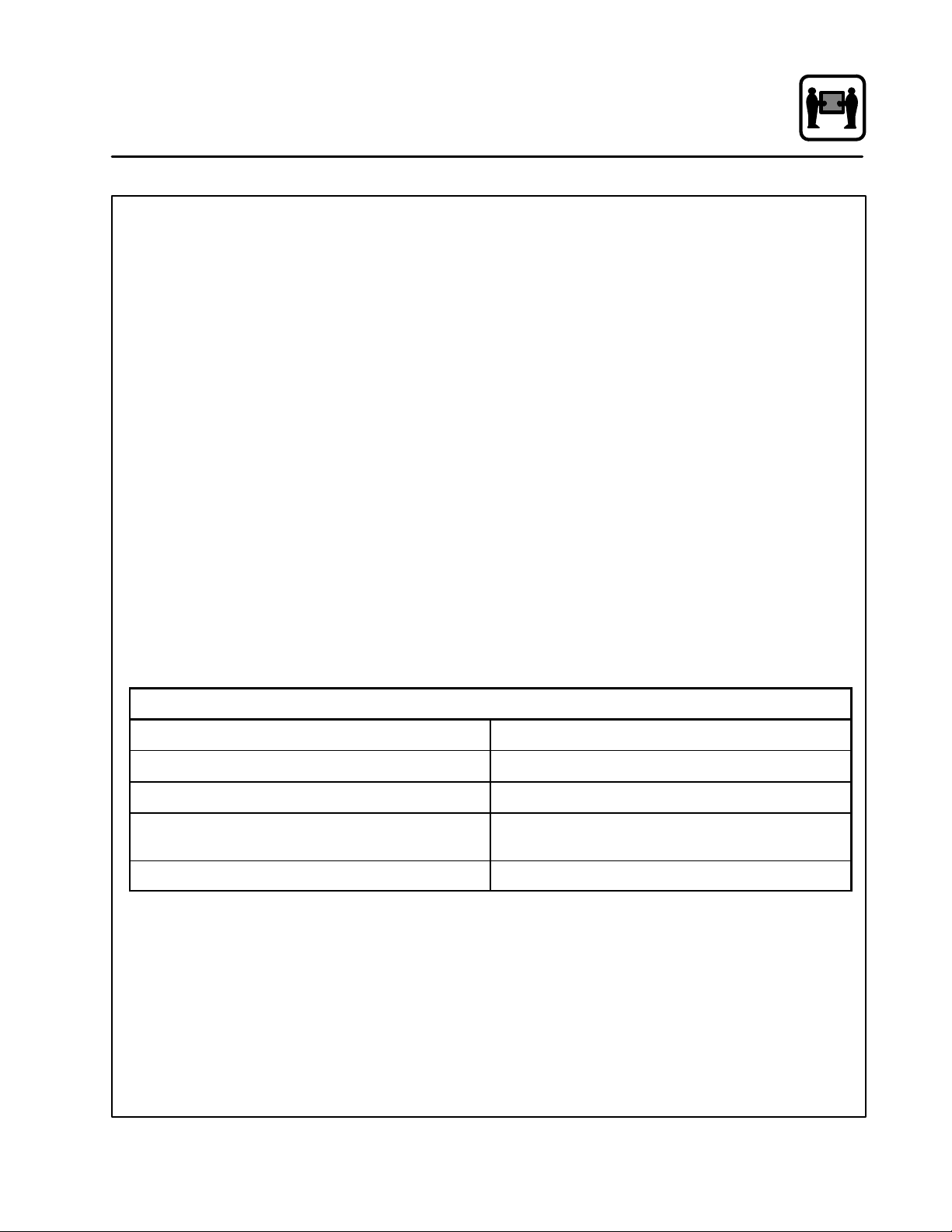
SPECIFICATIONS - COSĆ5HD/AB
Electrical
Specifications 440Ć480 VAC, 3 phase, 44 KW, 58 amps
Water Atmospheric Vented Drain
Water Pressure 40 PSI (276 kPa) minimum
50 PSI (345 kPa) maximum
Water Connection 3/4" NPT Female
3
Page 13
Introduction
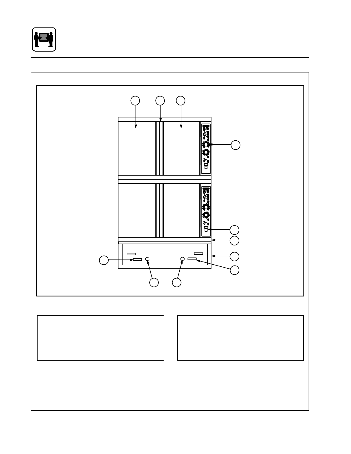
Oven Features
2 23
6
Standard Features
1
7
8
4
1 Control Panel
2 Oven Doors
3 Rotating Door Latch
4 Base Section
5
Figure 1
4
6
5
5 Deliming Port
6 Deliming Handle
7 Optional Meat Probe
8 Door Drip Pan
Page 14
Installation
General Installation Information
The purpose of the installation section of this
manual is to assist the designers and naval archiĆ
tects engineering the installation of a Blodgett
Combi COSĆ5HA Hatchable Combination Oven
into a new or existing ship.
Blodgett Combi has developed the COSĆ5HA to fit
in the same footprint as a Blodgett Mark V convecĆ
tion Oven. The COSĆ5HA Combination oven can
be used as a convection oven, steamer, or in a
Combi" mode in which pulsed steam is comĆ
bined with convection to provide faster cooking
and increase the moisture content of cooked
foods. Because of these features, the oven utilizes
water for generating steam. The Combi is a multiĆ
system cooking oven and is more complex than a
convectional oven. Therefore, more attention has
to be paid to the installation process than that of
a convection oven.
The COSĆ5HA requires the following support sysĆ
tems:
D Power 440 VAC, 3 phase, 60 amp service
D Water Potable, 40 to 50 psi
D Drain Atmospheric vented drain,
1" minimum diameter
D Hood Air venting required for steam
removal
THE INSTALLATION INSTRUCTIONS CONĆ
TAINED HEREIN ARE FOR THE USE OF QUALIĆ
FIED INSTALLATION AND SERVICE PERSONNEL
ONLY. INSTALLATION OR SERVICE BY OTHER
THAN QUALIFIED PERSONNEL MAY RESULT IN
DAMAGE TO THE OVEN AND/OR INJURY TO
THE OPERATOR.
Qualified installation personnel are individuals, a
firm, a corporation, or a company which either in
person or through a representative are engaged
in, and are responsible for:
D The installation of electrical wiring from the elecĆ
tric meter, main control box or service outlet to
the electric appliance.
Qualified installation personnel must be experiĆ
enced in such work, be familiar with all precauĆ
tions required and have complied with all requireĆ
ments of state or local authorities having
jurisdiction.
Reference: National Electrical Code, ANSI/NFPA
70-Latest Edition and/or Canadian Electrical
Code CSA C22.1 as applicable.
This equipment is to be installed in compliance
with the Basic Plumbing Code of the Building OffiĆ
cials and Code Administrators International Inc.
(BOCA) and the Food Service Sanitation Manual of
the Food and Drug Administration (FDA).
Appliance is to be installed with backflow prevenĆ
tion in accordance with applicable federal, provĆ
ince and local codes.
5
Page 15

Installation
Delivery and Location
DELIVERY AND LOCATION
The COSĆ5HA hatchable combination oven is
shipped fully assembled on a special vibration reĆ
sistant pallet. In addition, the oven is mounted on
two hardwood skids to facilitate removal from the
pallet. These skids were designed to match the
height of the separate installation base. This alĆ
lows the assembled oven to be slid directly onto
the base after the installation base is mounted in
position and hard plumbed with potable water and
electric power.
COSĆ5HA dimensions:
Height 62.25" with legs
68.25" with 6" legs
65" with base
Width 38.19"
Depth 44.13"
The following clearances are required for the
COSĆ5HA:
Sides 0"
Rear 6"
UNPACKING
1. Remove the protective cover around the oven.
Inspect the unit for visible damage.
2. Remove the bolts that lock the 2Ć1/2" x 4"
hardwood skids to the pallet base.
3. Use a forklift to raise the oven assembly off the
pallet. The skids can be left in position to assist
in moving an assembled oven onto the instalĆ
lation base or discarded after the oven assemĆ
bly is unbolted into separate components for
passage through hatches.
ASSISTANCE
Blodgett Combi also provides engineering assisĆ
tance when custom installation kits are required.
Our goal is to ensure that each oven installation
can be made in the most efficient and economical
manner.
For further information, please contact the BlodĆ
gett Combi Engineering Department:
D Phone 1Ć800Ć331Ć5842
D Fax 802Ć860Ć3702
6
Page 16
Installation
Installation Base
There are two installation base configurations. If
you do have a base with leg feet, (this configuraĆ
tion is rarely used on board Navy vessels) proceed
to the next page and continue the installation proĆ
cedure.
The Blodgett Combi COSĆ5HA utilizes a stainless
steel locking installation base. The base is availĆ
able with or without legs. The installation base was
designed to facilitate the installation process and
to improve the access to the oven if and when maĆ
jor service is required.
Since the COSĆ5HA is slightly narrower than the
installation base, multiple bases can be installed
side by side on the deck with no allowance for side
clearance.
1. Secure the 2Ć1/2" high installation base using
one of the following methods:
a.) Weld the base directly to the deck.
b.) Bolt the base to the deck.
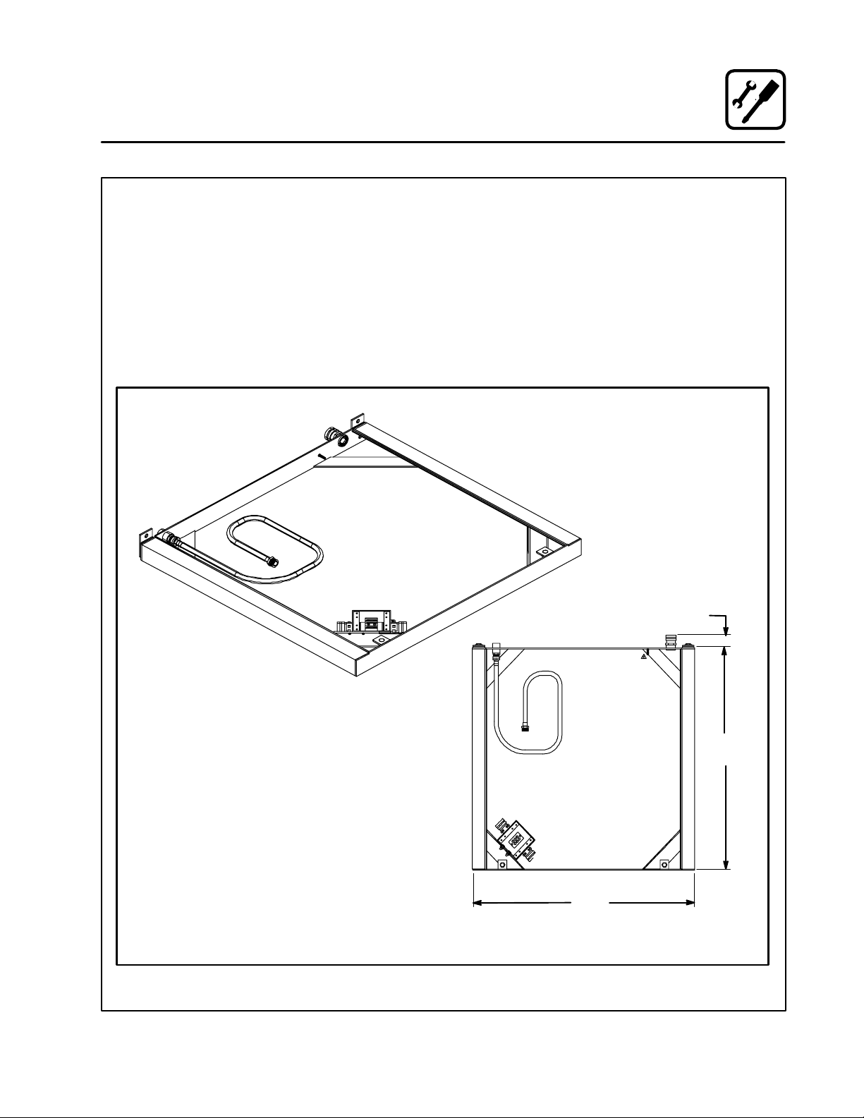
2. Seal the base with an NSF approved sealant.
1.44
INSTALLATION BASE
Figure 2
7
33.91
38.37
Page 17
Installation
Installation Base
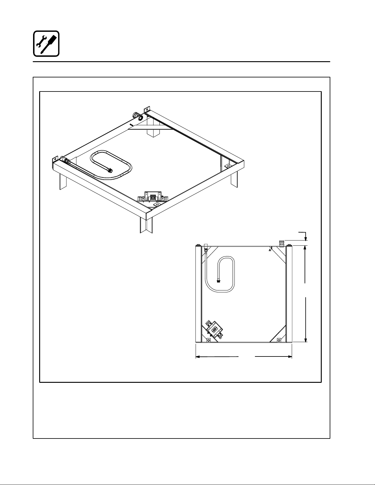
INSTALLATION BASE WITH OPTIONAL LEGS
Figure 3
1.44
33.91
38.37
8
Page 18
Installation
Utility Connections
WATER CONNECTION
The oven requires access to potable water with an
inlet pressure of approximately 40 to 50 PSI.
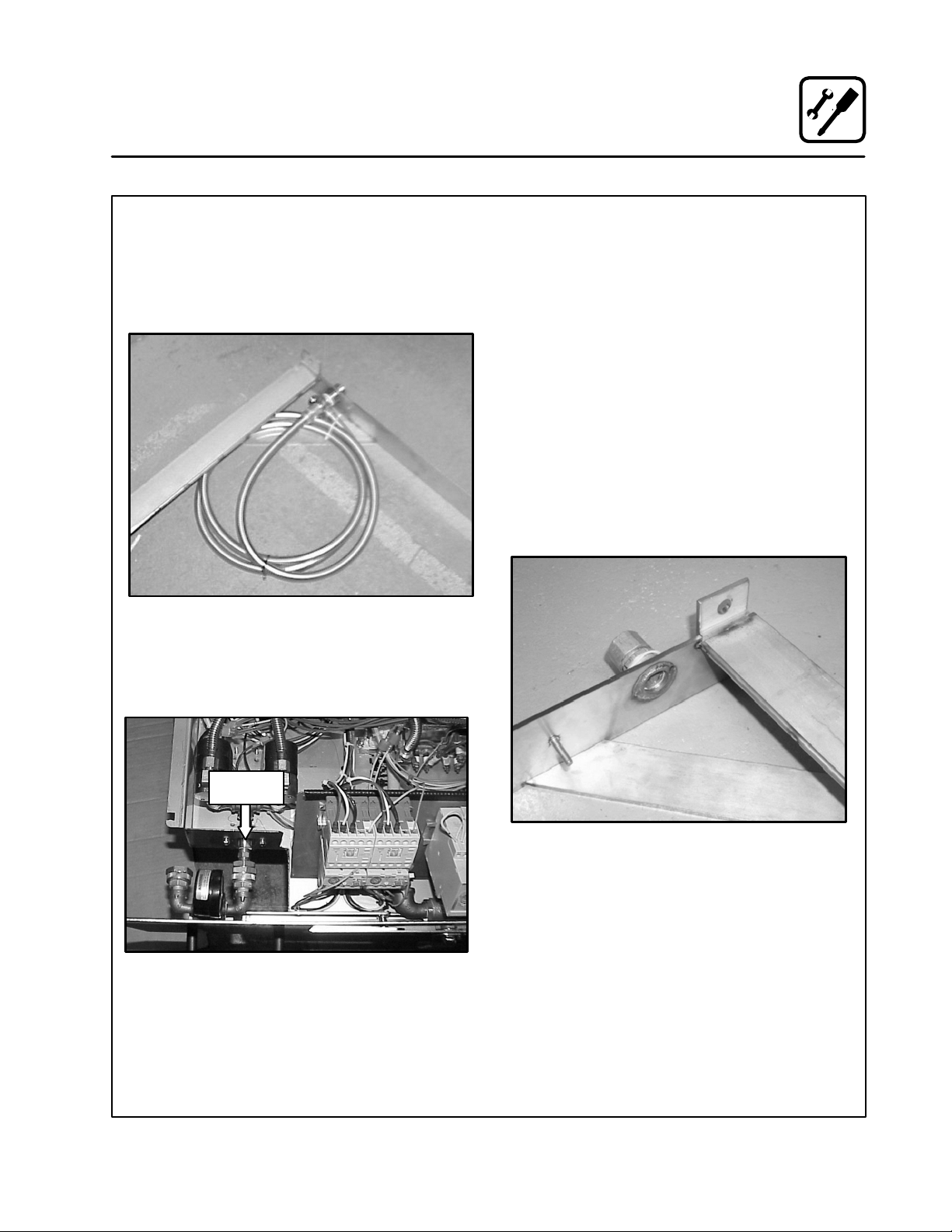
1. The water is connected to the rear of the instalĆ
lation base at the 3/4" NPT female coupling.
Figure 4
2. The water is directed to the oven through an
inĆline pressure regulator and a flexible interĆ
nal hose which connects to a fitting in the front
of the oven. (Set at 35 psi.)
DRAIN CONNECTION
The unit is provided with an optional wrotĆcopper
soldered end tube fitting reducer 3" x 2" funnel that
may be fixed to the installation base. For multiple
oven installations, install a deck mounted sloping
drain with individual funnels positioned to accept
the drain outlets of the individual ovens.
The power requirement of the oven is 440 volt, 3
phase, 60 amp service.
1. The electrical service is brought into the oven
through the seal tight connector located on
the rear of the installation base.
2. The power leads are brought into a water
proof terminal box located in the front of the
installation base.
3. A grounding stud is supplied on the inside of
the installation base. See Figure 6.
Connect
Hose Here
Figure 6
Figure 5
9
Page 19
Installation
Oven Installation - No Dismantling Required
Use this procedure if the oven assembly does not
have to be dismantled to bring it into the galley
where the installation base has been fitted.
1. Slide the oven assembly on the shipping skids
in front of the installation base.
2. Remove the two 1/2" bolts from the front of the
installation base. See Figure 7.
1/2" Bolt
Figure 7
3. Unscrew the front panel from the oven base
section. Leave the hoses connected to the
front panel and the oven base section.
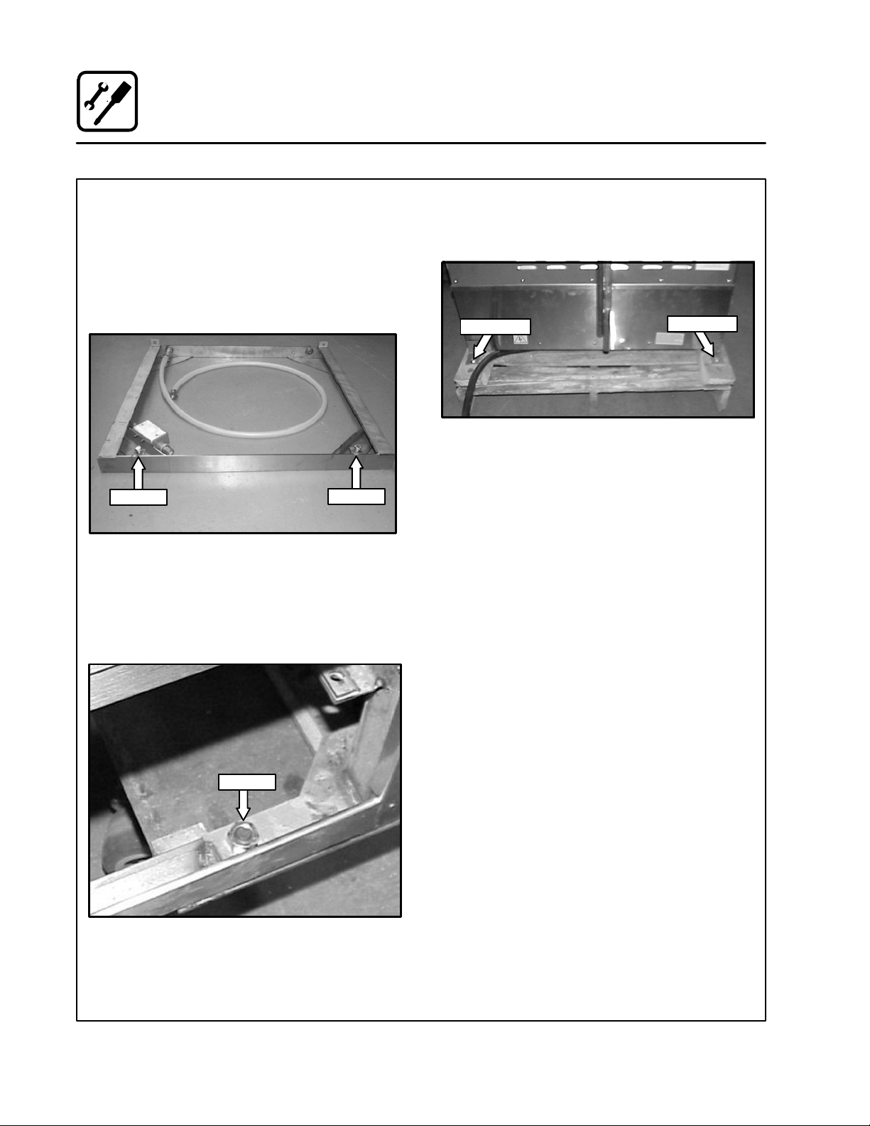
4. Remove the two bolts securing the skids to the
front of the oven base section. See Figure 8.
1/2" Bolt
1/2" Bolt
5. Remove the two bolts and angle plates securing
the skids to the rear of the oven base section.
See Figure 9.
Bolt & Plate
Figure 9
6. Move the oven assembly to the installation
base as follows:
a.) Lubricate the top surface of the installaĆ
tion base with a little grease or silicone
spray.
b.) Slide the oven assembly off the skids onto
the tracks of the installation base.
c.) The locking pins on the rear of the oven
base section will fit into and lock the base
to the upright tabs attached to the installaĆ
tion base.
7. Reinstall the two bolts that were removed in
Step 2, from the installation base through the
oven base section into the installation base.
See Figure 8 for installation location.
8. Hook up water and electrical connections to the
oven base section. Refer to Figure 4 and
Figure 5 on page 9 for water connection locaĆ
tions.
Bolt & Plate
Figure 8
10
Page 20
Installation
Oven Installation - Some Dismantling Required
Use this procedure if the oven assembly will be
dismantled to bring it into the galley where the
installation base has been fitted.
The assembled oven consists of three sections:
D upper oven section
D lower oven section
D oven base section.
The oven base section consists of the major elecĆ
trical components, steam generators, and the atĆ
tachment components for mating the oven asĆ
sembly to the installation base which is mounted
directly to the deck. In order to dismantle the oven
assembly, you will have to separate electrical wire
harnesses and plumbing lines. We recommend
that you tape both sides of each electrical and
hose connection and mark them for easy identifiĆ
cation during reassembly.
If you are installing more than one oven assembly,
keep all hardware and panels associated with one
oven assembly separate from the other oven asĆ
semblies. If the oven assembly has to be disĆ
mantled in order to fit through the hatches, use the
following procedure:
OVEN DISMANTLING
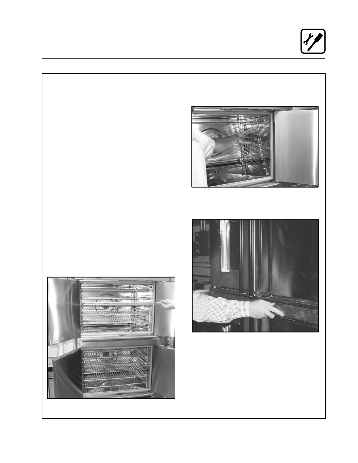
1. Remove the racks from the inside of both the
upper and lower oven sections. See Figure 10.
2. Remove the side support racks from the inĆ
side of both the upper and lower oven secĆ
tions. See Figure 11.
Figure 11
3. Remove the drip pan from the front of both
ovens. See Figure 12.
Figure 10
Figure 12
11
Page 21
Installation
Oven Installation - Some Dismantling Required
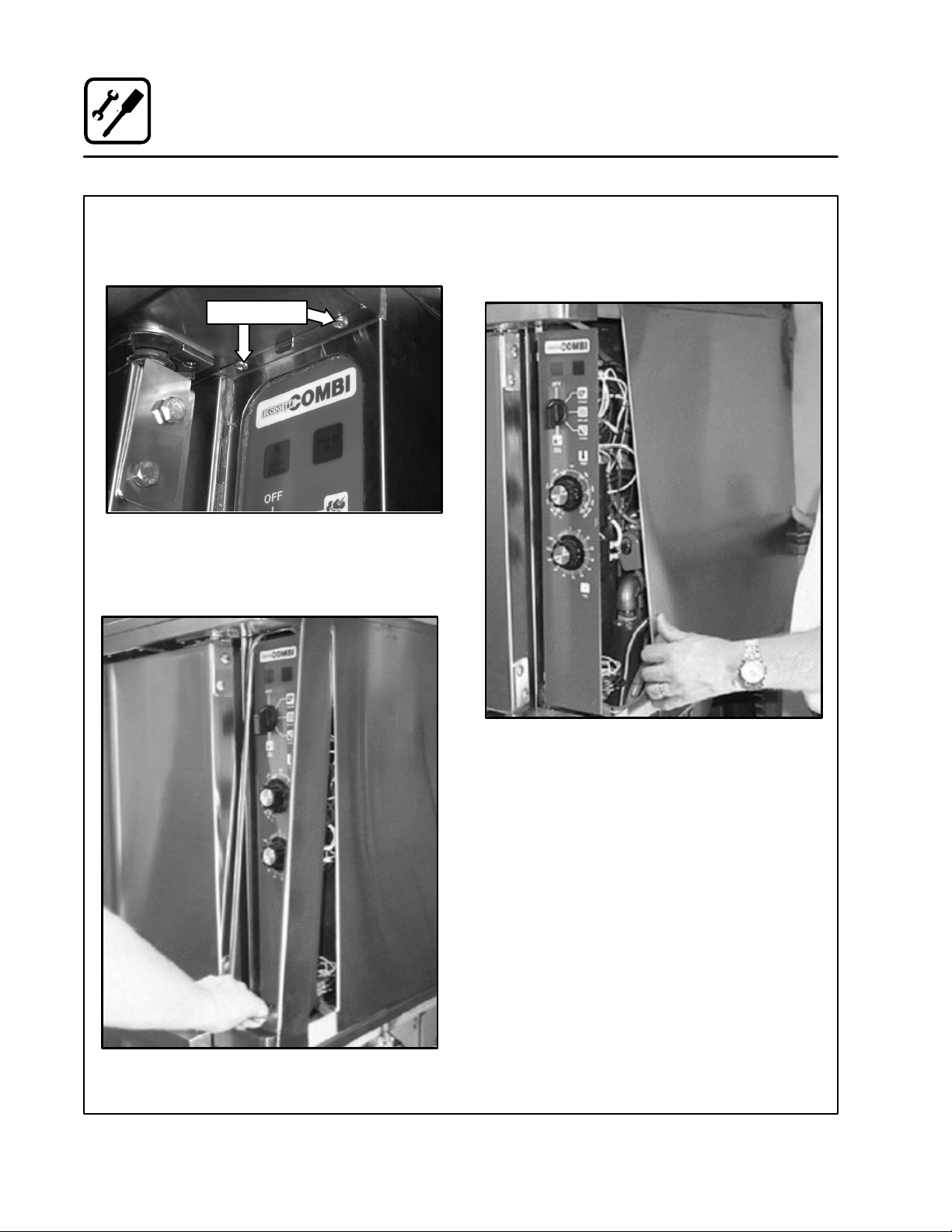
4. Remove the upper and lower screws holding
the control panel cover. See Figure 13. Do this
to both the upper oven and the lower oven.
Mounting Screw
Figure 13
5. Remove the control panel cover by sliding it
forward. The upper and lower side edge must
clear the front trim.
6. Remove the right side rear panel by sliding it forĆ
ward about an inch and then lifting the entire paĆ
nel to free the retaining springs. See Figure 15. Do
this to both the upper oven and the lower oven.
Figure 14
Figure 15
12
Page 22

Oven Installation - Some Dismantling Required
7. On the rear of the COSĆ5HA oven, loosen four
hose clamps so you can remove the copper
drain assembly. Loosen the two clamps closĆ
est to the oven drains and the two clamps conĆ
necting the drains to the top vent assembly.
Remove the drain assembly. See Figure 16.
Hose Clamps
Hose Clamps
Hose Clamps
Installation
Figure 17
Hose Clamps
Figure 16
8. The oven base section has electrical and
plumbing fittings connected to both upper
and lower oven sections. To separate the
three oven sections (base, upper & lower) you
will need to disconnect these fittings. Refer to
Figure 17. Disconnect the large black multiĆ
pin wire connectors in each section.
9. Disconnect the white multiĆpin connectors in
the upper and lower oven sections. See
Figure 17.
10. Disconnect the three hot air electrical wires
from the terminal blocks in both the upper and
lower oven sections. Also remove the three
wires in the small terminal block below the eleĆ
ment wires. (Both sections) See Figure 18.
Figure 18
13
Page 23

Installation
Oven Installation - Some Dismantling Required
11. Disconnect the two wires to the lower fan only.
Remove the rear body panel on the lower oven
section and the rear body panel on the base.
Refer to Figure 19.
Figure 19
12. Refer to Figure 20. Remove the two screws
holding the conduit bracket in place in the botĆ
tom oven section. Slide the bracket out of the
way and reinstall the two screws. This bracket
needs to be loose so the wire harnesses can
be routed out of the upper and lower oven secĆ
tions to separate the three sections.
securing the bracket holding the 90_ brass fitĆ
ting to the frame. See Figure 21. Repeat for
other connector.
NOTE: Silver pipe insulation not shown for
clarity.
14. Remove the three bolts (1/2 inch diameter)
that connect the top and lower oven sections
together.
Two bolts are located in the rear upper left and
right corners of the lower oven section. These
bolts can be accessed from the back of the
lower oven section. See Figure 23.
The third bolt is accessed from the right side
of the lower oven section. It is located in the
upper right hand corner. See Figure 24.
Figure 20
13. To the left of the lower oven drain is a 90_ brass
fitting. Disconnect the upper straight steam
connect fitting with a wrench from both the
90_ brass fittings. Next remove the two bolts
14
Handle
Figure 21
Handle
Figure 22
Page 24

Installation
Oven Installation - Some Dismantling Required
Bolt
Figure 23
15. Remove the upper oven section from on top of
the lower oven section. Use care not to chafe
any of the harnesses that come from the base
section. Use gloves to protect hands from any
sharp edges.
16. Unscrew the front panel from the oven base
section by removing the perimeter screws
only. Slide the tray forward approximately 12"
by pulling on the two U" shaped handles. See
Figure 22. Leave the hoses connected to the
front panel and the oven base section.
17. Remove the four bolts (1/2 inch diameter) that
connect the lower oven section and oven base
section together.
Two bolts are located in the rear upper left and
right corners of the oven base section. These
bolts can be accessed from the back of the
oven base section. See Figure 24 and
Figure 25.
The third bolt is accessed from the right side
of the oven base section. It is located in the upĆ
per front right hand corner. See Figure 26.
The fourth bolt is accessed from the left side
of the oven base section. It is located in the upĆ
per front left hand corner. See Figure 27.
18. Remove the lower oven section from atop the
oven base section. Use care not to chafe any
of the harnesses that come from the base secĆ
tion. Use gloves to protect hands from any
sharp edges.
Figure 24
Figure 25
Figure 26
Figure 27
15
Page 25

Installation
Oven Installation - Some Dismantling Required
OVEN REĆASSEMBLY
After the installation base has been secured in
position, connect the potable water line and elecĆ
trical wires to the base assembly. Insure that all utiĆ
lities are OFF before beginning the reassembly of
the COSĆ5HA oven. The power distribution box loĆ
cated in the base must have a service loop such
that it will reach the main input power terminal
blocks located in the center, rear of the base oven
section.
1. Remove the two 1/2" bolts from the front of the
installation base. See Figure 28.
1/2" Bolt
Figure 28
2. Lubricate the top surface of the installation
base with a little grease or silicone spray. PosiĆ
tion the oven base section onto the flat track
surface of the installation base approximately
4" to 5". Support the front of the oven base
section with a piece of 2" pipe (2Ć3/8" OD
approximately) by 39" (minimum) long.
3. Apply a 1/8 inch bead of clear silicone RTV to
the perimeter of the top edge of the oven base
section. Lift the lower oven section onto the
oven base section. Use gloves to protect
hands from any sharp edges.
1/2" Bolt
4. Install the four bolts (1/2 inch diameter) that
connect the lower oven section and oven base
section together.
Two nuts are located in the rear lower left and
right corners of the lower oven section. These
nuts can be accessed from the back of the oven
base section. See Figure 24 and Figure 25 on
page 15.
The third nut is accessed from the right side of
the oven base section. It is located in the lower
front right hand corner of the lower oven secĆ
tion. See Figure 26 on page 15.
The fourth nut is accessed from the left side of
the oven base section. It is located in the lower
front left hand corner of the lower oven secĆ
tion. See Figure 27 on page 15.
5. Carefully route the wires from the base oven
section into the lower oven section. Resecure
the conduit in place with the two screws. See
Figure 20.
6. Apply a 1/8" bead of clear silicone RTV to the
perimeter of the top edge of the lower oven
section. Lift the upper oven section onto the
lower oven section. Use gloves to protect
hands from any sharp edges.
7. Install the three bolts (1/2 inch diameter) that
connect the top and lower oven sections toĆ
gether.
Two nuts are located in the rear lower left and
right corners of the upper oven section. These
nuts can be accessed from the back of the
lower oven section. See Figure 29.
The third nut is accessed from the right side of
the lower oven section. It is located in the upĆ
per front right hand corner of the upper oven
section. See Figure 30.
16
Page 26

Oven Installation - Some Dismantling Required
Bolt
Bolt
Figure 29
Bolt
Figure 30
8. Refer to Figure 31. To the left and right of the
lower oven drain is a 90Ćdegree brass fitting.
Refit the mounting bracket for the 90Ćdegree
fitting in place and attach the two mounting
bolts which secure it. Reconnect the upper
straight steam connect fittings with a wrench
to both of the 90 degree brass fittings.
Installation
9. Install the rear body panel to the lower oven,
but leave the bottom row of screws off so you
can install the rear body panel to the base secĆ
tion later.
10. Reconnect the electrical wires in the upper
and lower oven sections. Each section has a
large black multiĆpin connector, two large
white connectors, and three element wires. In
the lower oven section reconnect the fan wires
to the cool fan in the rear. Refer to previous FigĆ
ures 16,17, & 18.
11. Install the funnel drain as follows:
a.) Hold the funnel bracket and fasten the
wrap around bracket around the funnel
using the 10Ć24 screws.
b.) Using the 1/4Ć20 screws, fasten the funnel
bracket to the bottom of the install base.
Refer to Figure 32.
12. Review instructions in STEPS 1 thru 11 to enĆ
sure that all connections have been made propĆ
erly, hoses are not kinked, and all electrical wire
harnesses are routed correctly to prevent chafe
or damage.
13. Complete the attached checklist document.
Figure 31
17
Page 27

Installation
Oven Installation - Some Dismantling Required
14. Slide the COSĆ5HA oven until it is about 1'
from locking into the rear of the installation
base. Insure that the potable water line from
the base oven section is connected to the
installation base. Refer to Figure 4 and Figure 5
on page 9 for water connection locations.
Connect the electrical wire service loop to the
base oven section in the center, rear where the
power terminal block is located
15. Slide the oven assembly back onto the installaĆ
tion base. The locking pins on the rear of the oĆ
Funnel
Wrap Around
Bracket
ven base section will fit into and lock the base
to the upright tabs attached to the installation
base. Install the two bolts (1/2 inch diameter) reĆ
moved in STEP 1 (Figure 28), thru the oven
base section and into the installation base.
16. Install the rear panel to the base oven section.
Locate the copper drains. Reinstall the top and
bottom copper drains. Tighten all hose clamps.
See Figure 16 and Figure 32.
INSTALLATION COMPLETE. PROCEED WITH
CHECKĆOUT PROCEDURE.
Wrap Around
Bracket
Figure 32
Funnel
18
Page 28

Oven Installation - Some Dismantling Required
OVEN INSTALLATION CHECKLIST
j Installation base secured
j Potable water connected
j Electrical power connected
j Removed bolts from install base
j Lubricated install base, positioned oven
j Siliconed top edge of oven base
j Installed bolts to oven base and lower oven
j Installed rear body panel
j Siliconed top edge of lower oven
j Installed bolts that connect lower oven to top
oven
Installation
j Installed rear body panel
j Reconnected steam line
j Reconnected electrical wire harnesses
j Installed optional funnel drain, if applicable
j Check for not kinks, no chance of chafing on
harness
j Replaced control panels
j Slide oven back into place
j Hooked water and electrical to base
19
Page 29

Operation
Oven Startup and Shutdown
OVEN STARTĆUP
1. Turn the mode switch to the desired mode,
Steam, Hot Air, Combi, Cool Down.
STEAM MODE
1. Turn the mode switch selector knob to the
Steam Position. The green POWER" indicaĆ
tor lamp illuminates on the front control panel.
2. Steam fills the cavity and is controlled by a
nonĆaccessible internal thermostat.
Preheating for the STEAM mode
Before the first use of the appliance, daily or after
the oven has been idle for 3 hours, preheat with
the STEAM function until steam enters the oven
cavity. The appliance can then be loaded.
HOT AIR MODE
1. Turn the mode selector switch to the Hot Air
position. The green POWER" indicator lamp
illuminates on the front control panel.
2. Set the Hot Air thermostat to the desired temĆ
perature. The Thermostat lamp illuminates inĆ
dicating the cavity temperature is below the
desired set point.
3. When the cavity temperature reaches the deĆ
sired set point, the temperature indicator lamp
goes off.
Preheating for the HOT AIR mode
COMBI MODE
1. Turn the mode selector switch to the Combi
position. The green POWER" indicator lamp
illuminates on the front control panel.
2. Set the Hot Air thermostat to the desired temĆ
perature.
3. The hot air thermostat lamp illuminates, indiĆ
cating the cavity temperature is below the deĆ
sired set point.
4. Once the cavity temperature reaches the deĆ
sired set point, the temperature indicator lamp
goes off.
5. The steam and hot air modes come on to satĆ
isfy the thermostat set points.
Preheating for the COMBI mode
Always preheat the appliance prior to loading.
Open the door and load the product quickly.
COOL DOWN
1. Turn the mode selector switch to the Cool
Down mode.
2. The convection blower comes on with the
door open or closed.
OVEN SHUT DOWN
1. Turn the mode selector switch to the off posiĆ
tion.
Always preheat the appliance prior to loading.
Open the door and load the product quickly.
20
Page 30

Operation
Standard Controls
CONTROLS IDENTIFICATION SEE FIGURE 33
1. DON'T STEAM LIGHT
Indicates the unit is too hot to operate in the
steam mode. Place the unit in the Cool Down
mode until the temperature is below 230_F
(110_C). This light does not inhibit steam proĆ
1
3
4
6
2
5
duction.
2. POWER ON LIGHT
Indicates the unit is in Steam, Hot Air or
Combi.
3. MODE SELECTOR SWITCH
Turns power to the oven on or off. Allows seĆ
lection of Steam, Hot Air, Combi or Cool Down
Modes.
4. TEMPERATURE DIAL
Used to set desired cooking temperature.
5. HEATING INDICATOR LIGHT
Lights when the Hot Air heating is in operation.
6. TIMER DIAL
Used to set desired cooking time.
7. FAN SPEED SWITCH
Used to select low or high speed.
NOTE: When looking through the door the blower
rotation must be clockwise.
7
Figure 33
21
Page 31

Operation
Standard Controls
OPERATION
1. Turn the MODE SELECTOR Switch (3) to the
desired function.
The POWER ON Light (2) illuminates.
2. Set the TIMER (6) for the desired cooking time
or set it to STAY ON. The buzzer sound and the
unit shuts off when the time has expired.
3. For the HOT AIR and COMBI modes, set the
TEMPERATURE Dial (4) to the desired cook
temperature. The HEATING INDICATOR Light
(5) illuminates and stays lit until the desired
temperature is reaches.
4. The selected mode operates automatically.
The temperature, time and mode can be alĆ
tered at any time during the cooking process.
The operation can be stopped by the use of
the Mode Selector Switch or by opening the
door.
5. At the end of the specified time period, the
buzzer sounds and the appliance will shut off
automatically. Move the TIMER (6) to the STAY
ON position to stop the buzzer and restart the
unit.
6. To cool down the oven cavity, switch the
MODE SELECTOR Switch (3) to COOL
DOWN. In the Cool Down mode neither the
temperature dial or the timer will be operationĆ
al. The blower will function with the door open
or closed.
7. The mode selector switch is also the main
power switch. In the OFF position the apĆ
pliance is not operational.
NOTE: Always disconnect the power supply beĆ
fore servicing the unit.
22
Page 32

Operation
Optional Meat Probe
CONTROLS IDENTIFICATION SEE FIGURE 34
1. MEAT PROBE SWITCH
Controls power to the meat probe.
2. MEAT PROBE CONTROL
Use to set the desired probe temperature. InĆ
dicates the actual temperature of the product
3. MEAT PROBE CONNECTOR
Receptacle for the plug in meat probe.
NOTE: For sanitation it is recommended that
the meat probe remain plugged into
the front panel receptacle at all times.
OPERATION
Measuring the product core temperatures during
long roasting periods is very practical. It is espeĆ
cially important for products such as Roast Beef to
reach a specific internal temperature.
Place the probe through to the middle of the prodĆ
uct's thickest section. Be sure the probe does not
touch any bone and the tip is not in a fat pocket.
These conditions can cause inaccurate readings.
1. Set the MODE SELECTOR Switch to the deĆ
sired function.
2. Turn the MEAT PROBE Switch (1) to ON.
3. To set the desired core temperature press the
blue SET BUTTON (4) on the MEAT PROBE
CONTROL (2).
Use the up arrow key (6) to increase the setĆ
point temperature. Use the down arrow key
(5) to decrease the setpoint temperature.
Press the set button again to store the setĆ
point.
4. Set the TIMER to STAY ON. The cooking proĆ
cess runs automatically.
When the selected core temperature is reached,
the buzzer will sound and the appliance shuts off
automatically.
The temperature and mode can be changed
at any time during the process.
5. Shut the appliance off by setting all switches
to OFF.
NOTE: When setting the internal temperature, be
sure to allow for carryĆover cooking after
the roast is removed from the oven
1
2
3
Figure 34
23
WATLOW
1
2
RDY
SET
4 5 6
Page 33

Cooking Guide
The Hot Air Mode
INFORMATION ABOUT THE HOT AIR MODE
How cooking with hot air works
Hot air is circulated at high speed on all sides of
the product, providing a concentrated cooking
process. This function is extremely effective for inĆ
tensive browning.
What can be cooked with hot air
Hot air can be used for all foods which need a short
cooking time and intensive ābrowning. For examĆ
ple: steaks, cutlets, fillets, breaded foods, and varĆ
ious baked foods. This function may also be used
for au gratin.
COOKING WITH THE HOT AIR MODE
Temperatures
For intensive browning and crispy crusts, preheat
the oven to the maximum temperature of
500_F/260_C. This is especially important when
searing.
Performance
The charts showing performance examples (See
Cooking Guide) are based on full capacity. Better
results may be obtained by reducing product
quantities.
Cooking Times
Due to the constant hot air circulation, this apĆ
pliance cooks faster than conventional grills and
deck ovens.
Cooking times will vary according to the quality,
weight, and height of the product.
Trays or Racks?
This is a question of individual choice. Racks have
the advantage of browning food on all sides; the
underside of tightly packed foods may be lighter
when using trays.
TIPS AND PROCEDURES
Loading the Oven
Place like sized product together on one rack. āāIn
order to ensure proper air circulation, racks āand
ātrays āshould ānot āābe āācrowded.
Oiling
The quality of some foods, such as steaks and
breaded meats, can be enhanced by coating with
oil or a paprika oil mixture.
Breaded Foods
The degree of browning is dependent on the
amount of raw material in the breading. Oil can be
used to intensify the browning. Press the breading
firmly but don't overload the oven. Flouring seared
foods is not recommended.
Baking
For baking, the Mode selector switch may be set
to HOT AIR, STEAM, COMBI or any combination
according to the type of product. Steam added to
the baking process opens up a wide range of posĆ
sibilities: such as hard crusts and good shine on
certain types of breads. Here are some tips for
baking:
D Preheat oven to the baking temperature.
D Baking ātemperatures ācan āgenerally āābe set
50Ć75_F/20Ć25_C lower than with a conventionĆ
al baking or roasting oven. When in doubt, lowĆ
er the temperature.
D Theā bakingā timeā canā be āshorterā than āwith conĆ
ventional methods.
D Slightly reduce your quantities of mixtures with
excessive moisture.
D Use ādeep trays for light mixtures in order to enĆ
sure undisturbed baking. Baking forms should
not be higher than 3 inches.
D Cakeā āāformsā ā(āpans, āāātins,ā āāetc.), āāāshould be placed
on racks.
D Distributeāā foods āāevenly āwhenā āloading half loads.
D Use āevery āsecond ātierā for baking bread,ā heavyāā
mixtures (yeast doughs, etc.) and well filled
forms.
24
Page 34

INFORMATION ABOUT THE STEAM MODE
How steaming works
This mode gently cooks food using nonĆpressurĆ
ized steam. Fresh steam is directed into the oven
from the generator. It is not necessary to add water
to foods during the cooking process.
What can be steamed
Vegetables, side dishes, fish, meat, poultry, diet
foods, garnishes, dumplings, casseroles, meat
loaf, fruits, desserts and eggs.
How to operate the Steam mode
Simply turn the Mode Selector Switch to the
STEAM position and set the Timer.
The advantages of steaming
Steaming āis āa wellĆknown cooking process freĆ
quently used in restaurant and institutional kitchĆ
ens. With this appliance it is now possible to enjoy
the many advantages of steaming, some of which
are:
D Shorter Cooking Times
The continuous processing of large amounts of
product is no problem and long cooking times
are no longer necessary. Even with full loads,
relatively shorter cooking time for food is needĆ
ed.
Cooking Guide
The Steam Mode
D High Quality Foods
With ātheā useāāāofā steam,ā valuable taste and aroma
are preserved since steamed foods retain their
own natural taste. During the steaming process
foods retain the nutrients and vitamins which
are lost in water during boiling. Therefore, when
compared, steamed foods have much āābetter
color than foods that have been boiled. āAlso,ā by
using shallow containers the product is not layĆ
ered as deeply and mushing is avoided.
D Vitamin Retention
Vitamins are not destroyed. This is due to the
shorter cooking times, the use of less or little
water and the use of a low temperature; slightly
less than 212_F/100_C.
D Firmness
With the use of steam, overcooking āisā notā a
problem and firmness can be individually conĆ
trolled.
D Simultaneously Steaming Different Foods
There is no flavor transfer when cookingā āwithā ātheā
āSTEAM āāmode. For this reason, various types of
food with different cooking times can be loaded
or removed at any point during the cooking proĆ
cess.
25
Page 35

Cooking Guide
The Steam Mode
TIPS AND PROCEDURES
Containers
Both solid and perforated steam table pans of vaĆ
rying sizes (full, half, and oneĆthird size) may be
used in the appliance. Small pans may be placed
on wire racks.
Stocks for Sauces
When trays are used for cooking there is usually
enough stock collected for making sauces. When
using perforated pans, insert a solid pan in the botĆ
tom rack to collect the stock.
Seasoning
Since there is no liquid added during the steaming
process, season using one of the following methĆ
ods:
D Season before cooking: Sprinkle the spice
mixture evenly over the food prior to cooking.
D Oil seasoning after cooking: Stir the oil mixĆ
ture into the product. Steam again for two minĆ
utes in some cases.
Blanching and Prep Work
Large amounts of product can be blanched in a
short amount of time. Trays should not be filled
higher than 3 inches.
The STEAM mode is excellent for preparing vegeĆ
tables for peeling.
Canning and Preserving
The diameter of the containers must not exceed
4Ć5 inches when canning.
Thawing
Thawing time is much shorter when using steam
and produces higher quality food.
Reheating
The use of steam creates an even distribution of
heat, which gives food better taste and retention
of nutrients.
Foods are reheated in the trays in which they were
cooked. Reheating times vary according to the
height and content of the containers.
SAMPLE DISHES
Vegetables
Fresh and frozen vegetables may be steamed toĆ
gether. Frozen vegetables should be loosely scatĆ
tered on the trays. Perforated trays shorten cookĆ
ing time, although solid trays may be used.
Cooking times will vary depending on the quality
of the vegetables. When āsteaming āfresh āvegetaĆ
bles, āācheck the product 3/4 of the way through the
āācooking āāperiod.
Steamed vegetables tend to soften after cooking.
āāāSinceāāāthereāāāāisāāāāaāāāādelay between cooking and serving,
it is best not to steam āvegetables too āsoft.ā Thisā āis
āāespecially important for foods prepared for transĆ
port.
Rice and Potatoes
Rice requires the addition of water for steaming.
Remember that the rice continues to swell after
cooking; plan your quantities accordingly.
Always cook potatoes in perforated pans. Steam
can permeate the potatoes better if they are quarĆ
tered through the width and not the length.
Eggs
Eggs are inserted onto wire racks, either in the
cardboard container or placed into perforated
trays (there is no need to puncture them). Cooking
eggs with the STEAM function saves work and reĆ
sults in less waste since steamed eggs do not
break. Also, the degree of hardness ācan ābe āconĆ
trolled āexactly. Begin timing when the oven winĆ
dow is misted over.
Fish
Fish ācan ābe steamed āin āātrays āāwithout using extra
stock. Use a 1 inch pan for fresh fish (Fillets). For
larger or frozen pieces, use a 2 inch pan.
Poached fish can be prepared with aromatic herbs
āand āvegetables āin āeither āsolid āor perforated pans.
Steam without stock.
Shell fish can be steamed in perforated pans. Use
a solid pan to catch drippings for stock.
26
Page 36

Cooking Guide
The Combi Mode (Steam and Hot Air)
INFORMATION ABOUT THE COMBI (STEAM
AND HOT AIR) MODE
How Combi Mode Works
With this function, the advantages of steam (short
cooking time, less shrinkage) and hot air (intenĆ
sive aroma, appetizing color) are combined.
Steam and hot air circulate at high speeds, āenvelĆ
oping āthe product āon all sides and providing an inĆ
tensive cooking process.
What can be cooked in Combi mode?
All types of roasts, duckling, pork, beef, lamb,
meat loaf, ground chuck foods, casseroles, poulĆ
try, āstuffed vegetables, vegetables au gratin and
yeast doughs.
The advantages of Combi mode?
D Productivity
Previously, several different appliances, and
multiple procedures, were necessary to comĆ
bine āāāheat andāāāsteam preparation. Now all of
these āmethods āācan āābe āāused āāwithout ātime wastĆ
ing interruptions, with one appliance.
D Less Shrinkage
The āāāusual āāāweight āāāloss āāāduring āāāāroasting āāāāin conĆ
ventional appliances can be reduced by apĆ
proximatelyā ā13%āāā āofāāā ātheāā āāoriginalāā weight.
D Juiciness and Crunchy Crusts
When used at the beginning of the cooking proĆ
cedure, the searing action of steam instantly
closes āall āpores. āThis āreduces āāthe āloss of protein
āand āmeat ājuices. Therefore, products with long
roasting times remain juicy. Foods retain their
moisture and roasts develop a āpleasing ācolor āas
āwell āāas āāan āāappetizing crust. āMeats āāhave āāa proĆ
nounced āroasted taste and āāburning āāof āāthe āāsurĆ
face āis āāalmost impossible.
COOKING IN THE COMBI MODE
The COMBI function can be used for āthe āentire
cooking process or for any portion of the cooking
procedure you desire.
What do CombiĆroasting, CombiĆsteaming and
CombiĆbaking mean?
We have created these names since both modes,
STEAM and HOT AIR, can be applied in any comĆ
bination as follows:
D Together, as in the COMBI function.
D In sequence
Example: first STEAM and then HOT AIR.
D Or in sequence and then in combination
Example: first HOT AIR and then COMBI
Or conversely: first COMBI and then HOT AIR.
D Or all three functions in sequence
Example: first STEAM, then HOT AIR, then
COMBI.
For additional tips on when to use each of these
Combi Modes see the Summary of Functions" on
the following page.
27
Page 37

Cooking Guide
Summary of Functions
MODE SELECTION COOKING METHODS PRODUCTS
Steam
Hot Air
Combi
Steam Hot Air
Hot Air Combi
Steaming, defrosting, thawing, reĆ
heatingĆreconstituting, blanching,
preserving, poaching, simmering,
braising, stewing.
Roasting, grilling, baking,
au gratin.
CombiĆsteaming, CombiĆroasting,
CombiĆbaking, defrostingĆthawing,
reheatingĆreconstituting.
CombiĆsteaming,
CombiĆbraising,
CombiĆroasting,
CombiĆbaking,
(Begin with steam, then with dry heat
for crusting, browning, gratinating.)
CombiĆsteaming,
CombiĆroasting, CombiĆbaking,
(Start with dry heat, switch over to
Combi for slow but gentle even
browning, switch back and forth as
necessary.)
Convenience food, potatoes, rice,
fresh or frozen vegetables, fresh or
frozen fish, poultry, meat, fruit, eggs,
puddings, casseroles.
Roast beef, pork, veal, lamb, chickĆ
en, hamburger, fish, stuffed vegetaĆ
bles, toast, lasagne, potatoes, pies,
shortbread, puff pastry, Danish and
French pastry, bread.
Prime rib, whole bone ham, goose,
turkey, fish, mutton, beef, pork roast,
French pastry, bread, rolls, puff
pastry, Danish pastry, convenience
food.
Stuffed peppers, gratinated vegetaĆ
bles, fennel, broccoli, cauliflower,
rack of lamb, pork
French pastry, puff pastry, yeast
dough, turkey, duck, goose, lamb,
stuffed vegetables.
Combi Hot Air
Steam Hot Air Combi
CombiĆbraising,
CombiĆroasting,
CombiĆbaking,
(Start with Combi, finish with dry heat
for crusty, crisp, brown surface,
switch back and forth as necessary.)
CombiĆsteaming,
CombiĆroasting, CombiĆbaking,
(For meats: sear pores closed with
steam, then brown with dry heat, then
switch between Combi and dry heat.
For stuffed vegetables: steam first
and switch between dry heat and
Combi during the rest of the cooking
process.)
28
Whole bone ham, ham in bread
dough (English Ham), whole fillets of
beef, pastry dough, yeast dough
(bread, rolls).
Veal, pork, beef, leg of lamb, goose,
duck, turkey, prime rib, puddings,
stuffed peppers; ideal for all prodĆ
ucts which need a humid cooking
process.
Page 38

Cooking Guide
General Tips and Procedures
USING RACKS
Use racks for roasts needing a longer roasting
time, large roasts (pork, veal, beef, venison,
lamb), searing, toast, au gratin, (chicken, duck,
goose, legs, chops), cooking in containers, thawĆ
ing, baking in tins, etc. When cooking in racks it is
important to turn food products.
USING PANS
D 1I Deep Steam Table Pan
For fried potatoes, hamburgers, au gratin, thawĆ
ing, meat loaf, meat balls, fried, poached and
steamed fish, baked goods, vegetable casseĆ
roles, duck and goose.
D 2I Deep Steam Table Pan
For ācabbage ārolls, āstuffed āpeppers, āstews, ārice,
āvegetables, āsauerkraut, āassorted āfruits āand
ācompote. āAlso āfor ācollecting āāstock, preparing
sauces, etc.
D 2½IDeep Perforated Steam Table Pan
For vegetables without stock, side dishes
(breads) and products with shorter cooking
times.
D 4IDeep Perforated Steam Table Pan
For vegetables (blanching spinach for examĆ
ple), potatoes, shelled or unshelled eggs.
D 6IDeep Perforated Steam Table Pan
For potatoes.
LOADING THE OVEN
To ensure that the product will brown on all sides,
do not āplace āfoods ātoo āclose togetherā. Place the
grain of meats parallel to the air stream ā(left āāto
āāright). āāThis āāensures āābetter āabsorption and shortĆ
ens the cooking process. Place like sized pieces
together on the same rack, smaller pieces cook
more quickly.
Place the food in the appropriate pans/trays or disĆ
tribute it on the racks. Insert racks and trays into
the pan rack. It is recommended that the pan rack
be loaded outside of the oven when processing
large amounts of product. The pan rack for table
models āis āwell āsuited āfor this purpose; it allows āfor
a higher hourly production and an efficient work
sequence.
REMOVING THE PRODUCT
Turn the Mode Selector Switch to OFF before
opening the appliance door.
NOTE: Open the door slowly after steaming! Hot
Steam Will Be Present!
COOKING TIMES
The length of the cooking process depends on the
quality, weight and thickness of the food product.
TEMPERATURES
Typically, the longer the cooking process, the lowĆ
er the temperature.
29
Page 39

Cooking Guide
Suggested Times and Temperatures
PRODUCT SUGGESTED CORE TEMPERATURE
Beef
Fillet of Beef
Roast Beef
Pot Roast
Veal
Saddle of Veal
Loin
Shoulder
Stuffed or Boned
Leg, TopĆside
Pork
Leg
Picnic Shoulder
Ham
Smoked Pork Chops
Ribs
Tongue
medium rare
medium rare
well done
medium
well done
well done
fricandeau
well done
well done
juicy
well done
well done
130_Ć140_F
130_Ć140_F
170_F
160_F
165_Ć175_F
165_Ć175_F
165_Ć170_F
172_F
185_F
185_F
155_F
158_F
150_F
195_F
54_Ć60_C
54_Ć60_C
78_C
70_C
75_Ć80_C
75_Ć80_C
75_Ć78_C
78_C
85_C
85_Ć80_C
68_C
70_C
70_C
90_C
Poultry
Chicken
Goose
Turkey, Duck
Lamb
When the meat is well done it has a core temperature between 173_Ć185_F (79_Ć85_C). The core has
a slightly pink color and the juices are clear.
Saddle
Saddle
Leg
Leg
Pâtés
Pâté 160_Ć165_F72_Ć74_C
NOTE: Actual temperatures may vary from those shown. Write in your proven temperatures for ready refĆ
erence.
well done
well done
well done
slightly pink
well done
slightly pink
well done
185_F
195_Ć198_F
175_Ć185_F
158_Ć165_F
175_F
165_Ć170_F
180_Ć185_F
85_C
90_Ć92_C
80_Ć85_C
70_Ć75_C
80_C
75_Ć78_C
82_Ć85_C
30
Page 40

Cooking Guide
Notes
31
Page 41

Maintenance
Cleaning and Preventive Maintenance
CLEANING THE INTERIOR
Daily cleaning of the appliance is essential for sanĆ
itation, and to ensure against operational difficulĆ
ties.
For difficult cleaning, allow the sprayĆon oven
cleaner to work longer before rinsing.
1. Cool āāthe āoven down to 140_F/60_C or, if the
āāovenāā has āābeenā āidle, āāturnā the steam modeā onā
foār 3 āto ā4ā minutesā inā order āāāto warm the oven
surfaces.
2. Spray āāthe āinteriorā of āātheāā ovenā with a cleaning
solution.
NOTE: Never spray water into the unit when
the temperature is above 212_F. NEVĆ
ER SPRAY WATER IN THE UNIT AFTER
USING THE HOT AIR OR COMBI
MODES.
3. Let āthe ācleanerā āworkāā for āā10ā toā 20 minutes withāāāāā
the āāāāovenā āāāāoff.āāā āForā āādifficult, baked on grease,
etc. allow to work over night.
4. Set the timer for 15 to 20 minutes.
5. Set āātheā āmodeā āāselector switch to Steam. This
will soften all burned on residue.
6. Rinseāā āātheāāā āovenāāāāā interiorā āāāwithāāāāā waterāā (a hose mayāā
ābeāā āused,āā ābut āāātakeāā careā thatā only āātheā āoven'sā inĆ
terior cavity is sprayed with water).
7. Setā āāātheā āāāmode āāāselectorāāā toā āāsteam āāāforā anotherā five
minutes to flush out the oven interior and reĆ
move all detergent residue.
NOTE: The āoven ācavity ā should ā never ā be scoured
or scraped.
On stainless interiors, deposits of baked on splatĆ
ter, oil, grease or light discoloration āmay ābe āreĆ
moved āwith āa good non toxic industrial stainless
steel cleaner. Apply cleaners when the oven is
cold and always rub with the grain of the metal.
The racks, rack supports and the blower wheel
may be cleaned in the oven or by removing them
from the āoven āand āsoaking āthem in a solution of
ammonia and water.
NOTE: DO NOT use corrosive cleaners on the
Oven/Steamer.
CLEANING THE EXTERIOR
Oven exteriors may be cleaned and kept in good
condition with a light oil. Saturate a cloth and wipe
the oven when it is cold; wipe dry with a clean
cloth.
WARNING!!
DO NOT spray the outside of the apĆ
pliance with water.
PREVENTIVE MAINTENANCE
The best preventive maintenance measures are
āāāthe āāāproper āāinitial āāinstallation āāof āāthe equipment and
a program for cleaning the oven routinely. The
Oven/Steamer requires no lubrication. Contact
the factory, the factory representative or a local
Blodgett Combi service company to perform
maintenence and repairs should they be required.
WARNING!!
Disconnect appliance from power supply
before servicing or cleaning.
32
Page 42

Maintenance
Decalcification
The COSĆ5HA has a separate boiler for each unit.
There are deliming ports and handles for each boiler
located on the base unit. The left deliming port and
handle is for the bottom unit. The right deliming port
and handle is for the top oven. To save time the boilĆ
ers should be delimed simultaneously.
The COSĆ5HA should be delimed on a monthly baĆ
sis regardless of water quality or usage. Use the
following procedure to delime the boilers.
WARNING!!
ALWAYS USE PROPER SAFETY EQUIPĆ
MENT WHEN DELIMING. Gloves and eye
safety equipment are recommended.
1. Set both mode selector switches to Steam
mode. Wait until steam is produced. This will
ensure that the water in the steam generators
is hot.
2. Turn the mode selector switches to OFF.
3. Remove both deliming port covers on the
base unit.
4. Add 10 ounces of deliming solution to the deĆ
liming bottle and then add 1Ć3/4 gallons of
warm water.
NOTE: LimeĆaĆwayt or a generic equivalent
are recommended. The main active
ingredient should be a deluted conĆ
centration of phospheric acid.
5. Delime the boilers as follows:
a.) Connect the deliming hose to one of the
deliming ports on the base section.
b.) Turn the corresponding red deliming hanĆ
dle on the base unit so it is vertical. This
opens the deliming port.
c.) Pump in all of the solution.
d.) Close the deliming handle and remove
the deliming hose from the deliming port.
The handle is now horizontal.
6. Repeat STEPS 4 and 5 for the other oven.
7. Allow the ovens to sit with the deliming soluĆ
tion in them for at least 1/2 hour.
NOTE: For heavy lime build up, allow to stand
for 1 hour.
8. Drain and flush the boilers as follows:
a.) Connect a drain hose to one of the delimĆ
ing ports. Allow the boiler to drain comĆ
pletely. The drain hose is not supplied.
b.) Carefully rinse out the deliming container
and fill it with 1Ć3/4+ gallons of fresh water
only.
c.) Turn the oven to Steam and allow the boilĆ
er to fill. Wait at least 2 minutes.
d.) Connect the deliming pump to the same
deliming port on the base section.
e.) Turn the red deliming handle on the base
unit so it is vertical. This opens the delimĆ
ing port.
f.) Pump in all of the water in the deliming
pump.
g.) Close the deliming handle and remove
the deliming hose from the deliming port.
The handle is horizontal.
h.) Connect the drain hose to the same deĆ
liming port on the base section.
i.) Turn the red deliming handle on the base
unit so it is vertical. This opens the delimĆ
ing port.
j.) Let all the water drain from the boiler.
k.) Remove the drain hose and turn the hanĆ
dle to the horizontal position.
9. Repeat STEPS b. and 8 for the other boiler.
10. Reattatch the covers to the deliming ports.
Deliming
Deliming
Port
Port
33
Figure 35
Page 43

Maintenance
Troubleshooting Top Oven Section
HOW TO USE THIS TROUBLESHOOTING GUIDE
Always troubleshoot the circuit in the following sequence. Troubleshoot each oven section this way. Go
from: 1) COOL DOWN 2) HOT AIR 3) STEAM 4) COMBI
If the oven shorts or trips the redundant contactor when selecting the mode switch to the COOL DOWN
position, shut off the main breaker, turn the mode selector switch to COOL DOWN and then turn the main
breaker back on.
COOL DOWN MODE
POSSIBLE CAUSE(S) SUGGESTED REMEDY
SYMPTOM: Motor doesn't run in cool down.
NOTE: The COSĆ5H has a redundant contactor (K1 & K6) which are in series with the 440V operating
components (hot air & steam elements, motors). If a redundant contactor is tripped, the conĆ
trol circuit lights will work (green OVEN ON (H6) and hot air (H5) but the motors and elements
will not work until the fault is determined and the redundant contactor is reset.
S Main circuit breaker is OFF
S StepĆdown transformer (T1) is defective
S Mode selector switch (S1) is not closing beĆ
tween terminals 23 & 24
S Motor contactor K8 is not closing
S The motor overload (OL6) has tripped.
S The circuit overload (K6) has tripped.
S Verify the main breaker is not tagged out or the
breaker has tripped. If the main breaker is tripped,
there is a high probability of a steam or hot air eleĆ
ment short. Proceed to the appropriate trouble
shooting section and review. Overload has tripped.
Isolate which oven section is tripping the breaker.
S Verify 440V input to the transformer. Check the
transformer coils. Approximately 2.2 ohms priĆ
mary / .7 ohms secondary. Output is 220VAC.
Replace if needed.
S Verify switch is closing with meter. Replace if
needed.
S The contactor coil resistance is approximately
1.39K ohms. Verify voltage between the coil A1
and A2.
S Check windings of motor. Resistance of windĆ
ings is approximately 85 ohms. Running current
is .5 plus amps. To reset the overload, lift the
plastic cover and push in test reset. Verify the
overload setting, .63. Review Convection Motor
runs Intermittently" before replacing.
S See following circuit description
34
Page 44

Maintenance
Troubleshooting Top Oven Section
Each oven section has a redundant contactor that
will not allow the high voltage controls to work (hot
air elements, steam elements, & convection moĆ
tors) should a fault be detected. Review the followĆ
ing fault probable causes. If you reset a fault, you
must determine the route cause of the overload.
When the circuit overload trips, it breaks all 3 inĆ
coming legs to the hot air elements, steam eleĆ
ments, and motor. It also has an auxiliary contact
which breaks the return leg to the contactor coils
in the low voltage control circuit to these associatĆ
ed components.
1. The steam generator high limit (TAS1) has
tripped. Proceed to Steam Mode" to deterĆ
mine cause.
2. The motor overload (OL6) has tripped. Review
motor overload has tripped in Cool Down".
POSSIBLE CAUSE(S) SUGGESTED REMEDY
SYMPTOM: Convection motor runs intermittently.
S Thermal overload on motor (M1) is opening and
closing (automatically resets when cooled).
3. The steam overload (OL2) has tripped. ProĆ
ceed to Steam Mode" to determine cause.
4. The hot air overload (OL4) has tripped. ProĆ
ceed to Hot Air Mode" to determine cause.
NOTE: Overloads have an LED on them which
flashes when an overload is tripped.
5. Two consecutive flashes - indicates a current
overload / probable element short
6. continuously ON" - indicates a phase fault:
high / low / missing one or more legs
7. On / Off continuous flash - the overloads are
smart" and will recognize if all the high voltĆ
age legs are not wired in phase. This can hapĆ
pen on initial start up if a leg is reversed (moĆ
tors running backwards (clockwise) or a
componant has been changed and not wired
exactly as taken out).
S Check current draw. See if motor seal is out of
alignment. (Requires removal of blower wheel.)
Adjust seal if needed. Evaluate motor. Replace if
defective.
S Electrical compartment cooling fan is not running.
NOTE: The phrases boiler" or steam generator" are used interchangeably. The COSĆ5HA has an atmoĆ
spheric steam generator". The reason is for clarity and brevity.
S Check windings on fan (600+ ohms coil resistĆ
ance) if open, replace.
35
Page 45

Maintenance
Troubleshooting Top Oven Section
HOT AIR MODE
NOTE: Confirm cool down works before proceeding with hot air.
POSSIBLE CAUSE(S) SUGGESTED REMEDY
SYMPTOM: Mode switch is in the hot air position but no control panel lights are on.
S Cavity high limit (F3) is open. (opens at 662_F)
S Oven has over temped. Hot air thermistor is out of
tolerance. Unplug from thermostat and check reĆ
sistance. (Use ohm chart) Replace if needed.
S Defective hot air thermostat. Replace
S Cavity high limit is defective. Replace
S Power on light (H4) has 220V but is not lit.
S Mode selector switch (S1) is not closed between
terminals 9 & 10.
SYMPTOM: Hot air temperature light (H5) will not come on but power on light (H4) is lit.
S Oven is up to temperature.
S Door switch (S2) is not closing.
S Relay (R5) is open.
S Replace light (H5)
S Defective mode selector switch (S1). Replace
switch.
S Everything is OK.
S Proximity door switch (S2) is not engaging. ReĆ
move access plate & inspect. Replace if defective.
S Optional meat probe control has reached temĆ
perature and shut off oven by supplying 220V to
terminals 7 & 8 on (R5).
S Relay (R5) is defective. Replace
S Timer (S4) has timed out to zero minute position.
S Reset timer to a timed position or fully into the stay
on position if continued operation is desired.
S Defective timer (S4).
S Replace timer (S4). Verify voltage 220V is presĆ
ent on terminals 6 & 7 before replacement.
36
Page 46

Maintenance
Troubleshooting Top Oven Section
HOT AIR MODE (continued)
POSSIBLE CAUSE(S) SUGGESTED REMEDY
SYMPTOM: Hot air temperature light (H5) will not come on but power on light (H4) is lit. (continued)
S Hot air thermostat (P5) is not getting 220V at
inputs L1 and C.
S Hot air thermostat (P5) is getting voltage 220V to
inputs but has no 220V to terminal NO" and
common.
S Check wire connections.
S Hot air thermistor probe is bad or out of tolerĆ
ance. Refer to OHM chart. Replace if needed.
77 = 100,000 212 = 6,780 347 = 1,070.
S Defective hot air temperature control (P5). ReĆ
place.
SYMPTOM: No heat in Hot Air Mode but hot air (H5) and power light (H4) are both on.
S Motor is running and the centrifugal switch is
open.
S Hot air contactor (K5) does not pull in.
S Hot air contactor (K5) is energized 220V at coil
but no heat.
S OHM out switch (red wires in motor) while motor
is running, if it is open, remove motor and inspect
centrifugal switch through access plate for loose or
disconnected wires. Replace if defective. If you reĆ
place a motor, always replace the motor seal.
S Verify 220V to coil, A1 & A2. The coil resistance
is approximately 400 ohms. Replace if needed.
S Verify settings on the Hot air overload (OL4) The
RC (A) should be set at 16 amps. The TIMER(S)
should be set at 0" (This is a time delay function
and is not used). The elements are wired such
that there is a balance load. Use your meter, go
between L1 to L2, L2 to L3, and L3 to L1 at the
hot air contactor (K5) on the red wires that go
to the elements. The resistance should be 45 to
49 ohms. If not, you have lost a hot air element.
Individual elements ohm out at 66 ohms. Verify
voltage on all 3 legs. If the hot air overload (OL4)
LED is on or flashing review The circuit overload
(K6) has tripped" in the COOL DOWN section for
LED logic.
SYMPTOM: Oven appears to be working properly, but the bake pattern has changed or is uneven.
S One or more hot air elements are open. S Check continuity of elements. Replace as needed.
37
Page 47

Maintenance
Troubleshooting Top Oven Section
STEAM MODE
NOTE: Confirm cool down and hot air modes work before continuing. By checking hot air mode first, you
have trouble shot all common components in both the hot air and steam mode up to and through
the timer (S4).
POSSIBLE CAUSE(S) SUGGESTED REMEDY
SYMPTOM: Mode switch is in the steam mode position but power light is off.
S Mode selector switch (S1) is not closed between
terminals 3 & 4.
S Power on light (H4) is defective.
S High limits (F3) has tripped.
S Defective mode selector switch (S1). Replace
mode switch.
S Replace light.
S Return to Troubleshooting Hot Air Mode.
SYMPTOM: Steam generator overfills.
S FILL CIRCUIT LOGIC S Inside the steam generator is a ball float with a reed
switch. The reed switch is opened and closed by
a magnet built into the float. The float reed switch
is connected to the Y1 terminal on the float deĆ
bounce timer (TMR3). If the float is closed for 2 secĆ
onds (supplying power to the Y1 terminal) it
changes the float debounce timer (TMR3) NC"
terminal to open" and closes" the NO" terminal
supplying power to fill solenoid (SOL2). Once full,
power is resupplied to terminal NC", this terminal
in turn is connected a Boiler Duty Cycle control
(TMR4), terminal C". The Boiler Duty Cycle conĆ
trol supplies power to the steam contactor (K3) on
a duty cycle of 2.4 minutes ON" and 36 seconds
OFF". Settings for the float controls are shown beĆ
low. Visually inspect your timers to determine
which ones you have.
BIOLER DUTY CYCLE CONTROL
TMR 2 & 4
Crouzet
TLR1
1Ć10 min
2.5
6Ć60 sec
6
Or
Carlo Gavazzi
DHA51
60 sec
2.5
6 sec
6
38
FLOAT DEBOUNCE TIMER
TMR 1 & 3
Crouzet
TUR1
Or
1Ć10 sec
2
AC
Carlo Gavazzi
DCB61
No Settings
Page 48

POSSIBLE CAUSE(S) SUGGESTED REMEDY
SYMPTOM: Steam generator overfills.
Maintenance
Troubleshooting Top Oven Section
S Float assembly is hanging up.
S The Float Debounce timer has failed.
S Solenoid is staying open.
S Excessive water pressure to the solenoid.
SYMPTOM: TOO HOT FOR STEAM light is on.
S TOO HOT FOR STEAM light is an information
light only, if it is ON" it does not affect operation
SYMPTOM: Mode switch is in the steam mode, power on light is on, but no steam.
NOTE: If the water level is not maintained properly, a safety TAS2 (capillary type thermostat, opens
at 275F & must be manualy reset) Before continuing, review the sequence of operation to
understand the float circuit / fill logic. (see previous page)
S Mode switch terminals 1 & 2 open
S Delime steam generator / remove float assembly
if needed and clean / move float assembly up /
down, verify reed switch is opening & closing
with VOM
S Replace as needed.
S Replace if needed, coil resistance is 1850 ohms
S Water regulator was not set to correct pressure,
adjust to 35psi.
S Open door and cool down cooking cavity if TOO
HOT FOR STEAM light comes on in the steam
mode, P1 is defective.
S Use VOM to ohm out terminals, replace mode
switch in needed
S Mode switch terminals 5 & 6 open
S Boiler is not full of water due to:
Water solenoid (SOL2) is open
Water regulator is clogged or not working
S Use VOM to ohm out terminals, replace mode
switch in needed
S A quick way to see if you have water, is to open the
deliming port and see if water is present.
The resistance of the coil is about 560 ohms.
Verify voltage to the coil.
Remove the regulator and inspect for water flow.
Adjust regulator to proper pressure, 35 psi.
39
Page 49

Maintenance
Troubleshooting Top Oven Section
POSSIBLE CAUSE(S) SUGGESTED REMEDY
SYMPTOM: Mode switch is in the steam mode, power on light is on, but no steam.
NOTE: If the water level is not maintained properly, a safety (TAS2) (capillary type thermostat, opens
at 275F & must be manualy reset) Before continuing, review the sequence of operation to
understand the float circuit / fill logic.
S Redundant Contactor (K6) has tripped due to:
Boiler high limit (TAS2) has opened or tripped
An element has shorted.
Incoming power issue
S Continued resetting of the boiler high limit
(TAS2) will weaken the high limit and cause preĆ
mature tripping.
Reset the (TAS2) high limit. Ball float (SW2) is
hung up in the boiler and staying closed. A quick
way to see if you have water, is to open the delimĆ
ing port and see if water is present. Remove and
inspect.
The Float debounce timer has failed such that
NC" is staying closed all the time. Inspect to inĆ
sure settings haven't been readjusted.
Verify settings on the Steam overload (OL2). The
RC (A) should be set at 20 amps. The TIMER(S)
should be set a 0". Use your meter, go between
L1 to L2, L2 to L3, and L3 to L1. At the steam conĆ
tactor (K3) on then blue wires that go to the eleĆ
ments. The resistance should be 45 to 49 ohms.
If not, you have lost a steam element. Individual
elements ohm out at 115 ohms. Verify voltage on
all 3 legs. If the Hot air overload LED is on or flashĆ
ing review The circuit overload (K6) has tripped"
in the COOL DOWN section for LED logic.
A lost leg or low voltage will trip the redundant
contactor (K6).
S Coil for the fill solenoid (SOL2) is open / verify inĆ
put. Ohm out coil windings, should be approxiĆ
mately 1850 ohms. Replace (SOL2) if needed.
40
Page 50

Maintenance
Troubleshooting Top Oven Section
COMBI MODE
NOTE: Confirm cool down, hot air and steam modes work before continuing. By confirming previous
modes you have tested most of the components in Combi.
POSSIBLE CAUSE(S) SUGGESTED REMEDY
SYMPTOM: Mode switch is in the Combi position but no control panel lights are on.
S Mode selector switch (S1) terminals 21 & 22 are
open.
SYMPTOM: Power light (H4) is on, hot air heat light (H5) is on and off, but no steam.
S Mode selector switch (S1) terminals (15 & 16) or
(17 & 18) are open.
S Solid state combi timer is not operating. (no
steam in the combi mode only)
S Replace switch.
S Replace switch.
S Verify resister assembly (with adjusting knobs) is
plugged fully in
S Verify power in on terminals 2 & 3
S Verify output on terminal 1
S Verify timer knob settings (15 sec on" / 45 sec
off")
SYMPTOM: Power light (H4) is on, steam works, but no hot air.
S Mode selector switch (S1) terminals 19 & 20 are
open.
SYMPTOM: Not enough steam in the Combi mode.
S Cavity temperature is too high (over 400_F)
S Timing sequence needs adjusting to increase
steam.
S Replace switch.
S Reduce temperature.
S Left knob is time ON", right knob is time OFF"
41
Page 51

Maintenance
Troubleshooting Top Oven Section
SEQUENCE OF OPERATION - COOL DOWN
NOTE: Electricity flows through these components
in the order listed.
1. Terminal block L1,L2,L3 (440V/3ph)
2. Primary coil of transformer (T1) (step down
440V to 220V)
3. Secondary coil of transformer, (T1) 220V
4. Control circuit breaker (CB1)
5. Plug connector P3 terminal 9
6. Jack connector J3 terminal 9
7. Jack connector J9 terminal 21
8. Mode switch (S1) terminal 23 to 24
9. Jack connector J9 terminal 11
10. Jack connector J3 terminal 1
11. Plug connector P3 terminal 1
12. Motor contactor (K8) terminal A1 to A2
13. Terminal block L1,L2,L3 (440V/3ph)
14. Redundant contactor (K6) T1,T2,T3
15. Motor overload contactor (K8) L1,L2,L3
16. Motor overload protector (OL6) T1,T2,T3
17. Terminal block (TBĆ1,2,&3)
18. Convection motor
SEQUENCE OF OPERATION OVERLOAD SAFETY CIRCUIT
NOTE: Applies to all modes: Cool Down, Hot Air,
Steam and Combi
SEQUENCE OF OPERATION - COMBI
NOTE: Electricity flows through these components
in the order listed.
For the Combi mode both the HOT AIR and the
STEAM MODE circuits are powered up. The
steam circuit is cycled in at a timing interval of 15
seconds ON" and 45 seconds OFF". Refer to
each circuit separately and substitute in the folĆ
lowing sequence of operation.
Hot Air
10. Mode selector switch (S1) terminals 21 to 22
30. Mode selector switch (S1) terminals 19 to 20
Steam
10. Mode selector switch (S1) terminals 21 to 22
32. Mode selector switch (S1) terminals 15 to 16
Combi solid state timer 2 to 1 (ON" 15
seconds, OFF" 45 seconds)
33. SKIP
34. SKIP
35. SKIP
36. SKIP
37. Mode selector switch (S1) terminal 17 to 18
NOTE: Electricity flows through these components
in the order listed.
1. Terminal block L1,L2,L3 (440V/3ph)
2. Primary coil of transformer (T1) (step down
440V to 220V)
3. Secondary coil of transformer (T1), 220V
4. Control circuit breaker
5. Boiler high limit (TAS2) terminal 11 to 1
6. Motor overload protector (OL6) terminal 95 to
96
7. Steam overload protector (OL2) terminal 95 to
96
8. Hot Air overload protector (OL4) terminal 95 to
96
9. Redundant contactor (K6) coil A1 to A2
42
Page 52

SEQUENCE OF OPERATION - HOT AIR
NOTE: Electricity flows through these components
in the order listed.
1. Terminal block L1, L2, L3 (440V/3ph)
2. Primary coil of transformer (T1) (step down
440V to 220V)
3. Secondary coil of transformer (T1), 220V
4. Control circuit breaker (CB1)
5. Plug connector P3 terminal 9
6. Jack connector J3 terminal 9
7. Jack connector J9 terminal 21
8. Cavity high limit (F3) terminal 1 to 2
9. Jack connector J9 terminal 2
10. Mode switch (S1) terminal 9 to 10
11. Power ON light (H4)
12. Electrical compartment cooling fan (CF)
13. Jack connector J9 terminal 5
14. Door switch (S2)
15. Jack connector J9 terminal 13
16. Meat probe relay (R5) terminal 6 to 1
17. Timer (S4) terminals 4 to 6 or Timer (S4) termiĆ
nal 4 to 5, if timer is timed out
18. Buzzer (T1)
19. Jack connector J9 terminal 11
20. Power junction: to follow, motor operation.
Jump to step 30 to continue control circuit opĆ
eration
21. Plug connector P3 terminal 1
Maintenance
Troubleshooting Top Oven Section
22. Motor contactor (K8) coil terminal A1 to A2
23. Auxiliary contact (K6ĆAUX) on Redundant conĆ
tactor (K6)
24. Terminal block L1, L2, L3 (440V/3ph)
25. Redundant contactor (K6) terminals T1, T2, T3
26. Motor contactor (K8) terminals L1, L2, L3
27. Motor overload protector (OL6) terminals T1,
T2, T3
28. Terminal block (TB2Ć1, 2, & 3)
29. Convection motor
30. Mode switch (S1) terminal 11 to 12
31. Hot air thermostat (P5) terminal C to L1
32. Hot air thermostat (P5) terminal COM to NO
33. Hot air light (H5)
34. Jack connector 9 terminal 10
35. Motor Centrifugal switch (CS1)
36. Jack connector J3 terminal 7
37. Plug connector P3 terminal 7
38. Hot air contactor (K5) terminal A1 to A2
39. Auxiliary contact (K6ĆAUX) on Redundant conĆ
tactor (K6)
40. Terminal block L1, L2, L3 (440V/3ph)
41. Redundant contactor (K6) terminals T1, T2, T3
42. Hot air contactor (K5) terminals L1, L2, & L3
43. Hot air overload protector (OL4) T1, T2, & T3)
44. Terminal block (TB1Ć1 thru 6)
45. Hot air elements
43
Page 53

Maintenance
Troubleshooting Top Oven Section
SEQUENCE OF OPERATION - STEAM
NOTE: Electricity flows through these components
in the order listed.
1. Terminal block L1, L2, L3 (440V/3ph)
2. Primary coil of transformer (T1) (step down
440V to 220V)
3. Secondary coil of transformer (T1), 220V
4. Control circuit breaker (CB1)
5. Plug connector P3 terminal 9
6. Jack connector J3 terminal 9
7. Jack connector J9 terminal 21
8. Cavity high limit (F3) terminal 1 to 2
9. Jack connector J9 terminal 2
10. Mode switch (S1) terminal 3 to 4
11. Power junction: to follow, control circuit operaĆ
tion. Jump to step 37 to go to fill circuit for boiler
12. Power ON light (H4)
13. Electrical compartment cooling fan (CF)
14. Jack connector J9 terminal 5
15. Door switch (S2)
16. Jack connector J9 terminal 13
17. Meat probe relay (R5) terminal 6 to 1
18. Timer (S4) terminals 4 to 6 or Timer (S4) termiĆ
nal 4 to 5, if timer is timed out
19. Buzzer (T1)
20. Jack connector J9 terminal 11
21. Power junction: to follow, motor operation.
Jump to step 32 to continue control circuit opĆ
eration
22. Jack connector P3 terminal 1
23. Plug connector P3 terminal 1
24. Motor contactor (K8) coil terminal A1 to A2
25. Auxiliary contact (K6ĆAUX) on redundant conĆ
tactor (K6)
26. Terminal block L1, L2, L3 (440V/3ph)
27. Redundant contactor (K6) terminals T1, T2, T3
28. Motor contactor (K8) terminals L1, L2, L3
29. Motor overload protector (OL6) terminals T1,
T2,T3
30. Terminal block (TB2Ć1, 2, & 3)
31. Convection motor
32. Mode switch (S1) terminal 7 to 8
33. Jack connector J9 terminal 19
34. Too Hot to Steam thermostat (P1) terminal 31
to 34 (closes at 230F)
35. Jack connector J9 terminal 20
36. Don't steam light (H2)
37. Mode switch (S1) terminal 1 to 2
38. Jack connector J9 terminal 6
39. Jack connector J3 terminal 5
40. Boiler duty cycle control (TMR4) terminal A1 to
A2
41. Mode switch (S1) terminal 5 to 6
42. Jack terminal J9 terminal 24
43. Jack terminal J3 terminal 10
44. Plug connector P3 terminal 10
45. Float debounce timer (TMR3) terminal A1 and C
46. Float (SW2) terminal 1 to 2
47. Float debounce timer (TMR3), if water level
satisfied, Jump to step 43
48. Terminal C to NO if low water
49. Water solenoid (SOL2) terminal 1 to 2
50. Float dedounce timer (TMR3) terminal NC
51. Boiler duty cycle control (TMR4) terminal C to
NO
52. Steam contactor (K3) coil terminal A1 to A2
46) Auxiliary contact (K6ĆAUX) on redundant
contactor (K6)
53. Terminal block L1, L2, L3 (440V/3ph)
54. Redundant contactor (K6) terminals T1, T2, T3
55. Steam contactor (K3) terminals L1, L2, L3
56. Steam overload protector (OL2) terminals T1,
T2, T3
57. Steam elements
44
Page 54

Maintenance
Troubleshooting Bottom Oven Section
HOW TO USE THIS TROUBLE SHOOTING GUIDE
Always troubleshoot the circuit in the following sequence. Trouble shoot each oven section this way. Go
from: 1) COOL DOWN 2) HOT AIR 3) STEAM 4) COMBI.
If the oven shorts or trips the redundant contactor when selecting the mode switch to the COOL DOWN
position, shut off the main breaker, turn the mode selector switch to COOL DOWN and then turn the main
breaker back on.
COOL DOWN MODE
POSSIBLE CAUSE(S) SUGGESTED REMEDY
SYMPTOM: Motor doesn't run in cool down.
NOTE: The COSĆ5H has a redundant contactor (K1 & K6) which are in series with the 440V operating
components (hot air & steam elements, motors). If a redundant contactor is tripped, the conĆ
trol circuit lights will work (green OVEN ON (H6) and hot air (H5), but the motors and eleĆ
ments will not work until the fault is determined and the redundant contactor is reset.
S Main circuit breaker is OFF
S StepĆdown transformer (T1) is defective
S Mode selector switch (S1) is not closing beĆ
tween terminals 23 & 24
S Motor contactor K7 is not closing
S The motor overload (OL5) has tripped.
S The circuit overload (K6) has tripped
S Verify the main breaker is not tagged out or the
breaker has tripped. If the main breaker is tripped,
there is a high probability of a steam or hot air eleĆ
ment short. Proceed to the appropriate trouble
shooting section and review. Overload has tripped.
Isolate which oven section is tripping the breaker.
S Verify 440V input to the transformer. Check the
transformer coils. Approximately 2.2 ohms priĆ
mary / .7 ohms secondary. Output is 220VAC.
Replace if needed.
S Verify switch is closing with meter. Replace if
needed.
S The contactor coil resistance is approximately
1.39K ohms. Verify voltage between the coil A1
and A2.
S Check windings of motor. Resistance of windĆ
ings is approximately 85 ohms. Running current
is .5 plus amps. To reset the overload, lift the
plastic cover and push in ref test reset. Verify the
overload setting, .63 review convection motor
runs intermittently before replacing.
S See following circuit description
45
Page 55

Maintenance
Troubleshooting Bottom Oven Section
Each oven section has a redundant contactor that
will not allow the high voltage controls to work (hot
air elements, steam elements, & convection moĆ
tors) should a fault be detected. Review the followĆ
ing fault probable causes. If you reset a fault, you
must determine the route cause of the overload.
When the circuit overload trips, it breaks all three
incoming legs to the hot air elements, steam eleĆ
ments, and motor. It also has an auxiliary contact
which breaks the return leg to the contactor coils
in the low voltage control circuit to these associatĆ
ed components.
1. The steam generator high limit (TAS2) has
tripped. Proceed to Steam Mode" to deterĆ
mine cause.
2. The motor overload (OL5) has tripped. Review
motor overload has tripped in Cool Down".
POSSIBLE CAUSE(S) SUGGESTED REMEDY
SYMPTOM: Convection motor runs intermittently.
S Thermal overload on motor (M2) is opening and
closing (automatically resets when cooled).
3. The steam overload (OL1) has tripped. ProĆ
ceed to Steam Mode" to determine cause.
4. The hot air overload (OL3) has tripped. ProĆ
ceed to Hot Air Mode" to determine cause.
NOTE: Overloads have an LED on them which
flashes when an overload is tripped.
a.) Two consecutive flashes - indicates a
current overload / probable element short
b.) Continuously ON" - indicates a phase
fault : high / low / missing one or more legs
c.) On / Off continuous flash - the overloads
are smart" and will recognize if all the high
voltage legs are not wired in phase. This
can happen on initial start up if a leg is reĆ
versed (motors running backwards (clockĆ
wise)) or a component has been changed
and not wired exactly as taken out.
S Check current draw. See if motor seal is out of
alignment. (Requires removal of blower wheel.)
Adjust seal if needed. Evaluate motor. Replace if
defective.
S Electrical compartment cooling fan is not running.
NOTE: The phrases boiler" or steam generator" are used interchangeably. The COSĆ5HA has an atmoĆ
spheric steam generator". The reason is for clarity and brevity.
S Check windings on fan (600+ ohms coil resistĆ
ance) if open, replace.
46
Page 56

Maintenance
Troubleshooting Bottom Oven Section
HOT AIR MODE
NOTE: Confirm cool down works before proceeding with hot air.
POSSIBLE CAUSE(S) SUGGESTED REMEDY
SYMPTOM: Mode switch is in the hot air position but no control panel lights are on.
S Cavity high limit (F3) is open. (opens at 662_F)
S Oven has over temped. Hot air thermistor is out of
tolerance. Unplug from thermostat and check reĆ
sistance. (Use ohm chart) Replace if needed.
S Defective hot air thermostat. Replace
S Cavity high limit is defective. Replace
S Power on light (H4) has 220V but is not lit.
S Mode selector switch (S1) is not closed between
terminals 9 & 10.
SYMPTOM: Hot air temperature light (H5) will not come on but power on light (H4) is lit.
S Oven is up to temperature.
S Door switch (S2) is not closing.
S Relay (R5) is open.
S Replace light (H5)
S Defective mode selector switch (S1). Replace
switch.
S Everything is OK.
S Proximity door switch (S2) is not engaging. ReĆ
move access plate & inspect. Replace if defective.
S Optional meat probe control has reached temĆ
perature and shut off oven by supplying 220V to
terminals 7 & 8 on (R5).
S Relay (R5) is defective. Replace
S Timer (S4) has timed out to zero minute position.
S Reset timer to a timed position or fully into the stay
on position if continued operation is desired.
S Defective timer (S4).
S Replace timer (S4). Verify voltage 220V is presĆ
ent on terminals 6 & 7 before replacement.
47
Page 57

Maintenance
Troubleshooting Bottom Oven Section
HOT AIR MODE (continued)
POSSIBLE CAUSE(S) SUGGESTED REMEDY
SYMPTOM: Hot air temperature light (H5) will not come on but power on light (H4) is lit. (continued)
S Hot air thermostat (P5) is not getting 220V at
inputs L1 and C.
S Hot air thermostat (P5) is getting voltage 220V to
inputs but has no 220V to terminal NO" and
common.
S Check wire connections.
S Hot air thermistor probe is bad or out of tolerĆ
ance. Refer to OHM chart. Replace if needed.
77 = 100,000 212 = 6,780 347 = 1,070.
S Defective hot air temperature control (P5). ReĆ
place.
SYMPTOM: No heat in Hot Air Mode but hot air (H5) and power light (H4) are both on.
S Motor is running and the centrifugal switch is
open.
S Hot air contactor (K4) does not pull in.
S Hot air contactor (K4) is energized 220V at coil
but no heat.
S OHM out switch (red wires in motor) while motor
is running, if it is open, remove motor and inspect
centrifugal switch through access plate for loose or
disconnected wires. Replace if defective. If you reĆ
place a motor, always replace the motor seal.
S Verify 220V to coil, A1 & A2. The coil resistance
is approximately 400 ohms. Replace if needed.
Verify settings on the Hot air overload (OL4) The
RC (A) should be set at 16 amps. The TIMER(S)
should be set at 0" (This is a time delay function
and is not used). The elements are wired such
that there is a balance load. Use your meter, go
between L1 to L2, L2 to L3, and L3 to L1 at the hot
air contactor (K4) on the red wires that go to the
elements the resistance should be 45 to 49
ohms. If not, you have lost a hot air element. IndiĆ
vidual elements ohm out at 66 ohms. Verify voltĆ
age on all three legs. If the hot air overload (OL3)
LED is on or flashing review the circuit overload
(K1) has tripped in the COOL DOWN section for
LED logic.
SYMPTOM: Oven appears to be working properly, but the bake pattern has changed or is uneven.
S One or more hot air elements are open. S Check continuity of elements. Replace as needed.
48
Page 58

Maintenance
Troubleshooting Bottom Oven Section
STEAM MODE
NOTE: Confirm cool down and hot air modes work before continuing. By checking hot air mode first, you
have trouble shot all common components in both the hot air and steam mode up to and through
the timer (S4).
POSSIBLE CAUSE(S) SUGGESTED REMEDY
SYMPTOM: Mode switch is in the steam mode position but power light is off.
S Mode selector switch (S1) is not closed between
terminals 3 & 4.
S Power on light (H4) is defective.
S High limits F3 has tripped.
S Defective mode selector switch (S1). Replace
mode switch.
S Replace light.
S Return to Troubleshooting Hot Air Mode.
SYMPTOM: Steam generator overfills.
S FILL CIRCUIT LOGIC S Inside the steam generator is a ball float with a reed
switch. The reed switch is opened and closed by
a magnet built into the float. The float reed switch
is connected to the Y1 terminal on the float deĆ
bounce timer (TMR1). If the float is closed for 2 secĆ
onds (supplying power to the Y1 terminal) it
changes the float debounce timer (TMR1) NC"
terminal to open" and closes" the NO" terminal
supplying power to fill solenoid (SOL2). Once full,
power is resupplied to terminal NC", this terminal
in turn is connected to Boiler Duty Cycle control
(TMR2), terminal C". The Boiler Duty Cycle conĆ
trol supplies power to the steam contactor (K2) on
a duty cycle of 2.4 minutes ON" and 36 seconds
OFF". Settings for the float controls are shown beĆ
low. Visually inspect your timers to determine
which ones you have.
BIOLER DUTY CYCLE CONTROL
TMR 2 & 4
Crouzet
TLR1
1Ć10 min
2.5
6Ć60 sec
6
Or
Carlo Gavazzi
DHA51
60 sec
2.5
6 sec
6
49
FLOAT DEBOUNCE TIMER
TMR 1 & 43
Crouzet
TUR1
Or
1Ć10 sec
2
AC
Carlo Gavazzi
DCB61
No Settings
Page 59

Maintenance
Troubleshooting Bottom Oven Section
POSSIBLE CAUSE(S) SUGGESTED REMEDY
SYMPTOM: Steam generator overfills.
S Float assembly is hanging up.
S The Float Debounce timer has failed.
S Solenoid is staying open.
S Excessive water pressure to the solenoid.
SYMPTOM: TOO HOT FOR STEAM light is on.
S TOO HOT FOR STEAM light is an information
light only, if it is ON" it does not affect operation
SYMPTOM: Mode switch is in the steam mode, power on light is on, but no steam.
NOTE: If the water level is not maintained properly, a safety (TAS1) (caliary type thermostat, opens
at 275F & must be manualy reset) Before continuing, review the sequence of operation to
understand the float circuit / fill logic.
S Mode switch terminals 1 & 2 open
S Delime steam generator / remove float assembly
if needed and clean / move float assembly up /
down, verify reed switch is opening & closing
with VOM
S Replace as needed.
S Replace if needed. Coil resistance is 1800 ohms.
S Water regulator was not set to correct pressure,
adjust to 35psi.
S Open door and cool down cooking cavity if TOO
HOT FOR STEAM light comes on in the steam
mode, P1 is defective.
S Use VOM to ohm out terminals, replace mode
switch in needed
S Mode switch terminals 5 & 6 open
S Boiler is not full of water due to:
Water solenoid (SOL1) is open
Water regulator is clogged or not working
S Use VOM to ohm out terminals, replace mode
switch in needed
S A quick way to see if you have water, is to open
the deliming port and see if water is present.
The resistance of the coil is about 560 ohms.
Verify voltage to the coil.
Remove the regulator and inspect for water flow.
Adjust regulator to proper pressure, 35 psi.
50
Page 60

Maintenance
Troubleshooting Bottom Oven Section
POSSIBLE CAUSE(S) SUGGESTED REMEDY
SYMPTOM: Mode switch is in the steam mode, power on light is on, but no steam.
NOTE: If the water level is not maintained properly, a safety (TAS1) (capillary type thermostat, opens
at 275F & must be manually reset) Before continuing, review the sequence of operation to
understand the float circuit / fill logic.
S Redundant Contactor (K1) has tripped due to:
Boiler high limit (TAS1) has opened or tripped
An element has shorted.
Incoming power issue
S Continued resetting of the boiler high limit (TAS1)
will weaken the high limit and cause premature tripĆ
ping.
Reset the (TAS1) high limit. Ball float (SW1) is hung
up in the boiler and staying closed. A quick way to
see if you have water, is to open the deliming port
and see if water is present. Remove and inspect.
Verify settings on the Steam overload (OL 1). The RC
(A) should be set at 20 amps. The TIMER(S) should
be set at 0".Use your meter, go between L1 to L2,
L2 to L3, and L3 to L1. At the steam contactor (K2)
on then blue wires that go to the elements. The reĆ
sistance should be 45 to 49 ohms. If not, you have
lost a steam element. Individual elements ohm out
at 115 ohms. Verify voltage on all three legs. If the
Hot air overload LED is on or flashing review The cirĆ
cuit overload (K6) has tripped" in the COOL DOWN
section for LED logic.
A lost leg or low voltage will trip the redundant conĆ
tactor (K1).
S Coil for the fill solenoid (SOL2) is open verify inĆ
put. Ohm out coild windings, should be approxiĆ
mately 1850 ohms. Replace (SOL2) if needed.
51
Page 61

Maintenance
Troubleshooting Bottom Oven Section
COMBI MODE
NOTE: Confirm cool down, hot air and steam modes work before continuing. By confirming previous
modes you have tested most of the components in Combi.
POSSIBLE CAUSE(S) SUGGESTED REMEDY
SYMPTOM: Mode switch is in the Combi position but no control panel lights are on.
S Mode selector switch (S1) terminals 21 & 22 are
open.
SYMPTOM: Power light (H4) is on, hot air heat light (H5) is on and off, but no steam.
S Mode selector switch (S1) terminals (15 & 16) or
(17 & 18) are open.
S Solid state combi timer is not operating. (no
steam in the combi mode only)
S Replace switch.
S Replace switch.
S Verify resister assembly (with adjusting knobs) is
plugged in fully
S Verity power in on terminals 2 & 3
S Verify output on terminal 1
S Verify timer knob settings (15 sec on" / 45 sec
off")
SYMPTOM: Power light (H4) is on, steam works, but no hot air.
S Mode selector switch (S1) terminals 19 & 20 are
open.
SYMPTOM: Not enough steam in the Combi mode.
S Cavity temperature is too high (over 400_F)
S Timing sequence needs adjusting to increase
steam.
S Replace switch.
S Reduce temperature.
S Left knob is time ON" /right knob is time OFF"
52
Page 62

Maintenance
Troubleshooting Bottom Oven Section
SEQUENCE OF OPERATION - COOL DOWN
NOTE: Electricity flows through these components
in the order listed.
1. Terminal block L1, L2, L3 (440V/3ph)
2. Primary coil of transformer (T1) (step down
440V to 220V)
3. Secondary coil of transformer (T1), 220V
4. Control circuit breaker (CB1)
5. Plug connector P4 terminal 9
6. Jack connector J4 terminal 9
7. Jack connector J9 terminal 21
8. Mode switch (S1) terminal 23 to 24
9. Jack connector J9 terminal 11
10. Jack connector J4 terminal 1
11. Plug connector P4 terminal 1
12. Motor contactor (K7) terminal A1 to A2
13. Terminal block L1, L2, L3 (440V/3ph)
14. Redundant contactor (K1) T1, T2, T3
15. Motor overload contactor (K7) L1, L2, L3
16. Motor overload protector (OL5) T1, T2, T3
17. Terminal block (TBĆ1,2,&3)
18. Convection motor
SEQUENCE OF OPERATION OVERLOAD SAFETY CIRCUIT
NOTE: Applies to all modes: Cool Down, Hot Air,
Steam and Combi
1. Terminal block L1, L2, L3 (440V/3ph)
2. Primary coil of transformer (T1) (step down
440V to 220V)
3. Secondary coil of transformer (T1), 220V
4. Control circuit breaker
5. Boiler high limit (TAS1) terminal 11 to 12
6. Motor overload protector (OL5) terminal 95 to 96
7. Steam overload protector (OL1) terminal 95 to 96
8. Hot Air overload protector (OL3) terminal 95 to 96
9. Redundant contactor (K1) coil A1 to A2
SEQUENCE OF OPERATION - COMBI
NOTE: Electricity flows through these components
in the order listed.
For the Combi mode both the HOT AIR and the
STEAM MODE circuits are powered up. The
steam circuit is cycled in at a timing interval of 15
seconds ON" and 45 seconds OFF". Refer to
each circuit separately and substitute in the folĆ
lowing sequence of operation.
Hot Air
10. Mode selector switch (S1) terminals 21 to 22
30. Mode selector switch (S1) terminals 19 to 20
Steam
10. Mode selector switch (S1) terminals 21 to 22
32. Mode selector switch (S1) terminals 15 to 16
Combi solid state timer 2 to 1 (ON" 15
seconds, OFF" 45 seconds)
33. SKIP
34. SKIP
35. SKIP
36. SKIP
37. Mode selector switch (S1) terminal 17 to 18
53
Page 63

Maintenance
Troubleshooting Bottom Oven Section
SEQUENCE OF OPERATION - HOT AIR
NOTE: Electricity flows through these components
in the order listed.
1. Terminal block L1, L2, L3 (440V/3ph)
2. Primary coil of transformer (T1) (step down
440V to 220V)
3. Secondary coil of transformer, 220V
4. Control circuit breaker (CB1)
5. Plug connector P4 terminal 9
6. Jack connector J4 terminal 9
7. Jack connector J9 terminal 21
8. Cavity high limit (F3) terminal 1 to 2
9. Jack connector J9 terminal 2
10. Mode switch (S1) terminal 9 to 10
11. Power ON light (H4)
12. Electrical compartment cooling fan (CF)
13. Jack connector J9 terminal 5
14. Door switch (S2)
15. Jack connector J9 terminal 13
16. Meat probe relay (R5) terminal 6 to 1
17. Timer (S4) terminals 4 to 6 or Timer (S4) termiĆ
nal 4 to 5, if timer is timed out
18. Buzzer (T1)
19. Jack connector J9 terminal 11
20. Power junction: to follow, motor operation.
Jump to step 30 to continue control circuit opĆ
eration
21. Plug connector P4 terminal 1
22. Motor contactor (K7) coil terminal A1 to A2
23. Auxiliary contact (K1ĆAUX) on redundant conĆ
tactor (K1)
24. Terminal block L1, L2, L3 (440V/3ph)
25. Redundant contactor (K1) terminals T1, T2, T3
26. Motor contactor (K7) terminals L1, L2, L3
27. Motor overload protector (OL5) terminals T1,
T2, T3
28. Terminal block (TB2Ć1, 2, & 3)
29. Convection motor
30. Mode switch (S1) terminal 11 to 12
31. Hot air thermostat (P5) terminal C to L1
32. Hot air thermostat (P5) terminal COM to NO
33. Hot air light (H5)
34. Jack connector 9 terminal 10
35. Motor Centrifugal switch (CS1)
36. Jack connector J4 terminal 7
37. Plug connector P4 terminal 7
38. Hot air contactor (K4) terminal A1 to A2
39. Auxiliary contact (K1ĆAUX) on redundant conĆ
tactor (K1)
40. Terminal block L1, L2, L3 (440V/3ph)
41. Redundant contactor (K1) terminals T1, T2, T3
42. Hot air contactor (K4) terminals L1, L2, & L3
43. Hot air overload protector (OL3) T1, T2, & T3)
44. Terminal block (TB1 Ć1 thru 6)
45. Hot air elements
54
Page 64

SEQUENCE OF OPERATION - STEAM
NOTE: Electricity flows through these components
in the order listed.
1. Terminal block L1, L2, L3 (440V/3ph)
2. Primary coil of transformer (T1) (step down
440V to 220V)
3. Secondary coil of transformer (T1) 220V
4. Control circuit breaker (CB1)
5. Plug connector P4 terminal 9
6. Jack connector J4 terminal 9
7. Jack connector J9 terminal 21
8. Cavity high limit (F3) terminal 1 to 2
9. Jack connector J9 terminal 2
10. Mode switch (S1) terminal 3 to 4
11. Power junction: to follow, control circuit operaĆ
tion. Jump to step 37 to go to fill circuit for boiler
12. Power ON light (H4)
13. Electrical compartment cooling fan (CF)
14. Jack connector J9 terminal 5
15. Door switch (S2)
16. Jack connector J9 terminal 13
17. Meat probe relay (R5) terminal 6 to 1
18. Timer (S4) terminals 4 to 6 or Timer (S4) termiĆ
nal 4 to 5, if timer is timed out
19. Buzzer (T1)
20. Jack connector J9 terminal 11
21. Power junction: to follow, motor operation.
Jump to step 32 to continue control circuit opĆ
eration
22. Jack connector J4 terminal 1
23. Plug connector P4 terminal 1
24. Motor contactor (K7) coil terminal A1 to A2
25. Auxiliary contact (K1ĆAUX) on redundant conĆ
tactor (K1
26. Terminal block L1, L2, L3 (440V/3ph)
27. Redundant contactor (K1) terminals T1, T2, T3
28. Motor contactor (K7) terminals L1, L2, L3
Maintenance
Troubleshooting Bottom Oven Section
29. Motor overload protector (OL5) terminals T1,
T2, T3
30. Terminal block (TB2Ć1, 2, & 3)
31. Convection motor
32. Mode switch (S1) terminal 7 to 8
33. Jack connector J9 terminal 19
34. Too Hot to Steam thermostat (P1) terminal 31
to 34 (closes at 230F)
35. Jack connector J9 terminal 20
36. Don't steam light (H2)
37. Mode switch (S1) terminal 1 to 2
38. Jack connector J9 terminal 6
39. Jack connector J4 terminal 5
40. Boiler duty cycle control (TMR1) terminal A1 to
A2
41. Mode switch (S1) terminal 5 to 6
42. Jack terminal J9 terminal 24
43. Jack terminal J4 terminal 10
44. Plug connector P4 terminal 10
45. Float debounce timer (TMR1) terminal A1 and C
46. Float (SW1) terminal 1 to 2
47. Float debounce timer (TMR1), if water level
satisfied, jump to step 43
48. Terminal C to NO if low water
49. Water solenoid (SOL1) terminal 1 to 2
50. Float dedounce timer (TMR1) terminal NC
51. Boiler duty cycle control (TMR2) terminal C to
NO
52. Steam contactor (K2) coil terminal A1 to A2
53. Auxiliary contact (K1ĆAUX) on redundant conĆ
tactor (K1)
54. Terminal block L1, L2, L3 (440V/3ph)
55. Redundant contactor (K1) terminals T1, T2, T3
56. Steam contactor (K2) terminals L1, L2, L3
57. Steam overload protector (OL1) terminals T1,
T2, T3
58. Steam elements
55
Page 65

Maintenance
Schematic - Top Oven
Figure 36
56
Page 66

Maintenance
Schematic - Bottom Oven
Figure 37
57
Page 67

Maintenance
Schematic - Oven Base Control
Figure 38
58
Page 68

Maintenance
Schematic - Oven Base Power
Figure 39
59
 Loading...