

Page 1

TMIN
PSIN
COS-5HA
INSTALLATION AND OPERATION INSTRUCTIONS
FOR SHIPBOARD USE
FSCM 07695
BLODGETT COMBI
www.blodgett.com
44 Lakeside Avenue Burlington, Vermont 05401 USA Telephone (800) 331-5842, (802) 860-3700 Fax: (802)864-0183
PN R10303 Rev J (10/05)
E 2005 --- Blodgett Corporation
Page 2

TMIN # XXXXXXXXXXXXXXXXXXXXX
SAFETY SUMMARY
The following are general safetyprecautions thatare not related to any specific procedures
and therefore do not appear elsewhere in this publication. These recommend precautions
that personnel must understand and apply during many phases of operation and maintenance.
KEEP AWAY FROM LIVE CIRCUITS
Operating personnel must at all times observe all safety regulations. Do not replace components or make adjustments inside the equipment with the high voltage supply turned
on. Under certain conditions, dangerous potentials may exist when the power control is
in the off position, due to the charge retain ed in capacitors. To avoid casualties, always remove power and discharge and ground a circuit before touching it.
DO NOT SERVICE OR ADJUST ALONE
Under no circumstances should any person reach into or enter the enclosure for the purpose of servicing or adjusting the equipment except in the presence of someone who is
capable of rendering aid.
RESUSCITATION
Personnel working with or near high voltages should be familiar with modern methods of
resuscitation.
The following appear in the text of this volume, and are repeated here for emphasis.
WARNING:
Before performing any maintenance or replacing any component
on this unit, disconnect oven from
electrical source.
Page 3

TMIN # XXXXXXXXXXXXXXXXXXXXX
CHANGE RECORD
CHANGE NO. DATE TITLE/BRIEF DESCRIPTION SIGNATURE OF
VALIDATING OFCR.
Page 4
TMIN # XXXXXXXXXXXXXXXXXXXXX
LIST OF EFFECTIVE PAGES
Insert latest changed pages. Destroy superceded pages.
NOTE:The portion of the text affected by the changes is indicated by a vertical line in the
outer margins of the page. Changes to illustrations are indicated by miniature pointing hands. Changes to diagrams are indicated by shaded areas.
Dates of issue for original and changed pages are:
Original MARCH 2002...
The total number of pages in this publication are: 54
consisting of the following:
PAGE NO.
CHANGE NO.* PAGE NO. CHANGE NO.*
* Zero in this column indicates an original page
Page 5

TMIN # XXXXXXXXXXXXXXXXXXXXX
APPROVAL AND PROCUREMENT RECORD
APPROVAL DATA FOR: COS-5H
Electric Combination Oven
TITLE OF MANUAL: Technical Manual, COS-5H
Electric Combination Oven
APPROVAL AUTHORITY: Defense General Supply Center
Letter Dated ?? ???
??
CONTRACT NO. NSN NO. OF UNITS APL
REMARKS
DATE: 5 Mar 98
CERTIFICATION:
It is hereby certified that the technical manual provided under contract number XXX-XXXXX-X-XXXX for COS-5H has been approved by the approval data shown above.
(Signed) _____________________________
John Bardeau
(Title) VP Sales and Marketing
Blodgett Combi
55 Boyer Circle
Williston, VT 05495
FSCM 07695
Page 6
(Insert Classif. of TMDER Here and At Bottom of Page) CLASSIFICATION:
NAVSEA (USER) TECHNICAL MANUAL DEFICIENCY/EVALUATION REPORT (TMDER)
(NAVSEA S0005--AA --GYD--030/TMMP & NAVSEAINST 4160.3)
Instructions: Insert classification at top and bottom of page. Read the following before completing this
form. Continue on 8½I x11I paper if additional space is needed.
1. USE THIS REPORT TO INDICATE DEFICIENCIES, USER REMARKS, AND RECOMMENDATIONS RELATING TO PUBLICATION
2. BLOCKS MARKED WITH ” * ” ARE TO BE FILLED IN BY THE CONTRACTOR BEFORE PRINTING.
3. FOR UNCLASSIFIED TMDER’S FILL IN YOUR RETURN A DDRESS IN SPACE PROVIDED ON THE BACK. FOLD AND TAPE WHERE
INDICATED AND MAIL. (SEE OPNAVINST 5510.1E FOR MAILING CLASSIFIED TMDERS.)
4. FOR ADDITIONAL INFORMATION, CALL AUTOVON 360---4809 ---9084 OR COMM ERCIAL 905---882---5064
1. NAVSEA NO. * 2. VOL.
4. REV DATE OR TM CH.
DATE
A. EXCELLENT B. GOOD C. FAIR D. POOR E. COM PLETE F. INCOMPLETE
8. GENERAL COMMENTS
PAG E
NO.
PAR A
GRAPH
A.
LINE
FIG.
NO.
B.
NO.
C.
D.
PAR T *
5. SYSTEM/EQUIPMENT 6. IDENTIFICATION/NOMENCLATURE (MK/MOD/ AN)
7. USERS EVALUATION OF MANUAL (CHECK APPROPRIATE BLOCKS)
9. RECOMMENDED CHANGES TO PUBLICATION
TABLE
E.
3. TITLE *
F. RECOMMENDED CHANGES AND REASONS
10. ORIGINATOR AND WORK CENTER
13. SIGNATURE OF WORK CENTER HEAD 14. SIGNATURE OF DEPARTMENT OFFICER 15. AUTOVON/COMM
16. SHIP HULL NO. AND/OR STATION ADDRESS (DO NOT AB BREVIATE)
A.CONTROLNO. B.COGISEA C.DATE D.PRIORITY E.TRANSMITTEDTO
NAVSEA 9066/10 (REV. 6.85) S/N 0116 ---LF - -- 090 --- 9651
(REPLACES 4--- 84 EDITI ON & NAVS EA 4160/1 --DESTROY STOCK)
(PRINT)
11. ORIGINATOR’S RANK, R ATE OR GRADE, AND TITLE 12. DATE SIGNED
NO.
17. THIS SPACE ONLY FOR NSDSA
RECEIVED FORWARDED DUE
CLASSIFICATION:
Page 7

PLEASE CLOSE WITH TAPE --- DO NOT STAPLE --- THANK YOU
FOLD HERE
COMMANDING OFFICER
NAVAL SHIP WEAPON SYSTEMS ENGINEERING STATION
NAVAL SEA DATA SUPPORT ACTIVITY (CODE 5B00)
PORT HUENEME, CA 93043 --5007
FOLD HERE
Page 8

IMPORTANT
WARNING: IMPROPER INSTALLATION, ADJUSTMENT,
ALTERATION, SERVICE OR MAINTENANCE CAN CAUSE
PROPERTY DAM AGE, INJURY OR DEATH. READ THE INSTALLATION, OPERATING AND MAINTENANCE INSTRUCTIONS THOROUGHLY BEFORE INSTALLING OR
SERVICING THIS EQUIPMENT
FORYOURSAFETY
Do not store or use gasoline or other flammable vapors or
liquids in the vicinity of this or any other appliance.
The information contained in this manual is important for the proper
installation, use, and maintenance of this oven. Adherence to these
procedures and instructions will result in satisfactory baking results
and long, trouble free service. Please read this manual carefully and
retain it for future reference.
Errors: Descriptive, typographic or pictorial errors are subject to correc-
tion. Specifications are subject to change without notice.
Page 9

APERSONALWORD
FROM BLODGETT COMBI
Congratulations on your purchase of the BLODGETT Combi-Oven/Steamer.
We firmly believe that your choice has been a wise one, and trust you will receive many years of excellent service from your new multi-purpose oven.
The Combi-Oven/Steamer concept offers completely new potential for cooking which minimizes shrinkage, while maintaining food’s essential vitamins
and valuable nutrients. In addition, you w ill find that cooking with the CombiOven/Steamer will save time, labor and extensive cleaning of both the kitchen
and the appliance.
With the Combi-Oven/Steamer the quality, taste, consistency, and look of the
food are improved, thus endorsing the policy to which we’ve always adhered:
“For Better Cooking!”
Once you’ve had a chance to use your multi-purpose oven, please tell us, your
dealer and colleagues about any creative and interesting applications you
have discovered; exchange ideas with other users. Be sure to advise us or
your dealer immediately should any mechanical or technical problems be encountered (...we’re here to help!) and above all “Enjoy Cooking the
BLODGETT Combi-Oven/Steamer Way!
Page 10

Your Service Agency’s Address:
Model:
Serial Number:
Your oven was installed by:
Your oven’s installation was checked by:
Page 11

Tabl e o f C o n tents
Introduction
The Blodgett Combi-Oven/Steamer 2.................................
Description of the Combi-Oven/Steamer 3............................
Oven Features 4...................................................
Installation
General Installation Information 5....................................
Delivery and Location 6.............................................
Installation Base 7.................................................
Utility Connections 9...............................................
Oven Installation --- No Dismantling Required 10........................
Oven Installation --- Some Dismantling Required 11.....................
Oven Dismantling 11.............................................
Oven Re-Assembly 17............................................
Operation
Oven Startup and Shutdown 20.......................................
Optional Meat Probe 21..............................................
Standard Controls 22................................................
Cooking Guide
The Steam Mode 24.................................................
The Hot Air Mode 26................................................
The Combi Mode (Steam and Hot Air) 27..............................
Summary of Functions 28............................................
General Tips and Procedures 29......................................
Suggested Times and Temperatures 30................................
Page 12

Tabl e o f C o n tents
Maintenance
Cleaning and Preventive Maintenance 32..............................
Decalcification 33...................................................
Troubleshooting Top Oven Section 34.................................
Cool Down Mode 34.............................................
Hot Air Mode 35.................................................
Steam Mode 37..................................................
Combi Mode 39.................................................
Sequence of Operation --- Hot Air 40...............................
Sequence of Operation --- Steam 41................................
Sequence of Operation --- Combi 42................................
Sequence of Operation --- Cool Down 42............................
Troubleshooting Bottom Oven Section 43..............................
Cool Down Mode 43.............................................
Hot Air Mode 44.................................................
Steam Mode 46..................................................
Combi Mode 48.................................................
Sequence of Operation --- Hot Air 49...............................
Sequence of Operation --- Steam 50................................
Sequence of Operation --- Combi 51................................
Sequence of Operation --- Cool Down 51............................
S c h e m a t i c --- To p O v e n 52...........................................
Schematic --- Bottom Oven 53........................................
Schematic --- Oven Base 54..........................................
Page 13
Introduction
The Blodgett Combi-Oven/Steamer
For quite some time, commercial cooking equipment has remained more or less unchanged.
There are kettles, deck ovens, the good old range
with its legion of pots and many other extra
appliances. The result: time expenditure, excessive manual work, and countless cleaning processes. The last few years have paved the way for
a revolution in the equipment of restaurant and institutional kitchens.
The Blodgett Combi-Oven/Steamer offers a completely new method of cooking. With the Oven/
Steamer you have the choice of two cooking pro-
cesses: Steam and Hot Air, either...
D
Separately
D
Combined, or
D
In Sequence
And for easy operation you can choose from three
modes:
Steam Hot Air
Combi
Steam &
Hot Air
In the Steam mode you can:
steam reheat reconstitute
stew thaw simmer
blanch preserve braise
poach
In the Hot Air mode you can
roast bake
grill gratinate
broil
In the Combination Steam and Hot Air mode you
can:
defrost roast rethermalize
reheat bake forced steaming
Not only that, you can use two or three functions
in sequence during one cooking process. We call
this:
D
combi-steaming
D
combi-roasting
D
combi-baking
The combination of circulating hot air and steam
in the space saving, high performance CombiOven/Steamer leads to improvements in the following areas:
D
increased productivity in the kitchen
D
a reduction in capital expenditures for multiple
equipment replacement
D
a wider range of menu choices
D
a simplified cleaning process
The work process is simplified since products are
prepared on or in steam table pans and trays.
Food can be cooked, stored, and transported with
the same pans. Small amounts of product can be
processed efficiently; pre-cooked and convenience foods can be reheated within minutes.
Many frozen foods can be processed without prethawing. This flexibility in preparation reduces the
need for kettles and steam tables since there is no
need for large amounts of food to be kept warm for
long periods of time.
Today the improvement of food quality is more important than ever. Vegetables are cooked in the
Blodgett Combi-Oven/Steamer without water at
the optimal temperature of just under
212_F/100_C, maintaining valuable vitamins, minerals, nutrients and trace elements. Cooking meat
intheCombiresultsinlessshrinkageandafirmer,
juicier product. The Blodgett Combi-Oven/Steamer is being used more and more for baking. Steam
and Hot Air modes make it a general purpose baking appliance.
2
Page 14
Introduction
Description of the Combi-Oven/Steamer
ABOUT THE OVEN/STEAMER
Blodgett Combi-Oven/Steamers are quality produced using high-grade stainless steel with first
class workmanship.
The high performance fresh steam generator with
its control system makes it possible to enjoy all of
the advantages of a high quality steamer at the
flick of a switch. Fresh steam enters the oven cavity without pressure and is circulated at high
speed. This process enables quick and gentle
cooking and ensures high quality food while providing convenient working methods. The steam
generator is completely automatic and protected
from running dry.
The exhaust system is effective in all cooking
modes and results in better quality foods and no
flavor transfer. The fan, which is guarded against
accidental finger contact, is driven by a quiet and
powerful motor. The condenser draws out excess
steam from the appliance. Condensation and
waste water, which result during steaming and
cleaning, are continuously drained.
The use of high quality insulation impedes excessive heat radiation and saves energy.
OVEN/STEAMER OPERATION
Ease of operation is guaranteed through the simple a rrangement of the controls. Graphic symbols
make the appliance easy for even inexperienced
kitchen staff to operate. Steam, Hot Air and Combi
modes can be selected with one switch. A fourth
function on the mode selection switch, the Cool
Down mode, allows the oven cavity to cool down
rapidly with the door opened or closed.
Cleaning is kept to a minimum. The interior is
sprayed with a self-acting cleaning solution which
interacts with steam to easily remove crusts and
stains. The oven is designed for easy care and is
welded water tight so that the internal cooking
cavity may be rinsed with a hose after the steam
cleaning process.
SPECIFICATIONS -- COS-5HD/AB
Electrical
Specifications 440-480 VAC, 3 phase, 44 KW, 58 amps
Water Atmospheric Vented Drain
Water Pressure 40 PSI (276 kPa) minimum
50 PSI (345 kPa) maximum
Water Connection 3/4” NPT Female
3
Page 15
Introduction
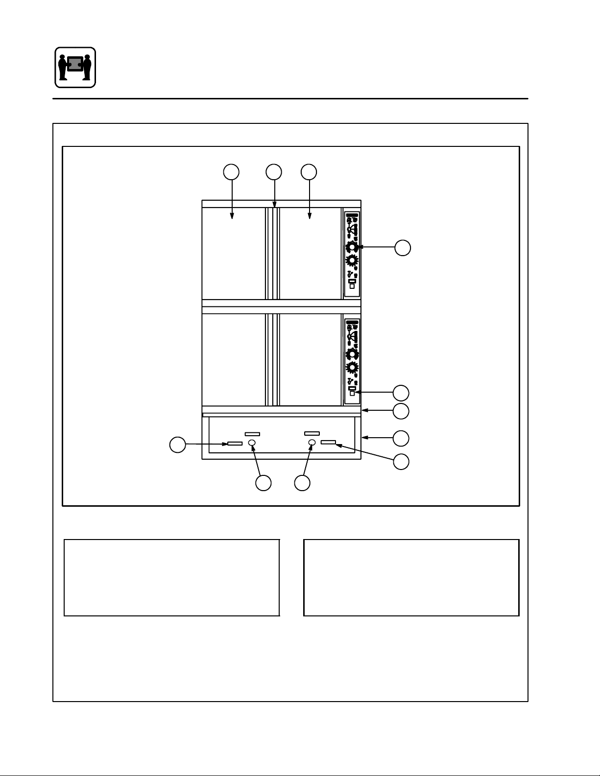
Oven Features
2 23
6
Standard Features
1
7
8
4
1
Control Panel
2 Oven Doors
3 Rotating Door Latch
4 Base Section
5
Figure 1
4
6
5
5 Deliming Port
6 Deliming Handle
7 Optional Meat Probe
8 Door Drip Pan
Page 16
Installation
General Installation Information
The purpose of the installation section of this
manual is to assist the designers and naval architects engineering the installation of a Blodgett
Combi COS-5HA Hatchable Combination Oven
into a new or existing ship.
Blodgett Combi has developed the COS-5HA to fit
in the same footprint as a Blodgett Mark V convection Oven. The COS-5HA Combination oven can
be used as a convection oven, steamer, or in a
“Combi” mode in which pulsed steam is combined with convection to provide faster cooking
and increase the moisture content of cooked
foods. Because of these features, the oven utilizes
water for generating steam. The Combi is a multisystem cooking oven and is more complex than a
convectional oven. Therefore, more attention has
to be paid to the installation process than that of
a convection oven.
The COS-5HA requires the following support systems:
D Power 440VAC,3phase,60ampservice
D Water Potable, 40 to 50 psi
D Drain Atmospheric vented drain,
1” minimum diameter
D Hood Air venting required for steam
removal
THE INSTALLATION INSTRUCTIONS CONTAINED HEREIN ARE FOR THE USE OF QUALIFIED INSTALLATION AND SERVICE PERSONNEL
ONLY. INSTALLATION OR SERVICE BY OTHER
THAN QUALIFIED PERSONNEL MAY RESULT IN
DAMAGE TO THE OVEN A ND/ OR INJURY TO
THE OPERATOR.
Qualified installation personnel are individuals, a
firm, a corporation, or a company which either in
person or through a representative are engaged
in, and are responsible for:
D The installation of electrical wiring from the elec-
tric meter, main control box or service outlet to
the electric appliance.
Qualified installation personnel must be experiencedinsuchwork,befamiliarwithallprecautions required and have complied with all requirements of state or local authorities having
jurisdiction.
Reference: National Electrical Code, ANSI/NFPA
70---Latest Edition and/or Canadian Electrical
Code CSA C22.1 as applicable.
This equipment is to be installed in compliance
with the Basic Plumbing Code of the Building Offi-
cials and Code Administrators International Inc.
(BOCA) and the Food Service Sanitation Manual of
the Food and Drug Administration (FDA).
5
Page 17

Installation
Delivery and Location
DELIVERY AND LOCATION
The COS-5HA hatchable combination oven is
shipped fully assembled on a special vibration resistant pallet. In addition, the oven is mounted on
two hardwood skids to facilitate removal from the
pallet. These skids were designed to match the
height of the separate installation base. This allows the assembled oven to be slid directly onto
the base after the installation base is mounted in
position and hard plumbed with potable water and
electric power.
COS-5HA dimensions:
Height 62.25” with legs
68.25” with 6” legs
65” with base
Width 38.19”
Depth 44.13”
The following clearances are required for the
COS-5HA:
Sides 0”
Rear 6”
UNPACKING
1. Remove the protective cover around the oven.
Inspect the unit for visible damage.
2. Remove the bolts that lock the 2-1/2” x 4”
hardwood skids to t he pallet base.
3. Us e a forklift to raise the oven assembly off the
pallet.Theskidscanbeleftinpositiontoassist
in moving an assembled oven onto the installation base or discarded after the oven assembly is unbolted into separate components for
passage through hatches.
ASSISTANCE
Blodgett Combi also provides engineering assistance when custom installation kits are required.
Our goal is to ensure that each oven installation
can be made in the most efficient and economical
manner.
For further information, please contact the Blodgett Combi Engineering Department:
D Phone 1-800-331-5842
D Fax 802-860-3702
6
Page 18
Installation
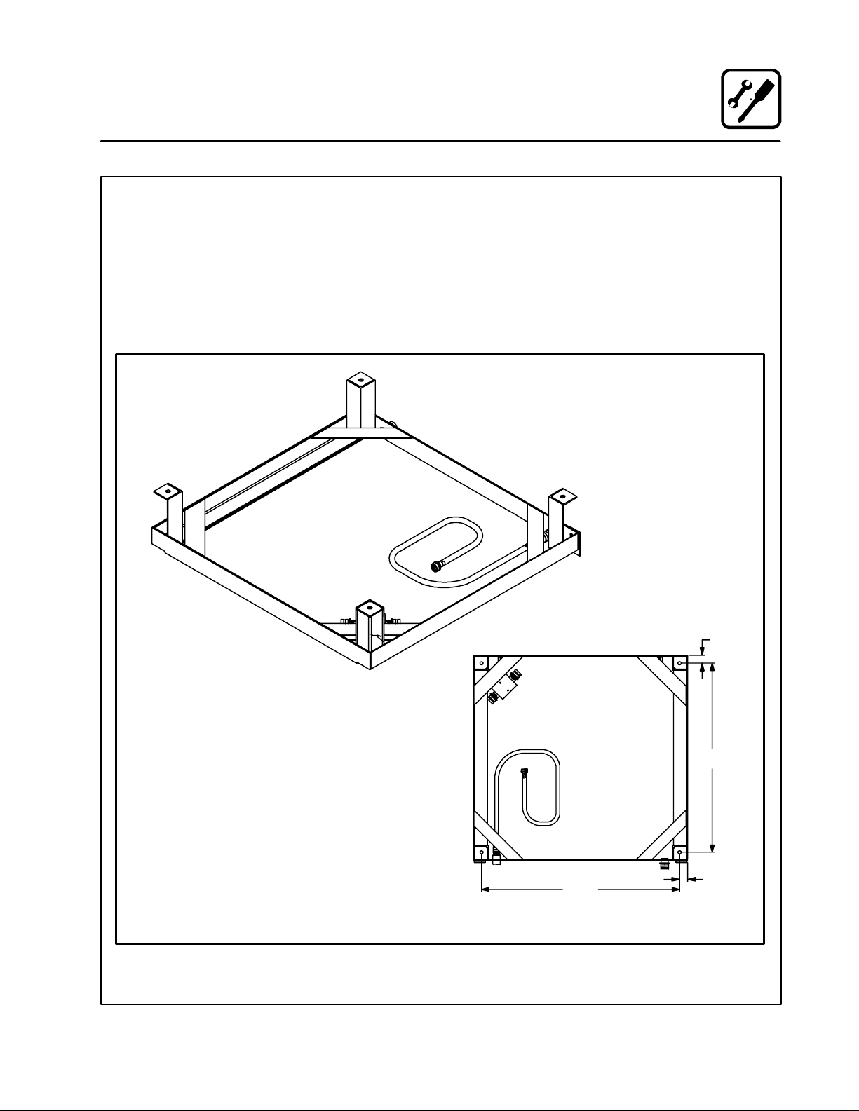
Installation Base
The Blodgett Combi COS-5H utilizes a stainless
steel locking installation base. The base is available with or w ithout legs. The installation base was
designed to facilitate the installation process and
to improve the access to the oven if and when major service is required.
Since the COS-5H is slightly narrower than the
installation base, multiple bases can be installed
side by side on the deck with no allowance for side
clearance.
1. Secure the 2-1/2” high installation base using
one of the following methods:
a.) Weld the base directly to the deck.
b.) Bolt the base to the deck.
2. Seal the base with an NSF approved sealant.
Base Shown Upside Down
INSTALLATION BASE WITH LEGS
Figure 2
BOTTOM VIEW
35.50
1.44
33.91
1.44
7
Page 19
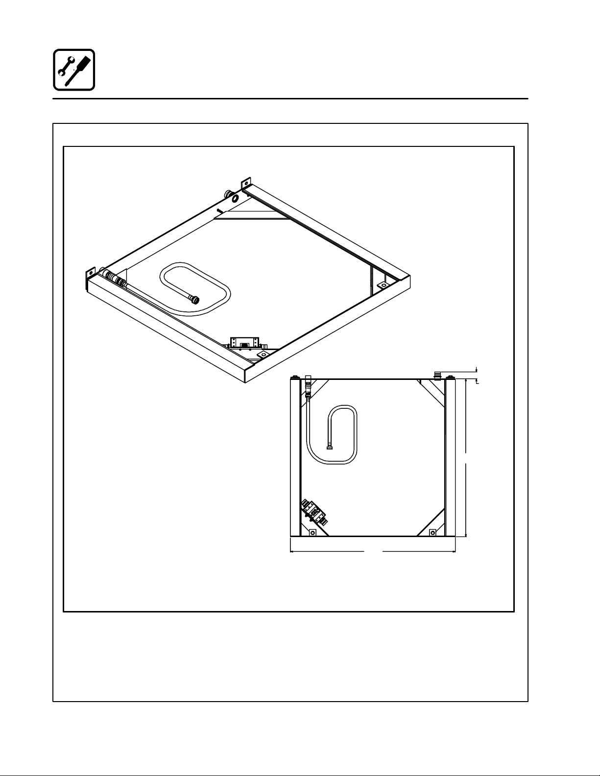
Installation
Installation Base
INSTALLATION BASE
Figure 3
1.56
36.78
38.37
8
Page 20
Installation
Utility Connections
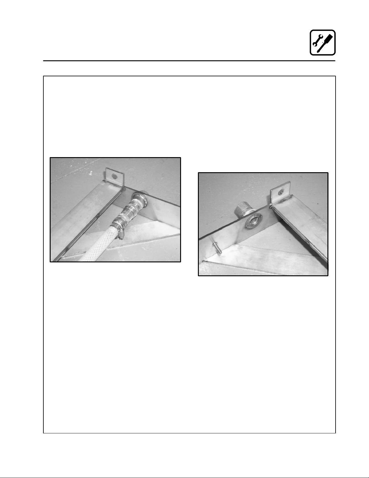
WATER CONNECTION
The oven requires access to potable water with a
pressure of approximately 40 to 50 PSI.
1. The water is connected to the rear of the installation base at the 3/4” NPT female coupling.
2. The water is directed to the oven through an
in-line pressure regulator and a flexible internal hose which connects to a fitting in the front
of the oven.
ELECTRICAL CONNECTION
The power requirement of the oven is 440 volt, 3
phase, 60 amp service.
1. The electrical service is brought into the oven
through the seal tight connector located on
therearoftheinstallationbase.
2. The power leads are brought into a splash
proof terminal box located in the front of the
installation base.
3. A grounding stud is supplied on the inside of
the installation base. See Figure 5.
Figure 4
DRAIN CONNECTION
An open drain s ystem utilizing a fixed funnel is recommended. For multiple oven installations, install
a deck mounted sloping drain with individual funnels positioned to accept the drain outlets of the
individual ovens.
Figure 5
9
Page 21

Installation
Oven Installation --- No Dismantling Required
Use this procedure if the oven a ssembly does not
have to be dismantled to bring it into the galley
where the installation base has been fitted.
1. Slide the oven assembly on the shipping skids
in front of the installation base.
2. Remove the two 1/2” bolts from the front of the
installation base. See Figure 6.
1/2” Bolt
Figure 6
3. U nscrew the front panel from the oven base
section. Leave the hoses connected to the
front panel and the oven base section.
4. Remove the two bolts securing the skids to the
front of the oven base section. See Figure 7.
1/2” Bolt
5. Removethetwoboltsandangleplatessecuring
the skids to the rear of the oven base section.
Bolt & Plate
Figure 8
6. Move the oven assembly to the installation
base as follows:
a.) Lubricate the top surface of the installa-
tion base with a little grease or silicone
spray.
b.) Slide the oven assembly off the skids onto
the tracks of the installation base.
c.) The locking pins on the rear of the oven
base section will fit into and lock the base
to the upright tabs attached to the installation base.
7. Reinstall the two bolts that were removed in
Step 2, from the installation base through the
oven base section into the installation base.
SeeFigure7forinstallationlocation.
8. Hook up water and electrical connections to the
oven base section. Apply NSF approved sealant to the cover of the splash proof terminal
box.
Bolt & Plate
1/2” Bolt
Figure 7
10
Page 22

Installation
Oven Installation --- Some Dismantling Required
Use this procedure if the oven a ssembly will be
dismantled to bring it into the galley where the
installation base has been fitted.
The assembled oven consists of three sections:
D
upper oven section
D
lower oven section
D
oven base section.
The oven base section consists of the major electrical components, steam generator, and the attachment components for mating the oven assembly to the installation base which is mounted
directly to the deck. In order to dismantle the oven
assembly, you will have to separate electrical w ire
harnesses and plumbing lines. We recommend
that you tape both sides of each electrical and
hose connection and mark them for easy identification during reassembly.
If you are installing more than one oven assembly,
keep all hardware and panels associated with one
oven assembly separate from the other oven assemblies. If the oven assembly has to be dismantled in order to fit through the hatches, use the
following procedure:
OVEN DISMANTLING
1. Remove the racks from the inside of both the
upper and lower oven sections. See Figure 9.
Figure 9
2. Remove the side support racks from the in-
side of both the upper and lower oven sections.SeeFigure10.
Figure 10
11
Page 23

Installation
Oven Installation --- Some Dismantling Required
3. Remove the drip pan from the front of both
ovens.SeeFigure11.
Figure 11
4. Remove the locking tab plate above the control panel by removing the Phillips screw. See
Figure 12. Do this to both the upper oven and
the lower oven.
5. Remove the control panel cover by lifting and
pulling the “D” handle toward you about 6”.
See Figure 13. Do this to both the upper oven
and the lower oven.
Remove Screw
Figure 12
Figure 13
12
Page 24

Installation
Oven Installation --- Some Dismantling Required
6. Remove the right side rear panel by sliding it
forward about an inch and then lifting the entire panel to free the retaining springs. See
Figure 14. Do this to both the upper oven and
the lower oven.
7. Cut the wire tie holding the copper drain tubes
together. See Figure 15.
Figure 14
Figure 15
13
Page 25

Installation
Oven Installation --- Some Dismantling Required
8. D isconnect the electrical wire harnesses (J1,
J3, J7, and J8) that connect the upper and
lower oven section to the oven base section.
See Figure 16. Mark connections prior to disconnecting for ease of re-assembly.
Disconnect
Figure 17
Figure 16
9. Disconnect and remove the steam lines to the
upper and lower oven sections at locations
shown in Figure 17 and Figure 18. The top of
thehoseissecuredwithabandclamp.The
bottom of the hose pulls out of the boiler in the
oven base section.
Disconnect
Figure 18
10. Remove the rear body panel on the lower oven
section.
14
Page 26

Oven Installation --- Some Dismantling Required
11. Remove the three bolts (1/2 inch diameter)
that connect the top and lower oven sections
together.
Two bolts are located in the rear upper left and
right corners of the lower oven section. These
bolts can be accessed from the back of the
lower oven section. See Figure 19.
The third bolt is accessed from the right side
of the lower oven section. It is located in the
upper right hand corner. See Figure 20.
Bolt
Bolt
Installation
Bolt
Figure 20
Figure 19
15
Page 27

Installation
Oven Installation --- Some Dismantling Required
12. Remove the upper oven section from atop the
lower oven section. Use care not to chafe any
of the harnesses that come from the base section. Use gloves to protect hands from any
sharp edges.
13.Removetherearbodypanelfromtheoven
base section. Unscrew the front panel from
the oven base section. Leave the hoses connected to the front panel and the oven base
section.
14. Removethefourbolts(1/2inchdiameter)that
connect the lower oven section and ovenbase
section together.
Two bolts are located in the rear upper left and
right corners of the oven base section. These
bolts can be accessed from the back of the
oven base section. See Figure 21 and
Figure 22.
The third bolt is accessed from the right side
of the oven base section. It is located in the upper front right hand corner. See Figure 23.
The fourth bolt is accessed from the left side
of the oven base section. It is located in the upper front left hand corner. See Figure 24.
15. Remove the lower oven section from atop the
oven base section. Use care not to chafe any
of the harnesses that come from the base section. Use gloves to protect hands from any
sharp edges.
Figure 22
Figure 23
Figure 21
Figure 24
16
Page 28

Oven Installation --- Some Dismantling Required
OVEN RE-ASSEMBLY
After the installation base is secured in position,
connected to potable water and electrical power,
the oven sections may be assembled onto it. In
galleys where ovens are located next to each other, the oven sections should be assembled prior to
sliding the oven assembly into the final position on
the installation base.
1. Remove the two 1/2” bolts from the front of the
installation base. See Figure 25.
1/2” Bolt
Figure 25
1/2” Bolt
Installation
4. Install t he four bolts (1/2 inch diameter) that
connect the lower oven section and ovenbase
section together.
Two nuts are located in the rear lower left and
right corners of the lower oven section. These
nuts can be accessed from the back of the oven
base section. See Figure 21 and Figure 22 on
page 16.
The third nut is accessed from the right side of
the oven base section. It is located in the lower
front right hand corner of the lower oven section. See Figure 23 on page 16.
The fourth nut is accessed from the left side of
the oven base section. It is located in the lower
frontlefthandcornerofthelowerovensection. See Figure 24 on page 16.
5. Install the rear body panel on the oven base
section.
6. Apply a 1/8 inch bead of clear silicone RTV to
the perimeter of the top edge of the lower oven
section. Lift the upper oven section onto the
lower oven section. Use gloves to protect
hands from any sharp edges.
2. Lubricate the top surface of the installation
basewithalittlegreaseorsiliconespray.Position the oven base section onto the flat track
surface of the installation base approximately
4” to 5”. Support the front of the oven base
section with a piece of 2” pipe (2-3/8” OD
approximately) by 39” (minimum) long.
3. Apply a 1/8 inch bead of clear silicone RTV to
the perimeter of the top edge of the oven base
section. Lift the lower oven section onto the
oven base section. Use gloves to protect
hands from any sharp edges.
17
Page 29

Installation
Oven Installation --- Some Dismantling Required
7. Install the three bolts (1/2 inch diameter) that
connect the top and lower oven sections together.
Two nuts are located in the rear lower left and
right corners of the upper oven section. These
nuts can be accessed from the back of the
lower oven section. See Figure 26.
The third nut is accessed from the right side of
the lower oven section. It is located in the upper front right hand corner of the upper oven
section. See Figure 27.
Bolt
Bolt
8. Install the rear body panel on the lower oven
section.
9. Install and reconnect the steam line to the upper oven section at locations shown in
Figure 28 and Figure 29. Secure the top of the
hose with a band clamp. Insert the bottom of
the hose in the fitting on the steam generator
intheovenbasesection.
Disconnect
Figure 28
Figure 26
Bolt
Figure 27
Disconnect
Figure 29
18
Page 30

Oven Installation --- Some Dismantling Required
10. Reconnect four electrical wire harnesses (J1,
J3, J7, and J8) that connect the upper and
lower oven section to the oven base section.
Installation
Top O v e n D r a i n
Figure 30
11. Locate the bag of parts inside the oven.
12. Install the barb fitting into the coupling to the
right of the copper drain tubes on the bottom
base of the oven.
13. Using the provided clamp, tighten the clamp
around the hose and barb fitting connection,
and the hose and reducer on the copper drain
assembly.
14. Wire tie the two copper drain tubes together
at location shown in Figure 31.
Bottom Oven Drain
Wire Tie
Figure 31
15. Review instructions in STEPS 1 thru 10 to ensure that all connections have been made properly, hoses are not kinked, and all electrical wire
harnesses are routed correctly to prevent chafe
or damage.
16. Complete the attached checklist document.
17. Replace oven electrical control panels on both
upper and lower oven sections. See Figure 13
and Figure 14.
18. Slide the oven assembly back onto the installation base. The locking pins on the rear of the
oven base section will fit into and lock the base
to the upright tabs attached to the installation
base. Install the two bolts (1/2 inch diameter)
removed in STEP 1 (Figure 25), thru the oven
base section and into the installation base. Insure that the drains from the upper and lower
ovens are located over the floor drain.
19. Hook up water and electrical connections to
oven base section. Apply NSF approved sealant to cover of splash proof terminal box.
INSTALLATION COMPLETE. PROCEED WITH
CHECK-OUT PROCEDURE.
1
2
3
Cold Plate Cooling
2
System Drain
19
Page 31

Operation
Oven Startup and Shutdown
OVEN START-UP
1. Turnthemodeswitchtothedesiredmode,
Steam, Hot Air, Combi, Cool Down.
STEAM MODE
1. Turn the mode switch selector knob to the
Steam Position. The green “POWER” indicator lamp illuminates on the front control panel.
2. Steam fills the cavity and is controlled by a
non-accessible internal thermostat.
Preheating for the STEAM mode
Before the first use of the appliance, daily or after
the oven has been idle for 3 hours, preheat with
the STEAM function until steam enters the oven
cavity. The appliance can then be loaded.
HOT AIR MODE
1. Turn the mode selector switch to the Hot Air
position. The green “POWER” indicator lamp
illuminates on the front control panel.
2. Set the Hot Air thermostat to the desired temperature. The Thermostat lamp illuminates indicating the cavity temperature is below the
desired set point.
3. When the cavity temperature reaches the desired set point, the temperature indicator lamp
goes off.
Preheating for the HOT AIR mode
COMBI MODE
1. Turn the mode selector switch to the Combi
position. The green “POWER” indicator lamp
illuminates on the front control panel.
2. Set the Hot Air thermostat to the desired temperature.
3. The hot air thermostat lamp illuminates, indicating the cavity temperature is below the desired set point.
4. Once the cavity temperature reaches the desired set point, the temperature indicator lamp
goes off.
5. The steam and hot air modes come on to satisfy the thermostat set points.
Preheating for the COMBI mode
Always preheat the appliance prior to loading.
Open the door and load the product quickly.
COOL DOWN
1. Turn the mode selector switch to the Cool
Down mode.
2. The convection blower comes on with the
door open or closed.
OVEN SHUT DOWN
1. Turn the mode selector switch to the off position.
Always preheat the appliance prior to loading.
Open the door and load the product quickly.
20
Page 32

Operation
Optional Meat Probe
CONTROLS IDENTIFICATION
1. MEAT PROBE SWITCH
Controls power to the meat probe.
2. MEAT PROBE CONTROL
Use to set the desired probe temperature. Indicates the actual temperature of the product
3. MEAT PROBE CONNECTOR
Receptacle for the plug in meat probe.
NOTE: For sanitation it is recommended that
the meat probe remain plugged into
the front panel receptacle at all times.
OPERATION
Measuring the product core temperatures during
long roasting periods is very practical. It is especially important for products such as Roast Beef to
reach a specific internal temperature.
Place the probe through to the middle of the product’s thickest section. B e sure the probe does not
touch any bone and the tip is not in a fat pocket.
These conditions can ca use inaccurate readings.
1. Set the MODE SELECTOR Switch to the de-
sired function.
2. Turn the MEAT PROBE Switch (1) to ON.
3. To set the desired core temperature press the
blueSETBUTTON(4)ontheMEATPROBE
CONTROL (2).
Use the up arrow key (6) to increase the setpoint temperature. Use the down arrow key
(5) to decrease the setpoint temperature.
Press the set button again to store the setpoint.
4. Set the TIMER to STAY ON. The cooking pro-
cess runs automatically.
When the selected core temperature is reached,
the buzzer will sound and the appliance shuts off
automatically.
The temperature and mode can be changed
at any time during the process.
5. Shut the appliance off by setting all switches
to OFF.
NOTE: When setting the internal temperature, be
sure to allow for carry-over cooking after
the roast is removed from the oven
1
2
3
Figure 32
21
WATLOW
1
2
RDY
SET
4 5 6
Page 33

Operation
Standard Controls
1
3
4
CONTROLS IDENTIFICATION
1. DON’T STEAM LIGHT
Indicates the unit is too hot to operate in the
steam mode. Place the unit in the Cool Down
mode until the temperature is below 230_F
(110_C). This light does not inhibit steam pro-
2
5
duction.
2. POWER ON LIGHT
Indicates the unit is in Steam, Hot Air or
Combi.
3. MODE SELECTOR SWITCH
Turns power to the oven on or off. Allows selection of Steam, Hot Air, Combi or Cool Down
Modes.
4. TEMPERATURE DIAL
Used to set desired cooking temperature.
5. HEATING INDICATOR LIGHT
Lights when the Hot Air heating is in operation.
6. TIMER DIAL
Used to set desired cooking time.
6
Figure 33
22
Page 34

OPERATION
1. Turn the MODE SELECTOR Switch (3) to the
desired function.
The POWER ON Light (2) illuminates.
2. Set the TIMER (6) for the desired cooking time
orsetittoSTAY ON. The buzzer sound and the
unit shuts off when the time has expired.
3. For the HOT AIR and COMBI modes, set the
TEMPERATURE Dial (4) to the desired cook
temperature. The HEATING INDICATOR Light
(5) illuminates and stays lit until the desired
temperature is reaches.
4. The selected mode operates automatically.
The temperature, time and mode can be al tered at any time during the cooking process.
The operation can be stopped by the use of
the Mode Selector Switch or by opening the
door.
Operation
Standard Controls
5. At the end of the specified time period, the
buzzer sounds and the appliance will shut off
automatically. Move the TIMER (6) to the STAY
ON position to stop the buzzer and restart the
unit.
6. To cool down the oven cavity, switch the
MODE SELECTOR Switch (3) to COOL
DOWN. In the Cool Down mode neither the
temperature dial or the timer will be operational. The blower will function with the door open
or closed.
7. The mode selector switch is also the main
power switch. In the OFF position the appliance is not operational.
NOTE: Always disconnect the power supply be-
fore servicing the unit.
23
Page 35

Cooking Guide
The Steam Mode
INFORMATION ABOUT THE STEAM MODE
How steaming works
This mode gently cooks food using non-pressurized steam. Fresh steam is directed into the oven
from the generator. It is not necessary to add water
to foods during the cooking process.
What can be steamed
Vegetables, side dishes, fish, meat, poultry, diet
foods, garnishes, dumplings, casseroles, meat
loaf, fruits, desserts and eggs.
How to operate the Steam mode
Simply turn the M ode Selector Switch to the
STEAM position and set the Timer.
Theadvantagesofsteaming
Steaming is a well-known cooking process frequently used in restaurant and institutional kitchens. With this appliance it is now possible to enj oy
the many advantages of steaming, some of which
are:
DDDD
Shorter Cooking Times
The continuous processing of large amounts of
product is no problem and long cooking times
arenolongernecessary.Evenwithfullloads,
relatively shorter cooking time for food is needed.
DDDD
High Quality Foods
With the useof steam, valuabletaste and aroma
are preserved since steamed foods retain their
own natural taste. During the steaming process
foods retain the nutrients and vitamins w hich
are lost in water during boiling. Therefore, when
compared, steamed foods have much better
color than foods that have been boiled. Also, by
using shallow containers the product is not layered as deeply and mushing is avoided.
DDDD
Vitamin Retention
Vitamins are not destroyed. This is due to the
shorter cooking times, the use of less or little
water and the use of a low temperature; slightly
less than 212_F/100_C.
DDDD
Firmness
With the use of steam, overcooking is not a
problem and firmness can be individually controlled.
DDDD
Simultaneously Steaming Different Foods
Thereisnoflavortransferwhencookingwiththe
STEAM mode. For this reason, various types of
food with different cooking times can be loaded
or removed at any point during the cooking process.
24
Page 36

Cooking Guide
The Steam Mode
TIPS AND PROCEDURES
Containers
Both solid and perforated steam table pans of varying sizes (full, half, and one-third size) may be
used in the appliance. Small pans may be placed
on wire racks.
Stocks for Sauces
When trays are used for cooking there is usually
enough stock collected for making sauces. When
using perforated pans, insert a solid pan in the bottom rack to collect the stock.
Seasoning
Since there is no liquid added during the steaming
process, season using one of the following methods:
DDDD
Season before cooking: Sprinkle the spice
mixture evenly over the food prior to cooking.
DDDD
Oil seasoning after cooking: Stir the oil mixture into the product. Steam again for two minutes in some cases.
Blanching and Prep Work
Large amounts of product can be blanched in a
short amount of time. T rays should not be filled
higher than 3 inches.
The STEAM mode is excellent for preparing vegetables for peeling.
Canning and Preserving
The diameter of the containers must not exceed
4-5 inches when canning.
Thawing
Thawing time is much shorter when using steam
and produces higher quality food.
Reheating
The use of steam creates an even distribution of
heat, which gives food better taste and retention
of nutrients.
Foods a re reheated in the trays in which they were
cooked. Reheating times vary according to the
height and content of the containers.
SAMPLE DISHES
Vegetables
Fresh and frozen vegetables may be steamed together. Frozen vegetables should be loosely scattered on the trays. Perforated trays shorten cooking time, although solid trays may be used.
Cooking times will vary depending on the quality
of the vegetables. When steaming fresh vegetables, check the product
cooking period.
Steamed vegetables tend to soften after cooking.
Sincethereisadelaybetweencookingandserving,
it is best not to steam vegetables too soft. This is
especially important for foods prepared for transport.
Rice and Potatoes
Rice requires the addition of water for steaming.
Remember that the rice continues to s w ell after
cooking; plan your quantities accordingly.
Always cook potatoes in perforated pans. Steam
can permeate the potatoes better if they are quartered through the width and not the length.
Eggs
Eggs are inserted onto wire racks, either in t he
cardboard container or placed into perforated
trays (there is no need to puncture them). Cooking
eggs with the STEAM function saves work and results in less waste since steamed eggs do not
break. Also, the degree of hardness can be controlled exactly. Begin timing w hen the oven window is misted over.
Fish
Fish can be steamed in trays w ithout using extra
stock. Use a 1 inch pan for fresh fish (Fillets). For
larger or frozen pieces, use a 2 inch pan.
Poachedfish can be prepared with aromatic herbs
and vegetables in either solid or perforated pans.
Steam w ithout stock.
Shell fish can be steamed in perforated pans. Use
a solid pan to catch drippings for stock.
3
/4of the w ay through the
25
Page 37

Cooking Guide
The Hot Air Mode
INFORMATION ABOUT THE HOT AIR MODE
How cooking with hot air works
Hot air is circulated at high speed on all sides of
the product, providing a concentrated cooking
process. This function is extremely effective for intensive browning.
What can be cooked with hot air
Hot air can be used for all foods which need a short
cooking time and intensive browning. For example: steaks, cutlets, fillets, breaded foods, and various baked foods. This function may also be used
for au gratin.
COOKING WITH THE HOT A IR MODE
Temperatures
For intensive browning and crispy crusts, preheat
the oven to the maximum temperature of
500_F/260_C. This is especially important when
searing.
Performance
The charts showing performance examples (See
Cooking Guide) are based on full capacity. Better
results may be obtained by reducing product
quantities.
Cooking Times
Due to the constant hot air circulation, this appliance cooks faster than conventional grills and
deck ovens.
Cooking times will vary according to the quality,
weight, and height of the product.
Trays or Racks?
This is a question of individual choice. Racks have
the advantage of browning food on all sides; the
underside of tightly packed foods may be lighter
when using trays.
TIPS AND PROCEDURES
Loading the Oven
Place like sized product together on one rack. In
order to ensure proper air circulation, racks and
trays s hould not be crowded.
Oiling
The quality of some foods, such as steaks and
breaded meats, can be enhanced by coating with
oil or a paprika oil mixture.
Breaded Foods
The degree of browning is dependent on the
amount of raw material in the breading. Oil can be
used to intensify the browning. Press the breading
firmly but don’t overload the oven. Flouring seared
foods is not recommended.
Baking
Forbaking,theModeselectorswitchmaybeset
to HOT AIR, STEAM, COMBI or any combination
according to the type of product. Steam added to
the baking process opens up a wide range of possibilities:suchashardcrustsandgoodshineon
certain types of breads. Here are some tips for
baking:
D
Preheat oven to the baking temperature.
D
Baking temperatures can generally be set
50-75_F/20-25_C lower than with a conventional baking or roasting oven. When in doubt, lower the temperature.
D
The baking time can be shorter than with conventional methods.
D
Slightly reduce your quantities of mixtures with
excessive moisture.
D
Use deep trays for light mixtures in order to ensure undisturbed baking. Baking forms should
not be higher than 3 inches.
D
Cake forms (pans, tins, etc.), should be placed
on racks.
D
Distributefoods evenly w hen loadinghalf loads.
D
Use every second tier for baking bread, heavy
mixtures (yeast doughs, etc.) and well filled
forms.
26
Page 38

Cooking Guide
The Combi Mode (Steam and Hot Air)
INFORMATION ABOUT THE COMBI (STEAM
AND HOT AIR) MODE
How Combi Mode Works
With this function, the advantages of steam (short
cooking time, less shrinkage) and hot air (intensive aroma, appetizing color) are combined.
Steam and hot a ir circulate at high speeds, enveloping the product on all sides and providing an intensive cooking process.
What can be cooked in Combi mode?
All types of roasts, duck ling, pork, beef, lamb,
meat loaf, ground chuck foods, casseroles, poultry, stuffed vegetables, vegetables au gratin and
yeast doughs.
TheadvantagesofCombimode?
DDDD
Productivity
Previously, several different appliances, and
multiple procedures, were necessary to combine heat andsteam preparation. Now all of
these methods can be used without time wasting interruptions, with one appliance.
DDDD
Less Shrinkage
The usual weight loss during roasting in conventional appliances can be reduced by approximately 13% of the original weight.
DDDD
Juiciness and Crunchy Crusts
When used at the beginning of the cooking procedure, the searing action of steam instantly
closes all pores. This reduces the loss of protein
and meat juices. Therefore, products with long
roasting times remain juicy. Foods retain their
moisture and roasts develop a pleasing color as
well as an appetizing crust. Meats have a pronounced roasted taste and burning of the surface is almost impossible.
COOKING IN THE COMBI MODE
The COMBI function can be used for the entire
cooking process or for any portion of the cooking
procedure you desire.
What do Combi-roasting, Combi-steaming and
Combi-baking mean?
We have created these names since both modes,
STEAM and HOT AIR, can be applied in any combination as follows:
D
Together, as in the COMBI function.
D
In sequence
Example: first STEAM and then HOT AIR.
D
Orinsequenceandthenincombination
Example: first HOT AIR and then COMBI
Or conversely: first COMBI and then HOT AIR.
D
Or all three functions in sequence
Example: first STEAM, then HOT AIR, then
COMBI.
For additional tips on when to use each of these
Combi Modes see the “Summary of Functions” on
the following page.
27
Page 39

Cooking Guide
Summary of Functions
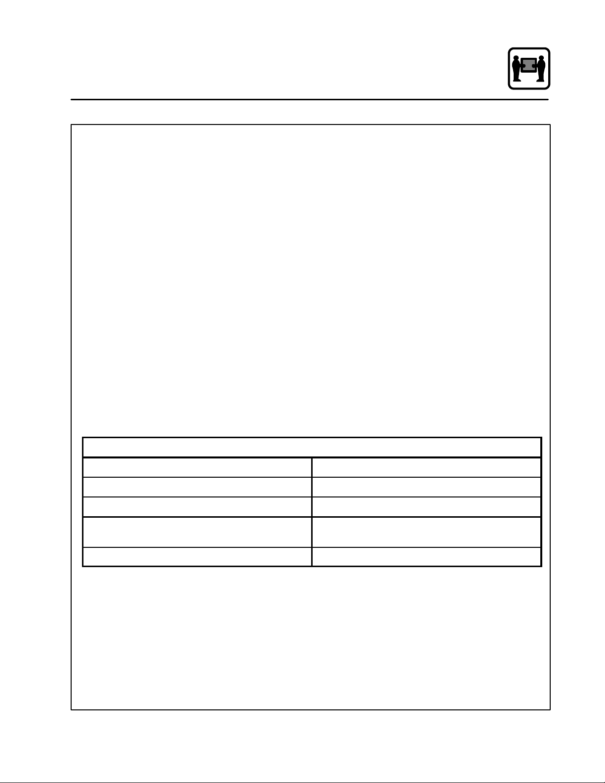
MODE SELECTION COOKING METHODS PRODUCTS
Steam
Hot Air
Combi
Steam Hot Air
Hot Air Combi
Steaming, defrosting, thawing, reheating-reconstituting, blanching,
preserving, poaching, simmering,
braising, stew ing.
Roasting, grilling, baking,
au gratin.
Combi-steaming, Combi-roasting,
Combi-baking, defrosting-thawing,
reheating-reconstituting.
Combi-steaming,
Combi-braising,
Combi-roasting,
Combi-baking,
(Begin with steam, then with dry heat
for crusting, browning, gratinating.)
Combi-steaming,
Combi-roasting, Combi-baking,
(Start with dry heat, switch over to
Combi for slow but gentle even
browning, switch back and forth as
necessary.)
Convenience food, potatoes, rice,
fresh or frozen vegetables, fresh or
frozen fish, poultry, meat, fruit, eggs,
puddings, casseroles.
Roast beef, pork, veal, lamb, chicken, hamburger, fish, stuffed vegetables,toast,lasagne,potatoes,pies,
shortbread, puff pastry, Danish and
French pastry, bread.
Prime rib, whole bone ham, goose,
turkey, fish, mutton, beef, pork roast,
French pastry, bread, rolls, puff
pastry, Danish pastry, convenience
food.
Stuffed peppers, gratinated vegetables, fennel, broccoli, cauliflower ,
rack of lamb, pork
French pastry, puff pastry, yeast
dough, turkey, duck, goose, lamb,
stuffed vegetables.
Combi Hot Air
Steam Hot Air Combi
Combi-braising,
Combi-roasting,
Combi-baking,
(Start with Combi, finish with dry heat
for crusty, crisp, brown surface,
switch back and forth as necessary.)
Combi-steaming,
Combi-roasting, Combi-baking,
(For meats: sear pores closed with
steam, then brown with dry heat, then
switch between Combi and dry heat.
For stuffed vegetables: steam first
and switch between dry heat and
Combi during the rest of the cooking
process.)
28
Whole bone ham, ham in bread
dough (English Ham), whole fillets of
beef, pastry dough, yeast dough
(bread, rolls).
Veal, pork, beef, leg of lamb, goose,
duck, turkey, prime rib, puddings,
stuffed peppers; ideal for all products which need a humid cooking
process.
Page 40

Cooking Guide
General Tips and Procedures
USING RACKS
Use racks for roasts needing a longer roasting
time, large roasts (pork, veal, beef, venison,
lamb), searing, toast, au gratin, (chicken, duck,
goose, legs, chops), cooking in containers, thawing, baking in tins, etc. When cooking in racks it is
important to turn food products.
USING PANS
DDDD
1I Deep Steam Table Pan
Forfried potatoes, hamburgers, au gratin, thawing, meat loaf, meat balls, fried, poached and
steamed fish, baked goods, vegetable casseroles, duck and goose.
DDDD
2I Deep Steam Table Pan
For cabbage rolls, stuffed peppers, stews, rice,
vegetables, sauerkraut, assorted fruits and
compote. Also for collecting stock, preparing
sauces, etc.
DDDD
2½IDeep Perforated Steam Table Pan
For vegetables without stock, side dishes
(breads) and products with shorter cooking
times.
DDDD
4IDeep Perforated Steam Table Pan
For vegetables (blanching spinach for example), potatoes, shelled or unshelled eggs.
DDDD
6IDeep Perforated Steam Table Pan
For potatoes.
LOADING THE OVEN
To ensure that the product will brown on all sides,
do not place foods too close together. Place the
grain of meats parallel to the air stream (left to
right). This ensures better absorption and shortens the cooking process. Place like sized pieces
together on the same rack, smaller pieces cook
more quickly.
Place the food in the appropriate pans/trays or distribute it on the racks. Insert racks and trays into
the pan rack. It is recommended that the pan rack
be loaded outside of the oven wh en processing
large amounts of product. The pan rack for table
models is well suited for this purpose; it allows for
a higher hourly production and an efficient w ork
sequence.
REMOVING THE PRODUCT
Turn the Mode Selector Switch to OFF before
opening the appliance door.
NOTE: Open the door slowly after steaming! Hot
Steam Will Be Present!
COOKING TIMES
The length of the cooking process depends on the
quality, weight and thickness of the food product.
TEMPERATURES
Typically, the longer the cooking process, the lower the temperature.
29
Page 41

Cooking Guide
Suggested Times and Temperatures
PRODUCT SUGGESTED CORE TEMPERATURE
Beef
Fillet of Beef
Roast Beef
Pot Roast
Veal
Saddle of Veal
Loin
Shoulder
Stuffed or Boned
Leg, Top-side
Pork
Leg
Picnic Shoulder
Ham
Smoked Pork Chops
Ribs
Tongue
medium rare
medium rare
well done
medium
well done
well done
fricandeau
well done
well done
juicy
well done
well done
130_-140_F
130_-140_F
170_F
160_F
165_-175_F
165_-175_F
165_-170_F
172_F
185_F
185_F
155_F
158_F
150_F
195_F
54_-60_C
54_-60_C
78_C
70_C
75_-80_C
75_-80_C
75_-78 _C
78_C
85_C
85_-80_C
68_C
70_C
70_C
90_C
Poultry
Chicken
Goose
Tur k ey, Du ck
Lamb
When the meat is well done it has a core temperature between 173_-185_F(79_-85_C). The core has
a slightly pink color and the juices are clear.
Saddle
Saddle
Leg
Leg
Pâtés
Pâté 160_-165_F72_-74_C
NOTE: Actual temperatures may vary from those shown. Write in your proven temperatures for ready ref -
erence.
well done
well done
well done
slightly pink
well done
slightly pink
well done
185_F
195_-198_F
175_-185_F
158_-165_F
175_F
165_-170_F
180_-185_F
85_C
90_-92_C
80_-85_C
70_-75_C
80_C
75_-78_C
82_-85_C
30
Page 42

Cooking Guide
Notes
31
Page 43

Maintenance
Cleaning and Preventive Maintenance
CLEANING THE INTERIOR
Daily cleaning of the appliance is essential for sanitation, and to ensure against operational difficulties.
For difficult cleaning, allow the spray-on oven
cleaner to work longer before rinsing.
1. Cool the oven down to 140_F/60_Cor,ifthe
oven has been idle, turn the steam mode on
for 3 to 4 minutes in order to warm the oven
surfaces.
2. Spray the interior of the oven with a cleaning
solution.
NOTE: Never spray water into the unit when
the temperature is above 212_F. N E V ER SPRAY WATER IN THE UNIT AFTER
USING THE HOT AIR OR COMBI
MODES.
3. Let the cleaner work for 10 to 20 minutes with
the oven off. For difficult, baked on grease,
etc. allow to work over night.
4. Set the timer for 15 to 20 minutes.
5. Set the mode selector switch to Steam. This
will soften all burned on residue.
6. Rinse the oveninteriorwith w a ter (a hose may
be used, but take care that only the oven’s interior cavity is sprayed with water).
7. Setthe mode selectorto steam for anotherfive
minutes to flush out the oven interior and remove all detergent residue.
NOTE: The oven cavity should never be scoured
or scraped.
On stainless interiors, deposits of baked on splat ter, oil, grease or light discoloration may be removed with a good non toxic industrial stainless
steel cleaner. Apply cleaners when the oven is
cold and always rub with the grain of the metal.
The racks, rack supports and the blower wheel
maybecleanedintheovenorbyremovingthem
from the oven and soaking them in a solution of
ammonia and water.
NOTE: DO NOT use corrosive cleaners on the
Oven/Steamer.
CLEANING THE EXTERIOR
Oven exteriors may be cleaned and kept in good
condition with a light oil. Saturate a cloth and wipe
the oven when it is cold; wipe dry with a clean
cloth.
NOTE: The outside of the appliance is not to be
sprayed with water.
PREVENTIVE MAINTENANCE
The best preventive maintenance measures are
the proper initial installation of the equipment and
a program for cleaning the oven routinely. The
Oven/Steamer requires no lubrication. Contact
the factory, the factory representative or a local
Blodgett Combi service company to perform
maintenence and repairs should they be required.
WARNING!!
Disconnect appliance from power supply
before servicing or cleaning.
32
Page 44

Maintenance
Decalcification
The COS-5HA has a separate boiler for each unit.
There are deliming ports and handles for each boiler
located on the base unit. The left deliming port and
handle is for the bottom unit. The right deliming port
and handle is for the top oven. To save time the boilers should be delimed simultaneously.
The COS-5HA should be delimed on a monthly basis regardless of water quality or usage. Use the
following procedure to delime the boilers.
WARNING!!
ALWAYS USE PROPER SAFETY EQUIPMENT WHEN DELIMING. Gloves and eye
safety equipment are recommended.
1. Set both mode selector switches to Steam
mode. Wait until steam is produced. This will
ensure that the water in the steam generators
is hot.
2. TurnthemodeselectorswitchestoOFF.
3. Remove both deliming port covers on the
base unit.
4. Add 10 ounces of deliming solution to the de-
liming bottle and then add 1-3/4 gallons of
warm water.
NOTE: Lime-a-way
are recommended. The main active
ingredient should be a deluted concentration of phospheric acid.
5. Delime the boilers as follows:
a.) Connect the deliming hose to one of the
deliming ports on the base section.
b.) Turn the corresponding red deliming han-
dle on the base unit so it is vertical. This
opens the deliming port.
c.) Pump in all of the solution.
d.) Close the deliming handle and remove
the deliming hose from the deliming port.
Thehandleisnowhorizontal.
6. Repeat STEPS 4 and 5 for the other oven.
7. Allow the ovens to sit with the deliming solution in them for at least 1/2 hour.
NOTE: For heavy lime build up, allow to stand
for 1 hour.
t
or a generic equivalent
8. Drain and flush the boilers as follows:
a.) Connect a drain hose to one of the delim-
ing ports. Allow the boiler to drain completely. The drain hose is not supplied.
b.) Carefully rinse out the deliming container
and fill it with 1-3/4+ gallons of fresh water
only.
c.) Turn the oven to Steam and allow the boil-
er to fill. Wait at least 2 minutes.
d.) Connect the deliming pump to the same
deliming port on the base section.
e.) Turn the red deliming handle on the base
unit so it is vertical. This opens the deliming port.
f.) Pump in all of the water in the deliming
pump.
g.) Close the deliming handle and remove
the deliming hose from the deliming port.
Thehandleishorizontal.
h.) Connect the drain hose to the same de-
limingportonthebasesection.
i.) Turn the red deliming handle on the base
unit so it is vertical. This opens the delim-
ing port.
j.) Let all the water drain from the boiler.
k.) Remove the drain hose and turn the han-
dle to the horizontal position.
9. Repeat STEPS b. and 8 for the other boil er.
10. Reattatch the covers to the deliming ports.
Deliming
Deliming
Port
Port
33
Figure 34
Page 45

Maintenance
Troubleshooting Top Oven Section
COOL DOWN MODE
POSSIBLE CAUSE(S)
SYMPTOM: Motor doesn’t run in cool down.
S
Blown 2 amp input fuses.
S
Transformer is defective
S
Blown 2 amp secondary fuse.
S
P13 snap disk on the solid state relay assembly
is open (SSR assembly is to the left of the boiler)
S
Mode selector switch (S1) is not closing
between 23 & 24.
S
Motor contactor (K1-A) is not pulling in.
S
Motor protector (PKZM-A) has tripped.
S
Convection motor is bad.
SUGGESTED REMEDY
S
Remove and check fuses. Determine cause of circuit overload.
S
Verify input to transformer. Check transformer
coils. Approximately 2.2 ohms primary / .7 ohms
secondary. Replace if necessary.
S
Remove and check fuse. Determine the cause of
circuit overload.
S
Verify water is on ohm out snap disk P13
S
Check closing of switch with meter. Replace if
needed.
S
Verify voltage to coil A1 to A2 of motor contactor.
(Coil resistance is 500+ ohms) Replace if defective.
S
Motor protector is defective or see “Convection
Motors Run Intermittently” below.
S
Check windings of coil motor. Resistance of
windings is approximately 85 ohms. Running
current .5 amps.
SYMPTOM: Convection motor runs intermittently.
S
Thermal overload on motor (M1) is opening and
closing (automatically resets when cooled).
S
Electrical compartment cooling fan is not running.
NOTE: SSR refers to Solid State Relays which are
water cooled on a cold plate.
S
Check current draw. See if motor seal is out of
alignment. (Requires removal of blower wheel.)
Adjust seal if needed. Evaluate motor. Replace if
defective.
S
Check windings on fan (600+ ohms coil resistance) if open, replace.
34
Page 46

Troubleshooting Top Oven Section
HOT AIR MODE
NOTE: Confirm cool down works before proceeding with hot air.
Maintenance
POSSIBLE CAUSE(S)
SYMPTOM: Mode switch is in the hot air position but no control panel lights are on.
S
Cavity high limit (F3) is open. (opens at 662_F)
S
Power on light (H4) has 220V but is not lit.
SYMPTOM: Hot air temperature light (H5) will not come on but power on light (H4) is lit.
S
Oven is up to temperature.
S
Mode selector switch (S1) is not closed betw een
terminals 9 & 10.
S
Door switch (S2) is not closing.
S
Relay (R5) is open.
S
Hot air thermistor is out of tolerance. Unplug from
thermostat and check resistance. (Use ohm chart)
Replace if needed.
S
Defectivehotairthermostat.Replace
S
Cavity high limit is defective. Replace
S
Replace light (H5)
S
Everything is OK.
S
Defectivemodeselectorswitch(S1).Replace
switch.
S
Proximity door switch (S2) is not engaging. Remove access plate & inspect. Replace if defective.
S
Optional meat probe control has reached temperature and s hut off oven by supplying 220V to
terminals 7 & 8 on (R5).
SUGGESTED REMEDY
S
Timer (S4) has timed out to zero minute position.
S
Defective timer (S4).
S
Relay (R5) is defective. Replace
S
Reset timer to a timed position or fully into the stay
on positio n if continued operation is desired.
S
Replace timer (S4). Verify voltage 220V is present on terminals 6 & 7 before replacement.
35
Page 47

Maintenance
Troubleshooting Top Oven Section
HOT AIR MOD E (continued)
POSSIBLE CAUSE(S)
SYMPTOM: Hot air temperature light (H5) will not come on but power on light (H4) is lit. (continued)
S
Hot air thermostat (P5) is not getting 220V at
inputs L1 and C.
S
Hot air thermostat (P5) is getting voltage 220V to
inputs but has no 220V to terminal “NO” and
common.
SYMPTOM: No heat in Hot Air Mode but hot air (H5) and power light (H4) are both on.
S
Motor is running and the centrifugal switch is
open.
S
Hot air SSR (K2-A) does not pull in.
S
Hot air SSR (K2-A) is energized 220V at coil but
no heat.
S
Check wire connections.
S
Hot air thermistor probe is bad or out of tolerance. Refer to OHM chart. Replace if needed.
77 = 100,000 212 = 6,780 347 = 1,070.
S
Defective hot air temperature control (P5). Replace.
S
OHM out switch (red wires in motor) while motor
is running, if it is open, remove motor and inspect
centrifugal switch through access plate for loose or
disconnected wires. Replace if defective. If you replace a motor, always replace the motor seal.
S
Verify 220V to coil. Replace if needed. See if red
LED is on.
S
Contactor is not closing on one or more poles.
Replace.
SUGGESTED REMEDY
S
Hot air elements are open. Replace as needed.
SYMPTOM: Oven appears to be working properly, but the bake pattern has changed or is uneven.
S
Oneormorehotairelementsareopen.
S
Check continuity of elements. Replace as needed.
36
Page 48

Maintenance
Troubleshooting Top Oven Section
STEAM MODE
NOTE: Confirm cool down and hot air modes work before continuing. By checking hot air mode first, you
have trouble shot all common components in both the hot air and steam mode up to and through
the timer (S4).
POSSIBLE CAUSE(S)
SYMPTOM: Mode switch is in the steam mode position but power light is off.
S
Mode selector switch (S1) is not closed betw een
terminals 3 & 4.
S
Power on light (H4) is defective.
S
High limits F3 has tripped.
SYMPTOM: Steam generator overfills.
S
Float assembly is hanging up.
S
Relay R2 is stuck close
S
Solenoid is staying open.
S
SYMTOM: TO HOT FOR STEAM light is on.
S
Defectivemodeselectorswitch(S1).Replace
mode switch.
S
Replace light.
S
Return to Troubleshooting Hot Air Mode.
S
Delime steam generator / remove float assembly
if needed and clean / move float assembly up /
down, verify reed switch is opening & closing
with VOM
S
Verfy coil (7 & 8) has no power to it, replace R2
relay.
S
Replace if needed.
S
TOO HOT FOR STEAM light is a information light
only, if it is “ON” it does not affect operation
S
Open door and cool down cooking cavity if TOO
HOT FOR STEAM light comes on in the steam
mode, P1 is defective.
SUGGESTED REMEDY
37
Page 49

Maintenance
Troubleshooting Top Oven Section
STEAM MODE (continued)
POSSIBLE CAUSE(S)
SYMPTOM: Mode switch is in the steam mode, power on light is on, but no steam.
NOTE: If the water level is not maintained properly, a safety F6 --- A (caliary type thermostat, opens
at 275F & must be manualy reset) Before continuing, review the sequence of operation to
understand the float circuit / fill logic.
S
Mode switch terminals 1 & 2 open
S
Mode switch terminals 5 & 6 open
S
Boiler high limit F6-A has tripped. (Also review if
you are having water fill issues)
S
Boiler is not filling deliming port to determine if
boiler has water
S
Use VOM to ohm out terminals, replace mode
switch in needed
S
Use VOM to ohm out terminals, replace mode
switch in needed
S
Continued resetting of F6-A boiler high limit may
weaken the high limit and cause premature tripping.
S
Ball float is hung up in boiler and staying open.
Ohm out between R1 relay terminal 2 & R2 relay
terminal 7 Removal of float assembly may be necessary to determine if float is hanging up due to
mineral build up or internal reed switch has failed.
S
Quesent timer is not supplying flat water check (90
secondson/10off)veritypowerinonbothinputs,
terminals 2/3 & 7/3. Verify output on terminal 4.
S
Relay R1 supplies power to the float / verify terminals 6 to2 are closed.
SUGGESTED REMEDY
SYMPTOM: Steam contactor K3-A is not engaged.
S
Defective SSR / See if RED LED on SSR is lit
S
Steam solid state contactor K3-A has power in to
input, but no heat.
S
Relay R2 supplies power to the fill solenoid /
verify the terminals 7 & 8 have power (relay coil)
/ verify terminals 5 to 3 are closed.
S
Coil for the fill solenoid Y1 is open / verify input.
Ohm out coil windings, should be approximately
1800 ohms. Replace Yi if needed.
S
Verify power to coil / replace if needed
S
Solid state contactor is not closing on one or
more poles. Replace.
S
Steam elements are open. Ohm out elements.
Replace as needed.
38
Page 50

Maintenance
Troubleshooting Top Oven Section
COMBI MODE
NOTE: Confirm cool down, hot air and steam modes work before continuing. By confirming previous
modes you have tested most of the components in Combi.
POSSIBLE CAUSE(S)
SYMPTOM: Mode switch is in the Combi position but no control panel lights are on.
S
Mode selector switch (S1) terminals 21 & 22 are
open.
SYMPTOM: Power light (H4) is on, hot air heat light (H5) is on and off, but no steam.
S
Mode selector switch (S1) terminals (15 & 16) or
(17 & 18) are open.
S
Solid state combi timer is not operating. (no
steam in the combi mode only)
SYMPTOM: Power light (H4) is on, steam works, but no hot air.
S
Mode selector switch (S1) terminals 19 & 20 are
open.
S
Replace switch.
S
Replace sw itch.
S
Verifyresister assembly (with adjusting knobs) is
plugged fully in
S
Verity power in on terminals 2 & 3
S
Verify output on terminal 1
S
Verify timer knob settings (15 sec “on” / 45 sec
“off”)
S
Replace sw itch.
SUGGESTED REMEDY
SYMPTOM: Not enough steam in the Combi mode.
S
Cavity temperature is too high (over 400_F)
S
Timing sequence needs adjusting to increase
steam.
S
Reduce temperature.
S
Left knob is time “ON” /right knob is time “OFF”
39
Page 51

Maintenance
Troubleshooting Top Oven Section
SEQUENCE OF OPERATION -- HOT AIR
NOTE: Electricity flows through these components
in the order listed.
1. Terminal block L1, L2, L3 (440V/3ph)
2. Primary 2 amp slow blow fuses F2 / F3
3. Primary coil of transformer (step down 440V
to220V)
4. Secondary coil of transformer 220V
5. Secondary 2 amp slow blow fuse F1
6. P13 Solid State cold plate snap disk high limit
(opens at176F)
7. Plug connector (J3) terminal 9
8. Cooking compartment high limit (F3) terminals 1 to 2
9. Plug connector terminal 2 (J9)
10. Mode selector switch (S1) terminal 9 to 10
11. Power ON light (H4)
12. Plug connecter terminal 5 (J9)
13. Electrical compartment cooling fan (CF)
14. Door switch (S2)
15. Plug connector (J9) terminal 13
16. Meat probe relay (R5) terminal 6 to 1
17. Timer (S4) terminals 4 to 6 or Timer (S4) termi nal 4 to 5 if timer is timed out
18. Buzzer (T1)
19. Plug connector (J9) terminal 11
20. Plug connector (J3) terminal 1
21. Power junction: to follow motor operation to
step 26.
22. Motor contactor (K1-A) terminal A1 to A2
23. Power in L1, L2 & L3 (440V/3ph) motor contactor (K2-B)
24. Motor protector (PKZM-A)
25. Plug connector terminal 1, 2 & 3 (J1)
26. Convection motor
27. Mode selector switch (S1) terminal 11 to 12
28. Hot air thermostat (P5) C to L1
29. Hot air thermostat (P5) COM to NO
30.Hotairlight(H5)
31. Plug connector (J9) terminal 10
32. Motor centrifugal switch (CS1)
33. Plug connector (J3) terminal 7
34. Hot air contactor (K2-A) terminal A1 to A2
35. Power in L1, L2 & L3 (440V/3ph)
36. Hot air contactor (K2-A) L1, L2 & L3 to T1, T2
&T3
37. Plug connector (J1) terminals 4 thru 9
38. T1 to plug connector 4 & 5 (J1)
39. T2 to plug connector 6 & 7 (J1)
40. T3 to plug connector 8 & 9 (J1)
41. Hot air elements
40
Page 52

SEQUENCE OF OPERATION -- STEAM
NOTE: Electricity flows through these components
in the order listed.
1. Terminal block L1, L2, L3 (440V/3ph)
2. Primary 2 amp slow blow fuses F2 & F3
3. Primary coil of transformer (step down 440V to
220V)
4. Secondary coil of transformer 220V
5. Secondary 2 amp slow blow fuse F1
6. P13 (high limit snap disk for Solid State cold
plate (opens at 176_F)
7. Plug connector (J3) terminal 9
8. Cooking cavity high limit (F3) terminals 1 & 2
(opens at 662_F or 350_F)
9. Power Junction: To follow, partial fill circuit to
step #20
10. Plug connector (J9) terminal 21
11. Mode selector switch terminal 5 to 6
12. Plug connector (J9) terminal 24
13. Plug connector (J3) terminal 10
14. Powers up Quiescent Timer terminals 2 / 3
15. Relay R1 terminals 6 to 2 (normally closed)
16. Water level sensing ball float
17. Relay R2 terminal 7 / 8 (coil)
18. RelayR2terminal5to3closed
19. Fill solenoid Y1
20. Plug connector (J9) terminal 2
21. Cooling fa ns (2)
22. Power junction: To follow meat probe option /
skip to 30 if no meat probe
23. Meat probe switch control terminals 5 to 6
24. Meat probe controller terminals 8 & 5 / 7 (power in to control)
25. Meat probe ( J type thermocouple)
26. When set temperature reached, output to terminal 6
27. Relay R5, t erminal 7 & 8 (coil)
28. Relay R5, te rminal 6 to 3 close / terminal 6 to
1open
29. Buzzer T1
Maintenance
Troubleshooting Top Oven Section
30. Plug connector (J9) terminal 5
31. Magnetic Door switch (S2)
32. Plug connector (J9) terminal 13
33. Relay R5 terminals 6 to 1
34. Timer S4 terminals 4 to 6 (terminals 4 to 6 open
when timed out to zero)
35. Power junction: To follow convection motor /
skip to 43 to skip convection motor
36. Plug connector (J9) terminal 11
37. Plug connector (J3) terminal 1
38. Motor contactor (K1-A) terminal A1 to A2
39. Power in L1, L2, & L3 (440V/3ph) motor contactor K1 -A
40. Motor protector PKZM-A
41. Plug connector (J1) terminals 1, 2 & 3
42. Convection motor (has internal thermal overload, 250_F)
43. Mode selector switch terminal 7 to 8
44. Plug connector (J9) terminal 19
45. Too Hot For Steam thermostat (P1) closes at
230_F
46. Plug connector (J9) terminal 20
47.Don’tSteamlight(H2)
48. Mode selector switch terminals 1 to 2
49. Plug connector (J9) terminal 6
50. Plug connector (J3) terminal 5
51. Boiler high limit F6-A terminal 11 to 12 (opens
at 275_F)
52. Relay R2 terminals 6 to 2 (normally closed,
opens when filling)
53. Quiescent timer terminals 1 to 4 (closed 90
sec / open 10 sec)
54. Relay R1 terminals 7 / 8 (coil, opens terminals
6 to 2, can’t fill with steam contactor pulled in)
55. Steam contactor K3-A terminal A1 to A2
56. Power in L1, L2, & L3 (440V/3ph)
57. Steam contactor K3-A L1, L2, & L3 to T1, T2,
&T3
58. Steam elements (12KW)
41
Page 53

Maintenance
Troubleshooting Top Oven Section
SEQUENCE OF OPERATION -- COMBI
NOTE: Electricity flows through these components
in the order listed.
For the Combi mode both the HOT AIR and
STEAMMODEcircuitsarepoweredup.The
steam circuit is cycled in at a timing interval of 15
seconds “ON” and 45 seconds “OFF”. Refer to
each circuit separately and substitute in the following sequence of operation.
HOT AIR
11. Mode selector switch (S1) terminals 21 to 22
28. Mode selector switch (S1) terminals 19 to 20
STEAM
11. Mode selector switch (S1) terminals 17 to 18
42. Mode selector switch (S1) terminals 15 to 16
43. Combi solid state timer terminal 2 to1 (“ON” 15
seconds, “OFF” 45 seconds)
44. Skip
45. Skip
46. Skip
47. Skip
SEQUENCE OF OPERATION -- COOL DOWN
NOTE: Electricity flows through these components
in the order listed.
1. Terminal block L1,L2,L3 (440V/3ph)
2. Primary 2 amp slow blow fuses F2 / F3
3. Primary coil of transformer (step down 440V
to220V)
4. Secondary coil of transformer 220V
5. Secondary 2 amp slow blow fuse F1
6. P13 Solid State cold plate snap disk high limit
(opens at176F)
7. Plug connector (J3) terminal 9
8. Plug connector (J9) terminal 21
9. Mode switch terminal 23 to 24
10. Plug connector (J9) terminal 11
11. Plug connector (J3) terminal
12. Motor contactor (K1-A) terminal A1 to A2
13. Power in L1, L2 & L3 (440V/3ph)
14. Motor contactor K1-A
15. Motor protector PKZM-A
16. Plug connector (J1) terminals 1, 2, & 3
17. Convection motor (has internal thermal overload, 250_F)
42
Page 54

COOL DOWN MODE
Maintenance
Troubleshooting Bottom Oven Section
POSSIBLE CAUSE(S)
SYMPTOM: Motor doesn’t run in cool down.
S
Blown 2 amp input fuses.
S
Transformer is defective
S
Blown 2 amp secondary fuse.
S
P13 snap disk on the solid state relay assembly
is open (SSR assembly is to the left of the boiler)
S
Mode selector switch (S1) is not closing
between 23 & 24.
S
Motor contactor (K1-B) is not pulling in.
S
Motor protector (PKZM-B) has tripped.
S
Convection motor is bad.
SUGGESTED REMEDY
S
Remove and check fuses. Determine cause of circuit overload.
S
Verify input to transformer. Check transformer
coils. Approximately 2.2 ohms primary / .7 ohms
secondary. Replace if necessary.
S
Remove and check fuse. Determine the cause of
circuit overload.
S
Verify water is on ohm out snap disk P13
S
Check closing of switch with meter. Replace if
needed.
S
Verify voltage to coil A1 to A2 of motor contactor.
(Coil resistance is 500+ ohms) Replace if defective.
S
Motor protector is defective or see “Convection
Motors Run Intermittently” below.
S
Check windings of coil motor. Resistance of
windings is approximately 85 ohms. Running
current .5 amps.
SYMPTOM: Convection motor runs intermittently.
S
Thermal overload on motor (M2) is opening and
closing (automatically resets when cooled).
S
Electrical compartment cooling fan is not running.
NOTE: SSR refers to Solid State Relays which are
water cooled on a cold plate.
S
Check current draw. See if motor seal is out of
alignment. (Requires removal of blower wheel.)
Adjust seal if needed. Evaluate motor. Replace if
defective.
S
Check windings on fan (600+ ohms coil resistance) if open, replace.
43
Page 55

Maintenance
Troubleshooting Bottom Oven Section
HOT AIR MODE
NOTE: Confirm cool down works before proceeding with hot air.
POSSIBLE CAUSE(S)
SYMPTOM: Mode switch is in the hot air position but no control panel lights are on.
S
Cavity high limit (F3) is open. (opens at 662_F)
S
Power on light (H4) has 220V but is not lit.
SYMPTOM: Hot air temperature light (H5) will not come on but power on light (H4) is lit.
S
Oven is up to temperature.
S
Mode selector switch (S1) is not closed betw een
terminals 9 & 10.
S
Door switch (S2) is not closing.
S
Relay (R5) is open.
S
Hot air thermistor is out of tolerance. Unplug from
thermostat and check resistance. (Use ohm chart)
Replace if needed.
S
Defectivehotairthermostat.Replace
S
Cavity high limit is defective. Replace
S
Replace light (H5)
S
Everything is OK.
S
Defectivemodeselectorswitch(S1).Replace
switch.
S
Proximity door switch (S2) is not engaging. Remove access plate & inspect. Replace if defective.
S
Optional meat probe control has reached temperature and s hut off oven by supplying 220V to
terminals 7 & 8 on (R5).
SUGGESTED REMEDY
S
Timer (S4) has timed out to zero minute position.
S
Defective timer (S4).
S
Relay (R5) is defective. Replace
S
Reset timer to a timed position or fully into the stay
on positio n if continued operation is desired.
S
Replace timer (S4). Verify voltage 220V is present on terminals 6 & 7 before replacement.
44
Page 56

HOT AIR MOD E (continued)
Maintenance
Troubleshooting Bottom Oven Section
POSSIBLE CAUSE(S)
SYMPTOM: Hot air temperature light (H5) will not come on but power on light (H4) is lit. (continued)
S
Hot air thermostat (P5) is not getting 220V at
inputs L1 and C.
S
Hot air thermostat (P5) is getting voltage 220V to
inputs but has no 220V to terminal “NO” and
common.
SYMPTOM: No heat in Hot Air Mode but hot air (H5) and power light (H4) are both on.
S
Motor is running and the centrifugal switch is
open.
S
Hot air SSR (K2-B) does not pull in.
S
Hot air SSR (K2-B) is energized 220V at coil but
no heat.
S
Check wire connections.
S
Hot air thermistor probe is bad or out of tolerance. Refer to OHM chart. Replace if needed.
77 = 100,000 212 = 6,780 347 = 1,070.
S
Defective hot air temperature control (P5). Replace.
S
OHM out switch (red wires in motor) while motor
is running, if it is open, remove motor and inspect
centrifugal switch through access plate for loose or
disconnected wires. Replace if defective. If you replace a motor, always replace the motor seal.
S
Verify 220V to coil. Replace if needed. See if red
LED is on.
S
Contactor is not closing on one or more poles.
Replace.
SUGGESTED REMEDY
S
Hot air elements are open. Replace as needed.
SYMPTOM: Oven appears to be working properly, but the bake pattern has changed or is uneven.
S
Oneormorehotairelementsareopen.
S
Check continuity of elements. Replace as needed.
45
Page 57

Maintenance
Troubleshooting Bottom Oven Section
STEAM MODE
NOTE: Confirm cool down and hot air modes work before continuing. By checking hot air mode first, you
have trouble shot all common components in both the hot air and steam mode up to and through
the timer (S4).
POSSIBLE CAUSE(S)
SYMPTOM: Mode switch is in the steam mode position but power light is off.
S
Mode selector switch (S1) is not closed betw een
terminals 3 & 4.
S
Power on light (H4) is defective.
S
High limits F3 has tripped.
SYMPTOM: Steam generator overfills.
S
Float assembly is hanging up.
S
Relay R4 is stuck close
S
Solenoid is staying open.
S
SYMTOM: TO HOT FOR STEAM light is on.
S
Defective mode selector switch (S1). Replace
mode switch.
S
Replace light.
S
Return to Troubleshooting Hot Air Mode.
S
Delime steam generator / remove float assembly
if needed and clean / move float assembly up /
down, verify reed switch is opening & closing
with VOM
S
Verfy coil (7 & 8) has no power to it, replace R4
relay.
S
Replace if needed.
S
TOO HOT FOR STEAM light is a information light
only, if it is “ON” it does not affect operation
S
Open door and cool down cooking cavity if TOO
HOT FOR STEAM light comes on in the steam
mode, P1 is defective.
SUGGESTED REMEDY
46
Page 58

STEAM MODE (continued)
Maintenance
Troubleshooting Bottom Oven Section
POSSIBLE CAUSE(S)
SYMPTOM: Mode switch is in the steam mode, power on light is on, but no steam.
NOTE: If the water level is not maintained properly, a safety F6 --- A (caliary type thermostat, opens
at 275F & must be manualy reset) Before continuing, review the sequence of operation to
understand the float circuit / fill logic.
S
Mode switch terminals 1 & 2 open
S
Mode switch terminals 5 & 6 open
S
Boiler high limit F6-B has tripped. (Also review if
you are having water fill issues)
S
Boiler is not filling deliming port to determine if
boiler has water
S
Use VOM to ohm out terminals, replace mode
switch in needed
S
Use VOM to ohm out terminals, replace mode
switch in needed
S
Continued resetting of F6-B boiler high limit may
weaken the high limit and cause premature tripping.
S
Ball float is hung up in boiler and staying open.
Ohm out between R3 relay terminal 2 & R4 relay
terminal 7 Removal of float assembly may be necessary to determine if float is hanging up due to
mineral build up or internal reed switch has failed.
S
Quesent timer is not supplying flat water check (90
secondson/10off)veritypowerinonbothinputs,
terminals 2/3 & 7/3. Verify output on terminal 4.
S
Relay R3 supplies power to the float / verify terminals 6 to2 are closed.
SUGGESTED REMEDY
SYMPTOM: Steam contactor K3-B is not engaged.
S
Defective SSR / See if RED LED on SSR is lit
S
Steam solid state contactor K3-B has power in to
input, but no heat.
S
Relay R4 supplies power to the fill solenoid /
verify the terminals 7 & 8 have power (relay coil)
/ verify terminals 5 to 3 are closed.
S
Coil for the fill solenoid Y2 is open / verify input.
Ohm out coil windings, should be approximately
1800 ohms. Replace Y2 if needed.
S
Verify power to coil / replace if needed
S
Solid state contactor is not closing on one or
more poles. Replace.
S
Steam elements are open. Ohm out elements.
Replace as needed.
47
Page 59

Maintenance
Troubleshooting Bottom Oven Section
COMBI MODE
NOTE: Confirm cool down, hot air and steam modes work before continuing. By confirming previous
modes you have tested most of the components in Combi.
POSSIBLE CAUSE(S)
SYMPTOM: Mode switch is in the Combi position but no control panel lights are on.
S
Mode selector switch (S1) terminals 21 & 22 are
open.
SYMPTOM: Power light (H4) is on, hot air heat light (H5) is on and off, but no steam.
S
Mode selector switch (S1) terminals (15 & 16) or
(17 & 18) are open.
S
Solid state combi timer is not operating. (no
steam in the combi mode only)
SYMPTOM: Power light (H4) is on, steam works, but no hot air.
S
Mode selector switch (S1) terminals 19 & 20 are
open.
S
Replace switch.
S
Replace sw itch.
S
Verifyresister assembly (with adjusting knobs) is
plugged fully in
S
Veritypowerinonterminals2&3
S
Verify output on terminal 1
S
Verify timer knob settings (15 sec “on” / 45 sec
“off”)
S
Replace sw itch.
SUGGESTED REMEDY
SYMPTOM: Not enough steam in the Combi mode.
S
Cavity temperature is too high (over 400_F)
S
Timing sequence needs adjusting to increase
steam.
S
Reduce temperature.
S
Left knob is time “ON” /right knob is time “OFF”
48
Page 60

SEQUENCE OF OPERATION -- HOT AIR
NOTE: Electricity flows through these components
in the order listed.
1. Terminal block L1, L2, L3 (440V/3ph)
2. Primary 2 amp slow blow fuses F2 / F3
3. Primary coil of transformer (step down 440V
to220V)
4. Secondary coil of transformer 220V
5. Secondary 2 amp slow blow fuse F1
6. P13 Solid State cold plate snap disk high limit
(opens at176F)
7. Plug connector (J4) terminal 9
8. Cooking compartment high limit (F3) terminals 1 to 2
9. Plug connector terminal 2 (J9)
10. Mode selector switch (S1) terminal 9 to 10
11. Power ON light (H4)
12. Plug connecter terminal 5 (J9)
13. Electrical compartment cooling fan (CF)
14. Door switch (S2)
15. Plug connector (J9) terminal 13
16. Meat probe relay (R5) terminal 6 to 1
17. Timer (S4) terminals 4 to 6 or Timer (S4) termi nal 4 to 5 if timer is timed out
18. Buzzer (T1)
19. Plug connector (J9) terminal 11
Maintenance
Troubleshooting Bottom Oven Section
20. Plug connector (J4) terminal 1
21. Power junction: to follow motor operation to
step 26
22. Motor contactor (K1-A) terminal A1 to A2
23. Power in L1, L2 & L3 (440V/3ph) motor contactor (K2-B)
24. Motor protector (PKZM-A)
25. Plug connector terminal 1, 2 & 3 (J1)
26. Convection motor
27. Mode selector switch (S1) terminal 11 to 12
28. Hot air thermostat (P5) C to L1
29. Hot air thermostat (P5) COM to NO
30.Hotairlight(H5)
31. Plug connector (J9) terminal 10
32. Motor centrifugal switch (CS1)
33. Plug connector (J4) terminal 7
34. Hot air contactor (K2-A) terminal A1 to A2
35. Power in L1, L2 & L3 (440V/3ph)
36. Hot air contactor (K2-B) L1, L2 & L3 to T1, T2
&T3
37. Plug connector (J2) terminals 4 thru 9
38. T1 to plug connector 4 & 5 (J1)
39. T2 to plug connector 6 & 7 (J1)
40. T3 to plug connector 8 & 9 (J1)
41. Hot air elements
49
Page 61

Maintenance
Troubleshooting Bottom Oven Section
SEQUENCE OF OPERATION -- STEAM
NOTE: Electricity flows through these components
in the order listed.
1. Terminal block L1, L2, L3 (440V/3ph)
2. Primary 2 amp slow blow fuses F2 & F3
3. Primary coil of transformer (step down 440V to
220V)
4. Secondary coil of transformer 220V
5. Secondary 2 amp slow blow fuse F1
6. P13 (high limit snap disk for Solid State cold
plate (opens at 176_F)
7. Plug connector (J4) terminal 9
8. Cooking cavity high limit (F3) terminals 1 & 2
(opens at 662_F or 350_F)
9. Power Junction: To follow, partial fill circuit to
step #20
10. Plug connector (J9) terminal 21
11. Mode selector switch terminal 5 to 6
12. Plug connector (J9) terminal 24
13. Plug connector (J4) terminal 10
14. Powers up Quiescent Timer terminals 2 / 3
15. Relay R3 terminals 6 to 2 (normally closed)
16. Water level sensing ball float
17. Relay R4 terminal 7 / 8 (coil)
18. RelayR4terminal5to3closed
19. Fill solenoid Y2
20. Plug connector (J9) terminal 2
21. Cooling fa ns (2)
22. Power junction: To follow meat probe option /
skip to 30 if no meat probe
23. Meat probe switch control terminals 5 to 6
24. Meat probe controller terminals 8 & 5 / 7 (power in to control)
25. Meat probe ( J type thermocouple)
26. When set temperature reached, output to terminal 6
27. Relay R5, t erminal 7 & 8 (coil)
28. Relay R5, te rminal 6 to 3 close / terminal 6 to
1open
29. Buzzer T1
30. Plug connector (J9) terminal 5
31. Magnetic Door switch (S2)
32. Plug connector (J9) terminal 13
33. Relay R5 terminals 6 to 1
34. Timer S4 terminals 4 to 6 (terminals 4 to 6 open
when timed out to zero)
35. Power junction: To follow convection motor /
skip to 43 to skip convection motor
36. Plug connector (J9) terminal 11
37. Plug connector (J4) terminal 1
38. Motor contactor (K1-B) terminal A1 to A2
39. Power in L1, L2, & L3 (440V/3ph) motor contactor K1 -B
40. Motor protector PKZM-B
41. Plug connector (J1) terminals 1, 2 & 3
42. Convection motor (has internal thermal overload, 250_F)
43. Mode selector switch terminal 7 to 8
44. Plug connector (J9) terminal 19
45. Too Hot For Steam thermostat (P1) closes at
230_F
46. Plug connector (J9) terminal 20
47.Don’tSteamlight(H2)
48. Mode selector switch terminals 1 to 2
49. Plug connector (J9) terminal 6
50. Plug connector (J4) terminal 5
51. Boiler high limit F6-B terminal 11 to 12 (opens
at 275_F)
52. Relay R4 terminals 6 to 2 (normally closed,
opens when filling)
53. Quiescent timer terminals 1 to 4 (closed 90
sec / open 10 sec)
54. Relay R3 terminals 7 / 8 (coil, opens terminals
6 to 2, can’t fill with steam contactor pulled in)
55. Steam contactor K3-B terminal A1 to A2
56. Power in L1, L2, & L3 (440V/3ph)
57. Steam contactor K3-B L1, L2, & L3 to T1, T2,
&T3
58. Steam elements (12KW)
50
Page 62

Maintenance
Troubleshooting Bottom Oven Section
SEQUENCE OF OPERATION -- COMBI
NOTE: Electricity flows through these components
in the order listed.
For the Combi mode both the HOT AIR and
STEAMMODEcircuitsarepoweredup.The
steam circuit is cycled in at a timing interval of 15
seconds “ON” and 45 seconds “OFF”. Refer to
each circuit separately and substitute in the following sequence of operation.
HOT AIR
11. Mode selector switch (S1) terminals 21 to 22
28. Mode selector switch (S1) terminals 19 to 20
STEAM
11. Mode selector switch (S1) terminals 17 to 18
42. Mode selector switch (S1) terminals 15 to 16
43. Combi solid state timer terminal 2 to1 (“ON” 15
seconds, “OFF” 45 seconds)
44. Skip
45. Skip
46. Skip
47. Skip
SEQUENCE OF OPERATION -- COOL DOWN
NOTE: Electricity flows through these components
in the order listed.
1. Terminal block L1,L2,L3 (440V/3ph)
2. Primary 2 amp slow blow fuses F2 / F3
3. Primary coil of transformer (step down 440V
to220V)
4. Secondary coil of transformer 220V
5. Secondary 2 amp slow blow fuse F1
6. P13 Solid State cold plate snap disk high limit
(opens at176F)
7. Plug connector (J4) terminal 9
8. Plug connector (J9) terminal 21
9. Mode switch terminal 23 to 24
10. Plug connector (J9) terminal 11
11. Plug connector (J4) terminal
12. Motor contactor (K1-B) terminal A1 to A2
13. Power in L1, L2 & L3 (440V/3ph)
14. Motor contactor K1-B
15. Motor protector PKZM-B
16. Plug connector (J2) terminals 1, 2, & 3
17. Convection motor (has internal thermal overload, 250_F)
51
Page 63

Maintenance
S c h e m a t i c --- To p O v e n
Figure 35
52
Page 64

Maintenance
Schematic --- Bottom Oven
Figure 36
53
Page 65

Maintenance
S c h e m a t i c --- O v e n B a s e
Figure 37
54
 Loading...