

Page 1

COS-5H & COS-5HB
COMBI OVEN
REPLACEMENT PARTS LIST
EFFECTIVE FEBRUARY 7, 2014
The Company reserves the right to make substitution in the event that items specied are not available.
ERRORS: Descriptive and/or typographic errors are subject to correction.
44 Lakeside Avenue, Burlington, Vermont 05401 USA Telephone: (802) 658-6600 Fax: (802) 860-3732
Superseding All Previous Parts Lists.
BLODGETT OVEN COMPANY
www.blodgett.com
P/N 55202 Rev B
Page 2

SERIAL NUMBER LOCATION / KEY:
IMPORTANT: When ordering parts, please provide the model,
gas type, voltage and serial number of the oven. The identication plate is located on the left side of the control compartment.
SERIAL NUMBERS CONTAINING:
HV
HY
EXAMPLE:
0216HV23T OR B
0216HV23S
TO OBTAIN LITERATURE:
Email: literature@blodgett.com
or visit
www.blodgett.com
FEBRUARY 7, 2014 2 COS-5H & COS-5HB COMBI OVENS
Page 3

TABLE OF CONTENTS
EXTERIOR COMPONENTS ..................................................... PAGE 4
CONTROL PANELS ............................................................. PAGE 5
DOOR COMPONENTS .......................................................... PAGE 6
ELECTRICAL COMPONENTS ................................................... PAGE 9
STEAM SUPPLY COMPONENTS ............................................... PAGE 10
MOTOR & HOT AIR ELEMENTS ................................................ PAGE 11
INTERIOR COMPONENTS ..................................................... PAGE 12
SLIDE TRAY COMPONENTS ................................................... PAGE 13
INSTALL BASE COMPONENTS ................................................. PAGE 16
SCHEMATICS ................................................................. PAGE 17
FEBRUARY 7, 2014 3 COS-5H & COS-5HB COMBI OVENS
Page 4
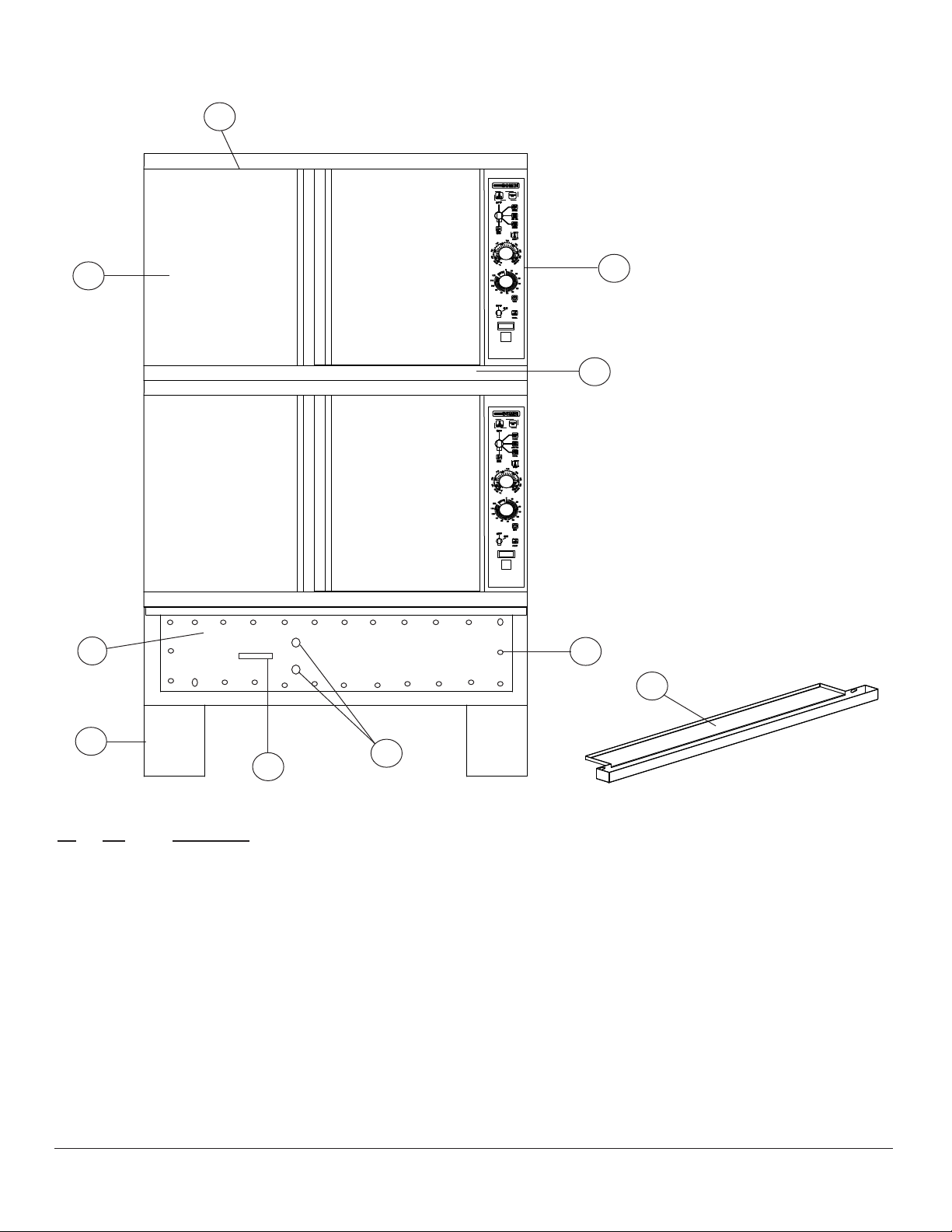
EXTERIOR COMPONENTS
1
2
5
6
7
10
6
11
9
8
Ref. Part
No. No. Description
1 23190 Crown, trim piece, top section s/s
2 R7564 Body side, RH
5 R7046 Control panel w/mp
R7471 Control panel w/o mp
R7566 Handle, control panel
6 R7033 Drip pan
7 R4872 Gasket, cover slide tray (per foot)
8 R7566 Handle, slide tray
9 R9859 Port, deliming
R9577 Spacer, deliming port
10 16384 Screw, cover slide tray
11 R7882 Install base, 18” leg option
R7876 Install base, 14” leg option
R7875 Install base, 8” leg option
R7881 Install base, 6” leg option
R7596 Install base, oor option
FEBRUARY 7, 2014 4 COS-5H & COS-5HB COMBI OVENS
Page 5
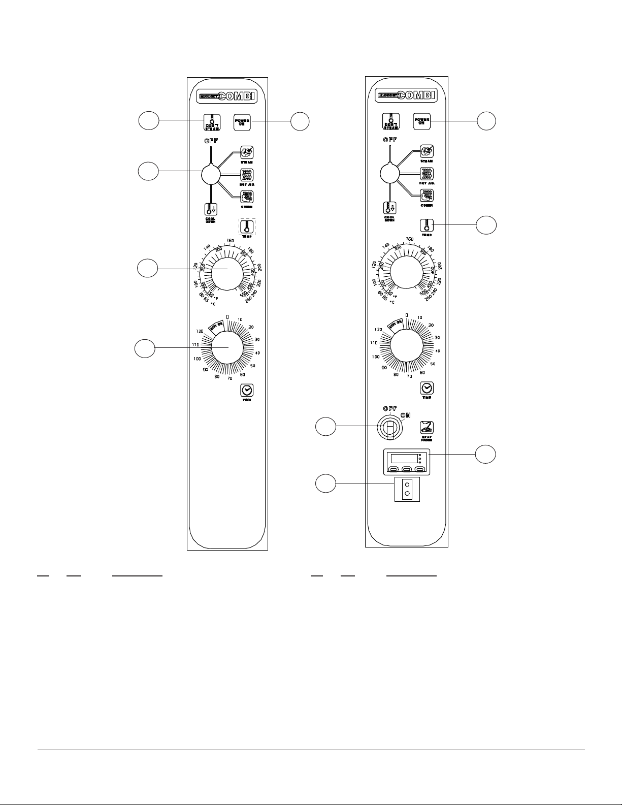
CONTROL PANELS
Without Meat With Meat Probe
1
2
2
4
3
5
6
Ref. Part
No. No. Description
R7450 Decal, standard with out meat probe
R7027 Decal, standard with meat probe
1 R0226 Indicator light, clear “Don’t Steam”
2 R1318 Indicator light, green “Power On”
3 R0226 Indicator light, clear “Temp”
4 R4623 Switch, mode 4 position
R8515 Knob & shaft assy, mode switch
5 R2666 Timer, 120 minute, 230V, 60hz
16686 Knob, timer
6 R6407 Controller kit, hot air, 150-500 degrees P5
R6004 Controller only, hot air,
150-500 degrees
16686 Knob, hot air controller
5805 Screw, machine 6-32x3/8 UNPLT
7
8
9
Ref. Part
No. No. Description
R7319 Probe, thermistor hot air controller
R3992 Gasket, hot air probe
7 R7198 Switch, on/off meat probe
8 R5242 Controller, meat probe
9 R5219 Connector, panel jack, meat probe
10 R5315 Probe, meat plug in type
R5218 Harness, meat probe
R5325 Wire, thermocouple
R6988 Suppressor, arc
R6987 Harness, control panel
R2792 Relay, SPST 240V (not shown)
R7519 Varistor assy, 275V
R9498 Buzzer, 240V
FEBRUARY 7, 2014 5 COS-5H & COS-5HB COMBI OVENS
Page 6
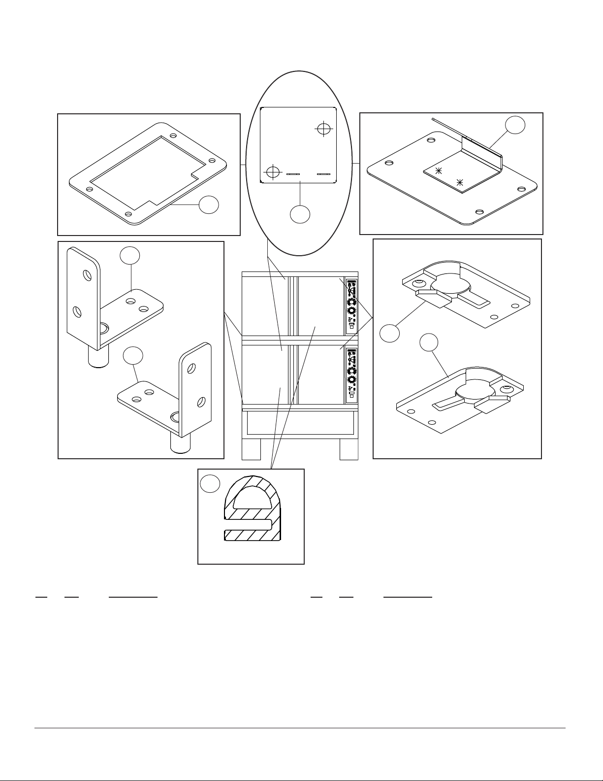
DOOR COMPONENTS
2
3
1
5
7
8
6
4
Cross Section View
Ref. Part
No. No. Description
1 31485 Switch, door proximity
2 R6825 Plate assy, switch
3 R7321 Gasket, door switch
4 R6722 Gasket, door cavity
R3774 Retainer strip, gasket mounting horizontal
R6770 Retainer strip, gasket mounting vertical
5 R6756 Bracket assy, LH Botm
6 R6758 Bracket assy, RH Botm
Ref. Part
No. No. Description
7 R6760 Plate assy, LH Top
8 R6763 Plate assy, RH Top
R7199 Bushing, spacer
R7297 Shim, door catch .03
R7299 Shim, door catch .06
R7748 Spacer, door pivot
15932 Bearing, .627 ID x 3/4 long
FEBRUARY 7, 2014 6 COS-5H & COS-5HB COMBI OVENS
Page 7

DOOR COMPONENTS
LEFT HAND DOORS ONLY
11
3
14
10
13
16
17
8
5
1
15
2
1
12
1
Ref. Part
No. No. Description
6
1
1
1
11
4
1
11
Ref. Part
No. No. Description
1 16384 Screw, machine 10-24 x .5
2 16469 Nameplate, Blodgett
3 R7586 Screw, truss head, 5/16 -18 x 1
4 R7820 Handle assy, LH
5 R2160 Nut, speed
6 R6701 Plate assy, inner door
8 R8414 Insulation
10 R6714 Plate assy, inner door
11 R7589 Screw, truss head, 1/2-20 x .75
12 R8298 Trim assy, window
13 R8819 Gasket, silicone .50 x .13
14 R7037 Bracket assy, LH top
15 R7121 Gasket assy, door center
16 R8304 Glass, window
17 R8421 Gasket, silicone .50 x .18
FEBRUARY 7, 2014 7 COS-5H & COS-5HB COMBI OVENS
Page 8

18
17
DOOR COMPONENTS
RIGHT HAND DOORS ONLY
9
11
3
5
9
2
8
4
14
1
9
7
1
Ref. Part
No. No. Description
1 16384 Screw, machine 10-24 x .5
2 R7586 Screw, truss head 5/16-18 x 1
3 57186 Actuator, proximity switch
4 M3649 Nut, keps 10-24
5 R6701 Plate assy, inner door
7 R6714 Plate assy, inner door
8 R6757 Door bracket assy, RH top
9 R7589 Screw, truss head 1/4-20 x .75
11 R7207 Handle assy, RH welded
14 R7748 Spacer, door pivot
FEBRUARY 7, 2014 8 COS-5H & COS-5HB COMBI OVENS
Page 9

ELECTRICAL COMPONENTS
1
2
3
Ref. Part
No. No. Description
1 R1573 Thermostat, cooking compartment F3
2 R3662 Thermostat, Electrical compartment F7
3 R2801 Thermostat, Too hot to steam P1
23034 Cooling fan, 230V 4” axial
M0571 Guard, cooling fan
R7406 Hose, 3/4” silicone (per inch
4
FEBRUARY 7, 2014 9 COS-5H & COS-5HB COMBI OVENS
Page 10

STEAM SUPPLY COMPONENTS
Steam Supply Assembly Top Section R8418
5
3
3
4
2
Steam Supply Assembly Bottom Section R8419
5
1
2
4
1
5
5
3
5
8
Ref. Part
No. No. Description
1 R6281 Nipple, 3/4 NPT x 1-1/2
2 R6285 Elbow, 3/4 NPT
3 R6290 Elbow, street 3/4 NPT
4 R7255 Valve, 240V 60hz
5 R7360 Fitting, 3/4 x 3/4 NPT barbed
R7406 Hose, 3/4 ID (per foot)
R0254 Clamp, hose 3/4 - 1-1/2”
8 R6780 Quench box assy
R2868 Drain gasket, cavity
FEBRUARY 7, 2014 10 COS-5H & COS-5HB COMBI OVENS
Page 11

MOTOR & HOT AIR ELEMENTS
1
12
13
14
12
5
9
10
Ref. Part
No. No. Description
R5840 Motor & plate assy
1 R4920 Motor, 480V
2 R8154 Bracket, motor mount
3 R8955 Retainer, seal
4 R4244 Seal, motor shaft
5 R8205 Plate, insulation cover
6 20559 Bolt, 3/8-16 x 3/4 hex head
7 M0229 Washer, 3/8 lock
8 R2292 Washer, 3/8 at
11
3
7
8
6
4
2
Ref. Part
No. No. Description
9 R3932 Bolt, 1/4-20 x 1 hex head
10 M0417 Washer, 1/4 lock
11 R0733 Washer, 1/4 at
12 56956 Motor mount gasket
13 R8956 Screw, machine 10-232 x .5 phillips head
14 R0726 Washer, #10 lock
R5769 Tool, motor shaft alignment
39743 Element assy, hot air
R7289 Gasket, element plate
FEBRUARY 7, 2014 11 COS-5H & COS-5HB COMBI OVENS
Page 12

INTERIOR COMPONENTS
1
2
3
4
Ref. Part
No. No. Description
1 R7049 Blower wheel, s/s
R4771 Gasket, blower wheel mounting
2 R7219 Rack holder
3 R3664 Wire rack
4 R7213 Bafe assy
FEBRUARY 7, 2014 12 COS-5H & COS-5HB COMBI OVENS
Page 13

SLIDE TRAY COMPONENTS
CONTACTORS, MOTOR PROTECTORS, TRANSFORMER, TERMINAL BLOCKS
12
10
11
9
3
8
7
Ref. Part
No. No. Description
3 R8093 Probe assy, level sensing
5 R2128 Protector, motor F2
6 51693 Contactor, motor 240V K1
7 R5078 Valve, solenoid
R1270 Screw
R0726 Washer, lock
R8952 Tube, ex 3/8 x 6”
R4160 Fitting, compression union
8 R6566 Contactor, elements
9 23034 Cooling fan
5
6
Ref. Part
No. No. Description
M0571 Guard, cooling fan
10 R2051 Transformer
16384 Screw, #10-24 x 3/8
M1820 Washer, at #10
R7579 Nut, 10-24 w/nylon insert
11 R1586 Terminal block, power
R1580 Stop, end
12 R0048 Connector, 2 screw
R6983 Harness, base to oven
R7566 Handle, base front
FEBRUARY 7, 2014 13 COS-5H & COS-5HB COMBI OVENS
Page 14

SLIDE TRAY COMPONENTS
STEAM GENERATOR & LEVEL PROBE
2
3
4
15
2
6
7
8
9
11
13
17
16
16
Ref. Part
No. No. Description
2 R8093 Level probe assembly
3 R6562 Element, steam
4 R8081 Connector, 1/2” NPT barbed
6 M0231 Nut, hex 1/4 - 20 UNC -28 s/s
7 M0417 Washer, lock 1/4 s/s
8 R0733 Washer, at 1/4 s/s
9 R8092 Washer, 1.0" OD
11 R9445 O-ring, 014 EPDM-70
18 19
Ref. Part
No. No. Description
13 R9444 O’ring, 010 EPDM-70
15 R9601 Deliming bottle assy
16 R8860 Hand pump assy
17 R8861 Bottle, deliming
18 R8875 Clamp, hose
19 R8084 Fitting, male hose, barbed
R9859 Coupling, in line female, deliming port
R9577 Spacer, deliming port
18
19
FEBRUARY 7, 2014 14 COS-5H & COS-5HB COMBI OVENS
Page 15

11
12
SLIDE TRAY COMPONENTS
ELEMENT COVER TRAY ASSEMBLY
6
4
18
9
8
7
14
15
13
2
10
2
Ref. Part
No. No. Description
2 R5305 Timer, 2 second delay
3 R7250 Timer, 3 minute/10 second delay
4 R1443 Steam control, P2 w/potentiometer
R0022 Sensor, P2
6 20785 Screw
7 R5708 Control, water level sensing
Ref. Part
No. No. Description
8 18268 Standoff
9 R2630 Thermostat, boiler high limit F6
11 R2792 Relay
12 6271 Screw
13 20442 Holder, fuse
14 R7532 Fuse, 20 amp solid state
15 R5774 Fuse, 2 amp time delay
18 R7519 MOV assembly
FEBRUARY 7, 2014 15 COS-5H & COS-5HB COMBI OVENS
Page 16

INSTALL BASE COMPONENTS
4
1
3
6
Ref. Part
No. No. Description
1 R7749 Fitting, male 3/4”
3 R9853 Hose, water inlet
4 R7815 Fitting, liquid tight cord
6 5281 Terminal block
4
FEBRUARY 7, 2014 16 COS-5H & COS-5HB COMBI OVENS
Page 17

SCHEMATIC
TOP OVEN SECTION
FEBRUARY 7, 2014 17 COS-5H & COS-5HB COMBI OVENS
Page 18

SCHEMATIC
BOTTOM OVEN SECTION
FEBRUARY 7, 2014 18 COS-5H & COS-5HB COMBI OVENS
Page 19

SCHEMATIC
BASE SECTION
FEBRUARY 7, 2014 19 COS-5H & COS-5HB COMBI OVENS
 Loading...