

Page 1

TMIN
PSIN
COS-5H
INSTALLATION AND OPERATION INSTRUCTIONS
FOR SHIPBOARD USE
FSCM 07695
BLODGETT COMBI
www.blodgett.com
44 Lakeside Avenue, Burlington, Vermont 05401 USA Telephone (800) 331-5842, (802) 860-3700 Fax: (802)864-0183
PN R7354 Rev G (8/02)
E 2002 --- BlodgettCombi
Page 2

TMIN # XXXXXXXXXXXXXXXXXXXXX
SAFETY SUMMARY
Thefollowing aregeneral safetyprecautionsthat are notrelated toanyspecificprocedures
andtherefore donotappear elsewhereinthis publication.Theserecommendprecautions
that personnel must understandand apply during many phases of operation and maintenance.
KEEP AWAY FROM LIVE CIRCUITS
Operating personnel must at all times observe all safety regulations. Do not replacecomponents or make adjustments inside the equipment with the high voltage supply turned
on. Under certain conditions, dangerous potentials may exist when the power control is
in the offposition, dueto thechargeretained incapacitors. To avoid casualties, always remove power and discharge and ground a circuit before touching it.
DO NOT SERVICE OR ADJUST ALONE
Under no circumstances should any person reach into or enter the enclosure for the purpose of servicing or adjusting the equipment except in the presence of someone who is
capable of rendering aid.
RESUSCITATION
Personnel working withor near high voltages should befamiliar with modern methods of
resuscitation.
The following appear in the text of this volume, and are repeated here for emphasis.
WARNING:
Before performing any maintenanceor replacing anycomponent
on this unit, disconnect oven from
electrical source.
Page 3

TMIN # XXXXXXXXXXXXXXXXXXXXX
CHANGE RECORD
CHANGE NO. DATE TITLE/BRIEF DESCRIPTION SIGNATURE OF
VALIDATING OFCR.
Page 4

TMIN # XXXXXXXXXXXXXXXXXXXXX
LIST OF EFFECTIVE PAGES
Insert latest changed pages. Destroy superceded pages.
NOTE:The portion of the text affected by thechanges is indicatedby a vertical line in the
outermarginsofthepage.Changestoillustrationsareindicatedby miniaturepointing hands. Changes to diagrams are indicated by shaded areas.
Dates of issue for original and changed pages are:
Original MARCH 1998...
The total number of pages in this publication are: 29
consisting of the following:
PAGE NO.
CHANGE NO.* PAGE NO. CHANGE NO.*
* Zero in this column indicates an original page
Page 5

TMIN # XXXXXXXXXXXXXXXXXXXXX
APPROVAL AND PROCUREMENT RECORD
APPROVAL DATA FOR: COS-5H
Electric Combination Oven
TITLE OF MANUAL: Technical Manual, COS-5H
Electric Combination Oven
APPROVAL AUTHORITY: Defense General Supply Center
Letter Dated ?? ???
??
CONTRACT NO. NSN NO. OF UNITS APL
REMARKS
DATE: 5 Mar 98
CERTIFICATION:
It is hereby certified that the technical manual provided under contract number XXX-XXX-
XX-X-XXXX for COS-5H has been approved by the approval data shown above.
(Signed) _____________________________
John Bardeau
(Title) VP Sales and Marketing
Blodgett Combi
55 Boyer Circle
Williston, VT 05495
FSCM 07695
Page 6

Table of Contents
Introduction
The Blodgett Combi-Oven/Steamer 2.................................
Description of the Combi-Oven/Steamer 3............................
Oven Features 4...................................................
Installation
General Installation Information 5....................................
Delivery and Location 6.............................................
Installation Base 7.................................................
Utility Connections 9...............................................
Oven Installation --- No Dismantling Required 10........................
Oven Installation --- Some Dismantling Required 11.....................
Oven Dismantling 11.............................................
Oven Re-Assembly 18............................................
Operation
Oven Startup and Shutdown 22.......................................
Optional Meat Probe 23..............................................
Standard Controls 24................................................
Cooking Guide
The Steam Mode 26.................................................
The Hot Air Mode 28................................................
The Combi Mode (Steam and Hot Air) 29..............................
Summary of Functions 30............................................
General Tips and Procedures 31......................................
Suggested Times and Temperatures 32................................
Baked Goods 32.................................................
Eggs 33........................................................
Pork 34.........................................................
Starches 35.....................................................
Beef 36.........................................................
Fish 37.........................................................
Poultry 38.......................................................
Vegetables 39...................................................
Page 7

Table of Contents
Maintenance
Cleaning and Preventive Maintenance 41..............................
Decalcification 42...................................................
Troubleshooting Information 43.......................................
Component Indentification 44........................................
Sequence of Operation 47...........................................
Top Oven Section --- Cool Down 47.................................
Top Oven Section --- Hot Air 47....................................
Top Oven Section --- Steam 48.....................................
Bottom Oven Section --- Cool Down 50.............................
Bottom Oven Section --- Hot Air 50.................................
Bottom Oven Section --- Steam 51.................................
Schematic --- Steam 53..............................................
Schematic --- Hot Air 56..............................................
Schematic --- Cool Down 59..........................................
Schematic --- Base Section 62........................................
Schematic --- Bottom Oven Section 63.................................
Schematic --- Top Oven Section 64....................................
Troubleshooting 65..................................................
Cool Down Mode 65.............................................
Hot Air Mode 66.................................................
Steam Mode 68..................................................
Combi Mode 72.................................................
Wire Harness and Plug Connector Designations 73.....................
Page 8
(Insert Classif. of TMDER Here and At Bottom of Page) CLASSIFICATION:
NAVSEA (USER) TECHNICAL MANUAL DEFICIENCY/EVALUATION REPORT (TMDER)
(NAVSEA S0005--AA--GYD--030/TMMP & NAVSEAINST 4160.3)
Instructions: Insert classification at top and bottom of page. Read the following before completing this
form. Continue on 8½I x11I paper if additional space is needed.
1. USE THIS REPORT TO INDICATE DEFICIENCIES, USER REMARKS, AND RECOMMENDATIONS RELATING TO PUBLICATION
2. BLOCKS MARKED WITH ” * ” ARE TO BE FILLED IN BY THE CONTRACTOR BEFORE PRINTING.
3. FOR UNCLASSIFIED TMDER’S FILL IN YOUR RETURN ADDRESS IN SPACE PROVIDED ON THE BACK. FOLD AND TAPE WHERE
INDICATED AND MAIL. (SEE OPNAVINST 5510.1E FOR MAILING CLASSIFIED TMDERS.)
4. FOR ADDITIONAL INFORMATION, CALL AUTOVON 360---4809---9084 OR COMMERCIAL 905---882---5064
1. NAVSEA NO. * 2. VOL.
4. REV DATEOR TM CH.
DATE
A. EXCELLENT B. GOOD C. FAIR D. POOR E. COM PLETE F. INCOMPLETE
8. GENER ALCOMMENTS
PAGE
NO.
PARA
GRAPH
A.
LINE
FIG.
NO.
B.
NO.
C.
D.
PART *
5. SYSTEM/EQUIPMENT 6. IDENTIFICATION/NOMENCLATURE (MK/MOD/AN)
7. USERS EVALUATIONOF MANUAL (CHECK APPROPRIATEBLOCKS)
9. RECOMMENDED CHANGESTO PUBLICATION
TABLE
E.
3. TITLE *
F. RECOMMENDED CHANGES AND REASONS
10. ORIGINATOR AND WORK CENTER
13. SIGNATURE OF WORK CENTER HEAD 14. SIGNATURE OF DEPARTMENT OFFICER 15. AUTOVON/COMM
16. SHIP HULL NO. AND/OR STATION ADDRESS (DO NOT ABBREVIATE)
A.CONTROLNO. B.COGISEA C.DATE D.PRIORITY E.TRANSMITTEDTO
NAVSEA 9066/10 (REV. 6.85) S/N 0116---LF---090---9651
(REPLACES 4---84 EDITION & NAVSEA 4160/1--DESTROY STOCK)
(PRINT)
11. ORIGINATOR’S RANK, RATE OR GRADE,AND TITLE 12. DATE SIGNED
NO.
17. THIS SPACE ONLY FOR NSDSA
RECEIVED FORWARDED DUE
CLASSIFICATION:
Page 9

PLEASE CLOSE WITH TAPE --- DO NOT STAPLE --- THANK YOU
FOLD HERE
COMMANDING OFFICER
NAVAL SHIP WEAPON SYSTEMS ENGINEERING STATION
NAVAL SEA DATA SUPPORT ACTIVITY (CODE 5B00)
PORT HUENEME, CA 93043--5007
FOLD HERE
Page 10

IMPORTANT
WARNING: IMPROPER INSTALLATION, ADJUSTMENT,
ALTERATION, SERVICE OR MAINTENANCE CAN CAUSE
PROPERTY DAM A GE, INJU RY OR DEATH. READ THE INSTALLATION, OPERATING AND MAINTENANCE INSTRUCTIONS THOROUGHLY BEFORE INSTALLING OR
SERVICING THIS EQUIPMENT
FORYOURSAFETY
Do not store or use gasoline or other flammable vapors or
liquids in the vicinity of this or any other appliance.
The informationcontained in this manual is important for the proper
installation, use, and maintenance of this oven. Adherence to these
procedures and instructionswill result in satisfactory baking results
and long,trouble free service. Please read this manual carefully and
retain it for future reference.
Errors: Descriptive, typographic or pictorialerrors are subject to correc-
tion. Specifications are subject to change without notice.
Page 11

APERSONALWORD
FROM BLODGETT COMBI
Congratulations on your purchase of the BLODGETT Combi-Oven/Steamer.
We firmly believe that your choice hasbeen a wise one, and trust you will receive many years of excellent service from your new multi-purpose oven.
The Combi-Oven/Steamerconcept offers completely new potential for cooking which minimizes shrinkage, while maintaining food’s essential vitamins
and valuable nutrients. In addition, you will find that cookingwith the CombiOven/Steamerwillsavetime, laborandextensive cleaningof boththekitchen
and the appliance.
With the Combi-Oven/Steamerthe quality, taste, consistency, andlook of the
foodare improved,thusendorsing thepolicytowhichwe’vealways adhered:
“For Better Cooking!”
Onceyou’vehad achance touseyourmulti-purposeoven,pleasetellus, your
dealer and colleagues about any creative and interesting applications you
have discovered; exchange ideas with other users. Be sure to advise us or
yourdealerimmediatelyshouldany mechanicalortechnical problemsbeencountered (...we’re here to help!) and above all “Enjoy Cooking the
BLODGETT Combi- Oven/Steamer Way!
Page 12

Your Service Agency’s Address:
Model:
Serial Number:
Your oven was installed by:
Your oven’s installation was checked by:
Page 13
Introduction
The Blodgett Combi-Oven/Steamer
For quite some time, commercial cooking equipment has remained more or less unchanged.
There are kettles, deck ovens,thegoodoldrange
with its legion of pots and many other extra
appliances. The result: time expenditure, excessive manual work, and countless cleaning processes.The lastfewyearshavepavedthew ay for
a revolutionin the equipment of restaurant and institutional kitchens.
The Blodgett Combi-Oven/Steamer offers a completely new method of cooking. With the Oven/
Steameryou have thechoiceof twocookingpro -
cesses: Steam and Hot Air, either...
D
Separately
D
Combined, or
D
In Sequence
And for easy operationyoucan choose from three
modes:
Steam Hot Air
Combi
Steam &
Hot Air
In the Steam mode you can:
steam reheat reconstitute
stew thaw simmer
blanch preserve braise
poach
In the Hot Air mode you can
roast bake
grill gratinate
broil
IntheCombinationSteamand HotAirmodeyou
can:
defrost roast rethermalize
reheat bake forced steaming
Not only that, youcan use two or three functions
in sequence during one cooking process. Wecall
this:
D
combi-steaming
D
combi-roasting
D
combi-baking
The combination of circulating hot air and steam
in the space saving, high performance CombiOven/Steamer leads to improvements in the following areas:
D
increased productivity in the kitchen
D
a reduction in capital expenditures for multiple
equipment replacement
D
a wider range of menu choices
D
a simplified cleaning process
The work process issimplified since products are
prepared on or in steam table pans and trays.
Foodcanbe cooked,stored,andtransportedwith
the same pans. Small amounts of product can be
processed efficiently; pre-cooked and convenience foods can be reheated within minutes.
Many frozen foods can be processed withoutprethawing. This flexibility in preparation reduces the
needforkettles and steam tablessincethere is no
needforlargeamounts offoodtobekeptwa rm for
long periods of time.
Todaytheimprovement of food qualityis moreimportant than ever. Vegetables are cooked in the
Blodgett Combi-Oven/Steamer without water at
the optimal temperature of just under
212_F/100_C, maintainingvaluablevitamins, minerals,nutrients and traceelements.Cookingmeat
intheCombiresultsinlessshrinkageandafirmer,
juicier product.The BlodgettCombi-Oven/Steamerisbeing used more and more for baking.Steam
andHotAirmodesmake itageneralpurposebaking appliance.
2
Page 14

Introduction
Description of the Combi-Oven/Steamer
ABOUT THE OVEN/STEAMER
Blodgett Combi-Oven/Steamers are quality produced using high-grade stainless steel w ith first
class workmanship.
The high performance fresh ste amgeneratorwith
its controlsystem makes it possible toenjoy allof
the advantages of a high quality steamer at the
flickof a switch. Fresh steam entersthe ovencavity without pressure and is circulated at high
speed. This process enables quick and gentle
cooking and ensures high quality food while providing convenient working methods. The steam
generator is completely automatic and protected
from running dry.
The exhaust system is effective in all cooking
modes and results in better quality foods and no
flavortransfer. The fan, which is guardedagainst
accidental finger contact, is driven by a quiet and
powerful motor. Thecondenser draws out excess
steam from the appliance. Condensation and
waste water, which result during steaming and
cleaning, are continuously drained.
The use ofhigh qualityinsulationimpedes excessive heat radiation and saves energy.
OVEN/STEAMER OPERATION
Ease of operation is guaranteed through the simplearrangementofthecontrols.Graphicsymbols
make the appliance easy for even inexperienced
kitchenstaff tooperate.Steam, HotAirand Combi
modes can be selected with one s witch. A fourth
function on the mode selection switch, the Cool
Down mode, allows the oven cavity to cool down
rapidly with the door opened or closed.
Cleaning is kept to a minimum. The interior is
sprayed with a self-acting cleaning solution which
interacts with steam to easily remove crusts and
stains. The oven is designed for easy care and is
welded water tight so that the internal cooking
cavity may be rinsed with a hose after the steam
cleaning process.
3
Page 15
Introduction
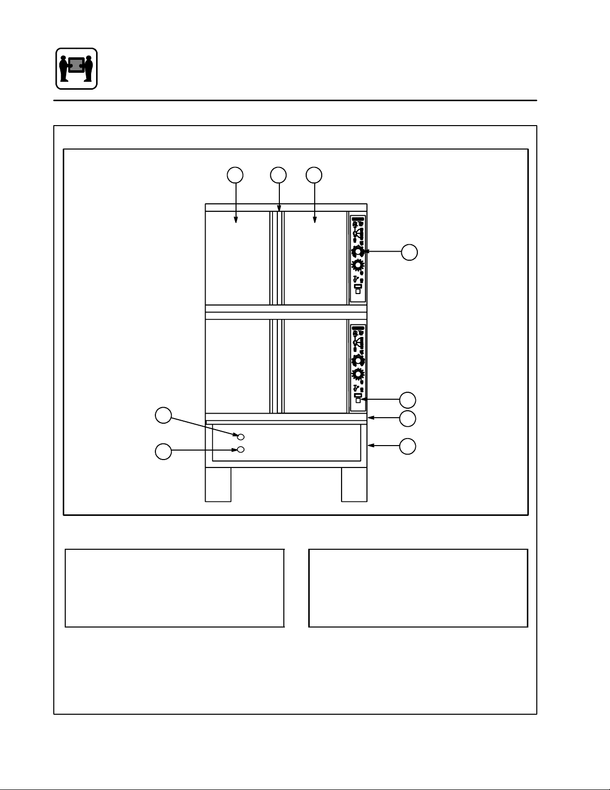
Oven Features
2 23
5
6
Standard Features
1
7
8
4
Control Panel
1
2 Oven Doors
3 Rotating Door Latch
4 Base Section
Figure 1
5 Deliming Inlet
6 Boiler Drain
7 Optional Meat Probe
8 Door Drip Pan
4
Page 16
Installation
General Installation Information
The purpose of the installation section of this
manual is to assist the designers and naval architects engineering the installation of a Blodgett
CombiCOS-5HHatchableCombinationOveninto
a new or existing ship.
Blodgett Combi has developed the COS -5H to fit
inthe same footprint asa BlodgettMark V convectionOven.The COS-5H Combinationoven can be
used as aconvection oven, steamer,orin a“Combi” mode in which pulsed steam is combined with
convection to provide faster cooking andincrease
the moisturecontent of cookedfoods.Because of
these features, the ovenutilizeswater for generating steam. The Combi is a multi-system cooking
oven and is more complex than a convectional
oven. Therefore, moreattention has to be paid to
the installation process t han that of a convection
oven.
The COS-5H requires the following support systems:
D
Power 440VAC,3phase,60ampservice
D
Water Potable, 40 to 50 psi
D
Drain Atmospheric vented drain,
1” minimum diameter
D
Hood Air venting required for steam
removal
THE INSTALLATION INSTRUCTIONS CONTAINED HEREIN ARE FOR THE USE OF QUALIFIEDINSTALLATIONAND SERVICEPERSONNEL
ONLY. INSTALLATION OR SERVICE BY OTHER
THAN QUALIFIED PERSONNEL MAY RESULT IN
DAMAGE TO THE OVEN AND/OR INJURY TO
THE OPERATOR.
Qualified installation personnel are individuals, a
firm, a corporation, or a company which either in
person or through a representative are engaged
in, and are responsible for:
D
Theinstallationofelectricalwiringfromtheelectric meter, main control box or service outlet to
the electric appliance.
Qualified installation personnel must be experiencedinsuchwork,befamiliarwithallprecautions required and have complied with allrequirements of state or local authorities having
jurisdiction.
Reference: National Electrical Code, ANSI/NFPA
70---Latest Edition and/or Canadian Electrical
Code CSA C22.1 as applicable.
This equipment is to be installed in compliance
withtheBasicPlumbing Code of theBuildingOffi -
cials and Code Administrators International Inc.
(BOCA) and theFood Service Sanitation Manual of
the Food and Drug Administration (FDA).
5
Page 17

Installation
Delivery and Location
DELIVERY AND LOCATION
The COS-5H hatchable combination oven is
shipped fullyassembled on a special vibration resistant pallet. In addition, the oven is mounted on
two hardwood skidsto facilitate removal from the
pallet. These skids were designed to match the
height of the separate installation base. This allows the assembled oven to be slid directly onto
the base after the installation base is mounted in
positionandhardplumbedwithpotable waterand
electric power.
COS-5H dimensions:
Height 62.25” with legs
68.25” with 6” legs
64.75” with base
Width 38.12”
Depth 43”
The following clearances are required for the
COS-5H:
Sides 0”
Rear 6”
UNPACKING
1. Removetheprotectivecoveraroundthe oven.
Inspect the unit for visible damage.
2. Remove the bolts that lock the 2-1/2” x 4”
hardwood skids to t he pallet base.
3. Useaforklifttoraisetheovenassemblyoff the
pallet.Theskidscanbeleftinpositiontoassist
in moving an assembled oven onto the installationbaseordiscardedafterthe ovenassembly is unbolted into separate components for
passage through hatches.
ASSISTANCE
Blodgett Combi also provides engineering assistance when custom installation kits are required.
Our goal is to ensure that each oven installation
can be made inthe most efficient and economical
manner.
For further information, please contact the Blodgett Combi Engineering Department:
D
Phone 802-860-3708
D
Fax 802-860-3784
D
Email wgoldm@maytag.com
6
Page 18
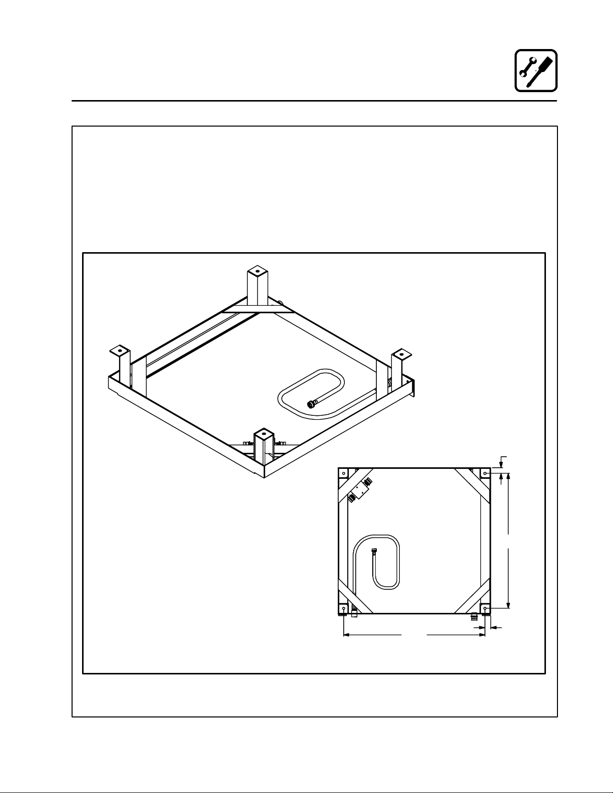
Installation
Installation Base
The Blodgett Combi COS-5H utilizes a stainless
steel locking installation base. The base is availablewithorwithoutlegs. Theinstallationbase was
designed to facilitate the installation process and
toimprovethe accesstotheoven ifandwhenmajor service is required.
Since the COS-5H is slightly narrower than the
installation base, multiple bases can be installed
sideby sideon thedeckwith noallowanceforside
clearance.
1. Secure the 2-1/2”high installation base using
one of the following methods:
2. Weldthebasedirectlytothedeck.
3. Boltthebasetothedeck.
4. Seal the base with an NSF approved sealant.
Base S hown Upside Down
INSTALLATION BASE WITH LEGS
Figure 2
BOTTOM VIEW
35.50
1.44
33.91
1.44
7
Page 19
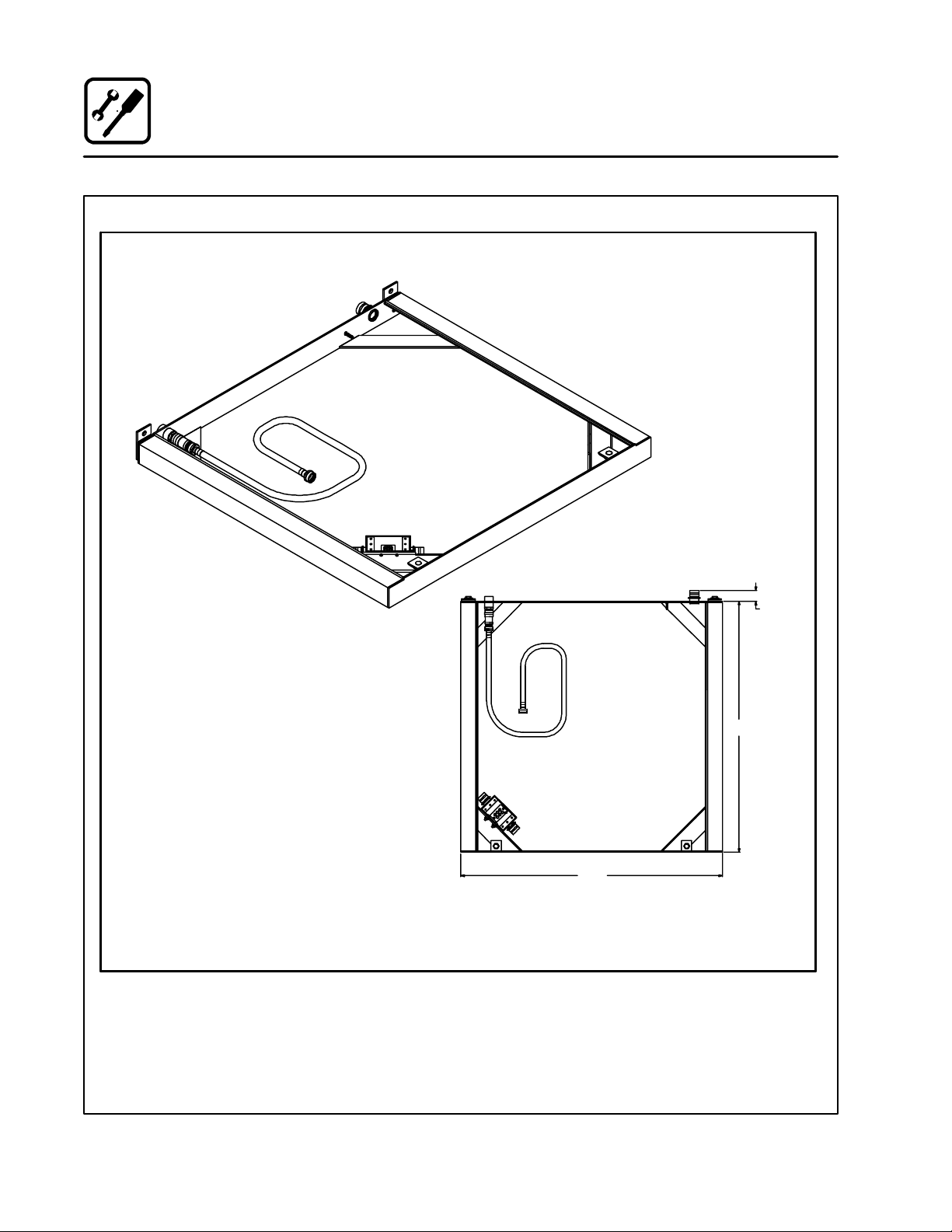
Installation
Installation Base
INSTALLATION BASE
Figure 3
1.56
36.78
38.37
8
Page 20
Installation
Utility Connections
WATER CONNECTION
The oven requires access to potablewater with a
pressure of approximately 40 to 50 PSI.
1. The wateris connectedtotherearof theinstallation base at the 3/4” NPT female coupling.
2. The water is directed to the oven through an
in-line pressure regulator and a flexible internalhose whichconnectsto a fittingin thefront
of the oven.
ELECTRICAL CONNECTION
The power requirement of the oven is 440 volt, 3
phase, 60 amp service.
1. The electrical service is brought into the oven
through the seal tight connector located on
therearoftheinstallationbase.
2. The power leads are brought into a splash
proof terminal box located in the front of the
installation base.
3. A grounding stud is supplied on the inside of
the installation base. See Figure 5.
Figure 4
DRAIN CONNECTION
Anopendrain systemutilizingafixedfunnelisrecommended. For multiple oven installations, install
a deck mounted sloping drain with individualfunnels positioned to accept the drain outlets of the
individual ovens.
Figure 5
9
Page 21
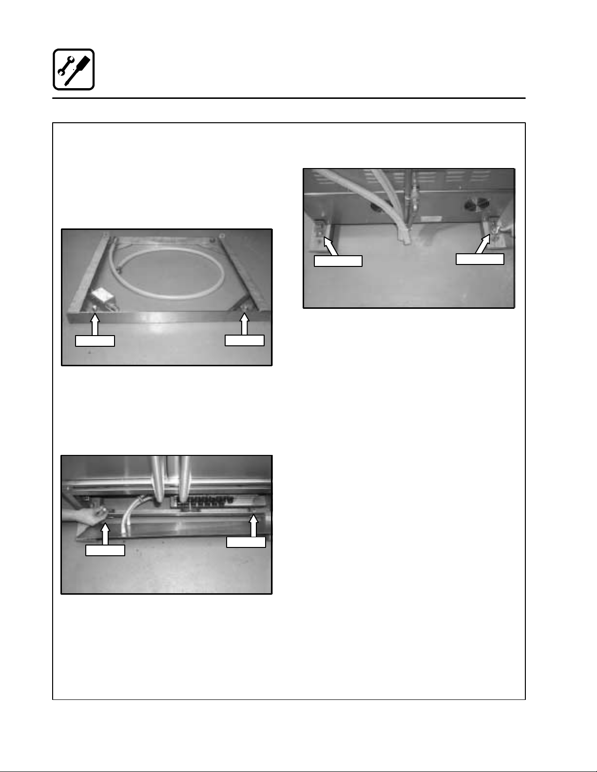
Installation
Oven Installation --- No Dismantling Required
Use this procedure if the ovenassemblydoesnot
have to be dismantled to bring it into the galley
where the installation base has been fitted.
1. Slidetheovenassembly onthe shippingskids
in front of the installation base.
2. Remove the two1/2”bolts fromthefront ofthe
installation base. See Figure 6.
1/2” Bolt
1/2” Bolt
Figure 6
3. Unscrew the front panel from the oven base
section. Leave the hoses connected to the
front panel and the oven base section.
4. Removethetwoboltssecuringthe skidstothe
front of the oven base section. See Figure 7.
1/2” Bolt
1/2” Bolt
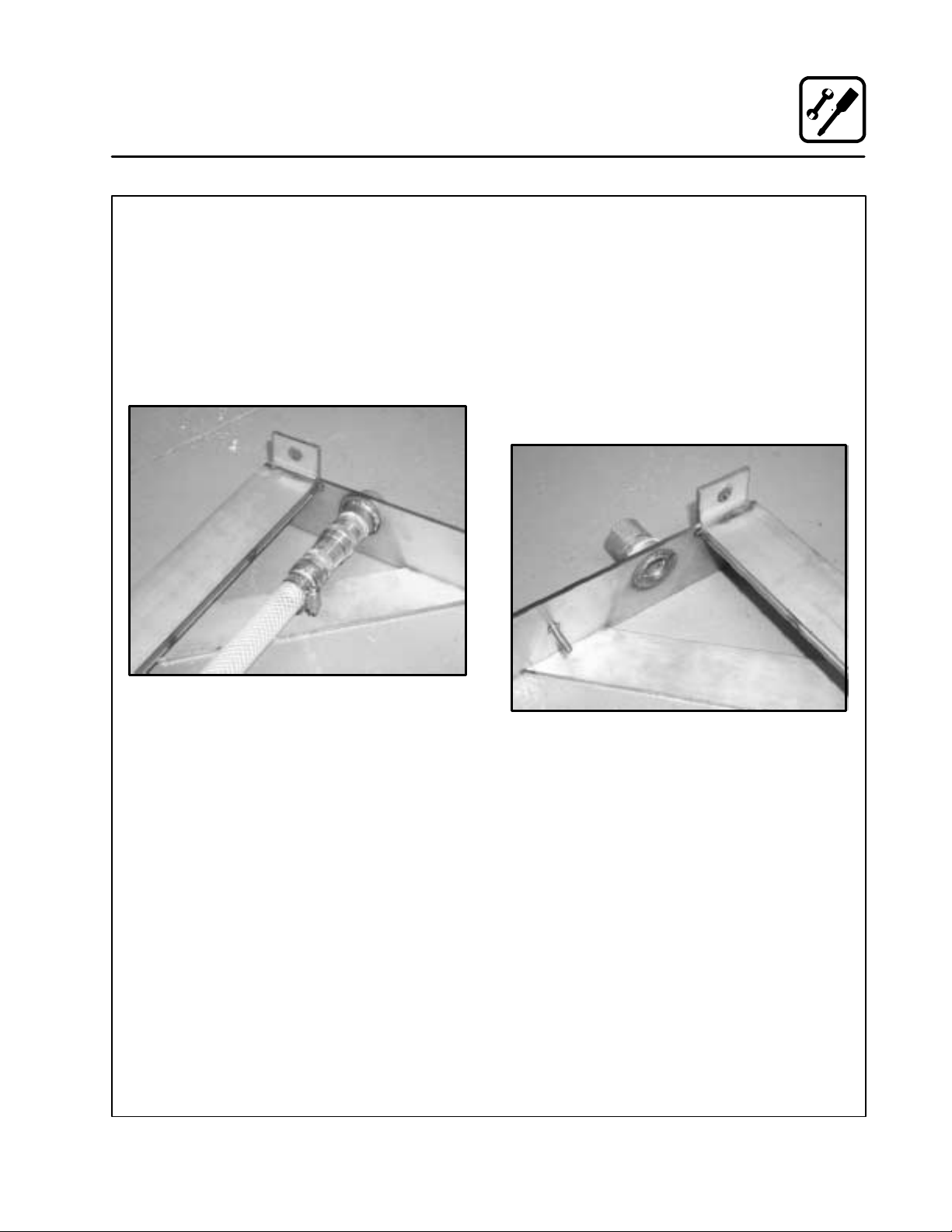
5. Removethetwoboltsandangleplatessecuring
the skids to the rear of the oven base section.
Bolt & Plate
Bolt & Plate
Figure 8
6. Move the oven assembly to the installation
base as follows:
1. Lubricate the top surface of the installa-
tion base with a little grease or silicone
spray.
2. Slide theovenassemblyoffthe skidsonto
the tracks of the installation base.
3. The locking pins on the rear of the oven
base section will fit into and lock the base
tothe uprighttabsattached tothe installation base.
4. Reinstall the two bolts that were removed in
Step 2, from the installation base through the
oven base section into the installation base.
SeeFigure7forinstallationlocation.
5. Hookup waterand electric alconnections to the
oven base section. Apply NSF approved sealant to the cover of the splash proof terminal
box.
Figure 7
10
Page 22
Installation
Oven Installation --- Some Dismantling Required
Use this procedure if the oven a ssembly will be
dismantled to bring it into the galley where the
installation base has been fitted.
The assembled oven consists of three sections:
D
upper oven section
D
lower oven section
D
oven base section.
The oven base section consists of the majorelectrical components, steam generator, and the attachment components for mating the oven assembly to the installation base which is mounted
directlyto the deck. In order todismantle the oven
assembly, youwillhave to separate electricalwire
harnesses and plumbing lines. We recommend
that you tape both sides of each electrical and
hose connection and mark them for easy identification during reassembly.
Ifyouareinstallingmore than one ovenassembly,
keepallhardwareandpanels associated withone
oven assembly separate from the other oven assemblies. If the oven assembly has to be dismantledin orderto fitthrough thehatches, usethe
following procedure:
OVEN DISMANTLING
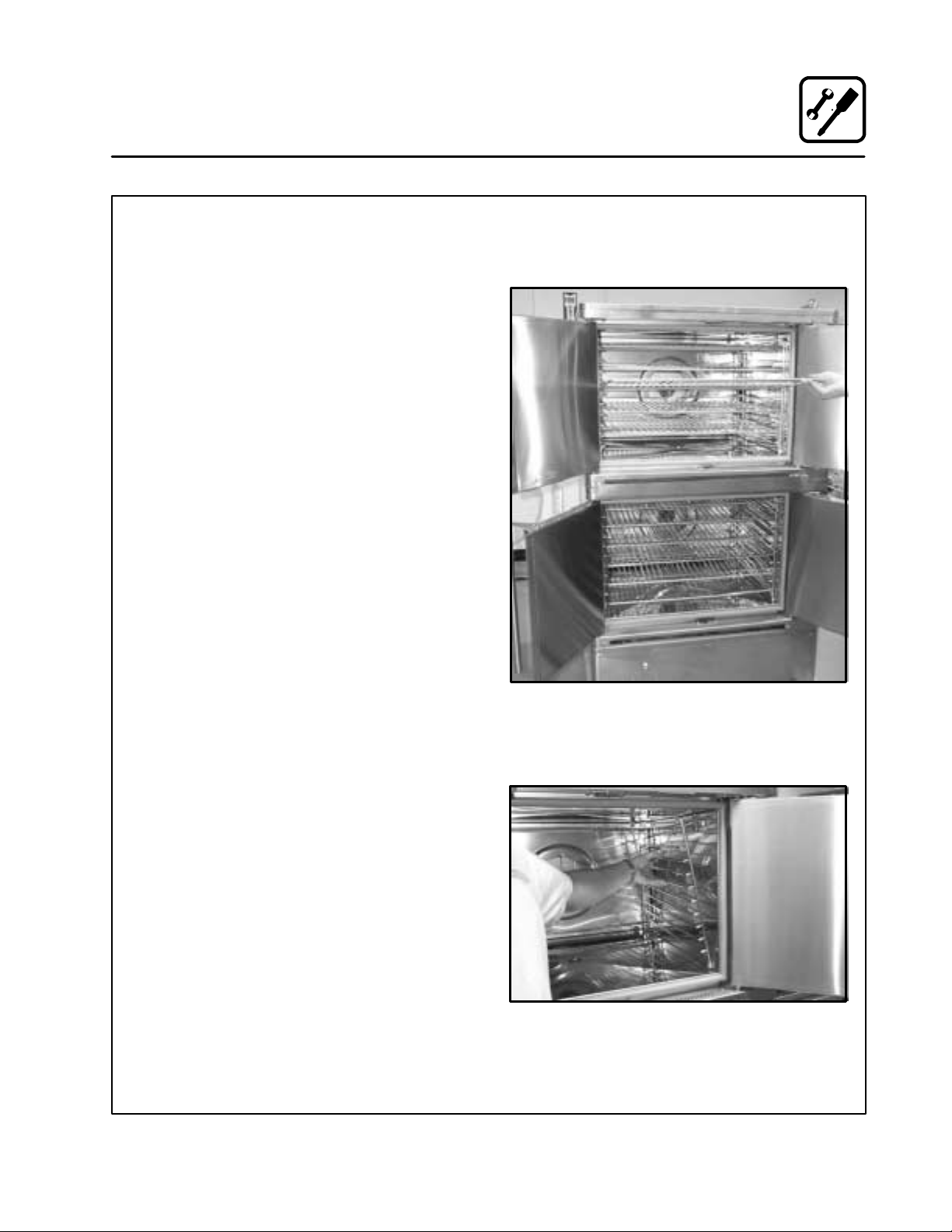
1. Remove the racks fromthe inside of both the
upper and lower oven sections. See Figure 9.
Figure 9
2. Remove the side support racks from the in-
side of both the upper and lower oven sections.SeeFigure10.
Figure 10
11
Page 23
Installation
Oven Installation --- Some Dismantling Required
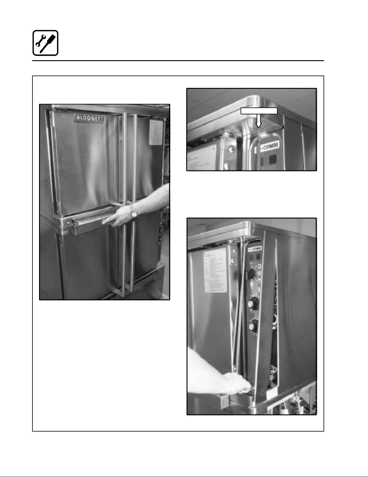
3. Remove the drip pan from the front of both
ovens.SeeFigure11.
5. Remove the control panel coverby liftingand
pulling the “D” handle toward you about 6”.
See Figure 13. Do this to both the upperoven
and the lower oven.
Remove Screw
Figure 12
Figure 11
4. Remove the locking tab plate above the control panelby removing the Phillips screw. See
Figure 12. Dothis toboth the upper ovenand
the lower oven.
Figure 13
12
Page 24
Installation
Oven Installation --- Some Dismantling Required
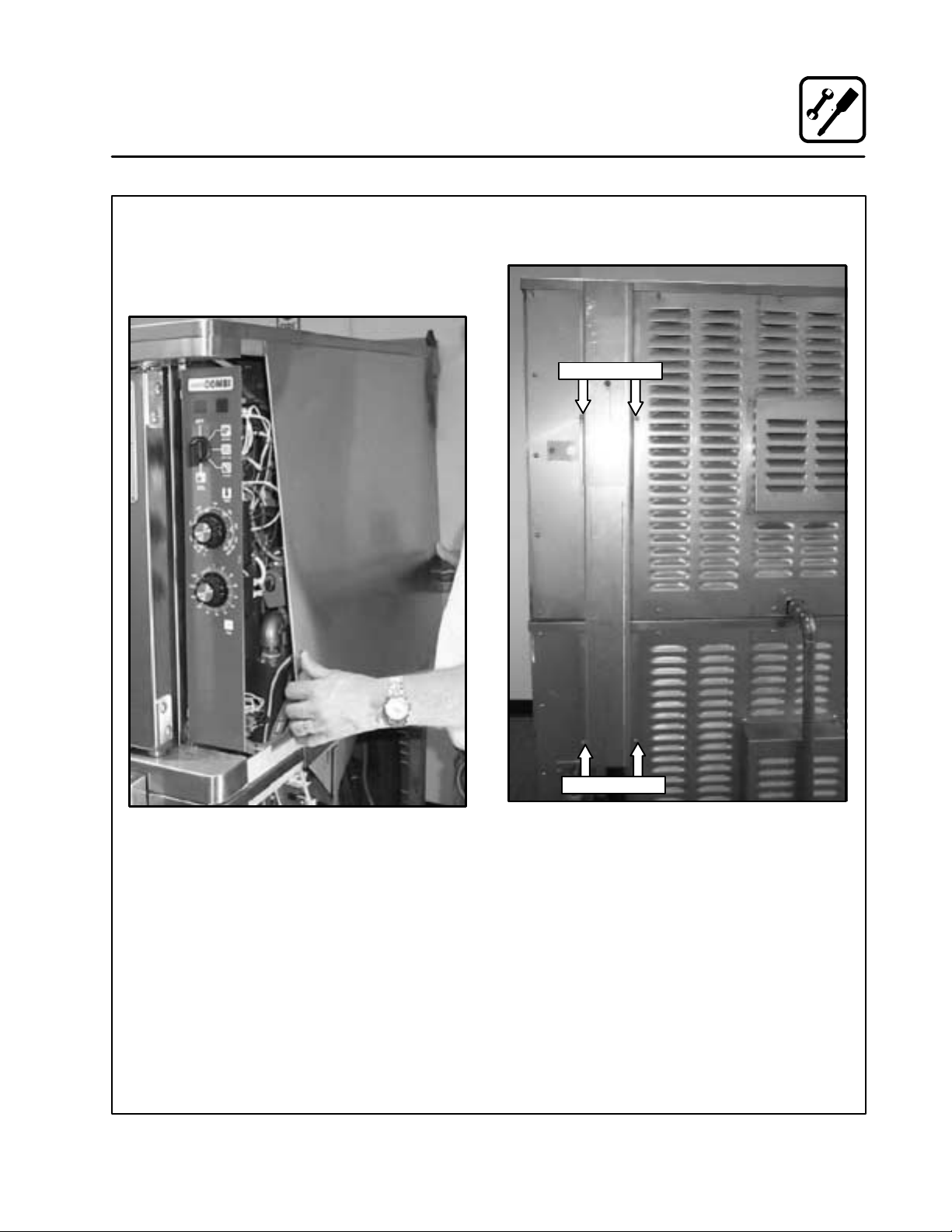
6. Remove the right side rear panel by sliding it
forwardaboutaninchand then liftingtheentire panel to free the retaining springs. See
Figure 14. Dothis toboth the upper ovenand
the lower oven.
7. Remove thefourscrews holdingtherearverticalductontherearofthe oven.SeeFigure 15.
Remove Screws
Figure 14
Remove Screws
Figure 15
13
Page 25
Installation
Oven Installation --- Some Dismantling Required
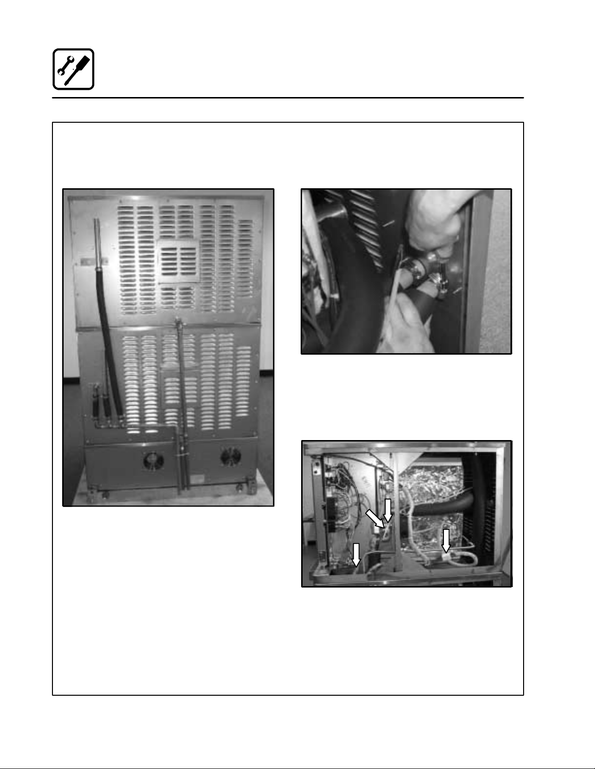
8. Cut the wiretieholdingthecopperdraintubes
together. Remove the fiverubber drain hoses
fromtheupperandlowersections.See
Figure 16.
9. Disconnect the two orange hoses from the fitting on the rear body panel. See Figure 17.
Both of these hoses have black foam insulation on them.
Figure 17
10. Disconnect the electrical wire harnesses (J1,
J3, J7, and J8) that connect the upper oven
section to the oven base section. See
Figure 18. Mark connections prior to disconnecting for ease of re-assembly.
Figure 16
Figure 18
14
Page 26
Installation
Oven Installation --- Some Dismantling Required
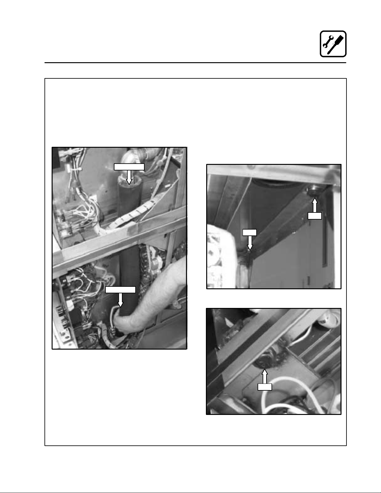
11. Disconnect and remove the steam line to the
upper oven section at locations shown in
Figure 19. Thetop of the hoseis securedwith
a band clamp. The bottom of the hose pulls
out of the boilerin the oven base section. This
orangehose hasablackfoaminsulatedcover
around it. Remove hose with insulation from
oven assembly.
Disconnect
13. Remove the three bolts (1/2 inch diameter)
that connect the top and lower oven sections
together.
Two boltsarelocatedinthe rear upperleftand
right corners of the lower oven section. These
bolts can be accessed from the back of the
lower oven section. See Figure 20.
The third bolt is accessed from the right side
of the lower oven section. It is located in the
upper right hand corner. See Figure 21.
Bolt
Bolt
Disconnect
Figure 19
12. Removetherearbodypanelontheloweroven
section.
Figure 20
Bolt
Figure 21
15
Page 27

Installation
Oven Installation --- Some Dismantling Required
14. Removetheupperovensection from atopthe
lower oven section. Use care not to chafeany
ofthe harnesses thatcome fromthe basesection. Use gloves to protect hands from any
sharp edges.
15. Disconnect the electrical wire harnesses (J2,
J4, J5, and J6) that connect the lower oven
section to the oven base section. See
Figure 22. Mark connections prior to disconnecting for ease of re-assembly.
Figure 22
16. Disconnect and remove the steam line to the
lower ovensection. See Figure 23. The top of
thehoseissecuredwithabandclamp.The
bottomof thehosepulls outof the boilerinthe
oven base section. This orange hose has a
black foam insulated cover around it (shown
with blackfoaminsulation removed).Remove
hose with insulation from oven assembly.
16
Figure 23
Page 28

Oven Installation --- Some Dismantling Required
17. Seal the outlets of the steam generator in the
oven base section with the plastic caps provided with the installation kit. The caps will
prevent water from splashing over the electrical equipment as the oven base section is
tipped on it’s side when passing through a
hatch.SeeFigure24.Theovenbasesection
shouldbe tipped onto it’s left side forpassing
through a hatch.
Installation
Figure 25
Figure 24
18.Removetherearbodypanelfromtheoven
base section. Unscrew the front panel from
the oven base section. Leave the hoses connected to the front panel and the oven base
section.
19. Removethefourbolts(1/2inchdiameter)that
connectthelowerovensectionandovenbase
section together.
T wo bolts are located in the rear upper left and
right corners of the oven base section. These
bolts can be accessed from the back of the oven
base section. See Figure 25 and Figure 26.
The third bolt is accessed from the right side
oftheovenbasesection. Itislocatedintheupper front right hand corner. See Figure 27.
The fourth bolt is accessed from the left side
oftheovenbasesection. Itislocatedintheupper front left hand corner. See Figure 28.
20. Removethe lower oven section from atop the
oven base section. Use care not to chafe any
ofthe harnesses thatcome fromthe basesection. Use gloves to protect hands from any
sharp edges.
Figure 26
Figure 27
17
Figure 28
Page 29

Installation
Oven Installation --- Some Dismantling Required
OVEN RE-ASSEMBLY
After the installation base is secured in position,
connected to potable water and electrical power,
the oven sections may be assembled onto it. In
galleyswhere ovens are located next toeachother, the ovensectionsshouldbe assembledpriorto
sliding the oven assemblyintothe final positionon
the installation base.
1. Remove the two1/2”bolts fromthefront ofthe
installation base. See Figure 29.
1/2” Bolt
Figure 29
1/2” Bolt
4. Install the four bolts (1/2 inch diameter) that
connectthelowerovensectionandovenbase
section together.
Two nuts are located in the rear lower left and
right corners of the lower oven section. These
nuts can beaccessedfromthe back oftheoven
base section. See Figure 25 and Figure 26 on
page 17.
Thethirdnut isaccessedfrom the right sideof
theoven basesection. Itis locatedinthelower
front right hand corner of the lower oven section. See Figure 27 on page 17.
The fourthnutisaccessed from theleft side of
theoven basesection. Itis locatedinthelower
frontlefthandcornerofthelowerovensection. See Figure 28 on page 17.
5. Remove the two plastic caps that were inserted onto the steam generator.
2. Lubricate the top surface of the installation
basewithalittlegreaseorsiliconespray.Position the oven base section onto the flat track
surface of theinstallation base approximately
4” to 5”. Support the front of the oven base
section with a piece of 2” pipe (2-3/8” OD
approximately) by 39” (minimum) long.
3. Apply a 1/8 inch bead of clear silicone RTV to
theperimeterofthetop edge oftheovenbase
section. Lift the lower oven section onto the
oven base section. Use gloves to protect
hands from any sharp edges.
Figure 30
18
Page 30

Installation
Oven Installation --- Some Dismantling Required
6. Installandreconnectthesteam linetothelower
oven section. See Figure 31. Secure the top of
the hose with a band clamp. Insert the bottom
of the hosein the fitting on the steam generator
intheovenbasesection.Thisorangehosehas
a black foam insulated cover around it (shown
with black foam insulation removed).
9. Apply a 1/8 inch bead of clear silicone RTV to
theperimeterofthetop edgeoftheloweroven
section. Lift the upper oven section onto the
lower oven section. Use gloves to protect
hands from any sharp edges.
10. Install the three bolts (1/2 inch diameter) that
connect the top and lower oven sections together.
Two nutsare located in the rearlower left and
right corners of the upperoven section.These
nuts can be accessed from the back of the
lower oven section. See Figure 33.
Thethirdnut isaccessedfrom the rightsideof
the lower ovensection. It is located in the upper front right hand corner of the upper oven
section. See Figure 34.
Bolt
Bolt
Figure 31
7. Reconnect the electrical wire harnesses (J2,
J4, J5, and J6) that connect the lower oven
section to the oven base section.
Figure 32
8. Install the rear body panel on the oven base
section.
Figure 33
Bolt
Figure 34
19
Page 31

Installation
Oven Installation --- Some Dismantling Required
11. Install the rear body panel on the lower oven
section.
12. Installandreconnectthesteam linetotheupper oven section at locations shown in
Figure 35. Secure the top of the hose with a
band clamp. Insert the bottom of the hose in
the fittingon the steam generator in the oven
base section. This orange hose has a black
foam insulated cover around it.
Reconnect
13. Reconnectt h ree electricalwireharnesses(J1,
J3, J7, and J8) that connect the upper oven
section to the oven base section.
Figure 36
14. Reconnect the two orange hoses onto the fittingsonthelowerrearbodypanel.Assurethat
the foam insulation is also reinstalled.
Reconnect
Figure 35
Figure 37
20
Page 32

Installation
Oven Installation --- Some Dismantling Required
15. Reconnect the five rubber hoses to the upper
and lower sections. Wire tie the three copper
drain tubes together at location shown in
Figure 38.
20. Slide the oven assembly back ontothe installation base.The lockingpinson the rear ofthe
ovenbasesectionwill fitintoandlockthebase
to the upright tabs attached to the installation
base. Install the two bolts (1/2 inchdiameter)
removed in STEP1 (Figure 29), thru the oven
base sectionand into the installationbase. In sure that the drains from the upper and lower
ovens and the orange hose and black hoses
from the P2 stack tubes are located over the
floor drain.
21. Hook up water and electrical connections to
oven base section. ApplyNSF approved sealant to cover of splash proof terminal box.
INSTALLATION COMPLETE. PROCEED WITH
CHECK-OUT PROCEDURE.
Reinstall Screws
Wire Tie
Figure 38
16. Reinstall the rear vertical duct to the rear of the
oven stack with four screws. See Figure 39.
17. Review instructions in STEPS 1 thru 16 to ensure that allconnections havebeenmadeproperly, hoses are not kinked, andallelectricalwire
harnesses are routed correctly to prevent chafe
or damage.
18. Complete the attached checklist document.
19. Replaceoven electricalcontrol panels on both
upperandlower ovensections. SeeFigure 13
and Figure 14.
Reinstall Screws
Figure 39
21
Page 33

Operation
Oven Startup a nd Shutdown
OVEN START-UP
1. Turnthemodeswitchtothedesiredmode,
Steam, Hot Air, Combi, Cool Down.
STEAM MODE
1. Turn the mode switch selector knob to the
Steam Position. The green “POWER” indicatorlampilluminates on thefrontcontrolpanel.
2. Steam fills the cavity and is controlled by a
non-accessible internal thermostat.
Preheating for the STEAM mode
Before the first use of the appliance, daily or after
the oven has been idle for 3 hours, preheat with
the STEAM function until steam enters the oven
cavity. The appliance can then be loaded.
HOT AIR MODE
1. Turn the mode selector switch to the Hot Air
position. The green “POWER” indicator lamp
illuminates on the front control panel.
2. Set theHot Air thermostat to the desired temperature. The Thermostat lamp illuminates indicating the cavity temperature is below the
desired set point.
3. When the cavity temperature reaches the desiredsetpoint,thetemperatureindicatorlamp
goes off.
Preheating for the HOT AIR mode
COMBI MODE
1. Turn the mode selector switch to the Combi
position. The green “POWER” indicator lamp
illuminates on the front control panel.
2. Set theHot Air thermostat to the desired temperature.
3. The hot air thermostat lamp illuminates, indicating the cavity temperature is below the desired set point.
4. Once the cavity temperature reaches the desiredsetpoint,thetemperatureindicatorlamp
goes off.
5. The steamand hot air modes come on to satisfy the thermostat set points.
Preheating for the COMBI mode
Always preheat the appliance prior to loading.
Open the door and load the product quickly.
COOL DOWN
1. Turn the mode selector switch to the Cool
Down mode.
2. The convection blower comes on with the
door open or closed.
OVEN SHUT DOWN
1. Turn the mode selector switch to the off position.
Always preheat the appliance prior to loading.
Open the door and load the product quickly.
22
Page 34

Operation
Optional Meat Probe
CONTROLS IDENTIFICATION
1. MEAT PROBE SWITCH
Controls power to the meat probe.
2. MEAT PROBE CONTROL
Use to set the desiredprobe temperature. Indicates the actual temperature of theproduct
3. MEAT PROBE CONNECTOR
Receptacle for the plug in meat probe.
NOTE: For sanitation it is recommended that
the meat probe remain plugged into
the front panel receptacleat all times.
OPERATION
Measuring the product core temperatures during
long roasting periods is very practical. It is especiallyimportantfor productssuch as RoastBeefto
reach a specific internal temperature.
Placet he probe through to the middleof the product’s thickest section. B e sure theprobedoesnot
touch any bone and the tip is not in a fat pocket.
These conditions can ca use inaccurate readings.
1. Set the MODE SELECTOR Switch to the de-
sired function.
2. Turn the MEAT PROBE Switch (1) to ON.
3. Toset thedesired coretemperature pressthe
blueSETBUTTON(4)ontheMEATPROBE
CONTROL (2).
Use the up arrow key (6) to increase the setpoint temperature. Use the down arrow key
(5) to decrease the setpoint temperature.
Press the set button again to store the setpoint.
4. Set the TIMER to STAY ON. The cooking pro-
cess runs automatically.
When the selected core temperature is reached,
the buzzer will sound and the appliance shuts off
automatically.
The temperature and mode can be changed
at any time during the process.
5. Shut the appliance off by setting all switches
to OFF.
NOTE: When setting the internal temperature, be
sure to allow for carry-over cooking after
the roast is removed from the oven
1
2
3
Figure 40
23
WATLOW
1
2
RDY
SET
4 5 6
Page 35

Operation
Standard Controls
1
3
4
CONTROLS IDENTIFICATION
1. DON’T STEAM LIGHT
Indicates the unit is too hot to operate in the
steam mode. Placethe unit inthe Cool Down
mode until the temperature is below 230_F
(110_C). This light does not inhibit steam pro-
2
5
duction.
2. POWER ON LIGHT
Indicates the unit is in Steam, Hot Air or
Combi.
3. MODE SELECTOR SWITCH
Turns power to the oven on or off. Allows selection of Steam, HotAir, Combior Cool Down
Modes.
4. TEMPERATURE DIAL
Used to set desired cooking temperature.
5. HEATING INDICATOR LIGHT
LightswhentheHotAirheatingisinoperation.
6. TIMER DIAL
Used to set desired cooking time.
6
Figure 41
24
Page 36

OPERATION
1. Turn the MODE SELECTOR Switch (3) to the
desired function.
The POWER ON Light (2) illuminates.
2. SettheTIMER (6) for the desiredcookingtime
orsetittoSTAYON.The buzzersound andthe
unit shuts off when the time has expired.
3. For the HOT AIR and COMBI modes, set the
TEMPERATURE Dial (4) to the desired cook
temperature. The HEATINGINDICATORLight
(5) illuminates and stays lit until the desired
temperature is reaches.
4. The selected mode operates automatically.
The temperature, time and mode can be al tered at any timeduringthe cookingprocess.
The operation can be stopped by the use of
the Mode Selector Switch or by opening the
door .
Operation
Standard Controls
5. At the end of the specified time period, the
buzzer sounds and the appliance willshut off
automatically.MovetheTIMER (6) totheSTAY
ON positionto stop the buzzer and restart the
unit.
6. To cool down the oven cavity, switch the
MODE SELECTOR Switch (3) to COOL
DOWN. In the Cool Down mode neither the
temperaturedialorthetimer willbeoperational. The blower will functionwith the door open
or closed.
7. The mode selector switch is also the main
power switch. In the OFF position the appliance is not operational.
NOTE: Always disconnect the power supply be-
fore servicing the unit.
25
Page 37

Cooking Guide
The Steam Mode
INFORMATION ABOUT THE STEAM MODE
How steaming works
This mode gently cooks food using non-pressurized steam. Freshsteam is directed into the oven
fromthegenerator.Itisnot necessaryto add water
to foods during the cooking process.
What can be steamed
Vegetables, side dishes, fish, meat, poultry, diet
foods, garnishes, dumplings, casseroles, meat
loaf, fruits, desserts and eggs.
How to operate the Steam mode
Simply turn the Mode Selector Switch to the
STEAM position and set the Timer.
Theadvantagesofsteaming
Steaming is a well-known cooking process frequently used in restaurant and institutional kitch ens. With thisapplianceit is nowpossibleto enjoy
the manyadvantagesofsteaming, some ofwhich
are:
DDDD
Shorter Cooking Times
The continuousprocessing of large amounts of
product is no problem and long cooking times
arenolongernecessary.Evenwithfullloads,
relatively shorter cooking time for food is needed.
DDDD
High Quality Foods
Withthe useofsteam, valuabletasteandaroma
are preserved since steamed foods retain their
ownnaturaltaste. During the steamingprocess
foods retain the nutrients and vitamins w hich
arelostinwaterduringboiling.Therefore,when
compared, steamed foods have much better
colorthan foodsthat have beenboiled.Also, by
using shallow containers the product is not layered as deeply and mushing is avoided.
DDDD
Vitamin Retention
Vitamins are not destroyed. This is due to the
shorter cooking times, the use of less or little
water and the use of a low temperature; slightly
less than 212_F/100_C.
DDDD
Firmness
With the use of steam, overcooking is not a
problem and firmness can be individually con trolled.
DDDD
Simultaneously Steaming Different Foods
Thereisnoflavortransferwhencookingwiththe
STEAM mode. For this reason, various types of
food with different cooking timescan be loaded
orremoved at anypoint duringthecooking process.
26
Page 38

Cooking Guide
The Steam Mode
TIPS AND PROCEDURES
Containers
Both solidand perforated steam t able pans of varying sizes (full, half, and one-third size) may be
used in the appliance.Smallpans may be placed
on wire racks.
Stocks for Sauces
When trays are used for cooking there is usually
enough stock collected for making sauces. When
using perforatedpans,insert asolidpaninthebottom rack to collect the stock.
Seasoning
Sincethere is noliquidadded duringthesteaming
process, season using one ofthe following methods:
DDDD
Season before cooking: Sprinkle the spice
mixture evenly over the food prior to cooking.
DDDD
Oil seasoning after cooking: Stir the oil mixture into the product. Steam again for two minutes in some cases.
Blanching and Prep Work
Large amounts of product can be blanched in a
short amount of time. Trays should not be filled
higher than 3 inches.
The STEAM mode is excellent for preparing vegetables for peeling.
Canning and Preserving
The diameter of the containers must not exceed
4-5 inches when canning.
Thawing
Thawing time is much shorter when using steam
and produces higher quality food.
Reheating
The use of steam creates an even distribution of
heat, which gives food better taste and retention
of nutrients.
Foodsarereheatedin the traysinwhich they were
cooked. Reheating times vary according to the
height and content of the containers.
SAMPLE DISHES
Vegetables
Fresh and frozen vegetables may be steamed together. Frozen vegetables shouldbe looselyscat tered on the trays. Perforated trays shorten cooking time, although solid trays may be used.
Cooking times will vary depending on the quality
of the vegetables. When steaming fresh vegetables,check the product
cooking period.
Steamed vegetables tend tosoften after cooking.
Sincethereisadelaybetweencookingandserving,
it is best notto steam vegetables too soft. This is
especially important for foods prepared for transport.
Rice and Potatoes
Rice requires the addition of water for steaming.
Remember that the rice continues to swell after
cooking; plan your quantities accordingly.
Always cook potatoes in perforated pans. Steam
can permeate the potatoes better if they are quartered through the width and not the length.
Eggs
Eggs are inserted onto wire racks, either in the
cardboard container or placed into perforated
trays(thereisnoneed topuncture them).Cooking
eggs with the STEAM function saveswork and results in less waste since steamed eggs do not
break. Also, the degree of hardness can be controlled exactly. Begin timing when the oven window is misted over.
Fish
Fish can be steamed in trays without using extra
stock. Use a 1 inch pan for fresh fish (Fillets). For
larger or frozen pieces, use a 2 inch pan.
Poachedfishcanbe preparedw ith aromaticherbs
and vegetables in either solid or perforated pans.
Steam w ithout stock.
Shellfish can be steamed in perforated pans. Use
a solid pan to catch drippings for stock.
3
/4ofthewaythroughthe
27
Page 39

Cooking Guide
The Hot Air Mode
INFORMATION ABOUT THE HOT AIR MODE
How cooking with hot air works
Hot air is circulated at high speed on all sides of
the product, providing a concentrated cooking
process. This function is extremely effective for intensive browning.
What can be cooked with hot air
Hotaircanbeusedfor allfoodswhichneedashort
cooking time and intensive browning. For example:steaks, cutlets,fillets,breadedfoods, andvarious baked foods. Thisfunctionmayalsobeused
for au gratin.
COOKING WITH THE HOT AIR MODE
Temperatures
Forintensive browning and crispycrusts,preheat
the oven to the maximum temperature of
500_F/260_C. This is especially important when
searing.
Performance
The charts showing performance examples (See
Cooking Guide) are based on full capacity.Better
results may be obtained by reducing product
quantities.
Cooking Times
Due to the constant hot air circulation, this appliance cooks faster than conventional grills and
deck ovens.
Cooking times will vary according to the quality,
weight, and height of the product.
Trays or Racks?
This is a questionof individualchoice.Racks have
the advantage of browning food on all sides; the
underside of tightly packed foods may be lighter
when using trays.
TIPS AND PROCEDURES
Loading the Oven
Place like sized product together on one rack. In
order to ensure proper air circulation, racks and
trays s hould not be crowded.
Oiling
The quality of some foods, such as steaks and
breaded meats, can be enhanced by coatingwith
oil or a paprika oil mixture.
Breaded Foods
The degree of browning is dependent on the
amountofrawmaterialin the breading. Oil can be
usedtointensifythe browning.Press thebreading
firmlybutdon’t overload the oven. Flouringseared
foods is not recommended.
Baking
Forbaking,theModeselectorswitchmaybeset
to HOT AIR, STEAM, COMBI or any combination
according to the type of product.Steam added to
thebakingprocess opensup a wide range ofpossibilities:suchashardcrustsandgoodshineon
certain types of breads. Here are some tips for
baking:
D
Preheat oven to the baking temperature.
D
Baking temperatures can generally be set
50-75_F/20-25_C lower than with a conventional bakingor roastingoven.When in doubt, lower the temperature.
D
The baking time can be shorter than with conventional methods.
D
Slightlyreduce your quantities of mixtures with
excessive moisture.
D
Use deep trays for lightmixtures inorder to ensure undisturbed baking. Baking forms should
not be higher than 3 inches.
D
Cakeforms(pans, tins, etc.), shouldbeplaced
on racks.
D
Distributefoodsevenlywhenloadinghalfloads.
D
Use every second tier for baking bread, heavy
mixtures (yeast doughs, etc.) and well filled
forms.
28
Page 40

Cooking Guide
The Combi Mode (Steam and Hot Air)
INFORMATION ABOUT THE COMBI (STEAM
AND HOT AIR) MODE
How Combi Mode Works
With this function, the advantages of steam (short
cooking time, less shrinkage) and hot air (intensive aroma, appetizing color) are combined.
Steam and hot a ir circulateat h igh speeds,envelopingthe productonall sidesand providing anintensive cooking process.
What can be cooked in Combi mode?
All types of roasts, duck ling, pork, beef, lamb,
meat loaf, ground chuck foods, casseroles, poultry, stuffed vegetables, vegetables au gratin and
yeast doughs.
TheadvantagesofCombimode?
DDDD
Productivity
Previously, several different appliances, and
multiple procedures, were necessary to combine heat andsteam preparation. Now all of
these methods can be used without time wast ing interruptions, with one appliance.
DDDD
Less Shrinkage
The usual weight loss during roasting in conventional appliances can be reduced by approximately 13% of the original weight.
DDDD
Juiciness and Crunchy Crusts
Whenusedat the beginningofthe cookingpro cedure, the searing action of steam instantly
closesallpores.Thisreducesthelossofprotein
and meat juices. Therefore, products withlong
roasting times remain juicy. Foods retain their
moisture and roastsdevelop apleasingcoloras
well as an appetizing crust. Meats have a pronounced roasted taste and burning of the surface is almost impossible.
COOKING IN THE COMBI MODE
The COMBI function can be used for the entire
cooking process or for any portionof the cooking
procedure you desire.
WhatdoCombi-roasting,Combi-steaming and
Combi-baking mean?
We have created these names s ince bothmodes,
STEAM and HOT AIR, canbe appliedinanycombination as follows:
D
Together, as in the COMBI function.
D
In sequence
Example: first STEAM and then HOT AIR.
D
Orinsequenceandthenincombination
Example: first HOT AIR and then COMBI
Or conversely: first COMBI and then HOT AIR.
D
Or all three functions in sequence
Example: first STEAM, then HOT AIR, then
COMBI.
For additional tips on when to use each of these
Combi Modes see the“Summaryof Functions” on
the following page.
29
Page 41

Cooking Guide
Summary of Functions
MODE SELECTION COOKING METHODS PRODUCTS
Steam
Hot Air
Combi
Steam Hot Air
Hot Air Combi
Steaming, defrosting, thawing, reheating-reconstituting, blanching,
preserving, poaching, simmering,
braising, stew ing.
Roasting, grilling, baking,
au gratin.
Combi-steaming, Combi-roasting,
Combi-baking, defrosting-thawing,
reheating-reconstituting.
Combi-steaming,
Combi-braising,
Combi-roasting,
Combi-baking,
(Begin withsteam, then with dryheat
for crusting, browning, gratinating.)
Combi-steaming,
Combi-roasting, Combi-baking,
(Start with dry heat, switch over to
Combi for slow but gentle even
browning, switch back and forth as
necessary.)
Convenience food, potatoes, rice,
fresh or frozen vegetables, fresh or
frozenfish, poultry, meat, fruit, eggs,
puddings, casseroles.
Roast beef, pork, veal, lamb, chicken, hamburger, fish, stuffed vegetables,toast,lasagne,potatoes,pies,
shortbread, puff pastry, Danish and
French pastry, bread.
Prime rib, whole bone ham, goose,
turkey,fish,mutton, beef, porkroast,
French pastry, bread, rolls, puff
pastry, Danish pastry, convenience
food.
Stuffed peppers, gratinated vegetables, fennel, broccoli, cauliflower,
rack of lamb, pork
French pastry, puff pastry, yeast
dough, turkey, duck, goose, lamb,
stuffed vegetables.
Combi Hot Air
Steam Hot Air Combi
Combi-braising,
Combi-roasting,
Combi-baking,
(Start with Combi,finishwithdry heat
for crusty, crisp, brown surface,
switch back and forth as necessary.)
Combi-steaming,
Combi-roasting, Combi-baking,
(For meats: sear pores closed with
steam, then brown with dry heat,then
switch betweenCombi and dry heat.
For stuffed vegetables: steam first
and switch between dry heat and
Combi during the rest of thecooking
process.)
30
Whole bone ham, ham in bread
dough (EnglishHam), whole filletsof
beef, pastry dough, yeast dough
(bread, rolls).
Veal, pork, beef, leg of lamb,goose,
duck, turkey, prime rib, puddings,
stuffed peppers; ideal for all products which need a humid cooking
process.
Page 42

Cooking Guide
General Tips and Procedures
USING RACKS
Use racks for roasts needing a longer roasting
time, large roasts (pork, veal, beef, venison,
lamb), searing, toast, au gratin, (chicken, duck,
goose, legs, chops), cooking in containers, thawing, bakingintins, etc.When cooking inracks itis
important to turn food products.
USING PANS
DDDD
1I Deep Steam Table Pan
Forfriedpotatoes,hamburgers, augratin,thawing, meat loaf, meat balls, fried, poached and
steamed fish, baked goods, vegetable casse roles, duck and goose.
DDDD
2I Deep Steam Table Pan
Forcabbage rolls, stuffed peppers, stews, rice,
vegetables, sauerkraut, assorted fruits and
compote. Also for collecting stock, preparing
sauces, etc.
DDDD
2½IDeep Perforated Steam Table Pan
For vegetables without stock, side dishes
(breads) and products with shorter cooking
times.
DDDD
4IDeep Perforated Steam Table Pan
For vegetables (blanching spinach for example), potatoes, shelled or unshelled eggs.
DDDD
6IDeep Perforated Steam Table Pan
For potatoes.
LOADING THE OVEN
To ensure thatthe product will brown on allsides,
do not place foods too close together. Place the
grain of meats parallel to the air stream (left to
right). This ensures better absorption and shortens the cooking process. Place like sized pieces
together on the same rack, smaller pieces cook
more quickly.
Placethefoodin theappropriatepans/trays ordistribute it on the racks. Insert racks and trays into
the panrack. It is recommendedthatthepanrack
be loaded outside of the oven w hen processing
large amounts of product. The pan rack for table
models is well suited for this purpose;it allows for
a higher hourly production and an efficient work
sequence.
REMOVING THE PRODUCT
Turn the Mode Selector Switch to OFF before
opening the appliance door.
NOTE: Open the door slowly after steaming! Hot
Steam Will Be Present!
COOKING TIMES
Thelengthofthe cookingprocess dependsonthe
quality, weight and thickness ofthe food product.
TEMPERATURES
Typically,the longer the cooking process, the lower the temperature.
31
Page 43

Cooking Guide
Suggested Times and Temperatures
NOTE: (Alltimesandtemperaturesareestimatesandshouldbeverifiedinactual practice. Startingtemper-
ature of food, pan size/fullness and opening oven during cooking will affect cooking times.)
BAKED GOODS
Menu Item Mode Temp Cooking
Time
Angelfood Cake Hot air 325F/165C 50 min Tube pans on wire racks
Apple Cinnamon Muffins Hot air 350F/175C 20 min See other muffin procedures
AppleCoffeeCake Hot air 300F/150C 25 min Also test in combi mode
Bear Claws Combi 350F/175C 20 min Alsotest in hot air
Biscuits Hot air 325F/165C 15 min Also test in combi mode @
350F/175C
Comments
Bread Sticks (Soft Style, Raw
Dough)
Butter Sugar Cookies Combi 300F/150C 10 min Also try on hot air
Cake Layers Hot air 300F/150C 25 min Sheet pans
Carrot Cake Layers Hot air 325F/165C 25 min Sheet pans
Cheese Danish Combi 350F/175C 20 min Alsotest in hot air
Cheesecake Combi 325F/165C 1hr
Cherry Crisp Combi 325F/165C 30 min 2½” pan, uncovered
Cherry Pie Hot air 350F/175C 40 min Pie tins on wire rack
Cherry Strudel Hot air 350F/175C 30 min
Chocolate Brownies Hot air 325F/165C 25 min Sheet pans
Chocolate Chip Muffins Hot air 350F/175C 20 min See other muffin procedures
CinnamonRaisinBiscuits Hot air 325F/165C 15 min Also try in combi mode
Cream Cheese Noodle Bake Combi 300F/150C 40 min 2½“ pan, uncovered
Dinner Rolls Combi 325F/165C 20 min Alsotest in hot air
Dutch Apple Pie Combi 350F/175C 50 min Pie tins on wire rack
French Bread Combi 375F/190C 20 min See hard roll procedure also
Hard Rolls Combi 375F/190C
Combi 325F/165C 10 min 375F/190C for crispy style
250F/120C
350F/175C
Preheat
5min
15 min
Low temp stage produces better crust – can be eliminated –
keep total time
Hot Seasoned Apples Combi 250F/120C 15 min 2½“ pan, uncovered
Indian Pudding Steam NA 35 min 2½“solidpan
Mile High Apple Pie Hot air 350F/175C 50 min Pie tins on wire racks
32
Page 44

Cooking Guide
Suggested Times and Temperatures
BAKED GOODS
Menu Item Mode Temp Cooking
Time
Comments
Muffins (Blueberry, Banana
Nut)
Oatmeal Raisin Cookies Hot air 325F/165C 15 min
Peanut Butter Choc. Chunk
Cookies
Pecan Rolls Combi 325/165C 20 min Also test in hot air mode
Sour Cream Coffee Cake Hot air 300F/150C 25 min Also try in combi mode
Strawberry Rhubarb Pie Hot air 350F/175C 50 min Pie tins on wire rack
Sweet Rolls Combi 325F/165C 20 min Also try in hot air mode
WhiteChocolateFudgeCook-
ies
Whole Wheat Rolls Combi 325F/165C 25 min Alsotest on hot air
Menu Item Mode Temp Cooking
Cheese Soufflé Combi 350F/175C 30 min 2½“solidpan
Chilean Cheese Quiche
Hot air 350F/175C 20 min Preheat to 400F/205C, load
oven, turn off for 6---8 min,
then bake at indicated temperature
Hot air 300F/150C 12 min Highertempforcrispiercookie
Hot air 300F/150C 15 min
EGGS
Comments
Time
Combi 325F/165C 40 min 2½“solidpan
Egg Foo Yung Steam NA 15 min 2½“solidpan
Hard Cooked Eggs Steam NA 15 min Perforated steam pans or in
cardboard flats on sheet pans
Mixed Vegetable Quiche Combi 325F/165C 40 min 2½“solidpan
Onion Cheese Quiche Combi 325F/165C 40 min 2½“solidpan
Spanish Omelet Steam NA 10 min ½“ size sheet pan, lined
Spinach Quiche Combi 325F/165C 40 min 2½“ pan, uncovered
33
Page 45

Cooking Guide
Suggested Times and Temperatures
PORK
Menu Item Mode Temp Cooking
Time
Bacon Slices Combi 325F/165C 15 min Single layer on sheet pan
Bacon Slices Combi 325F/165C 15 min Single layers on sheet pan
Baked Ham Combi 300F/150C 1hr Sheet pan
Baked Pork Chops Combi 325F/165C 20 min Single layer on sheet pan
Comments
BBQ Boneless Rib For Sandwich (Retherm)
BBQ Pork For Sandw ich (Boston Butts, Raw)
Bratwurst Steam NA 15 min 2½“ pan, uncovered
Canadian Bacon Combi 400F/205C 5min Single layer on sheet pans
Grilled Butterflied Pork Chops Combi 400F/205C 10 min Oiled chops on sheet pan
Grilled Ham Slice Combi 400F/205C 10 min Cook on wire racks---preheat
Grilled Pork Cutlet Combi 400F/205C 15 min Single layer on sheet pan
Grilled Pork Tenderloin Combi 400F/205C 15 min Oiled wire rack
Italian Sausage Combi 375F/190C 15 min Sheet pan
Kielbasa For Sandwiches Combi 375F/190C 15 min Single layer on sheet pan
Knockwurst Steam NA 20 min 2½“ pan, uncovered
Pork Sausage Links Combi 350F/175C 15 min Single layer on sheet pan
Roast Pork (150_ Internal,
Rest 20 Min)
Sausage Patties Combi 300F/150C 15 min Steam for better yield (no col-
Combi 250F/120C 15 min Shingled on sheet pan
Combi 250F/120C 2hrs On sheet pan w/sauce
450
Combi 300F/150C 50 min Usesheetpanorwirerack
or)
34
Page 46

Cooking Guide
Suggested Times and Temperatures
STARCHES
Menu Item Mode Temp Cooking
Time
Baked Beans Combi 300F/150C 40 min 2½“ pan, uncovered
Baked Potato Combi 400F/205C 45 min On sheet pan, unwrapped
Comments
Baked Sweet Potatoes
(Whole)
Black Bean Enchilada Combi 300F/150C 15 min 2½“solidpan
Brown Rice Steam NA 30 min 2½“ pan, uncovered
Cheesy Rice Casserole Combi 300F/150C 30 min 2½“ pan, uncovered
Chili Cornbread Casserole Hot air 325F/165C 35 min 2½“solidpan
Glazed Sweet Potatoes Combi 300F/150C 30 min 2½“solidpan
Hash Brown Potatoes Combi 400F/205C 15 min Oiled pan, brush tops w/oil
Lasagna Combi 300F/150C 40 min 2½“ pan, uncovered
Macaroni & Cheese Combi 275F/135C 40 min 2½“solidpan
Parsley Potatoes Steam NA 25 min 2½“solidpan
Pizza (Scratch Crust) Combi 350F/175C 15 min Sheet pan
Potato Puffs (Frozen) Combi 375F/190C 20 min Single layer on sheet pan
Rice Steam NA 25 min 2½“ pan, uncovered
Rice Pilaf Steam NA 25 min 2½“solidpan
Rissole Potatoes Combi 350F/175C 20 min Single layer on sheet pan
Roast Potatoes Combi 375F/190C 30 min Single layer on sheet pan
Shells Florentine (Precooked
Pasta W/Sauce)
Combi 375F/190C 40 min Sheet pan
Combi 275F/135C 30 min 2½“ pan, uncovered
Spaghetti (Retherm, W/Sauce) Combi 250F/120C 15 min 2½“ pan, uncovered
Tri --- Taters Combi 375F/190C 20 min
White & Wild Rice (Parboiled,
Conditioned)
Yorkshire Pudding Hot air 350F/175C 30 min 2½“solidpan
Steam NA 30 min 2½“ pan, uncovered
35
Page 47

Cooking Guide
Suggested Times and Temperatures
Menu Item Mode Temp Cooking
BEEF
Comments
Time
BBQ Beef For Sandwich (Raw
Brisket)
Beef Sausage Links Combi 350F/175C 15 min May also be steamed
Beef --- A ---Roni (Precook ed,
Retherm)
Braised Beef W/Mushrooms Combi 250F/120C 1hr 2½“ pan, uncovered
Breakfast Steak Combi 500F/260C 5min Brush w/butter, use oiled pan
Corned Beef Hash Combi 250F/120C 25 min 2½“solidpan
Grilled Flank Steak Combi 500F/260C 10 min Oil steak, cook on wire rack
Hamburger Pie Combi 325F/165C 30 min 2½“ pan, uncovered
Hamburgers (Frozen Patties) Combi 400F/205C 10 min Perforated sheet pan preferred
Herbed Pot Roast Combi 250F/120C 3hrs 2½“solidpan
Hot Dogs Steam NA 15 min 2½“perforatedpan
Italian Beef For Sandwich (Re-
therm)
London Broil Combi 500F/260C 15 min Oiled s teak, preheated racks
Marinated Sirloin Steak Combi 500F/260C 10 min Oiled s heet pan
Meatloaf Combi 300F/150C 40 min 2½“ pan, uncovered
Combi 250F/120C
375F/190C
Combi 260F/125C 20 min 2½“ pan, uncovered
Combi 275F/135C 20 min 2½“solidpan
90 min +
10 min
Cook with sauce @ low heat,
raise temp to set glaze
New York Strip Combi 500F/260C 8min Oiled steaks on w ire racks
Prime Rib (Rest Before Carv-
ing)
Rib Eye Sandwich Steak Combi 500F/260C 5min Brush w/melted butter, cook
Roast Beef Combi 275F/135C 2 ½ hrs Sheetpanorwirerack
Roast Beef Hash (Retherm) Combi 250F/120C 25 min 2½“solidpan
Salisbury Steak W/Gravy (Re-
therm)
Teriyaki Steak Combi 400F/205C 10 min Single layer on sheet pan
Combi 275F/135C 2 ½ hrs Wire rack, check internal temp
on w ire racks, catch pan on
bottom (preheat oven w ell)
Combi 250F/120C 20 min 2½“solidpan
36
Page 48

Cooking Guide
Suggested Times and Temperatures
FISH
Menu Item Mode Temp Cooking
Time
Baked Cod Combi 375F/190C 10 min/in. Single layer on sheet pan
Baked Sole Combi 275F/190C 10 min Flat filets on sheet pan
Cod Fish For Sandwich Combi 350F/175C 10 min Single layer on sheet pan
Grilled Yellow Fin Tuna Combi 375F/190C 10 min/in Sheetpanorwirerack
Comments
Rainbow Trout (Whole,
Thawed)
Salmon En Croute (Fillet In
Puff Pastry)
Steamed Clams Steam NA 10 min Perforated pan
Stuffed Flounder Combi 350F/175C 20 min Single layer on sheet pan
Tuna Noodle Casserole Combi 275F/135C 30 min 2½“solidpan
Whole Lobsters – 1# Steam NA 15 min Perforated pan
Combi 375F/190C 15 min Single layer on sheet pan
Combi 375F/190C 20 min Sheet pan
37
Page 49

Cooking Guide
Suggested Times and Temperatures
POULTRY
Menu Item Mode Temp Cooking
Time
Baked Chicken Combi 375F/190C 35 min Single layer on sheet pan
Baked Chicken Thighs Combi 375F/190C 25 min Single layer on sheet pan
Comments
BBQ Chicken (Sauced,
Pieces)
BBQ Turkey For Sandwich
(Retherm)
Chicken & Vegetable Stir Fry
(Low Fat Version)
Chicken/MexicanQuesadilla Combi 300F/150C 30 min 2½“perforatedpan
ChickenCordonBlue Combi 375F/190C 20 min Single layer on sheet pan
Chicken Kiev Combi 375F/190C 20 min Single layer on sheet pan
Chicken Parmesan Combi 375F/190C 20 min Single layer on sheet pan
Chicken Patties For Sand-
wiches (Frozen)
Chicken Pot Pie Combi 350F/175C 45 min 2½“ pan, uncovered
Chicken Tenders Combi 400F/205C 15 min Toss w/oil, cook on sheet pan
Chicken Tettrazini Combi 275F/135C 30 min 2½“ pan, uncovered
Cornish Hens Combi 375F/190C 25 min Sheet pan
Grilled Marinated Chicken
Breast
Hot Turkey Sandwich (Re-
therm Sliced Turkey)
Combi 325F/165C 35 min Sheet pan
Combi 250F/120C 15 min Shingled in shallow layers
Combi 375F/190C 15 min Toss raw ingredients w/oil, add
sauce after cooking
Combi 375F/190C 20 min Single layer on sheet pan
Combi 375F/190C 15 min Single layer on sheet pan
Combi 250F/120C 15 min Shingled in shallow layers
Sherried Chicken Combi 250F/120C 40 min 2½“solidpan
Turkey W/Dressing (Portioned,
Retherm)
Combi 250F/120C 15 min 2½“ pan, uncovered
38
Page 50

Cooking Guide
Suggested Times and Temperatures
VEGETABLES
Menu Item Mode Temp Cooking
Time
Asparagus Steam NA 10 min 2½“perforatedpan
Asparagus & Egg Au Gratin Steam NA 20 min 2½“solidpan
Broccoli (Fresh Spears) Steam NA 12 min Perforated pan
Broccoli Cheese Casserole Combi 300F/150C 40 min 2½“ pan, uncovered
Cauliflower (Fresh Florets) Steam NA 12 min 2½“perforatedpan
Corn (Frozen Niblets) Steam NA 20 min 2½“perforatedpan
Corn On The Cob Steam NA 15 min 2½“perforatedpan
Fingerling Carrots Steam NA 15 min 2½“perforatedpan
French Cut Green Beans (Fro-
zen)
Garden Peas (Frozen) Steam NA 10 min 2½“perforatedpan
Glazed Carrots (Frozen W/
Sauce)
Green Beans W/Water Chest-
nuts
Italian Vegetables (Frozen) Steam NA 20 min 2½“perforatedpan
MexicanCorn(Frozen) Steam NA 20 min 2½“perforatedpan
Mixed Vegetables (Frozen) Steam NA 15 min 2½“perforatedpan
Pea Pods W/Water Chestnuts Steam NA 10 min 2½“perforatedpan
Peas & Mushrooms (Frozen) Steam NA 20 min 2½“perforatedpan
Ratatouille Combi 300F/150C 20 min Toss veg w/oil before cooking
Sliced Carrots (Raw) Steam NA 20 min 2½“perforatedpan
Spinach (Frozen) Steam NA 20 min 2½“perforatedpan
Sugar Snap Peas (Frozen,
Seasoned)
Vegetable Primavera Casse-
role
Vegetarian Stir Fry (Low Fat
Version)
Vegetarian Stuffed Peppers Combi 300F/150C 30 min 2½“solidpan
Whole Green Beans Steam NA 15 min 2½“perforatedpan
Zucchini W/Basil Steam NA 10 min 2½“perforatedpan
Steam NA 15 min 2½“perforatedpan
Steam NA 15 min 2½“ pan, uncovered
Steam NA 15 min 2½“perforatedpan
Steam NA 15 min 2½“ pan, uncovered
Combi 275F/135C 30 min 2½“solidpan
Combi 375F/190C 10 min Toss raw ingredients w/oil, add
sauce after cooking
Comments
39
Page 51

Notes
Cooking Guide
40
Page 52

Maintenance
Cleaning and Preventive Maintenance
CLEANING THE INTERIOR
Daily cleaningof the applianceis essentialfor sanitation, and to ensure against operational difficulties.
For difficult cleaning, allow the spray-on oven
cleaner to work longer before rinsing.
1. Cool theoven down to 140_F/60_Cor,ifthe
oven has been idle, turn the steam mode on
for 3 to 4 minutes in order to warm the oven
surfaces.
2. Spray the interior of the oven with a cleaning
solution.
NOTE: Never spray water into the unit when
the temperatureis above 212_F. NEV ERSPRAYWATERINTHEUNITAFTER
USING THE HOT AIR OR COMBI
MODES.
3. Let the cleaner work for 10to20 minutes with
the oven off. For difficult, baked on greas e,
etc. allow to work over night.
4. Set the timer for 15 to 20 minutes.
5. Set the mode selector switch to Steam. This
will soften all burned on residue.
6. Rinsetheoveninteriorwithwater(ahosemay
beused,but takecarethatonlytheoven’sinterior cavity is sprayed with water).
7. Setthemodeselectortosteamforanotherfive
minutes to flush out the oven interior and remove all detergent residue.
NOTE: Theovencavity should never bescoured
or scraped.
On stainless interiors, deposits of baked on splat ter, oil, grease or light discoloration may be removed with a good non toxic industrial stainless
steel cleaner. Apply cleaners when the oven is
cold and always rub with the grain of the metal.
The racks, rack supports and the blower wheel
maybecleanedintheovenorbyremovingthem
from the oven and soaking them in a solution of
ammonia and water.
NOTE: DO NOT use corrosive cleaners on the
Oven/Steamer.
CLEANING THE EXTERIOR
Oven exteriors may be cleaned and kept in good
condition witha light oil. Saturate acloth and wipe
the oven when it is cold; wipe dry with a clean
cloth.
NOTE: The outside of the appliance is not to be
sprayed with water.
PREVENTIVE MAINTENANCE
The best preventive maintenance measures are
theproperinitialinstallationof theequipmentand
a program for cleaning the oven routinely. The
Oven/Steamer requires no lubrication. Contact
the factory, the factory representative or a local
Blodgett Combi service company to perform
maintenenceand repairs shouldthey berequired.
WARNING!!
Disconnectappliance from power supply
before servicing or cleaning.
41
Page 53

Maintenance
Decalcification
The oven should be delimed on a monthly basis
regardless of water quality or usage. Use the following procedure to delime the boiler.
1. Turnthe ModeSelection Switchto the STEAM
mode. Wait until steam is produced. This will
ensure that the water in the steam generator
is hot.
2. Turn the Mode Selection Switch to OFF.
3. In the deliming bottle included with the oven,
mix together 12 oz. of deliming solution to 2
gallons of warm water.
NOTE: These volumes are approximate. You
mayneedslightlymoreorless hotwater depending on your site.
4. Place the deliming bottle on the floor in front
of the oven. Connect the tubing from the deliming bottle to the top deliming valve on the
oven base section.
5. Pump the entire solutioninthe delimingbottle
into the boiler. Disconnect the tubing from the
topdelimingvalve. Allowthesolution to stand
intheboilerfor30minutes.
6. Disconnectthetubingfromthedelimingbottle
at the joint. Place a containercapable of holding six gallons in front of the oven.
7. Insert theendofthetubing disconnectedfrom
thedelimingbottleintot he container.Connect
the other end of the tubing to the bottom deliming valve and drain the boiler entirely. Dispose of the solution.
8. Disconnect the tubingfromthe bottomdeliming valve and reassemble to the deliming
bottle. Refill the deliming bottle with fresh water. Connect the tubing from the deliming
bottle to the top deliming valve on the oven
base section.
9. Pump the entire solutioninthe delimingbottle
into the boiler. Disconnect the tubing from the
top deliming valve.
10. Disconnectthe tubingfromthe delimingbottle
at the joint. Place a containercapable of holding six gallons in front of the oven.
11. Inserttheendofthe tubingdisconnectedfrom
thedelimingbottleintot he container.Connect
the other end of the tubing to the bottom deliming valve and drain the boiler entirely. Dispose of the solution.
12. Repeat STEPS 8 thru 11.
13. Disconnectthetubingfromthe bottom deliming
valve and reassemble to the deliming bottle.
Top Deliming Valve (inlet)
Bottom Deliming Valve (drain)
Figure 42
42
Page 54

Maintenance
Troubleshooting Information
How to Use this Trouble Shooting Section
Thetroubleshooting section inthisbookisdivided
into the following :
1. Component Identification – pages 44 to46.
This sectionlistsallthe electricalcomponents
with a description, location, and resistance
reading w here applicable.
2. Sequence of Operation – pages 47 to 52.
These pages walk you through the operating
modes of the oven from power in , threw all
junctions,tothe end ofthecircuit. Theoperating modesare Cool Down, Hot Air ,& STEAM.
Whenusingthissection,referenceaschematicsetfortheappropriatemode, soyou canfollow the power flow.
3. Schematics –pages53to61.Thereare4sets
of schematics, consisting of 3 pages each.
The schematics are broken down into 3
pages. Each page represents asectionofthe
COS5H oven: Top Oven Section, Bottom
Oven Section, and Base Section. All components show in a section on a schematic are
physically located within that section in the
oven. Three schematic sets are high lighted.
Theyrepresent different functionsof the oven:
CoolDown, Hot Air, andSteam.The last setof
schematics is a none highlighted schematic.
4. Trouble Shooting – pages 65 to 72. By ob-
serving different lights and switch functions
you can isolate a possible defective component. This sectionwalksyouthrough possible
problems and solutions.
5. Harnesses – page 73. On the schematics
connects are indicated between different
oven sections for electrical connections.This
diagram shows you the connectors and there
location in reference to the COS5H oven.
When trouble shooting the COS5H oven always
trouble shoot in the following secquence: COOL
DOWN,HOTAIR,STEAM and then COMBI. In ordertotroubleshoot theCOS5H ovenyoumustunderstand howtheovenoperates.Ifyou do not understand how theCOS5H oven operates, use the
Sequence of Operation and a high lighted schematicto “walk”yourselfthoughagivensequence.
Then refer to the Trouble Shooting section.
43
Page 55

Maintenance
Component Indentification
NOTE: Inaphabeticalorderby componantidenti-
fication on schematic
NOTE: Ifidentical componants are located in the
bottom slide out tray, the left handcomponant is for the bottom oven and the right
hand component is for the top.
CF-1 & CF-2 – coolingfans located in the rear left
hand side of the base section. Coil resistance is
approximately 500 ohms.
ConvectionMotor– 3 phase 480 volt motor. Rotationwhen viewed from thecookingchamber must
be “Clockwise”. The motor has an internal centrifugal switch and a internal self---resetting thermal
overload (trip temperature is 250F). The running
amperageis .5amps. (Ifthemotorfails,removeas
an assembly from the interior of the cooking
compartment.)Thewindingresistance is approximately 85 ohms.
Cooling fan – cooling fans located behind each
slide out control panel. Coil resistance is approximately247ohmsforthetopwhitecoolingfan. The
black cooling fan is approximately 500 ohms.
Don’t Steam (H2) – light on the slide out control
panel which tells you the cooking compartment
temperature is above 230F. (This lightdoesnotaffect the operation of the oven.)
Door switch (S2)– the door switch is a magnetic
switchandis locatedin thecenterofthe oven liner
above the door handle. There is an access plate
with 4 philps screws.
F-3– cookingcompartment high limt. This is a capilarytype thermostatand has amanualresetbutton. The thermostats are located behind the slide
out control panel. The thermostat opens at 662F.
F-6 – boiler high limit. This is a capilary type high
limit and has a manual reset button. The thermostatsarelocatedinthe bottomslideouttrayonthe
right hand side. The thermostat opens at 275F.
F-7 – electrical compartment high limit capilary thermostat.Thisthermostat hasmultiplecontacts;terminals 21 to24close at 140F and activate cooli ngfans
behind theslide out controlpanel;terminals 31 to32
opens at 194F and shuts down the oven because
the electrical compartment is too hot.
Fill solenoid (Y2) – used to fill the boiler and is to
the right of the boiler in the base section. The coil
resistance is approximately 1850 ohms. (Under neath the basesection in serieswiththewaterline
isa water restrictor, if youhavenowater,verify water is “on” and then check the water restrictor.
Float – this is a ball type float inside the center of
the steam generator. It has a single interior reed
switch whichis activatedbya magneticball. In the
“down” position the reed switch is “closed”. In order to remove this assemblythe bottom slide tray
must be moved forward.
Fuses – 15 fuses (total). 20 amp fuses: F11 thru F13,
F20thruF28.Thesefusesareforthehotairandsteam
elements, 2 amp fuses: F14 thru F16. These fusesare
for the control circuit and fuse the transformer.The primary side of your transformer is approximately 2.2
ohms and the secondary is approximately .7 ohms.
Seefusediagramonpage73forfuselocations.Allthe
fusesareinthebasesection.
Hot air elements – each cooking compartment has (3)
10kw (kilowatt) elements. The resistanceona element
is approximately 70 ohms. The resistance across 2
poles of a contactor is approximately 46 ohms.
HotAirThermostat – a solidstate thermostat used
for controlling hot air temperature only from 150F
to 500F. The controller uses athermistor to sense
temperature which is in the upper right hand side
of the cookingcomparment. Atroomtemperature
it is 100K (100,000) ohms. At 350F the thermistor
is 1000 ohms.
Hot air (H5) – red indicator light to the right of the
hot air thermostat. It is ”ON” when t he hot air
thermstat is calling for heat.
K1-A,K1-BHot air contactor– asolidstate contactorlocatedin the bottom slideout tray to the left of
the boiler. The solid state contactors have a LED
on them which indicates the coil has power.
K1-A&K1-BMotorContactor --- theseare thecontactors for the 3ph convection motors located in
the cooking compartment. The contactors are located in the base section on the left hand, front
side. The coil resistance (between A1 & A2) is
approximately 500+ ohms
K3-1 & K3-2 Steam contactors– a solid contactor
located in the base section to the left of the boiler .
The contactor turns onthe steamelements for the
boiler. The solid state contactors have a LED on
them which indicates the coil has power.
44
Page 56

Maintenance
Component Identification
Motor centrifugal switch (CS1) – internal switch
which close with rotation of the motor.
Mode Switch (S1) – multi-position switch located
on the slide out control panel which is used to select operation modes.
P2-A (P-2-B) – this is a electronic control board (2)
which controls (or cycles) the steam contactors.
This board, opens and closesterminals 6 & 7.It has
a probe(thermistor)whic his connected toterminals
4 & 5. The board will not work if the probe is bad.
TheP2boardsislocatedinthebasesection,above
the fuses and sit in a gray stand-off tray.
P4Quenchthermostat(2)(optional)–thisisanadjustable capillary thermostat which is located behind the slide out control panels (top and bottom
oven section). This is an a djustable thermostat
which is used to cool down the drain and is normally set for approximately 180F.
PKZM-A (PKZM B) Motor Protector – these are
contactors that fuse the convection motors. The
motor protectors are located in the base section
onthe left hand,front side.Theyhaveamanualreset (black button) which must be reset if it trips.
Refer to Convection motor for more information.
Poweron(H4)–lightindicatesthemodeswitchis
Steam, Hot Air, or Combi and poweris being supplied to the slide out control panel.
Probe – this is a thermister probe (2) which connect to the P2-A & P2-B. The probe islocatedin a
hoseontheright handside,rearofeachovensection(top &bottom).Tocheckthe probe, it mustbe
unplugged from appropriate P2 board, terminals
4&5.Theresistanceoftheprobe(thermisters)at
roomtemperature is approximately30K ohms and
at 212F is approximately 2000 ohms.
Relays – (R1,R2,R5,R6) all are single pole, double
throw relays with a 208v coil. The coil terminals are 7
& 8. The coil resistance is approximately 15.6K ohms.
R1 – terminals 6 to 3: used to power up fill solenoid, terminals 6 to 1: turns power on /off to main
steam circuit
R2 – terminals 6 to 1: used to power float. When
open, prevents power been chattered to float
R5–terminals6to1:usedonlywitha meat probe
toshutofftheovenwhenthemeatprobecontroller
is satisfied. If you do not have a meat probe controllerthisisaSPARERELAY.
R6 – terminals 6 to 3: used to turn on or open the
steam solenoid
Steam Solenoid (2) – the steam solenoids are located behind the top & bottomoven section control panel. The resistance of the coil is approximately 380 ohms.
T1 BZR (2) – t he buzzer is located behind the top
& bottom oven section control panel and is powered up when the timer is in the“O” position.The
resistance is approximately 2700 ohms.
Timer (S4) – timer located on the slide out control
panel.Itcanbesetinthe“STAYON”modeorset
to a timed cooking position. (NOTE: it is possible
to set the time in a “dead spot”
Timing Modual (180 seconds “on” / 10 seconds “off”)
– this is a solid state timing device. The “off” cycle allows for a true flat water level check for the float in the
boiler. The timing modual is located above the fuses
onthelefthandsideinthebasesection.
Too HotForSteam Thermostate (P1)– a multicontact capilary thermostat which is located behind
theslideoutcontrolpanels.Thecapilarytubeis located inthecookingcomparment: terminals 31 to
34 close above 230_F and turn on the “Don’t
Steam” light. (This thermostat does not affect the
operation of the oven.)
45
Page 57

Maintenance
Component Identification
Y3-A (Y3-B) Quench solenoid (optional) – this solenoid is located in the base section to the left of the
boiler. The solenoid has (2) metal water lines connected to it which independantly connect to the
drains of the top and bottom oven sections. The
quenchsolenoi dsare controlby acapilarytypethermostat called P4 Quench thermostat. The bulb for
this thermostat is located in back, center , rear of
each oven section (top & bottom) in the drain.
150V Transformer – this is a 440 to 220 volt step
down transformerforthecontrol circuit. Thetrans-
former islocatedin the base sectionand is located
behind the boiler. The primary resistance is
approximately2.2ohmsand the secondaryresistance is approximately .7 ohms.
2 Sec Delay (TDR-2) – this is a solid state device
which whenpowered up, does not allow powerto
flow for 2 seconds once power is initially applied.
This component is located in the base section,
above the fuses on the left hand side.
46
Page 58

Maintenance
Sequence of Operation
TOP OVEN SECTION -- COOL DOWN
NOTE: Electricity flows through these components
in the order listed.
1. Terminal block L1, L2, L3 (440V/3ph)
2. Power issuppliedto the transformer2 amp input fuses (F14 & F15)
3. Transformer (step down 440V to 220V)
4. Plug connector 12 (J3)
5. Secondary 1 amp transformer fuse (F16)
6. Plug connector terminal 9 (J3)
7. Electrical compartment high limit (F7) terminals 21 to 24 (closed above 150_For66_C)
8. Electrical compartment cooling fan (CF)
9. Plug connector terminal 21 (J9)
10. Mode selector switch terminal 21 to 24
11. Plug connector terminal 11 (J9)
12. Plug connector terminal 6 (J3)
13. Plug connector terminal 1 (J3)
14. Motor contactor (K1-A) terminal A1 to A2
15. PowerinL1,L2& L3(440V/3ph)motorcontactor (K1-A)
16. Motor protector (PKZM-A)
17. Plug connector terminal 1, 2 & 3 (J1)
18. Convection motor
TOP OVEN SECTION -- HOT AIR
NOTE: Electricity flows through these components
in the order listed.
1. Terminal block L1, L2, L3 (440V/3ph)
2. Power issuppliedto the transformer2 amp input fuses (F14 & F15)
3. Transformer (step down 440V to 220V)
4. Plug connector 12 (J3)
5. Secondary 2 amp transformer fuse (F16)
6. Plug connector terminal 9 (J4)
7. Plug connector terminal 9 (J3)
8. Electrical compartment high limit (F7) terminals 21 to 24 (closed above 150_For66_C)
9. Electrical compartment cooling fan (CF)
10. Electrical compartment high limit (F3) terminals 1 to 2
11. Electrical compartment high limit (F7) terminals 31 to 32
12. Plug connector terminal 2 (J9)
13. Mode selector switch (S1) terminal 9 to 10
14. Power ON light (H4)
15. Plug connecter terminal 5 (J9)
16. Door switch (S2)
17. Plug connector terminal 13 (J9)
18. Meat probe relay (R5) terminal 6 to 1
19. Timer(S4) terminals 4 to6orTimer (S4)terminal 4 to 5 if timer is timed out
20. Buzzer (T1)
21. Plug connector terminal 11 (J9)
22. Plug connector terminal 1 (J3)
23. Motor contactor (K1-A) terminal A1 to A2
24. PowerinL1,L2& L3(440V/3ph)motorcontactor (K1-A)
25. Motor protector (PKZM-A)
26. Plug connector terminal 1, 2 & 3 (J1)
27. Convection motor
47
Page 59

Maintenance
Sequence of Operation
TOP OVEN SECTION -- HOT AIR
(continued)
28. Mode selector switch (S1) terminal 11 to 12
29. Hot air thermostat (P5) C to L1
30. Hot air thermostat (P5) COM to NO
31.Hotairlight(H5)
32. Plug connector terminal 10 (J9)
33. Motor centrifugal switch (CS1)
34. Plug connector terminal 7 (J3)
35. Hot air contactor (K2-A) terminal A1 to A2
36. Power in L1, L2 & L3 (440V/3ph)
37. 20 amp fuse F26, F27 & F28
38. Hot air contactor (K2-A) L1, L2 & L3 to T1, T2
&T3
39. T1 to plug connector 4 & 5 (J1)
40. T2 to plug connector 6 & 7 (J1)
41. T3 to plug connector 8 & 9 (J1)
42. Hot air elements
TOP OVEN SECTION -- STEAM
NOTE: Electricity flows through these components
in the order listed.
1. Terminal block L1, L2, L3 (440V/3ph)
2. Power issuppliedto the transformer2 amp input fuses (F14 & F15)
3. Transformer (step down 440V to 220V)
4. Plug connector 12 (J3)
5. Secondary 2 amp transformer fuse (F16)
6. Plug connector terminal 9 (J3)
7. Plug connector terminal 21 (J9)
8. Mode selector sw itch (S1) 5 to 6
9. Plug connector terminal 24 (J9) see step 43
10. Plug connector terminal 10 (J3) cooling fans
11. Electrical compartment high limit (F7) terminals 21 to 24 (closed above 150_For66_C)
12. Electrical compartment cooling fan (CF)
13. Cavityhigh limit(F3)terminals1to2 (opensat
662_F or 350_C)
14. Electrical compartment high limit (F7) terminals 31 to 32 (opens at 194_For90_C)
15. Plug connector terminal 2 (J9)
16. Mode selector switch (S1) terminal 3 to 4
17. Power ON light (H4)
18. Plug connector terminal 5 (J9)
19. Door switch (S2)
20. Plug connector terminal 13 (J9)
21. Meat probe relay (R5) terminal 6 to 1
22. Timer (S4) terminals4to6 (if timeris inoperating position)
23. Timer(S4) terminals4to 5 (iftimer is timedout
to zero position
24. Buzzer (T1 BZR)
25. Plug connector terminal 11 (J9)
26. Plug connector terminal 1 (J3)
27. Motor contactor (K1-A) terminal A1 to A2
28. PowerinL1,L2& L3(440V/3ph)motorcontactor (K1-A)
29. Motor protector (PKZM-A)
30. Plug connector terminal 1, 2 & 3 (J1)
48
Page 60

TOP OVEN SECTION -- STEAM
(continued)
31. Convectionmotor(motorshave selfresettinginternal thermal overload switch 293_F or145_C)
32. Mode selector switch (S1) terminal 7 to 8
33. Plug connector terminal 19 (J9)
34. Too hot tostea m thermostat(P1)terminals31
to 34 (closes at 230_F or 110_C)
35. Mode selector switch (S1) terminal 1 to 2
36. Relay (R1)terminal6to 3(closes whensteam
control board P2 calls for steam)
37. Plug connector terminal 22 (J9)
38. Steam solenoid (Y4)
39. Plug connector terminal 6 (J9)
40. Plug connector terminal 4 (J3)
41. Steam control board (P2) terminal 10 to 8
42. Plug connector terminal 5 (J3) not used
43. Plug connector terminal 10 (J3) and 10 (J4)
44. Rear cooling fans (CF1 and CF2)
45. Relay (R2) terminal terminals 6 to 1
46. Float (one internal reed switch, closed in the
down position)
47. Relay (R6) coil terminals 7 to 8
48. Relay (R1) terminals 6 to 3
Maintenance
Sequence of Operation
49. Fill solenoid
NOTE: Relay(R1)terminal6to1(openswhen
float is calling for water)
50. 2 second delay (TDR-1)
51. Timing module terminals 3 to 1 (repeating
cycle 180 seconds closed / 15 seconds open
for flat water check)
52. Relay (R2) coilterminals 7to8(with no power,
terminals 6 to 1 supplies power to float)
53. Steam generator high limit (F6-1) terminal 11
to 12
54. Steam generator high limit (F6-2) terminal 11
to 12
55. Steam control board (P2) terminal 7 to 6
56. Plug connector terminal 8 (J3)
57. Plug connector terminal 4 (J9)
58. Relay (R6) terminal 7 to 8 (opens steam solenoid)
59. Steam contactor (K3-1) terminal A1 to A2
60. Power in L1, L2 & L3 (440V/3ph) to 20 amp
fuses F20, F21 & F22
61. Steam contactor (K3-1) L1, L2 & L3
62. Steam elements
49
Page 61

Maintenance
Sequence of Operation
BOTTOM OVEN SECTION -- COOL DOWN
NOTE: Electricity flows through these components
in the order listed.
1. Terminal block L1, L2, L3 (440V/3ph)
2. Plug connector terminals 2 & 6 (J8)
3. Power issuppliedto the transformer1 amp input fuses (F14 & F15)
4. Plug connector terminals 1 & 5 (J8)
5. Transformer (step down 440V to 220V)
6. Plug connector 10 (J8)
7. Secondary 1 amp transformer fuse (F16)
8. Plug connector terminal 9 (J4)
9. Electrical compartment high limit (F7) terminals 21 to 24 (closed above 150_For66_C)
10. Electrical compartment cooling fan (CF)
11. Plug connector terminal 21 (J10)
12. Mode selector switch terminal 21 to 24
13. Plug connector terminal 11 (J10)
14. Plug connector terminal 6 (J4)
15. Plug connector terminal 1 (J4)
16. Motor contactor (K1-B) terminal A1 to A2
17. PowerinL1,L2& L3(440V/3ph)motorcontactor (K2-B)
18. Motor protector (PKZM-B)
19. Plug connector terminal 1, 2 & 3 (J2)
20. Convection motor
BOTTOM OVEN SECTION -- HOT AIR
NOTE: Electricity flows through these components
in the order listed.
1. Terminal block L1, L2, L3 (440V/3ph)
2. Plug connector terminals 2 & 6 (J8)
3. Power issuppliedto the transformer1 amp input fuses (F14 & F15)
4. Plug connector terminals 1 & 5 (J8)
5. Transformer (step down 440V to 220V)
6. Plug connector 10 (J8)
7. Secondary 1 amp transformer fuse (F16)
8. Plug connector terminal 9 (J8)
9. Plug connector terminal 9 (J4)
10. Electrical compartment high limit (F7) terminals 21 to 24 (closed above 150_For66_C)
11. Electrical compartment cooling fan (CF)
12. Boiler high limit (F3) terminals 1 to 2
13. Electrical compartment high limit (F7) terminals 31 to 32
14. Plug connector terminal 2 (J10)
15. Mode selector switch (S1) terminal 9 to 10
16. Power ON light (H4)
17. Plug connecter terminal 5 (J10)
18. Electrical compartment cooling fan (CF)
19. Door switch (S2)
20. Plug connector terminal 13 (J10)
21. Meat probe relay (R5) terminal 6 to 1
22. Timer(S4) terminals 4 to6orTimer (S4)terminal 4 to 5 if timer is timed out
23. Buzzer (T1)
24. Plug connector terminal 11 (J10)
25. Plug connector terminal 6 (J4)
26. Plug connector terminal 1 (J4)
27. Motor contactor (K1-B) terminal A1 to A2
28. PowerinL1,L2& L3(440V/3ph)motorcontactor (K2-B)
29. Motor protector (PKZM-B)
30. Plug connector terminal 1, 2 & 3 (J2)
31. Convection motor
32. Mode selector switch (S1) terminal 11 to 12
33. Hot air thermostat (P5) C to L1
50
Page 62

Maintenance
Sequence of Operation
BOTTOM OVEN SECTION -- HOT AIR
(continued)
34. Hot air thermostat (P5) COM to NO
35.Hotairlight(H5)
36. Plug connector terminal 10 (J10)
37. Motor centrifugal switch (CS1)
38. Plug connector terminal 7(J4)
39. Hot air contactor (K2-B) terminal A1 to A2
40. Power in L1, L2 & L3 (440V/3ph)
41. 20 amp fuse F23, F24 & F25
42. Hot air contactor (K2-B)L1, L2& L3 to T1, T2
&T3
43. T1 to plug connector 4 & 5 (J2)
44. T2 to plug connector 6 & 7 (J2)
45. T3 to plug connector 8 & 9 (J2)
46. Hot air elements
BOTTOM OVEN SECTION -- STEAM
NOTE: Electricity flows through these components
in the order listed.
1. Terminal block L1, L2, L3 (440V/3ph)
2. Power issuppliedto the transformer2 amp input fuses (F14 & F15)
3. Transformer (step down 440V to 220V)
4. Plug connector 12 (J4)
5. Secondary 2 amp transformer fuse (F16)
6. Plug connector terminal 9 (J4)
7. Plug connector terminal 21 (J9)
8. Mode selector sw itch (S1) 5 to 6
9. Plug connector terminal 24 (J9) see step 43
10. Plug connector terminal 10 (J4) cooling fans
11. Electrical compartment high limit (F7) terminals 21 to 24 (closed above 150_For66_C)
12. Electrical compartment cooling fan (CF)
13. Cavityhigh limit(F3)terminals1to2 (opensat
662_F or 350_C)
14. Electrical compartment high limit (F7) terminals 31 to 32 (opens at 194_For90_C)
15. Plug connector terminal 2 (J9)
16. Mode selector switch (S1) terminal 3 to 4
17. Power ON light (H4)
18. Plug connector terminal 5 (J9)
19. Door switch (S2)
20. Plug connector terminal 13 (J9)
21. Meat probe relay (R5) terminal 6 to 1
22. Timer (S4) terminals4to6 (if timeris inoperating position)
23. Timer(S4) terminals4to 5 (iftimer is timedout
to zero position
24. Buzzer (T1 BZR)
25. Plug connector terminal 11 (J9)
26. Plug connector terminal 1 (J4)
27. Motor contactor (K1-A) terminal A1 to A2
28. PowerinL1,L2& L3(440V/3ph)motorcontactor (K1-A)
29. Motor protector (PKZM-A)
30. Plug connector terminal 1, 2 & 3 (J1)
51
Page 63

Maintenance
Sequence of Operation
BOTTOM OVEN SECTION -- STEAM
(continued)
31. Convectionmotor(motorshave selfresettinginternal thermal overload switch 293_F or145_C)
32. Mode selector switch (S1) terminal 7 to 8
33. Plug connector terminal 19 (J9)
34. Too hot tostea m thermostat(P1)terminals31
to 34 (closes at 230_F or 110_C)
35. Mode selector switch (S1) terminal 1 to 2
36. Relay (R1)terminal6to 3(closes whensteam
control board P2 calls for steam)
37. Plug connector terminal 22 (J9)
38. Steam solenoid (Y4)
39. Plug connector terminal 6 (J9)
40. Plug connector terminal 4 (J4)
41. Steam control board (P2) terminal 10 to 8
42. Plug connector terminal 5 (J4) not used
43. Plug connector terminal 10 (J4) and 10 (J4)
44. Rear cooling fans (CF1 and CF2)
45. Relay (R2) terminal terminals 6 to 1
46. Float (one internal reed switch, closed in the
down position)
47. Relay (R6) coil terminals 7 to 8
48. Relay (R1) terminals 6 to 3
49. Fill solenoid
NOTE: Relay(R1)terminal6to1(openswhen
float is calling for water)
50. 2 second delay (TDR-1)
51. Timing module terminals 3 to 1 (repeating
cycle 180 seconds closed / 15 seconds open
for flat water check)
52. Relay (R2) coilterminals 7to8(with no power,
terminals 6 to 1 supplies power to float)
53. Steam generator high limit (F6-1) terminal 11
to 12
54. Steam generator high limit (F6-2) terminal 11
to 12
55. Steam control board (P2) terminal 7 to 6
56. Plug connector terminal 8 (J4)
57. Plug connector terminal 4 (J9)
58. Relay (R6) terminal 7 to 8 (opens steam solenoid)
59. Steam contactor (K3-1) terminal A1 to A2
60. Power in L1, L2 & L3 (440V/3ph) to 20 amp
fuses F20, F21 & F22
61. Steam contactor (K3-1) L1, L2 & L3
62. Steam elements
52
Page 64

Maintenance
Schematic --- Steam
Figure 43
53
Page 65

Maintenance
Schematic --- Steam
Figure 44
54
Page 66

Maintenance
Schematic --- Steam
Figure 45
55
Page 67

Maintenance
Sc hem ati c --- Ho t A ir
Figure 46
56
Page 68

Maintenance
Sc hem ati c --- Ho t A ir
Figure 47
57
Page 69

Maintenance
Sc hem ati c --- Ho t A ir
Figure 48
58
Page 70

Maintenance
Sc hem ati c --- Co ol Dow n
Figure 49
59
Page 71

Maintenance
Sc hem ati c --- Co ol Dow n
Figure 50
60
Page 72

Maintenance
Sc hem ati c --- Co ol Dow n
Figure 51
61
Page 73

Maintenance
Schematic --- Base Section
Figure 52
62
Page 74

Maintenance
Schematic --- Bottom Oven Section
Figure 53
63
Page 75

Maintenance
Schematic --- Top Oven Section
Figure 54
64
Page 76

COOL DOWN MODE
Maintenance
Troubleshooting
POSSIBLE CAUSE(S)
SYMPTOM: Motor doesn’t run in cool down.
S
Blown 2 amp input fuses, (F14 or F15 to transformer.
S
Transformer is defective
S
Blown 2 amp secondary fuse (F16).
S
Mode selector switch (S1) is not closing
between 23 & 24.
S
Motor contactor is not pulling in.
(K1-A for top oven section)
(K1-B) for bottom oven section)
S
Motor protector has tripped.
(PKZM-A for top oven section)
(PKZM-B for bottom oven section)
S
Convection motor is bad.
SUGGESTED REMEDY
S
Remove and checkfuses. Determine cause of circuit overload. (Note: the fuses are slow blow
fuses.)
S
Verify input to transformer. Check transformer
coils. Approximately 2.2 ohmsprimary / .7 ohms
secondary. Replace if necessary.
S
Removeand check fuse.Determinethe cause of
circuit overload. (Note: the fuses are slow blow
fuses.)
S
Check closing of switch with meter. Replace if
needed.
S
Verify voltage to coilA1 to A2 of motorcontactor.
(Coilresista nce is500+ ohms)Replace if defective.
S
Motor protector is defective or see “Convection
Motors Run Intermittently” below.
S
Check windings of coil motor. Resistance of
windings is approximately 85 ohms. Running
current .5 amps.
SYMPTOM: Convection motor runs intermittently.
S
Thermal overload on motor (M1) is opening and
closing (automatically resets when cooled).
S
Check current draw. See if motor seal is out of
alignment. (Requires removal of blower wheel.)
Adjust sealifneeded. Evaluate motor. Replaceif
defective.
65
Page 77

Maintenance
Troubleshooting
HOT AIR MODE
NOTE: Confirm cool down works before proceeding with hot air.
POSSIBLE CAUSE(S)
SYMPTOM: Mode switch is in the hot air position but no control panel lights are on.
S
Cavity high limit (F3) is open. (opens at 662_F)
S
Electrical compartment high limit (F7) terminals
31 & 32 are open.
S
Electrical compartment cooling fan is not
running causing hi limit (F7) to trip.
S
Power on light (H4) has 220V but is not lit.
NOTE: All indicator lights are neon lights.
They have infinite resistance.
SYMPTOM: Hot air temperature light (H5) will not come on but power on light (H4) is lit.
S
Hot air thermistor is out of tolerance. Unplug from
thermostat and check resistance. (Use ohm chart)
Replace if needed.
S
Defectivehotairthermostat.Replace
S
Cavity high limit is defective. Replace
S
(F7) terminals 31 & 32 should be closed below
230_F. Replace if open
S
Electrical compartment high limit (F7) terminals
21 & 24 shouldbe closedabove 150_F. Replace
if not closed.
S
Check windings on fan (500+ ohms coil resistance) if open, replace.
S
Replace light (H5)
SUGGESTED REMEDY
S
Oven is up to temperature.
S
Modeselector switch(S1)is notclosedbetween
terminals 9 & 10.
S
Door switch (S2) is not closing.
S
Relay (R5) is open.
S
Timer(S4)hastimed outtozerominuteposition.
S
Defective timer (S4).
S
Everything is OK.
S
Defectivemodeselectorswitch(S1).Replace
switch.
S
Proximity door switch (S2) is not engaging. Remove access plate & inspect. Replace if defective.
S
Optional meat probe control has reached temperature and s hut offoven by supplying 220V to
terminals 7 & 8 on (R5).
S
Relay (R5) is defective. Replace
S
Reset timer to a timedpositio nor full yinto the stay
on positio n if continued operation is desired.
S
Replace timer (S4). Verify voltage 220V is present on terminals 6 & 7 before replacement.
66
Page 78

HOT AIR MODE (continued)
Maintenance
Troubleshooting
POSSIBLE CAUSE(S)
SYMPTOM:Hot airtemperaturelight(H5) willnot come onbutpower on light(H4)is lit.(continued)
S
Hot air thermostat (P5) is not getting 220V at
inputs L1 and C.
S
Hotair thermostat (P5)isgettingvoltage 220V to
inputs but has no 220V to terminal “NO” and
common.
SYMPTOM: No heat in Hot Air Mode but hot air (H5) and power light (H4) are both on.
S
Motor is running and the centrifugal switch is
open.
S
Input fuses to K2-A (F26, F27 or F28) are blown.
(K2-A (F26, F27 or F28 for top oven)
(K2-B (F23, F24 or F25 for bottom oven)
S
Hot air contactor (K2- A) does not pull in.
S
Check wire connections.
S
Hot air thermistor probe is bad or out of tolerance. Replace if needed.
77 = 100,000 212 = 6,780 347 = 1,070.
S
Defective hot air temperature control (P5). Replace.
S
OHM out switch (red wires in motor) while motor
is running, if it is open, remove motor and inspect
centrifugalswitchthrough accessplatefor looseor
disconnected wires. Replace if defective.
S
Replace if needed. Inspect appropriate hot air
contactor(K2-A orK2-B)& elements forcauseof
overload.
S
Verify 220V to coil. Replace if needed.
SUGGESTED REMEDY
NOTE: Hot air contactors are solid state re-
lays (SSR). The coils have an LED
which is lit when the coil has power.
Look for the reflection of the LEDs on
the stainless top of the bottom tray.
S
Contactor is energized 220V at coilbut no heat.
(K-2A for top oven)
(K-2B for bottom oven)
SYMPTOM:Oven appears to be working properly,but thebake patternhas changedorisuneven.
S
Oneormorehotairelementsareopen.
S
Contactor is not closing on one or more poles.
Replace.
S
Hot air elements are open. Replace as needed.
S
Check continuityof elements. Replace asneeded.
67
Page 79

Maintenance
Troubleshooting
STEAM MODE
NOTE: Confirm cool down andhot air modeswork before continuing. By checking hot air modefirst, you
have trouble shot all common components in both the hot air and steam mode up to and through
the timer (S4).
POSSIBLE CAUSE(S)
SYMPTOM: Mode switch is in the steam mode position but power light is off.
S
Modeselector switch(S1)is notclosedbetween
terminals 3 & 4.
SYMPTOM: Steam generator overfills.
S
Ball float is dirtyand isstuckinthe open position
S
Relay R1 terminals 6 to 3 are stuck closed
S
Solenoid is not closing completely.
S
Defective mode selector switch (S1). Replace
mode switch.
S
Ohmoutthe ballfloat.Inthe fullposition,the float
should read “open”. (Remove wires on relay 2
(terminal 1) and relay 1 (terminal 7), and ohm
wires.) If the steam generator has not been delimed lately, refer to the deliming instructions,
and delime the steam generator. The ball float
may be hanging up due to mineral deposits.The
ball float may have to be removed. This will require the bottom tray to be slide forward to access the float assembly.
S
VerifythereisnopowertothecoilofrelayR1 (terminals7to8). Ohm between contacts 6to3.Replace R1.
S
Replace solenoid. (With a leaking solenoid, the
oven will overfill in any mode switch position.)
SUGGESTED REMEDY
68
Page 80

STEAM MODE (continued)
Maintenance
Troubleshooting
POSSIBLE CAUSE(S)
SYMPTOM: Mode switch is in the steam mode, power on light is on, but no steam. (Review
Figure 55 and the logic description on the following page to undertand how thefill circuit works.)
S
High limit (F6-1 or F6-2) has tripped.
S
Steam generator is empty.
S
R1 relay is not closing.
S
R2 relay is not closing.
S
Reed switch in the float assembly has failed.
S
Verifyboth high limits are closed, F6-1 & F6 -2.
Press the red button to reset. (Multiple resetting
of the High limits will weaken the high limit and
cause pemature tripping.) Continue with trouble
shooting sequence to determine cause of tripping.
S
To check the steam generator, open the bottom
deliming port by lightly pressing the interior
plunger with a small screw driver.If empty check
that the water to the unit is turned on.
S
Verify power to coil (terminal 6 to 7). Coil resistance is approximately 15.3K ohms. Replace if
needed.
S
Checkpower tocoilonrelayR2(terminals7 & 8).
Coil resistance is approximately 15.3K ohms.
With power to coil, 6 to 1 should be closed. Replace relay if needed.
S
Ohm out the float by removing the wires on terminals 7 on relay R2 and 1 on relay R1. Ohmout the
2 wires you removed. Replace if needed.
SUGGESTED REMEDY
S
The solenoid coil is bad.
S
Mode selector switch is not closed.
S
R2 has no power to coil.
S
The resistance of the coil is approximately 1880
ohms. Replace if needed.
S
VerifypowerinonrelayR1orR2terminal6.Ifno
power, verifythe modeselectorswitchterminals
5 to 6 are closed. Replace switch.
S
TDR-1(2sec delay)has failed. Verifypowerinon
“INPUT”& power TDR-1 (2 secdelay)has failed.
Verifypowerinon“INPUT”&powerouton“OUTPUT”.
S
TDR-2(timingmodule)has failed.Verifypower in
on terminal #3 & power out on terminal #1
“OUTPUT”.
69
Page 81

Maintenance
Troubleshooting
STEAM MODE (continued)
POWER IN
R1
61
R1
63
R2
61
2SEC
DELAY
Figure 55
PowerflowsthroughrelayR1 terminals 6 to 1 and
then stopsbecauseof the 2 seconddelay. If water
is low the ball float is down and the interior reed
switch is “closed”. Power flows through relay R2
terminals 6 to 1, then through the float and to the
coil of relay R1.This opens terminals 6 to1of relay
R1 and no power can reach thecontactors. At the
same time, terminals6to3 close on relay R1.This
activatesthe fillsolenoid andt he oven fillsuntil the
steam generator is full. Once full, the reed switch
insidethefloatopens, disconnectingpower to the
FILL SOLENOID
FLOAT
TIMING
MODULE
180 sec on
15 sec off
R1
COIL
R2
POWER TO
CONTACTORS
COIL
coil of relay R1.Terminals6 to1 now closeon relay
R1. After the 2 second delay, power is suppliedto
the timing module and then to thecoilof R2 relay.
Terminals 6 to 1 open on relay R2. This shuts off
power to the float so the reed switch contacts
don’t chatter with power to them. After 180 seconds,t he timingmoduleshuts off,and thecontactorshavenopower.R2 relay coilnowhas no power and terminals 6 to 1 close. Since the timing
module is off, then water stops boiling. The float
looks at a true water level and fills if needed.
70
Page 82

STEAM MODE (continued)
Maintenance
Troubleshooting
POSSIBLE CAUSE(S)
SYMPTOM: Steam generator is full, but no steam.
S
P2 steam board is not working.
S
Solid state Relay has failed.
S
Steam generator elements are open.
S
The steam solenoid is not closing.
S
Oven steams all the time.
SUGGESTED REMEDY
S
Remove the wires for the sensing thermistor on
terminals 4 & 5. At room temperature thethermistor resistance is approximately 32K to 36K
ohms. If the thermistor checks OK, remove the
wiresfromterminals6and7. Jumperthesewires
together. If the oven starts to steam, replace P2
board. (P2-A is the bottom oven and P2-B is the
top oven.)
S
Solid state relays have a LED on them which is
“ON”when there is power to the coil.Lookat the
topofthe bottom pull outtrayforthe reflectionof
the LEDonthestainless.Check current draw on
the elements. Replace if needed.
S
The elements have failed due to dry firing of the
steam generator. Check resistance across the
outputsof theSolidstate relaysor the resistance
of the individual elements.
S
The approximate resistance of the steam solenoid coil is 457 ohms. (The steam solenoid can
berebuilt.Thecoilkit andadiaphragmkitcan be
purchased through Blodgett.)
S
The diaphragm inside the steam solenoid has
failed. Replace or rebuild the steam solenoid.
71
Page 83

Maintenance
Troubleshooting
COMBI MODE
NOTE: Confirm cool down, hot air and steam modes work before continuing. By confirming previous
modes you have tested most of the components in Combi.
POSSIBLE CAUSE(S)
SYMPTOM: Mode switch is in the Combi position but no control panel lights are on.
S
Mode selector switch (S1) terminals21 & 22 are
open.
SYMPTOM: Power light (H4) is on, hot air heat light (H5) is on and off, but no steam.
S
Modeselectorswitch(S1)terminals(15& 16) or
(17 & 18) are open.
SYMPTOM: Power light (H4) is on, steam works, but no hot air.
S
Mode selector switch (S1) terminals19 & 20 are
open.
S
Replace switch.
S
Replace sw itch.
S
Replace sw itch.
SUGGESTED REMEDY
72
Page 84

Maintenance
Wire Harness and Plug Connector Designations
R6987
J9
J3
R6983
Oven Front
J9
J4
J4
J4
R6987
J3
J3
J7J8J5
R6967
J1
J1
J6
Side View
J2
J2
R6980
R6983
R6980
R6970
R6971
Figure 56
73
 Loading...