

Page 1
AUTORADIO
T2/F3 ASB EU
T -Line 2 CR T-Line 2 CD Funline 3
Dresden C31 Konstanz CD31 Düsseldorf C51
7 641 115 510 7 641 155 310 7 641 205 310
Dublin C31 San Remo CD31 Bologna C51
7 641 120 510 7 641 160 310 7 641 210 310
Boston C31 Santa Cruz CD31
7 641 125 510 7 641 166 310 Kansas DJ51
Freiburg C31 Essen CD31 7 641 405 319
7 641 140 510 7 641 171 310 Maryland DJ51
Canberra C31 Lausanne CD31 7 641 410 319
7 641 145 510 7 641 172 310 Hawaii DJ51
Alicante CD31 7 641 420 319
Cleveland DJ31 7 641 173 310
7 641 116 319
Madison DJ31
7 641 121 319
Las Vegas München CD51
7 641 141 319 7 641 255 310
San Diego Modena CD51
7 641 146 319 7 641 260 310
8 622 402 980 BN 03/01
• Serviceanleitung / • Service Manual
Abgleich und Programmierungen nur mit Softwaretool (ComServer) möglich
All alignment and programming steps can only be carried out with the ComServer
software tool.
CLASS 1
LASER PRODUCT
VORSICHT!
D
Die CD-Geräte beinhalten eine Laserkomponente!
Im Servicefall bitte nachfolgende Hinweise
beachten:
- Das Gerät arbeitet mit einem unsichtbaren Laserstrahl.
- Bei geöffnetem Gerät tritt im Bereich des Plattenfaches
Laserstrahlung aus.
- Nicht in den Strahl blicken.
- Unbeteiligte Personen vom Arbeitsplatz fernhalten.
- Der Betrachtungsabstand darf 13 cm nicht unterschreiten.
- Kann dies nicht eingehalten werden, muß eine geeignete
Laserschutzbrille getragen werden.
CAUTION!
GB
The CD units are equipped with a laser component!
For servicing make sure to observe the following
instructions:
- The unit operates with invisible laser beams.
- When the cover is removed, invisible laser beams are
emitted near the disc compartment.
- Avoid direct eye contact with these beams.
- Keep unauthorised persons away from the workbench.
- The viewing distance should not be less than 13 cm.
- If this distance cannot be kept, use suitable laser safety
goggles.
UNSICHTBARE LASERSTRAHLUNG
NICHT DEM STRAHL AUSSETZEN
LASER CLASS 3B
Page 2

Inhaltsverzeichnis
D
Inhaltsverzeichnis, Ausstattung des Arbeitsplatzes ......................2
Meßpunkte .................................................................................... 3
Main Feature list Funline3 ............................................................ 4
Main Feature list T-Line2 .............................................................. 5
Belegung des Anschlußkastens ................................................... 6
Vorbereitende Arbeiten, Abgleichhinweise
Reparaturhinweise, Demomode ................................................... 7
Antennenanpassung..................................................................... 8
MAUS - Software + Hardware .............................................. 9 + 10
F3/T2_ASB_EU CFG Datei installieren............................... 11 - 13
Comport setzen .......................................................................... 14
Konfigurationsdatei laden ................................................... 15 + 16
EEPROM programmieren................................................... 17 + 18
DAA programmieren ........................................................... 19 + 20
Programmierung der FM - ZF - Ablage .......................................21
FM Feldstärke programmieren ................................................... 22
AM Feldstärke programmieren ................................................... 23
Programmieren der Stereo Schaltschwelle .................................24
FM Suchlaufstop - Programmierungen .......................................25
AM/MW Suchlaufstop - Programmierungen................................26
AM/LW Suchlaufstop - Programmierungen.................................27
Programmieren der RDS Schaltschwelle ....................................28
Dolby - Abgleich.......................................................................... 29
Table of Contents
GB
Table of Contents, Work place equipment ....................................2
Measuremend points .................................................................... 3
Main Feature list Funline3 ............................................................ 4
Main Feature list T-Line2 .............................................................. 5
Pinning of terminal box ................................................................. 6
Preparatory steps, Notes on alignment .........................................6
Repair notes, demo mode ............................................................ 7
Antenna matching......................................................................... 8
MAUS software + hardware.......................................................... 9
Installation of F3/T2_ASB_EU CFG file .............................. 11 - 13
Setting the comport..................................................................... 14
Loading the configuration file.............................................. 15 + 16
Programming the EEPROM ............................................... 17 + 18
Programming DAA.............................................................. 19 + 20
Programming of FM IF offset...................................................... 21
Programming of the FM fieldstrengh ...........................................22
Programming of the AM fieldstrengh ...........................................23
Programming of the stereo threshold ..........................................24
FM search stop programming..................................................... 25
AM/MW search stop programming ............................................. 26
AM/LW search stop programming .............................................. 27
Programming of the RDS threshold ............................................28
Dolby alignment .......................................................................... 29
Ausstattung des Arbeitsplatzes:
1. PC ab Pentium II oder höher
2. "ComServer" Software + Dongletreiber + Lies mich Datei
8 627 003 058 (1 CD-Rom Win95/98 + WinNT)
3. Interface (MAUS-Bus / K-Bus auf RS232 Schnittstelle)
8 627 004 057
4. Steckernetzteil für Interface (12V / 500mA) 8 627 004 061
5. Dongle (Hardware Sicherheitssystem in Verbindung mit dem
MAUS-Bus) 8 627 004 059 (nur für dekodierberechtigte
Servicestellen)
6. Anschlußkabel MAUS-Bus (Lautsprecher-ISO Stecker mit 2
Kontaktnadeln) 8 627 004 042
7. Verbindungskabel RS232 (PC zum Interface) 8 627 004 015
8. Konfigurationsdateien (MAUS-Bus-Kommandos + Serviceanleitung MAUS) für die F3/T2 Geräte mit der Bestellnummer
8 627 003 072 (1 Diskette MS DOS 3
9. Netzgerät 15 V regelbar, 10 A
(Betriebsspannung service 13,5 V)
10. Meßsender (z.B. Meguro, Leader, Kenwood)
11. Hochohmiges Voltmeter Ri > 10 MΩ
12. Outputmeter; Frequenzzähler; NF-Millivoltmeter; Stereocoder
13. Oszilloskop: - Empfindlichkeit: 5 mV bis 50 Volt/cm.
- Bandbreite: Gleichspannung bis 50 MHz.
14. Tastköpfe 10:1 und 1:1
15. Schraubendreher / Abgleichstifte (keramisch)
16. Lötstation
Die Ausstattungselemente von Punkt 2 bis 8 können über
unser zentrales Ersatzteillager bestellt werden.
Voraussetzung dafür ist, dass ein entsprechender Service- und
Softwarevertrag mit Blaupunkt abgeschlossen wurde.
Haben Sie dazu Fragen, wenden Sie sich bitte an Ihren
nationalen Servicemanager.
1
/2 Zoll)
Work place equipment:
1. Pentium II or higher
2. "ComServer" software + dongle driver + read-me files
8 627 003 058 (1 CD-Rom Win 95/98 + WinNT)
3. Interface (MAUS bus / K-bus to RS232 interface)
8 627 004 057
4. Power adapter for interface (12V / 500mA) 8 627 004 061
5. Dongle (hardware security system in connection with the MAUS
bus) 8 627 004 059 (for authorised decoding agents only)
6. MAUS bus cable (ISO speaker connector with 2 pins)
8 627 004 042
7. Extension cable RS232 (PC to interface) 8 627 004 015
8. Configuration files (MAUS bus commands + service manual
MAUS) for the F3/T2 units with order number 8 627 003 072
(1 MS DOS 3
9. Power supply unit 15 volts adjustable, 10 A
(Supply voltage service 13.5 V)
10. Signal generator (Meguro, Leader, Kenwood)
11. High impedance voltmeter Ri > 10 MΩ
12. Output meter; frequency counter; AF millivoltmeter; stereo
encoder
13. Oscilloscope: - inp. sensitivity: 5 mV to 50 volts per division
- bandwidth: d.c. to 50 MHz
14. Probes 10:1 and 1:1
15. Screwdriver / adjusting pins (ceramic)
16. Soldering station
The items listed under 2 - 8 are available from our Central
Spare Parts Warehouse.
For this it is necessary that you have entered into a
corresponding service and software agreement with Blaupunkt. If you should have any questions on this topic, then
please get in touch with your national service manager.
1
/2 inch diskette).
Adresse: Blaupunkt-Werke GmbH
Zentrales Ersatzteillager
Robert-Bosch-Straße 200
D-31139 Hildesheim
Adress: Blaupunkt-Werke GmbH
Zentrales Ersatzteillager
Robert-Bosch-Straße 200
D-31139 Hildesheim
- 2 -
Page 3
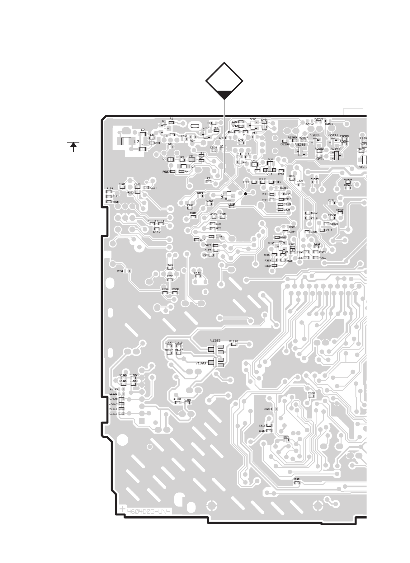
Hauptplatte
Main board
PL 4604 D05
Chip
MP158
(FS)
Meßpunkte / Measurement points
- 3 -
Page 4

Main Feature list Funline3
Düsseldorf
Kansas
Features
FM-Preset 2x6 2x6 2x6 2x6 2x6 2x6
MW-Preset 1x6 1x6 1x6
LW-Preset 1x6 1x6 1x6
FMT 1x6 1x6 1x6 1x6 1x6 1x6
HICUT √√ √ √√ √
lo/dx 3/3 3/3 3/3 3/3 3/3 3/3
Mechanism CC TN708 TN708
Dolby B √√
Metal √√
S-CPS √√
Repeat √√
Radio Monitor √√
Mechanism CD BP4 BP4 BP4 BP4
Track Mix √√√ √
Track Repeat √√√ √
Track Scan √√√ √
X-Bass 3 steps 3 steps 3 steps 3 steps
Loudness ON/OFF 6 steps 6 steps
Preamp 4 x 3V 4 x 3V 4 x 3V 4 x 3V 4 x 3V 4 x 3V
Display negative negative negative negative negative negative
Flip Panel √√ √ √√ √
DMS ASCI ASCI ASCI ASCI ASCI ASCI
Code for IDC A09 √√ √ √√ √
Dimmer √√ √ √√ √
AUX IN √√ √ √√ √
Tel IN √√ √ √
Radio Mute √√ √ √√ √
IR RC08/RC10 optional optional optional optional optional optional
Peak Level Meter √√ √ √√ √
Clock √√ √ √√ √
Release Panel √√ √ √√ √
RP Case √√ √ √√ √
Bologna
Maryland
Hawaii
München Modena Wiesbaden Sevilla
- 4 -
Page 5

Main Feature list T-Line2
Features
FM-Preset 2x5 2x5 2x5 2x5 2x5 2x5 2x5 2x5 2x5 2x5
MW-Preset 1x5 1x5 1x5 1x5 1x5 1x5 1x5
LW-Preset 1x5 1x5 1x5 1x5 1x5 1x5 1x5
FMT 1x5 1x5 1x5 1x5 1x5 1x5 1x5 1x5 1x5 1x5
HICUT √ √√√√√√√√√
lo/dx 3/3 3/3 3/3 3/3 3/3 3/3 3/3 3/3 3/3 3/3
Mechanism CC ADC 1400 ADC 1400 TN708 TN708
Dolby B B B B
Metal √√√√
S-CPS √√√√
Repeat √√√√
Mechanism CD BP4 BP4 BP4 BP4 BP4 BP4
Track Mix √√√√√√
Track Repeat √√√√√√
Track Scan √√√√√√
X-Bass 3 steps 3 steps 3 steps 3 steps 3 steps 3 steps 3 steps 3 steps 3 steps 3 steps
Preamp 4 x 3V 4 x 3V 4 x 3V 4 x 3V 4 x 3V
DMS ASCI ASCI ASCI ASCI ASCI ASCI ASCI ASCI ASCI ASCI
Code for IDC A09 √ √√√ √√√
AUX IN √ √√ √√√√√√√
Tel IN √√ √√√
Radio Mute √ √√ √√√√√√√
IR Remote Control RC08/RC10 optional optional optional optional optional optional optional optional optional optional
Peak Level Meter √ √√√√√√√√√
Clock manual √ √√ √√√√√√√
Facia colour black black titanium titanium black black titanium titan/chrom titan/chrom titan/chrom
Release Panel √ √√ √√√√√√√
RP Case √ √√ √√√√√√√
Cleveland
Dresden
Dublin
Boston
Madison
Freiburg
Las V egas
Canberra
San Diego
Essen Lausanne Alicante Konstanz San Remo Santa Cruz
- 5 -
Page 6
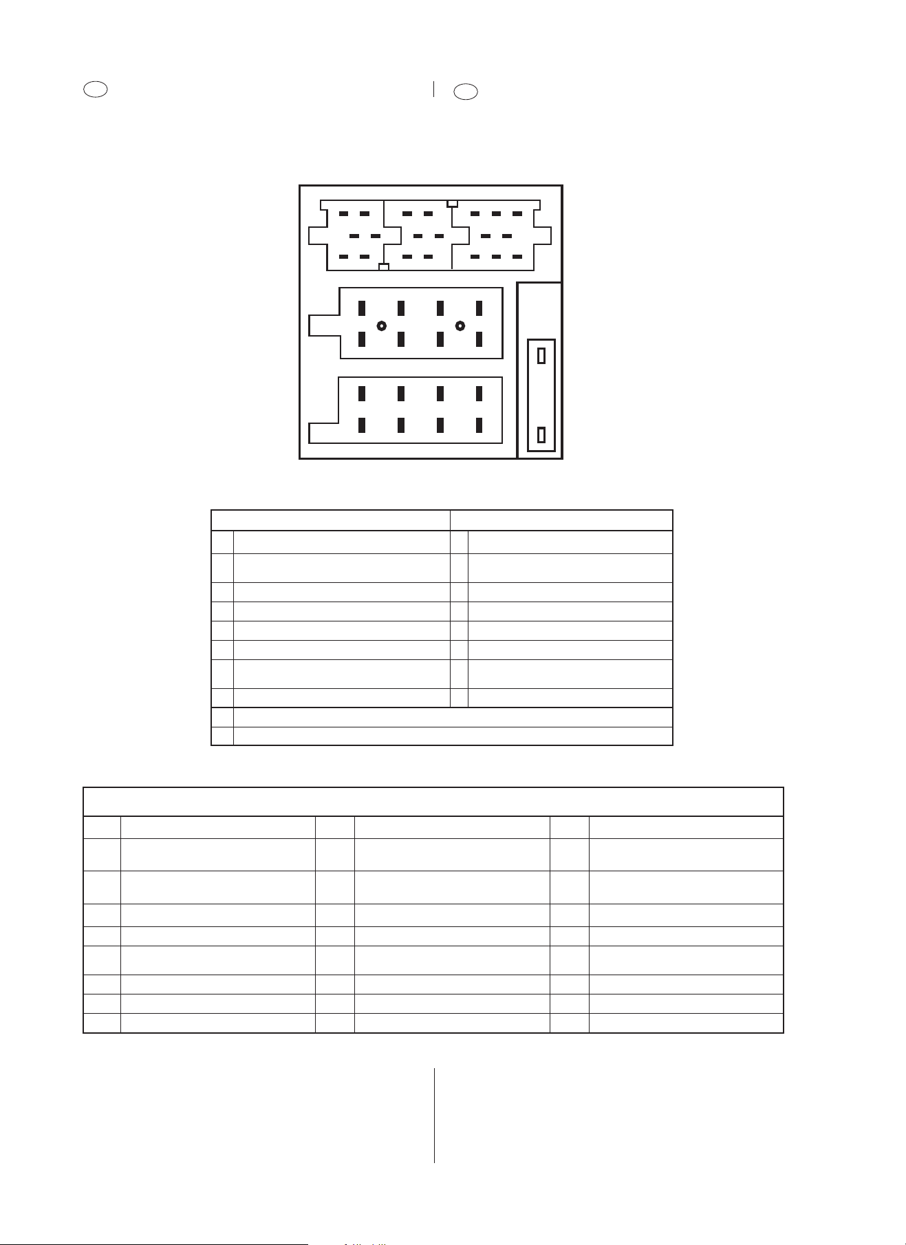
D
Belegung des Anschlußkästchens
GB
Pin assignment of quickfit connector
C-1 C-2 C-3
* Nur Funline 3 Geräte
* only Funline 3 units
16
19
15
18
20
7
8
7
8
C
B
A
7
3
4
3
4
10 13
9
12
5
b
6
5
6
14
6
3
581114 17
2
1
a
2
1
2
AB
1 NC 1 Speaker Out (RR +) 4Ω
2 <2volts = active; open = not active
3 NC 3 Speaker Out (RF +) 4Ω
4 Permanent plus (KL 30); 10 A 4 Speaker Out (RF-) 4Ω
5 Automatic antenna 5 Speaker Out (LF +) 4Ω
*6 Illumination, active high (3 - 12 volts) 6 Speaker Out (LF-) 4Ω
7 <2.5volts = Ign.off; >7volts = Ign.on 7
8 Ground 8 Speaker Out (LR-) 4Ω
a MAUS-BUS-OUT (TXD) <0.5volts = logic 0; >3.5volts = logic 1
b MAUS-BUS-IN (RXD) <1volt = logic 0; >3.5volts = logic 1
Radio mute 2 Speaker Out (RR -) 4Ω
Ignition plus, (KL 15) Speaker Out (LR +) 4Ω
(+) Nur Funline 3 Geräte / (+) only Funline 3 units
C
C1 C2 C3
*1 Line out, 3V/10kΩ (LR) 7 Tel.-/Navi. AF In 10V/560Ω 13 CD-Changer ASCI IN / +TMC-Out
*2 Line out, 3V/10k
*3 Line out ground 9 NC 15 CDC permanent plus (bloc A / pin 4)
*4 Line out out, 3V/10kΩ (LF) 10 +12 V switched 16 +12 V switched
*5 Line out out, 3V/10k
*6 +12 V switched 12 Remote control Ground 18 Aux Ground
* Nicht Cleveland, Boston, Dresden, Dub lin, Madison, Essen,
Lausanne und Alicante.
IG für A/Pin5; C1/Pin6; C2/Pin10 + C3/P = 300 mA.
Ω (RR) 8 Tel.-/Navi. AF In 10V/560Ω 14 CD-Changer ASCI OUT / +TMC-Out
Ω (RF) Remote control PWM 17 CD-Changer I
11 <1volt = logic 0; >3.5volts = logic 1
( Not Sevilla + Wiesbaden) <1volt = logic 0; >3.5volts = logic 1
( Not Sevilla + Wiesbaden) <0.5volt = logic 0; >3.5volts = logic 1
2
C-Bus Masse / Gnd.
19 Aux input 2V/6kΩ (L)
20 Aux input 2V/6kΩ (R)
* Not Cleveland, Boston, Dresden, Dub lin, Madison, Essen,
Lausanne und Alicante.
IG for A/Pin5; C1/Pin6; C2/Pin10 + C3/P = 300 mA.
- 6 -
Page 7

D
Abgleichhinweise
GB
Notes on alignment
Der Abgleich erfolgt nur noch elektronisch über
den PC (ComServer ). Es dürfen keine Filter
abgeglichen werden. Nach dem Tausch eines
Filters, mss der Abgleich über den PC erfolgen.
Wellenbereich:
FM = 87,5 MHz - 108,0 MHz
(100 kHz automatische Suchlaufschritte)
(50 kHz manuelle Suchlaufschritte)
MW = 531 kHz - 1602 kHz
(9 kHz automatische Suchlaufschritte)
(9 kHz manuelle Suchlaufschritte)
LW = 153 kHz - 279 kHz
(9 kHz automatische Suchlaufschritte)
(1 kHz manuelle Suchlaufschritte)
Vorbereitende Arbeiten
Bevor Sie den elektrischen Abgleich durchführen, müssen Sie
folgende Vorbereitungen treffen:
Höhen - Einstellung ........................................................................0
Bass - Einstellung .......................................................................... 0
Fader - Einstellung (nicht Lübeck/Luxembourg) ............................ 0
Balance - Einstellung ......................................................................0
Loudness - Einstellung (DSC Menü) ............................. 1 oder OFF
X-Bass - Einstellung (DSC Menü) .............................................OFF
The alignment is always done electronically using
a PC (ComServer). Do not align any filters. If a
filter has been replaced, align the unit with the PC.
Waveband:
FM = 87.5 MHz - 108.0 MHz
(100 kHz automatic search steps)
(50 kHz manual search steps)
MW = 531 kHz - 1602 kHz
(9 kHz automatic search steps)
(9 kHz manual search steps)
LW = 153 kHz - 279 kHz
(9 kHz automatic search steps)
(1 kHz manual search steps)
Preparatory steps
Observe the following preparations before performing the electrical
alignment:
Treble adjustment .......................................................................... 0
Bass adjustment ............................................................................ 0
Fader adjustment (not Lübeck/Luxembourg) ................................. 0
Balance adjustment ........................................................................0
Loudness adjustment (DSC menu) ................................... 1 or OFF
X-Bass adjustment (DSC menu) ...............................................OFF
Lautsprecheranschluß
Der Lautsprecherausgang muß mit 4 Ω abgeschlossen sein.
Demomode
Demomode aktivieren
1. Schalten Sie das Autoradio aus.
2. Betätigen Sie die Tasten 1 + 6 (Funline 3); 1 + 5 (T-Line 2)
gleichzeitig und halten Sie die Tasten gedrückt.
3. Schalten Sie das Gerät ein und halten Sie die Tasten noch für
ca. 1 Sekunde gedrückt.
Nach diesem Schritt erscheint im Display nach "BLAUPUNKT" der
Schriftzug "Demo".
Demomode deaktivieren
Sie verlassen den Servicemode durch Ausschalten des Autoradios.
Wiederholen Sie bitte den Schritt 1-3 um den Demomode zu
verlassen.
Software Version Hauptprozessor und
Kappenprozessor
Testmode aktivieren
1. Schalten Sie das Autoradio aus.
2. Betätigen Sie die Tasten 1 + 2 gleichzeitig und halten Sie die
Tasten gedrückt.
3. Schalten Sie das Gerät ein und halten Sie die Tasten noch für
ca. 1 Sekunde gedrückt.
Loudspeaker connections
The loudspeaker output must be terminated with 4 Ω.
Demo mode
Activating the Demo mode
1. Switch the unit off.
2. Press the push-buttons 1 + 6 (Funline 3); 1 + 5 (T-Line 2)
simultaneously and hold them depressed.
3. Switch the unit back on and hold on to the buttons for
approximately one more second.
Following this step, the display will show the wording “BLAUPUNKT” followed by “Demo”.
Deactivating the Demo mode
You can quit the service mode by switching the radio off.
Wiederholen Sie bitte den Schritt 1-3 um den Demomode zu
verlassen.
Software version main processor and
panel prozessor
Activating the test mode
1. Switch the unit off.
2. Press the push-buttons 1 + 2 simultaneously and hold them
depressed.
3. Switch the unit back on and hold on to the buttons for
approximately one more second.
Das Autoradiodisplay zeigt 8 Zeichen an.
Die 4 linken Zeichen zeigen den Softwarestand des Hauptprozessors an und die 4 rechten Zeichen zeigen den Softwarestand
des Kappen- prozessors an.
Testmode deaktivieren
Sie verlassen den Service Mode durch Ausschalten des Autoradios.
The car radio display shows 8 characters.
The left 4 characters indicate the software version of the main
processor, the right 4 characters indicate the software version of
the panel processor.
To exit the test mode
You can quit the service mode by switching the radio off.
- 7 -
Page 8
Antennenanpassung
D
Antenna matching
GB
E' - Beispiele bei FM und AM
E' = Bezugspunkt (unbelasteter Ausgang der Anpaßschaltung/
künstliche Antenne) in dBµV.
Y = Meßsendereinstellung in dBµV oder µV.
V = Meßsenderbedämpfung durch die Eingangsimpedanz der
Anpaßschaltung (Leistungsanpassung).
X = Dämpfung der künstlichen Antenne in dB.
Meßsender / signal generator: Meguro, Leader, Kenwood
Künstliche Antenne AM: Künstliche Antenne FM:
Dummy antenna AM: Dummy antenna FM:
E' (40 dBµV)Y
Meguro
Leader
Kenwood
V = 6 dB
X = 14 dB
X = 20 dB
E' - examples for FM and AM
E' = reference point (output of matching device/dummy antenna
without load) in dBµV.
Y = adjustment of the signal generator in dBµV or µV.
V = attenuation of the signal generator output due to the load applied
by the matching device (power adaptation).
X = attenuation of the dummy antenna in dB.
E’ (40 dBµV)
Meguro
Leader
Kenwood
Y
V = 6 dB
Y = V + X + E'
(X =14 dB) Y = 6 dB + 14 dB + 40 dBµV
Y = 60 dBµV = 1 mV
(X =20 dB) Y = 6 dB + 20 dB + 40 dBµV
Y = 66 dBµV = 2 mV
dB- Umrechnungstabelle
dB0123456789
01 1,12 1,26 1,41 1,59 1,78 2,00 2,24 2,51 2,82
10 3,16 3,55 3,98 4,47 5,01 5,62 6,31 7,08 7,94 8,91
20 10,0 11,2 12,6 14,1 15,9 17,8 20,0 22,4 25,1 28,2
30 31,6 35,5 39,8 44,7 50,1 56,2 63,1 70,8 79,4 89,1
40 100 112 126 141 159 178 200 224 251 282
50 316 355 398 447 501 562 631 708 794 891
60 1 000 1 122 1 259 1 413 1 585 1 778 1 995 2 239 2 512 2 818
70 3 162 3 548 3 981 4 469 5 012 5 623 6 310 7 080 7 943 8 912
Y = V + E'
Y = 6 dB + 40 dBµV
Y = 46 dBµV = 200 µV
dB Conversion table
Faktoren / Factors
- 8 -
Page 9
MAUS - Software + Hardware
D
(MAUS = Multifunktionsbus für
Abgleich Und Start Up)
GB
MAUS software + hardware
(MAUS = multi-function bus for
alignment and start-up)
PC - Vorausetzungen
IBM - Kompatibler Computer: Ab Pentium 2 oder höher
Betriebssystem: Windows 95/98 + WinNT4
MAUS Ausstattung
a) "ComServer" (Software + Dongletreiber + Lies mich Datei
+ Serviceanleitungen MAUS)
8 627 003 058 (CD-Rom)
b) Konfigurationsdateien (MAUS-Bus-Kommandos + Servicean-
leitung MAUS) für die F3/T2 Geräte mit der Bestellnummer
1
8 627 003 072 (1 Diskette MS DOS 3
/2 Zoll)
Required PC equipment
IBM-compatible computer: Pentium 2 or higher
Operating system: Windows 95/98 + WinNT4
MAUS equipment
a) "ComServer" (software + dongle driver + read me file
+ service manuals MAUS)
8 627 003 058 (CD-Rom)
b) Configuration files (MAUS bus commands + service manual
MAUS) for the F3/T2 units with order number
1
8 627 003 072 (1 MS DOS 3
/2 inch diskette).
c) Interface (MAUS-Bus / K-Bus auf RS232 Schnittstelle)
8 627 004 057
d) Steckernetzteil für Interface (12V / 500 mA)
8 627 004 061
e) Dongle (Hardware Sicherheitssystem in Verbindung mit dem
MAUS-Bus)
8 627 004 059 (nur für decodierberechtigte Servicestellen)
Achtung: Bitte stecken Sie den "DONGLE"
nur bei ausgeschalteten PC auf die
LPT Drucker schnittstelle.
f) Maus Bus Kabel (Lautsprecher - ISO Stecker mit 2 Kontakt
nadeln)
8 627 004 042
c) Interface (MAUS-bus / K-bus to RS232 interface)
8 627 004 057
d) Power adapter (12 V / 500 mA)
8 627 004 061
e) Dongle (hardware security system in connection with the
MAUS-bus)
8 627 004 059 (for authorised decoding agents only)
Warning: Please plug the "DONGLE" into
the printer port only if the PC is
switched "OFF".
f) MAUS bus cable
(speaker - ISO connector with 2 contact pins)
8 627 004 042
g) Verlängerungskabel RS232 (PC zum Interface)
8 627 004 015
g) Extension cable RS232 (PC to interface)
8 627 004 015
- 9 -
Page 10

MAUS - Software + Hardware
D
(MAUS = Multifunktionsbus für
Abgleich Und Start Up)
GB
MAUS software + hardware
(MAUS = multi-function bus for
alignment and start-up)
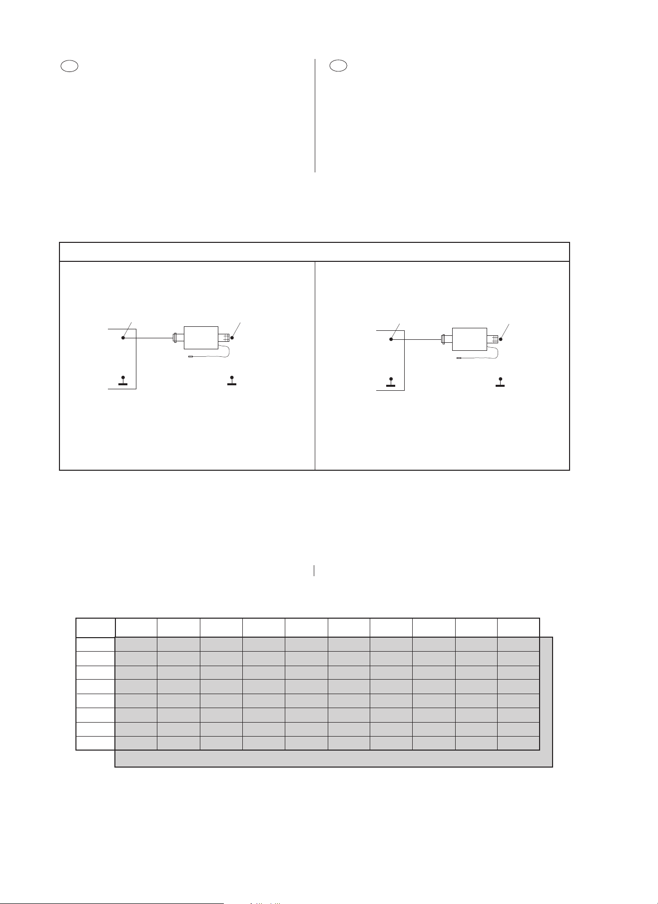
Hardware installieren
Achtung: Zerstörungsgefahr des Interface-
kastens 8 627 004 057:
1. Bitte verbindenen Sie die Interfacemasse
(8 627 004 057) mit der Autoradiomasse
(Potentialausgleich).
2. Folgende Reihenfolge ist beim Anschluß
des Autoradios in Verbindung mit dem
Mausbuskabel 8 627 004 042 einzuhalten:
a) Mausbuskabel anschließen.
b) Danach Stromkabel anschließen.
Nach der Bearbeitung des Autoradios muß in
umgekehrter Reihenfolge verfahren werden.
Verlängerung 8 627 004 015
Extension cable 8 627 004 015
Hardware installation
Warning: Danger of damaging the interface box
8 627 004 057:
1. Connect the ground terminal of the
interface (8627 004 057) and the car
radio with each other (equal potential).
2. The following hook-up sequence must be
observed when connecting the car
radio and the MAUS bus cable 8 627 004 042 :
a) First connect the MAUS bus cable.
b) Then hook up the power cable.
Proceed the other way round after having
finished work on the car radio.
PC
COM PORT
Interface 8 627 004 057
(Rückseite / rear side)
Interface 8 627 004 057
(Vorderseite / front side)
Anschlußkabel 8 627 004 042
Connecting cable 8 627 004 042
Schalterstellung des Interface
Bitte achten Sie auf die beiden Einstellungen der Schalter "BusSystem" und "MODUS".
Netzteil 8 627 004 061
Power adapter 8 627 004 061
Skyline Anschlußkasten
Skyline connector box
Interface box settings
Please check the settings of the "Bus-System" and "MODUS"
(mode) selectors.
Der Schalter "Bus-System" muß auf M stehen.
Der Schalter "MODUS" muß auf invers stehen.
The "Bus-System" selector must be set to M (MAUS-Bus).
The "MODUS" selector must be set to invers .
- 10 -
Page 11

D
Bevor Sie mit der folgenden Bearbeitung beginnen, installieren
Sie bitte erst die Software und verbinden Sie die Hardware
Komponenten (siehe Seite 10).
GB
Install the software and connect the hardware components
(see page 10) before you start with the following steps.
F3/T2_ASB_EU CFG Datei installieren
1. Schalten Sie den PC ein und warten bis der Boot - Vorgang
beendet ist. Danach starten Sie bitte Windows 95/98/NT4.
2. Öffnen Sie den Windows Explorer Ihres PC`s und rufen Sie das
Diskettenlaufwerk A auf.
F3/T2
3. Legen Sie die 3 1/2 Zoll Diskette "
( 8 627 003 072) in das Diskettenlaufwerk "A" Ihres PC´s ein.
4. Klicken Sie mit einem Doppelklick der Maus auf "Setup".
_ASB_EU"
Installation of
1. Switch on the PC and wait until it has booted. Then start
Windows 95/98/NT4.
2. Open diskette drive A in the Explorer.
3. Insert the 3 1/2" diskette "
into drive A of your PC.
4. Double-click "Setup".
F3/T2
_ASB_EU CFG file
F3/T2
_ASB_EU" ( 8 627 003 072)
5. In dem nächsten Bild können Sie zwischen den Sprachen
"Deutsch" und "English" wählen.
5. On the next screen you can choose between
the languages “Deutsch” and “English”.
- 11 -
Page 12

F3/T2_ASB_EU CFG Datei installieren
D
GB
Installation of
F3/T2
_ASB_EU CFG file
6. In dem nächsten Bild bestätigen bitte Sie mit "Weiter".
6. Please click "Next" in the following screen.
7. Sollte eine Fehlermeldung erscheinen, so bestätigen Sie bitte
mit "OK".
8. Sie bestätigen das vorgegebene Verzeichnis mit "Weiter".
7. If an error message appears, press “OK” to confirm.
8. Press “Next“ to confirm the default directory.
- 12 -
Page 13

F3/T2_ASB_EU CFG Datei installieren
D
GB
Installation of
F3/T2
_ASB_EU CFG file
9. In dem nächsten Bild wird Ihnen die Datei angezeigt, die in das
vorgegebene Verzeichnis kopiert wird.
Bitte bestätigen Sie mit "WEITER".
9. The next screen presents the data which is copied into the
default directory.
Please press “Next” to confirm.
10. Die F3/T2_ASB_EU Datei wird nun in das Standart-Verzeichnis
des ComServers 4.0 geladen.
Bitte bestätigen Sie mit "Beenden".
10. The F3/T2_ASB_EU file is now loaded into the standard
directory of the ComServers 4.0.
Please press “Finish” to confirm.
- 13 -
Page 14

Com Port setzen
D
1. Um die Verbindung zwischen Interface und PC herzustellen
müssen Sie nun Ihren PC auf die richtige Eingangsbuchse
stellen (Com Port).
GB
Setting the Com port
1. To provide a connection between the interface and the PC, you
must now set the correct communication port.
2. Bitte starten Sie den Comserver mit einem Doppelklick der
Maus auf das Icon "ComServ".
3. In der oberen Menuebake des ComServers müssen Sie den
Punkt "Konfiguration" + "Schnittstellen" auswählen.
2. Double-click the "ComServ" icon to start the ComServer.
3. Choose the item "Schnittstellen" (interface) from the "Konfiguration" menu.
4. Stellen Sie nun die von Ihnen gewünschte Schnittstelle
(V24 Port) ein und bestätigen mit "OK".
Danach speichern Sie die Einstellungen.
4. Then set the desired interfaces (V24 port) and confirm with
"OK". Click "OK" to store your settings.
- 14 -
Page 15

Konfigurationsdatei laden
D
GB
Loading the configuration file
1. Schalten Sie den PC ein und warten bis der Boot - Vorgang
beendet ist. Danach starten Sie bitte Windows 95/98/NT4 und
dann den ComServer.
2. Bitte starten Sie den Comserver mit einem Doppelklick der
Maus auf das Icon "ComServ".
3. In der oberen Menuebake des ComServers müssen Sie den
Punkt "Datei"; "Laden" auswählen.
1. Switch on the PC and wait until it has booted. Then start
Windows 95/98/NT4 and the ComServer.
2. Double-click the "ComServ" icon to start the ComServer.
3. Choose the item "Laden" (load) from the "Datei" (file) menu of
the ASE - ComServer.
4. Wählen Sie bitte C/Programme/ASE/ComServ/VKD /F3_T2
und "F3/T2_ASB_EU.cfg" aus .
4. Select C/Programme/ASE/ComServ/VKD /F3_T2 and
"F3/T2_ASB_EU.cfg".
- 15 -
Page 16

Konfigurationsdatei laden
D
5. Es erscheint folgende Bearbeitungsmaske:
GB
Loading the configuration file
5. You will see the following processing screen:
- 16 -
Page 17

EEPROM programmieren
D
GB
Programming the EEPROM
1. Starten Sie das Kommando "Level 0 protected" mit dem
Doppelklick der Maus.
2. In der nächsten Aufforderung ist die Reihenfolge
einzuhalten:
a) Schalten Sie das Netzteil aus.
b) Bestätigen Sie im Dialogfeld mit OK (Mausklick oder ENTER).
c) Danach schalten Sie das Netzteil ein.
1. Double-click the command "Level 0 protected" as illustrated.
2. Then proceed as follows (make sure to observe the correct
sequence):
a) Turn off the power supply.
b) Confirm with OK in the dialogue field (mouse click or ENTER).
c) Turn the power supply on again.
3. Im Ausgabefenster des ComServers sollte "Maus Bus OK,
Communication = OK" erscheinen.
Erscheint "Init = 249" muß die Prozedur wiederholt werden.
3. "Maus Bus OK, Communication = OK" should appear in the
ComServer output window.
You must repeat the procedure if „Init = 249“ appears
- 17 -
Page 18

EEPROM programmieren
D
GB
Programming the EEPROM
4. Starten Sie die Prozedur mit einem Doppelklick auf das
Kommando z.B.: "Bologna C51".
Im Ausgabefenster des ComServers erscheint 10 x "EEPROM set =
OK".
4. Start the Start Up procedure by double-clicking for example
"Bologna C51" command.
The ComServer’s output window appears 10 x "EEPROM set =
OK".
Nach dem "Start up" müssen folgende Arbeiten durchgeführt
werden
• DAA programmieren (Ableich Vor-und Zwischenkreis)
• FM ZF programmieren
• LSL + LST FM programmieren (Abgleich FM-Feldstärke)
• LST AM programmieren (Abgleich AM-Feldstärke)
• Stereo Schaltschwelle programmieren
• FM - Suchlauf - Stopschwellen programmieren
• AM-MW/LW - Suchlauf - Stopschwellen programmieren
• RDS Schwelle programmieren
• Auslieferungszustand programmieren
(die Reihenfolge ist einzuhalten):
The following Maus bus commands have to be executed after a
"Start up"
• DAA programming (alignment of front- and intermediate r-f circuit)
• FM IF offset programming
• FM LSL + LST programming (alignment of FM field strength)
• AM LST programming (alignment of AM field strength)
• Stereo threshold programming
• FM search stop programming
• AM-MW/LW search stop programming
• FM-RDS sensitivity programming.
• Deafult settings
- 18 -
(proceed according to the sequence as stated below):
Page 19

DAA Programmierung
D
GB
Programming DAA
Künstliche Antenne verwenden.
Betriebsart ............................... FM
Signalquelle ............................. Meßsender
f = 87,5 MHz, f
Hub = 22,5 kHz
Signaleingang .......................... E' = 30 dBµV (+Bedämpfung!)
1. Klicken Sie mit einem Doppelklick der Maus auf das Kommando
"Level 1".
Bitte ignorieren Sie die nächste Aufforderung und bestätigen im
Dialogfeld mit OK (Mausklick oder ENTER).
2. Stellen Sie den Meßsender auf 87,5 MHz, mit 22,5 kHz Hub
und 1 kHz Modulation ein.
3. Speisen Sie das HF-Signal E' = 30 dBµV in die Antennenbuchse des Autoradios ein (Dämpfung der künstlichen Antenne
beachten).
4. Klicken Sie mit einem Doppelklick der Maus auf das Kommando
"Set PLL to 87,5 MHz".
Im Ausgabefenster des ComServers sollte "PLL set to
FM = OK, PLL set to 87,5 NHz = OK" erscheinen.
5. Klicken Sie mit einem Doppelklick der Maus auf das Kommando
"DAA1".
Danach erscheint eine Maske mit den Meßsendereinstellungen.
= 1 kHz
mod
Use the dummy antenna.
Operating mode ....................... FM
Signal source ........................... Signal generator
f = 87.5 MHz, f
Hub = 22,5 kHz
Signal input .............................. E' = 30 dBµV (+attenuation!)
1. Double-click the command "Level 1" as illustrated.
Please ignore the next system prompt and confirm this dialogue
box with OK (mouse click or by pressing the RETURN key).
2. Adjust the signal generator to 87,5 MHz, modulated with 1 kHz,
22,5 kHz deviation.
3. Feed the RF signal E' = 30 dBµV into the antenna input
(observe the attenuation of the dummy antenna).
4. Double-click the command "Set PLL to 87,5 MHz".
The ComServer’s output window should read "PLL set to
FM = OK, PLL set to 87,5 NHz = OK".
5. Double-click the command "DAA1".
A screen then appears showing the signal generator settings.
= 1 kHz
mod
6. Bestätigen Sie im Dialogfeld mit OK (Mausklick oder ENTER).
Im Ausgabefenster des ComServers sollte "DAA1 = OK"
erscheinen.
7. Klicken Sie mit einem Doppelklick der Maus auf das Kommando
"DAA2".
Danach erscheint eine Maske mit den Meßsendereinstellungen.
8. Ändern Sie die Frequenz des Meßsenders auf 95 MHz.
9. Bestätigen Sie im Dialogfeld mit OK (Mausklick oder ENTER).
Im Ausgabefenster des ComServers sollte "DAA2 = OK"
erscheinen.
10. Klicken Sie mit einem Doppelklick der Maus auf das Kommando
"DAA3".
Danach erscheint eine Maske mit den Meßsendereinstellungen.
6. Confirm with OK in the dialogue field (mouse click or ENTER).
The ComServer’s output window should read "DAA1 = OK".
7. Double-click the command "DAA2".
A screen then appears showing the signal generator settings.
8. Change the frequency of the signal generator to 95 MHz.
9. Confirm with OK in the dialogue field (mouse click or ENTER).
The ComServer’s output window should read "DAA2 = OK".
10. Double-click the command "DAA3".
A screen then appears showing the signal generator settings.
- 19 -
Page 20

DAA Programmierung
D
GB
Programming DAA
11. Ändern Sie die Frequenz des Meßsenders auf 108 MHz.
12. Bestätigen Sie im Dialogfeld mit OK (Mausklick oder ENTER).
Im Ausgabefenster des ComServers sollte "DAA3 = OK"
erscheinen.
13. Klicken Sie mit einem Doppelklick der Maus auf das Kommando
"Finish Programm DAA".
Im Ausgabefenster des ComServers erscheint "Programm DAA
Finish = OK".
11. Change the frequency of the signal generator to 108 MHz.
12. Confirm with OK in the dialogue field (mouse click or ENTER).
The ComServer’s output window should read "DAA3 = OK".
13. Double-click the command "Finish Programm DAA".
The ComServer’s output window appears "Programm DAA
Finish = OK".
- 20 -
Page 21

Programmierung der FM-ZF
D
GB
Programming of the FM IF offset
Künstliche Antenne verwenden.
Betriebsart ............................... FM
Meßpunkt ................................. MP158 (FS)
Meßinstrument......................... Oszilloskop
Signalquelle ............................. Meßsender
f = 98,1 MHz, f
Hub = 75 kHz
Signaleingang .......................... E' = 30 dBµV (+Bedämpfung!)
1. Stellen Sie den Meßsender auf 98,1 MHz, mit 75 kHz Hub und
1 kHz Modulation ein.
2. Speisen Sie das HF-Signal E' = 30 dBµV in die Antennenbuchse des Autoradios ein (Dämpfung der künstlichen Antenne
beachten).
3. Klicken Sie mit einem Doppelklick der Maus auf das Kommando
"Set PLL to 98.1 MHz".
Im Ausgabefenster des ComServers sollte "PLL set to
FM = OK; PLL set to 98.1 MHz = OK" erscheinen.
4. Schließen Sie das Oszilloskop an Meßpunkt MP158 (FS) an.
5. Klicken Sie mit einem Doppelklick der Maus auf das Kommando
"Adjust IF Offset".
Danach erscheint eine Maske mit den Meßsendereinstellungen.
6. Wenn Sie die richtigen Meßsender-Einstellungen gewählt
haben, klicken Sie auf OK.
In der nächsten Maske erscheint "-12.5 kHz; 0.0 kHz; +12.5 kHz".
7.
Klicken SIe zweimal auf die Einstellung (z.B. - 12,5kHz), bei
der das AM Minimum am geringsten ist.
Im Ausgabefenster des ComServers sollte "Adjust IF = OK"
erscheinen.
= 1 kHz
mod
Use the dummy antenna.
Operating mode ....................... FM
Measuring point ....................... MP158 (FS)
Measuring instrument .............. oscilloscope
Signal source ........................... Signal generator
f = 98.1 MHz, f
Hub = 75 kHz
Signal input .............................. E' = 30 dBµV (+attenuation!)
1. Adjust the signal generator to 98.1 MHz, modulated with 1 kHz,
75 kHz deviation.
2. Feed the RF signal E' = 30 dBµV into the antenna input
(observe the attenuation of the dummy antenna).
3. Double-click the command "Set PLL to 98.1 MHz".
The ComServer’s output window should read "PLL set to
FM = OK; PLL set to 98.1 MHz = OK".
4. Connect an oscilloscope to MP158 (FS).
5. Double-click the command "Adjust IF Offset".
A screen then appears showing the signal generator settings.
6. If you have selected the right signal generator setting, click OK.
7.
The next mask shows “-12.5 kHz; 0.0 kHz; +12.5 kHz”.
Click twice the adjustment with the lowest AM minimum
(e.g. - 12.5kHz).
The ComServer’s output window should read "Adjust IF = OK".
= 1 kHz
mod
8
. Danach klicken SIe mit einem Doppelklick der Maus auf das
Kommando "IF Offset programming".
In der nächsten Maske erscheint "-12.5 kHz; 0.0 kHz;
+12.5 kHz".
9. Bitte klicken Sie mit einem Doppelklick auf den in Punkt 7
ermittelten AM Minimum Wert (z.B. - 12,5kHz).
Im Ausgabefenster des ComServers sollte "Programming
IF = OK" erscheinen.
• Im Anschluß fahren Sie bitte sofort mit der Programmierung FM LST/LSL fort.
8
. Double-click the command "IF Offset programming".
Then double-click the command “IF Offset programming”.
The next mask shows “-12.5 kHz; 0.0 kHz; +12.5 kHz”.
9. Now please double-click the AM minimum value identified under
item 7 (e.g. - 12.5kHz).
The ComServer’s output window should read "IProgramming
IF = OK".
• Then continue with the programming of FM LST/LSL.
- 21 -
Page 22

FM Feldstärke programmieren
D
GB
Programming of the FM fieldstrengh
Künstliche Antenne verwenden.
Betriebsart ............................... FM
Meßpunkt ................................. MP158 (FS)
Meßinstrument......................... Digitalvoltmeter
Signalquelle ............................. Meßsender
f = 95 MHz, f
Hub = 22,5 kHz
Signaleingang .......................... E' = 10 dBµV / 50 dBuV
(+Bedämpfung!)
1. Stellen Sie den Meßsender auf 98,1 MHz, mit 22,5 kHz Hub
und 1 kHz Modulation ein.
2. Speisen Sie das HF-Signal E' = 10 dBµV in die Antennenbuchse des Autoradios ein (Dämpfung der künstlichen Antenne
beachten).
3. Klicken Sie mit einem Doppelklick der Maus auf das Kommando
"Set PLL to 95 MHz".
Im Ausgabefenster des ComServers sollte "PLL set to
FM = OK; PLL set to 95 MHz = OK" erscheinen.
4. Klemmen Sie das Digitalvoltmeter an MP158 (FS) an.
5. Klicken Sie mit einem Doppelklick der Maus auf das Kommando
"Decrease LST".
Danach erscheint eine Maske mit den Meßsendereinstellungen
und den Hinweis, daß Sie den Befehl "LST" solange wiederholen müssen, bis Sie an MP158 (FS) 950 mV ± 25 mV messen.
= 1 kHz
mod
Use the dummy antenna.
Operating mode ....................... FM
Measuring point ....................... MP158 (FS)
Measuring instrument .............. digital voltmeter
Signal source ........................... Signal generator
f = 95 MHz, f
Hub = 22.5 kHz
Signal input .............................. E' = 10 dBµV / 50 dBuV
(+attenuation!)
1. Adjust the signal generator to 98.1 MHz, modulated with 1 kHz,
22.5 kHz deviation.
2. Feed the RF signal E' = 10 dBµV into the antenna input
(observe the attenuation of the dummy antenna).
3. Double-click the command "Set PLL to 95 MHz".
The ComServer’s output window should read "PLL set to
FM = OK; PLL set to 95 MHz = OK".
4. Connect the digital voltmeter to MP158 (FS).
5. Double-click the command "Decrease LST".
The system will then display a mask including the signal
generator settings and the information that the “LST” command
has to be repeated until a voltage of 950 mV ± 25 mV applies at
MP158 (FS).
= 1 kHz
mod
6. Ändern Sie das HF-Signal auf E' = 50 dBµV (+Bedämpfung!).
7. Danach klicken Sie mit einem Doppelklick der Maus auf das
Kommando "Decrease LSL".
Danach erscheint eine Maske mit den Meßsendereinstellungen
und den Hinweis, daß Sie den Befehl "LSL" solange wiederholen müssen, bis Sie an MP158 (FS) 2,54 V ± 0,1 V messen.
8. Danach klicken SIe mit einem Doppelklick der Maus auf das
Kommando "FM LST/LSL programming".
Im Ausgabefenster des ComServers sollte "LST/LSL = set"
erscheinen.
6. Change the RF signal to E’ = 50 dBµV (+attenuation!).
7. Double-click the command "Decrease LSL".
The system will then display a mask including the signal
generator settings and the information that the “LSL” command
has to be repeated until a voltage of 2.54 V ± 0.1 V applies at
MP158 (FS).
8. Double-click the command "FM LST/LSL programming".
The ComServer’s output window should read "LST/LSL = set".
• Im Anschluß fahren Sie bitte sofort mit der Programmierung AM LST fort.
• Then continue with the programming of AM LST.
- 22 -
Page 23

AM Feldstärke programmieren
D
GB
Programming of the AM fieldstrengh
Künstliche Antenne verwenden.
Betriebsart ............................... AM
Meßpunkt ................................. MP158 (FS)
Meßinstrument......................... Digitalvoltmeter
Signalquelle ............................. Meßsender
f = 1062 kHz, f
mod = 30 %
Signaleingang .......................... E' = 30 dBµV (+Bedämpfung!)
1. Stellen Sie den Meßsender auf 1062 kHz, mit 30 %
Modulationsgrad und 1 kHz Modulation ein.
2. Speisen Sie das HF-Signal E' = 30 dBµV in die Antennenbuchse des Autoradios ein (Dämpfung der künstlichen Antenne
beachten).
3. Klicken Sie mit einem Doppelklick der Maus auf das Kommando
"Set PLL to 1062 kHz".
Im Ausgabefenster des ComServers sollte "PLL set to
MW = OK; PLL set to 1062 kHz = OK" erscheinen.
4. Klemmen Sie das Digitalvoltmeter an MP158 (FS) an.
5. Klicken Sie mit einem Doppelklick der Maus auf das Kommando
"Decrease LST".
Danach erscheint eine Maske mit den Meßsendereinstellungen
und den Hinweis, daß Sie den Befehl "LST" solange wiederholen müssen, bis Sie an MP158 (FS) 1,7 V ± 0,1 V messen.
mod
= 1 kHz
Use the dummy antenna.
Operating mode ....................... AM
Measuring point ....................... MPFS
Measuring instrument .............. digital voltmeter
Signal source ........................... Signal generator
f = 1062 kHz, f
mod = 30 %
Signal input .............................. E' = 30 dBµV (+attenuation!)
1. Adjust the signal generator to 1062 kHz, with 30 % modulation
of 1 kHz.
2. Feed the RF signal E' = 30 dBµV into the antenna input
(observe the attenuation of the dummy antenna).
3. Double-click the command "Set PLL to 1062 kHz".
The ComServer’s output window should read "PLL set to
AM = OK; PLL set to 1062 kHz = OK".
4. Connect the digital voltmeter to MP158 (FS).
5. Double-click the command "Decrease LST".
The system will then display a mask including the signal
generator settings and the information that the “LST” command
has to be repeated until a voltage of 1.7 V ± 0.1 V applies at
MP158 (FS).
mod
= 1 kHz
6. Danach klicken SIe mit einem Doppelklick der Maus auf das
Kommando "AM LST programming".
Im Ausgabefenster des ComServers sollte "LST = set"
erscheinen.
• Im Anschluß fahren Sie bitte sofort mit der Programmierung des FM Stereo Abgleichs fort.
6. Double-click the command "AM LST programming".
The ComServer’s output window should read "LST = set".
• Then continue with the programming of the FM Stereo
adjustment.
- 23 -
Page 24

Programmieren der Stereo Schaltschwelle
D
GB
Programming of the stereo threshold
Künstliche Antenne verwenden.
Betriebsart ............................... FM
Meßpunkt ................................. Lautsprecherausgang (R + L)
Spezifikation ............................ maximale Knaltrennung
Meßinstrument......................... NF - Millivoltmeter
Signalquelle ............................. Meßsender
f = 98,1 MHz, f
Hub = 20,25 kHz + Pilot 7,5 kHz
Signaleingang .......................... E' = 60 dBuV (+Bedämpfung!)
1. Klemmen Sie das NF-Millivoltmeter am Lautsprecherausgang
R an. Der Lautsprecherausgang muß mit 4 Ω abgeschlossen sein.
2. Stellen Sie den Meßsender auf 98,1 MHz, mit 27,75 kHz Hub
(20,25 kHz + Pilot 7,5 kHz) und 1 kHz Modulation ein.
3. Speisen Sie das HF-Signal E' = 60 dBµV in die Antennenbuchse ein (Dämpfung der künstlichen Antenne beachten).
4. Klicken Sie mit einem Doppelklick der Maus auf das Kommando
"Set PLL to 98,1 MHz".
Im Ausgabefenster des ComServers sollte "PLL set to
FM = OK; PLL set to 98,1 MHz = OK" erscheinen.
5. Klicken Sie mit einem Doppelklick der Maus auf das Kommando
"Adjust Stereo separation".
Danach erscheint eine Maske mit den Meßsendereinstellungen.
Wenn Sie die richtigen Meßsender-Einstellungen gewählt
haben, klicken Sie auf OK.
Im nächsten Auswahlbild erscheint eine Liste mit den Ziffern
1-10.
= 1 kHz
mod
Use the dummy antenna.
Operating mode ....................... FM
Measuring point ....................... loudspeaker output (R + L)
Specification ............................ maximum channel separation
Measuring instrument .............. AF millivoltmeter
Signal source ........................... signal generator
f = 98.1 MHz, f
frequency deviation =
20.25 kHz + Pilot 7.5 kHz
Signal input .............................. E' = 60 dBµV (+attenuation!)
1. Connect the AF millivoltmeter to the R loudspeaker output.
The speaker output must be terminated with 4 ohms.
2. Adjust the signal generator to 98.1 MHz, 27.75 kHz deviation
(20.25 kHz + Pilot 7.5 kHz) with the modulation of 1 kHz.
3. Feed the RF signal E' = 60 dBµV into the antenna input
(observe the attenuation of the dummy antenna).
4. Double-click the command "Set PLL to 98.1 MHz".
The ComServer’s output window should read "PLL set to
FM = OK; PLL set to 98.1 MHz = OK".
5. Double-click the command "Adjust Stereo separation".
A screen then appears showing the signal generator settings.
If you have selected the right signal generator setting, click OK.
The next selection screen includes a list with the numbers
1-10.
= 1 kHz,
mod
6. Schalten Sie jetzt den Stereocoder auf L.
7
.
Ermitteln Sie bitte durch zweimaliges Klicken auf die Ziffern
1-10 die maximale Kanaltrennung.
Wiederholen Sie den Befehl solange, bis Sie die maximale
Kanaltrennung ermittelt haben.
Im Ausgabefenster des ComServers sollte "Adjust Stereo
separation = OK" erscheinen.
8. Danach klicken SIe mit einem Doppelklick der Maus auf das
Kommando "Programm Stereo Separation".
Im nächsten Auswahlbild erscheint eine Liste mit den Ziffern
1-10.
Bitte klicken Sie mit einem Doppelklick auf die in Punkt 7
ermittelte maximale Kanaltrennung.
Im Ausgabefenster des ComServers sollte "Stereo Separation
programming = OK" erscheinen.
• Im Anschluß fahren Sie bitte sofort mit der FM Suchlauf
stop Programmierung fort.
6. 7. Now switch the stereo encoder to L.
.
Identify the maximum channel separation by clicking the digits
7
1.10 twice.
The Command has to be repeated until the maximum channel
separation value.
The ComServer’s output window should read "Adjust Stereo
separation = OK".
8. Double-click the command "Programm Stereo Separation".
The next selection screen includes a list with the numbers
1-10.
Now please double-click the maximum channel separation
value identified under item 7.
The ComServer’s output window should read "Stereo Separation programming = OK".
• Then continue with the FM search stop programming.
- 24 -
Page 25

FM Suchlaufstop - Programmierungen
D
GB
FM search stop programming
Künstliche Antenne verwenden.
Betriebsart ............................... FM
Signalquelle ............................. Meßsender
f = 95 MHz, f
Hub = 22,5 kHz
Signaleingang .......................... E' = 25 dBuV / 40 dBuV
(+Bedämpfung!)
1. Stellen Sie den Meßsender auf 98,1 MHz, mit 22,5 kHz Hub
und 1 kHz Modulation ein.
2. Speisen Sie das HF-Signal E' = 25 dBµV in die Antennenbuchse ein (Dämpfung der künstlichen Antenne beachten).
3. Klicken Sie mit einem Doppelklick der Maus auf das Kommando
"Set PLL to 98,1 MHz".
Im Ausgabefenster des ComServers sollte "PLL set to
FM = OK; PLL set to 98,1 MHz = OK" erscheinen.
4. Klicken Sie mit einem Doppelklick der Maus auf das Kommando
"FM DX".
Danach erscheint eine Maske mit den Meßsendereinstellungen.
Wenn Sie die richtigen Meßsender-Einstellungen gewählt
haben, klicken Sie auf OK.
Im Ausgabefenster des ComServers sollte "FM DX = OK"
erscheinen.
5. Ändern Sie das HF-Signal auf E' = 40 dBµV (+Bedämpfung!).
6. Klicken Sie mit einem Doppelklick der Maus auf das Kommando
"FM LO".
Danach erscheint eine Maske mit den Meßsendereinstellungen.
Wenn Sie die richtigen Meßsender-Einstellungen gewählt
haben, klicken Sie auf OK.
Im Ausgabefenster des ComServers sollte "FM LO = OK"
erscheinen.
= 1 kHz
mod
Use the dummy antenna.
Operating mode ....................... FM
Signal source ........................... Signal generator
f = 95 MHz, f
Hub = 22.5 kHz
Signal input .............................. E' = 25 dBuV / 40 dBuV
(+attenuation!)
1. Adjust the signal generator to 98.1 MHz, modulated with 1 kHz,
22.5 kHz deviation.
2. Feed the RF signal E' = 25 dBµV into the antenna input
(observe the attenuation of the dummy antenna).
3. Double-click the command "Set PLL to 98.1 MHz".
The ComServer’s output window should read "PLL set to
FM = OK; PLL set to 98.1 MHz = OK".
4. Double-click the command "FM DX".
A screen then appears showing the signal generator settings.
If you have selected the right signal generator setting, click OK.
The ComServer’s output window should read "FM DX = OK".
5. Change the RF signal to E’ = 40 dBµV (+attenuation!).
6. Double-click the command "FM LO".
A screen then appears showing the signal generator settings.
If you have selected the right signal generator setting, click OK.
The ComServer’s output window should read "FM LO = OK".
= 1 kHz
mod
• Im Anschluß fahren Sie bitte sofort mit der AM/MW
Suchlauf stop Programmierung fort.
• Then continue with the AM/MW search stop programming.
- 25 -
Page 26

AM/MW Suchlaufstop -
D
Programmierungen
GB
AM/MW search stop programming
Künstliche Antenne verwenden.
Betriebsart ............................... AM
Meßpunkt ................................. MPFS
Meßinstrument......................... Digitalvoltmeter
Signalquelle ............................. Meßsender
f = 1080 kHz, f
mod = 30 %
Signaleingang .......................... E' = 24 dBuV / 46 dBuV
(+Bedämpfung!)
1. Stellen Sie den Meßsender auf 1080 kHz, mit 30 %
Modulationsgrad und 1 kHz Modulation ein.
2. Speisen Sie das HF-Signal E' = 24 dBµV in die Antennenbuchse ein (Dämpfung der künstlichen Antenne beachten).
3. Klicken Sie mit einem Doppelklick der Maus auf das Kommando
"Set PLL to 1080 kHz".
Im Ausgabefenster des ComServers sollte "PLL set to
MW = OK; PLL set to 1080 kHz = OK" erscheinen.
4. Klicken Sie mit einem Doppelklick der Maus auf das Kommando
"MW DX".
Danach erscheint eine Maske mit den Meßsendereinstellungen.
Wenn Sie die richtigen Meßsender-Einstellungen gewählt
haben, klicken Sie auf OK.
Im Ausgabefenster des ComServers sollte "MW DX = OK"
erscheinen.
5. Ändern Sie das HF-Signal auf E' = 46 dBµV (+Bedämpfung!).
6. Klicken Sie mit einem Doppelklick der Maus auf das Kommando
"MW LO".
Danach erscheint eine Maske mit den Meßsendereinstellungen.
Wenn Sie die richtigen Meßsender-Einstellungen gewählt
haben, klicken Sie auf OK.
Im Ausgabefenster des ComServers sollte "MW LO = OK"
erscheinen.
mod
= 1 kHz
Use the dummy antenna.
Operating mode ....................... AM
Measuring point ....................... MPFS
Measuring instrument .............. digital voltmeter
Signal source ........................... Signal generator
f = 1080 kHz, f
mod = 30 %
Signal input .............................. E' = 24dBuV / 46 dBuV
(+attenuation!)
1. Adjust the signal generator to 1062 kHz, with 30 % modulation
of 1 kHz.
2. Feed the RF signal E' = 24 dBµV into the antenna input
(observe the attenuation of the dummy antenna).
3. Double-click the command "Set PLL to 1080 kHz".
The ComServer’s output window should read "PLL set to
MW = OK; PLL set to 1080 kHz = OK".
4. Double-click the command "MW DX".
A screen then appears showing the signal generator settings.
If you have selected the right signal generator setting, click OK.
The ComServer’s output window should read "MW DX = OK".
5. Change the RF signal to E’ = 46 dBµV (+attenuation!).
6. Double-click the command "MW LO".
A screen then appears showing the signal generator settings.
If you have selected the right signal generator setting, click OK.
The ComServer’s output window should read "MW LO = OK".
mod
= 1 kHz
• Im Anschluß fahren Sie bitte sofort mit der AM/LW
Suchlauf stop Programmierung fort.
• Then continue with the AM/LW search stop programming.
- 26 -
Page 27

AM/LW Suchlaufstop -
D
Programmierungen
GB
AM/LW search stop programming
Künstliche Antenne verwenden.
Betriebsart ............................... AM
Meßpunkt ................................. MPFS
Meßinstrument......................... Digitalvoltmeter
Signalquelle ............................. Meßsender
f = 207 kHz, f
mod = 30 %
Signaleingang .......................... E' = 24 dBuV / 46 dBuV
(+Bedämpfung!)
1. Stellen Sie den Meßsender auf 207 kHz, mit 30 % Modulationsgrad und 1 kHz Modulation ein.
2. Speisen Sie das HF-Signal E' = 24 dBµV in die Antennenbuchse ein (Dämpfung der künstlichen Antenne beachten).
3. Klicken Sie mit einem Doppelklick der Maus auf das Kommando
"Set PLL to 207 kHz".
Im Ausgabefenster des ComServers sollte "PLL set to
LW = OK; PLL set to 207 kHz = OK" erscheinen.
4. Klicken Sie mit einem Doppelklick der Maus auf das Kommando
"LW DX".
Danach erscheint eine Maske mit den Meßsendereinstellungen.
Wenn Sie die richtigen Meßsender-Einstellungen gewählt
haben, klicken Sie auf OK.
Im Ausgabefenster des ComServers sollte "LW DX = OK"
erscheinen.
5. Ändern Sie das HF-Signal auf E' = 46 dBµV (+Bedämpfung!).
6. Klicken Sie mit einem Doppelklick der Maus auf das Kommando
"MW LO".
Danach erscheint eine Maske mit den Meßsendereinstellungen.
Wenn Sie die richtigen Meßsender-Einstellungen gewählt
haben, klicken Sie auf OK.
Im Ausgabefenster des ComServers sollte "LW LO = OK"
erscheinen.
mod
= 1 kHz
Use the dummy antenna.
Operating mode ....................... AM
Measuring point ....................... MPFS
Measuring instrument .............. digital voltmeter
Signal source ........................... Signal generator
f = 207 kHz, f
mod = 30 %
Signal input .............................. E' = 24dBuV / 46 dBuV
(+attenuation!)
1. Adjust the signal generator to 207 kHz, with 30 % modulation
of 1 kHz.
2. Feed the RF signal E' = 24 dBµV into the antenna input
(observe the attenuation of the dummy antenna).
3. Double-click the command "Set PLL to 207 kHz".
The ComServer’s output window should read "PLL set to
LW = OK; PLL set to 207 kHz = OK".
4. Double-click the command "LW DX".
A screen then appears showing the signal generator settings.
If you have selected the right signal generator setting, click OK.
The ComServer’s output window should read "LW DX = OK".
5. Change the RF signal to E’ = 46 dBµV (+attenuation!).
6. Double-click the command "LW LO".
A screen then appears showing the signal generator settings.
If you have selected the right signal generator setting, click OK.
The ComServer’s output window should read "MW LO = OK".
mod
= 1 kHz
• Im Anschluß fahren Sie bitte mit der Programmierung der
RDS Schaltschwelle fort.
• Then continue with the programming of the RDS threshold.
- 27 -
Page 28

Programmierungen der RDS
D
Schaltschwelle
GB
Programming of the RDS threshold
Künstliche Antenne verwenden.
Betriebsart ............................... FM
Signalquelle ............................. Meßsender
f = 95 MHz, f
Hub = 22,5 kHz
Signaleingang .......................... E' = 30 dBuV (+Bedämpfung!)
1. Stellen Sie den Meßsender auf 98,1 MHz, mit 22,5 kHz Hub
und 1 kHz Modulation ein.
2. Speisen Sie das HF-Signal E' = 30 dBµV in die Antennenbuchse ein (Dämpfung der künstlichen Antenne beachten).
3. Klicken Sie mit einem Doppelklick der Maus auf das Kommando
"Set PLL to 98,1 MHz".
Im Ausgabefenster des ComServers sollte "PLL set to
FM = OK; PLL set to 98,1 MHz = OK" erscheinen.
4. Klicken Sie mit einem Doppelklick der Maus auf das Kommando
"FM RDS threshold".
Danach erscheint eine Maske mit den Meßsendereinstellungen.
Wenn Sie die richtigen Meßsender-Einstellungen gewählt
haben, klicken Sie auf OK.
Im Ausgabefenster des ComServers sollte
"FM RDS = OK" erscheinen.
5. Im Anschluß müssen Sie das Kommando "set default" mit
einem Doppelklick der Maus ausführen.
Im Ausgabefenster des ComServers sollte
"default = OK" erscheinen.
= 1 kHz
mod
Use the dummy antenna.
Operating mode ....................... FM
Signal source ........................... Signal generator
f = 95 MHz, f
Hub = 22.5 kHz
Signal input .............................. E' = 30 dBuV (+attenuation!)
1. Adjust the signal generator to 98.1 MHz, modulated with 1 kHz,
22.5 kHz deviation.
2. Feed the RF signal E' = 30 dBµV into the antenna input
(observe the attenuation of the dummy antenna).
3. Double-click the command "Set PLL to 98.1 MHz".
The ComServer’s output window should read "PLL set to
FM = OK; PLL set to 98.1 MHz = OK".
5. Double-click the command "FM RDS threshold".
A screen then appears showing the signal generator settings.
If you have selected the right signal generator setting, click OK.
The ComServer’s output window should read "FM RDS = OK".
5. Afterwards, execute the “Set Default” command with a
double mouse click.
The ComServer’s output window should read
"default = OK".
= 1 kHz
mod
- 28 -
Page 29

Dolby®-Pegeleinstellung
D
Dolby® Adjustment
USA
Meßpunkte ............................... MP1252, MP1251
Signalquelle ............................. Dolby
®
-Testcassette
400 Hz / 200 nWb/m
Abgleichelemente .................... R1241 / VR1, R1261 / VR2
Spezifikation ............................ 450 mV ± 27 mV
®
1. Schalten Sie die Dolby
2. Legen Sie die Dolby
-Funktion aus.
®
-Testcassette in den Cassettenschacht
ein, und starten Sie die Wiedergabe.
Stellen Sie mit
3.
an MP
Stellen Sie mit
1252
R1241 / VR1
ein.
R1261 / VR2
einen Pegel von
einen Pegel von
450 mV ± 27 mV
450 mV ± 27 mV
an MP1251 ein.
* Rauschunterdrückungssystem unter Lizenz von Dolby Laboratories hergestellt. Das
Wort Dolby und das Symbol des doppelten D sind die Markenzeichen von Dolby
Laboratories.
Logik-Platte
Logic board
PL 0312 A05
Measuring points ..................... MP1252, MP1251
Signal source ........................... Dolby
®
test cassette
400 Hz / 200 nWb/m
Alignment elements ................. R1241 / VR1, R1261 / VR2
Specification ............................ 450 mV ± 27 mV
®
1. Switch Dolby
2. Insert the Dolby
off.
®
test cassette into the cassette compartment.
Start tape play.
3. Use R1241 / VR1 to adjust a level of 450 mV ± 27 mV at
MP1252.
Use R1261 / VR2 to adjust a level of 450 mV ± 27 mV at
MP1251.
* Noise reduction system manufatured under the licence of Dolby Laboratories. The
Dolby logo and the double D Dolby symbol are registered trademarks of Dolby
Laboratories.
R1261 R1241
D1250
916
Logik-Platte
Logic board
TN 708.3
6
18
11
1252
1251
14
D1350
58
R1261 R1241
VR2
18
D1140
916
VR1
VR1VR2
- 29 -
1251
1252
24
IC2
1
7
Page 30

Blaupunkt-Werke Hildesheim
Änderungen vorbehalten! Nachdruck - auch auszugsweise Gedruckt in Deutschland Modification reserved! Reproduction - also by extract only
nur mit Quellenangabe gestattet. Printed in Germany permitted with indication of sources used.
 Loading...