

Page 1
High-Pow
/CD
Receiver with Detachable Face
Autoradio
Receptor
F
Desmontable
288E7890
Lecteur CD de Forte Puissance et a Face
/AM/Reproductor
Robert Bosch Corporation
Sales Group
Blaupunkt Division
2800
South 25th Avenue,
Broadview, Illinois 60153
-
de CD de
Alta
otencia y con
Arnovible
Car&da
Page 2
FCC WARNING
The
equipment has been tested and found to comply with the limits for a Class B device, pursuant to Pad 15 of the FCC Rules.
protection against harmful interference in a residential installation. This equipment generates, uses, and can radiate radio frequency energy, and, if not installed and used
accordance with instructions may cause harmful interference with radio communications. However, there is no guarantee that radio interference
installation. If this
to try to contact the
eouiomenidoes
healer
or an
cause harmful interference to radio or television reception, which can be determined by turning the equipment off and on, the user is
expenenced RadiofrV
technician for help
These
limits are designed to provide reasonable
Will not Occur
in
particular
in
encouraged
You are cautioned that any changes or modifications not expressly approved in this manual could void your authority to operate this equipment.
CAUTION
l
The use of optical instruments with this product will increase eye hazard.
l
Because the invisible laser beam in this compact disc player is harmful to the eyes. do not attempt to disassemble this cabinet. Refer servicing to qualified personnel only.
SAFETY
CERTfFlCATlON
This Compact Disc Player is made and tested to meet exacting safety standards. It meets FCC requirements and complies with safety performance standards of the US Department
of Health and Human Services.
OWNER’S RECORD
The model and warranty numbers are located on the top of the unit Record the serial number in the space provided below Refer to these numbers whenever you Call upon your
Blaupunkt dealer regarding this product.
FEATURES
Congratulations
ultimate in sound reproduction. Its high-power amplifier and Z-channel RCA preamp output provide tremendous system configuration flexibility.
l
Tuner Features:
-
ORC
-
12
-
Automatic and Manual Tuning
-
Station Scan 8 Preset Scan
-
RPD 435X US/Euro Tuning
Your unit’s detachable front faceplate
makes the unit useless to would-be
thieves.
PRECAUTIONS
l
The use of optical instruments with this product will increase eye hazard.
. Because the laser beam in this compact disc player is harmful to the eyes, do not attempt to disassemble this cabinet. Refer servicing to
. If your vehicle was parked in direct sunlight resulting in a considerable rise in temperature inside the vehicle,
l
If no power connection is supplied to the unit, check the
l
If no sound comes from the speakers of a two-speaker system, set the fader control to the center position.
. You are cautioned that any changes or modifications not expressly approved in this manual could void your Warranty.
. If you have any questions or problems concerning your unit that are not covered in this manual, please contact your Blaupunkt dealer.
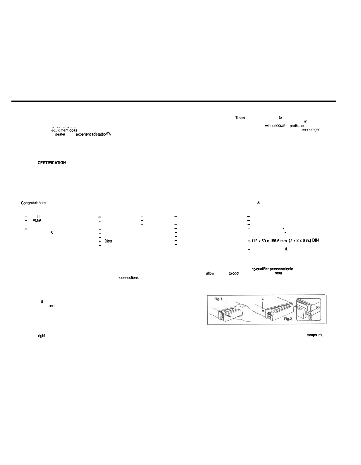
DETACHABLE FACE
Detaching & Attaching the Face:
The face of this
Detaching the Face:
Press the REL (Release) Button and detach the face by gently pulling it off as illustrated. (See Fig.1 below.)
Note: Do not pull it straight out from the chassis. Be sure not to drop the face when detaching it from the
chassis.
Attaching the Face:
Apply the
on your purchase of the Blaupunkt CD Receiver. Its Optimum Reception Control (ORC Ill) quartz FM/AM tuner Anti-Vibration
l
III
Tuner
FM/6
AM Station Presets,
Including Travelstore for all Presets
untt
can be detached and taken with you to prevent it from being stolen.
right
hand side of the face to the chassis by sliding it into the right side of the chassis. Gently push the left side of the face against the front Of the chassis Until it
CD Features
-
Track Up/Down
-
Cue/Review
-
Track Repeat
-
Track Number Indication
-
Elapsed Track Time Indication
-
DISC IN Indicator
-
1
Bitf6
Times Oversampling Digital Filter
-
Silicone-Oil Dampened Anti-Vibration
and Shock CD Mechanism
Warranty Number
connecticns
l
Audio Features:
-
Track Scan
-
Pause/Play
-
Track Mix
first. If everything is in order, check the fuse.
35 Watts (Peak) x 4 Channel
-
Integrated Amplifier
P-Channel RCA Preamp Output:
-
-
Dual-Level Fader
-
Volume/Balance/Fader Controls
-
Adjustable Turn-On Volume-Level
-
Loudness Control
Separate Bass and Treble Controls
-
allow
the Unit to
8.
Shock CD Mechanism provide the
. General Features:
-
Detachable Faceplate for Security
-
Switchable Clock/Function LCD Display
-
Ignition-Off Clock Recall
Green Illumination - RPD 435
-
Amber Illumination - RPD 435X
-
Detachable Wire Harness
176x50x155.5mm (7x2x6inJDIN
-
Chassis
-
Snap-In DIN Sleeve & Mounting Hardware
Cool
qualified peffionnel Only.
Off before Operating
yOUr
Unit.
Snaps into
Page 3

INSTALLATION
Recommendations
l
Carefully choose the mounting location so that the unit won’t interfere with normal driving.
l
Avoid mounting locations where the
excessive vibration.
l
The illustration below shows a typical installation, however, you may need to adjust the installation, depending on the unit. If you have questions or need additional installation
hardware, consult your Blaupunkt dealer.
l
Make sure the unit is firmly anchored (preferably at both front and back) and does not vibrate.
Mounting Hardware
Mounting the
You may have difficulty mounting this unit in some Japanese cars.
In this case, consult your Blaupunkt dealer.
Removing the Untt
Use the Release Keys as shown below. Keep them In a safe place In case
you need them In the future.
Fuss Replacement
When replacing the fuse, be sure to use one with the correct amperage,
which will be stated on the fuse. Never use a fuse that has a stated
amperage exceeding the one supplied for this unit, as this could cause
malfunction and serious damage to the unit,
Unft
In a
Jspaneae
SPECIFICATIONS
Audio Power
Power Output and Total Harmonic Distortton: 13.5 watts per
channel minimum continuous average output Into 4
channels driven.
total harmonic distortion.
Dther %eclflcatlona
Tuner
FM
Tuning
Intermediate Frequency:
FM Mono Sensitivity:
Seek Sensitivity
Selectivity:
Signal-to-Noise Ratio:
Harmonic Distortion at 1
Separation:
Frequency Response:
Design and specifications subject to change without notice.
Stmclflcatlona
fmm 30-15,COO
Rage
kHz:
unit
would be subject to high temperatures, such as from direct sunlight or hot air
Mounting The Untt In Most Dashboards
1 Install the Sleeve (1) in the dashboard.
2 Select and bend the appropriate tabs to hold the sleeve
3
A.
Attach the Mounting Strap (2) to the underside of the dashboard, using screw.
B.
Attach the back of the unit to the mounting strap using the support stem bolt and hardware.
Car
AM
Tunmg
Hz with no more than 1%
ohms, 4
\
675-1079MHz
67 5 106 0 MM
10.7MHz
6
dBf
22
dBf
60 dB
70 dB (stereo). 75 dB (mono)
07;B(sterec).
30-15,ooO
at 400
Hz * 0.75
IRW
435X
kHz
0.5% (mono)
dB
onlvl
Range
Seek
Sens!tiv!ty
lnlermedrate
SIgnal-to-Norse Ratlo
Audio
Speaker Impedance
MaxImum
Amp Power
RMS Power
Bass Control
Treble Control
I.
Loudness
Preamp Outputs
Preamp Output Voltage
Frequency
530-1.7lOkHz
531 -
1.502 kHz (RPD
31
dBpV
450
kHz
50
dB
4.6ohms
4x35 Watts (at 4 ohms)
4
x 17 5 Watts (at 4 ohms)
+lOdBOlOOHz
tl0 dB @
10 ktiz
tlOdB01100Hz
&+7dB@0kHz
2.CH
RCA
1.5 volts maximum 8 100%
Modulation with < 1% Total
Harmonic Distortion
Bend these tabs
435X only)
from
the heater, or where it would subject to dust, dirt or
ftnnly
in place.
Dash
(
:D Player
:innal-h-No& R&o:
*‘“;l;;; Range:
&
Frequency Response:
Harmonic Distortion: .Ol%
General
Drmensions (w/o
Mass:
Power Requirement
(neg. gmd.):
Operating Temperature:
Supplied Accessories:
projecting parts/controls):
63
dB
90dB
5-20,COO
Hz f 3 d6
620,000 Hz f 1
176x50x155.5mm
7 x 2 x 6 in.
Approx. 1.4 kg (3.0 lb.)
12 V DC car battery
15°F to 120°F. -10°C to 50°C
9
Unit
. Faceplate
l
DIN Sleeve
l
Mounting Hardware
l
Owner’s Manual in English,
French, Spanish and Portuguese
dB
I
Page 4

Note: Make sure that the
attached with gentle pressure Do not expose the face to direct sunlight, heat sources such as hot air ducts or leave it in a humid place. Never leave it on the dash board of a vehicle
parked in direct sunlight, where there may be a considerable rise in temperature inside the vehicle.
Afffxing
Faceplate For Retail Display:
The faceplate can be affixed to the unit’s chassis, which is desirable for a retail display, for example.
from behind the mounting surface. Once the faceplate is affixed, the
To
afffx
the faceplate, obtain the small bolt
the hole. (See’ rn Fig.2.)
ELECTRICAL CONNECTIONS AND INSTALLATION
@/~?#&*~@I
Carefully follow all instructions. You’ll be glad you did!
GENERAL
l
If you’re not
l
Use this unit only with negative ground 12 Volt (11-16 Volt) direct current (DC).
l
Be sure to detach the faceplate before you start to connect or
l
We recommend making and testing all electrical
To avoid the aggravation of costly
RECOMMENDATTONS
confident
ELECTRICAL
1.
&connact
2.
3.
4.
::
7
8
9
10
11
12
Once the
SPEAKER
The
tremendous
l
You can connect a speaker (regular,
speaker leads.
l
You can connect the 2 RCA preamp outputs to
systems through the amplifiers. (Blaupunkt
product brochure and/or dealer referral.)
l
You can use a combination of these two methods.
Connecting the Speaker Leads
To prevent short circuits or
l
Connect the speaker leads only as indicated in the wiring diagram.
l
Only use speakers that have impedance ratings of 4 ohms or
the head unit’s stated power level.
l
The unit’s internal amplifier is designed to handle a
l
DON’T connect two speakers to a single pair of speaker leads (“in parallel”) unless both speakers each have at least 8
ohms impedance
l
DON’T connect the left and
l
DON’T connect the front and rear speaker leads to each other or to the same speakers.
l
DON’T connect the negative speaker leads to each other.
l
DON7 connect the positive speaker leads to each other.
l
DON’T connect any active speakers (with built-in amplifiers) to the speaker leads or unless the speaker’s or amplifier’s
manual states that this is OK.
the vehicle battery’s negative terminal before making connections.
Connect the speakers and/or external amplifiers (if you have any) following the guidelines in the SPEAKER CONNECTION section below.
Connect the blue (trigger output) lead to the amplifier’s trigger input terminal and/or antenna motor trigger input terminal (if you have either or both of these Items). The combined
total amperage required for triggering the antenna motor
supply input.
Connect the black (power ground) lead to a grounded metal part on the vehicle. We recommend grounding all audio system black ground leads (head unit, external amplifier,
etc.) to a common grounding point, preferably a non-painted surface under the instrument panel.
Connect the yellow (constant power) input lead to a source of constant battery power, preferably a terminal to an appropriate slot in the fuse box.
Connect the red (turn-on power) input lead only afler the other leads are connected. Be sure to connect the red lead to a positive (+) 12 Volt power terminal that is energized only
when the ignition key is set to the on position or accessory position.
Cover the ends of any unused leads with electrical tape. This
Reconnect the vehicle’s battery.
connect me antenna
Verify that no fuses have blown.
Plug the harness into
Attach the faceplate and
connectrons
CONNECTtONS
unrt’s
Dual-Level Fader allows you to lade between the front and the rear channels using either the from and/or rear speaker leads
flexibrlity
face
is inserted right side up. Do not press against the display window. Do not press hard against the face when attaching it to the chassis, it may be easily
mlease
(M2.6~10)
from hardware pack and
mrstakes
and serious damage that could make you feel this way, please carefully read all of the instructions before you begin
drive
that you can install the unit correctly, have it installed by a qualified
mstall
the unit.
before installing the unit.
and/or
amplifier must not exceed
will
prevent them from touching the vehicle or each other and causing a short-circuit and damage lo the radio Or vehicle.
CONNECTtON
connecttons
INSTRUCTIONS
plug.
Ihe
unit.
lest
have been successfully made, you can
in configuring your speaker arrangement
the unit.
co-axral
or
td-axral
mbltiple
ampkfters
sertous
damage to the unit and/or speakers:
right
speaker leads to each other or to the same speakers.
begln
to mount the
unit
speakers or component speaker system, all hereafter referred to simply as ‘speaker”) to each of the
external amplifiers and power multiple speakers or speaker
and speakers available separately. Call l-800-950-2528
hrgher
and have power-handling capabilities greater than
4-ohm
load on each pair of speaker leads.
This
keys cannot ba used to remove the chassis.
it into the upper hole at the left of the chassis using a Phillips screwdriver. The
Blaupunkt
Connact
the leads (wires) according to instructions and diagram below.
100 mA.
should only be done in situations whom the unit can be accessed
installation
DO NOT connect the blue lead to the antenna’s
technician.
and/or
amplifier’s power
and/or
the rear preamp outputs, providing you
units’
bolt will
four pairs of
for
self-thread
Page 5

LOCATION OF CONTROLS
L_-_.
INSTRUCTIONS-GENERAL OPERATION
“Press” means momentary press ol less than
Ignition-Off Clock Recall - You can check
simply pressing the AUD Button. The time stays displayed for five seconds.
Turning Untf On -
insert
a
Turning Unit Off - Press the PWR Button to turn the unit off.
Volume - Press the + and - Buttons lo quickly increase or decrease the volume lo the
dewed level.
adfustments
disappears from the display. You can then gradually adjust the volume in either
direction. making precise adjustment easy.
Adjustable Turn-On Volume -
dewed when the
seconds. The unit turns off and the turn-on volume level is memorized. When the unit is
turned on, the volume will be at the memorized level, even it the unit was turned Ott
wh,le
the volume was at a
volume level is towe, than the sto,ed Turn-On volume level. the volume will be al the
lower level when the unit is turned back
Se,,,,,g
how bl,“k,,,q Ad,“,.,
mole 10
,e,u,n 10
Changing the Information
. To change the
pnonty changes. In the
frequency. In the CD mode, the
elapsed track
. To change the display temporarily. press and release the AUD Button one Or
times to access the desired information.’ After five seconds, the display changes back IO
the priority inlotmation.
Bass and Treble
Press AUD Button as needed lo select
level is indicated in the Display Window. Press the +
decrease the
BalanCa
Press AUD
the
Display Wmdow
sound io right.
Fader
Press AUD Button as many times as needed to select the Fader mode. The level of
output for
button to shift sound lo the front. Press - button lo shift sound to ,ea,.
.FM
the volume mode and the display
function.
dlsptay.
AU0
Button Summary
.
Press,,,g a,,,, ,c,e.,s,,,g the
.
,u,,,,,ura,y
.
P,ess,,,g the
.
Whle
/we
Vehlcte ,g”,t,o”
disc.
The
volume
to the volume level, press the other volume butlon before the volume level
t,,e
tX& -Press Ihe A”D
ad,&
the
normal mode
Butlon
Iron1
seconds alter you
You can also p,ess and release AUD as needed to
I” any AUD mode (except to, hour and minute
seconds,
level is indicated in the Display Window. To make a fine
u”,, IS
turned on Press and hold
higher
the ho”,
fhe m,nu,es also
display
pnonty. press
,ad!o
11me
level:
as needed to select the Balance
Press the +
and back speakers is indicated in the Display Window. Press the +
complete you, adtustments. the unit will
D,s,,,ay ~:f,a,,gc(s) tl.,ss
A”,,
B”,,on
,he un!, ,e,u,ns lo
the
must be on To
First
adjust the volume lo the (maxImum) volume level
level. However, it the volume is turned off when the
on.
as
many ,,mes as
“s,“g Ihe + andlo, - buflon
us,ny
,he + andlo,
Olsplayed
the
mode, the
A,,[) Bull,,”
10, I’.“”
AUD
dlsptay
display
pnonty choices are
tt)e
Bass
bunon
to
shift
wilt revert
a,:~~s~os
,,clllc.
suc”r,ds
the volume
,:ha,,~t?s. I,,”
_~___~
l/2
seconds.
lime when the vehicle ignition is off by
turn
““,t
on,
press PWR Button
the
PWR Button for more than
needed to
button
Butlo”
pnonty
cmce
sound to
back to the
~alcmco. kadc,. Il,,~,,~.
adtustmen,
access the clock with the
Press the AUD
Press AUD once
for two seconds The display
chotces are
CloCk.
more lo reach Treble mode. The
Button
0, - Bulton to increase 0,
mode
The balance IS
the
p,wity
,,,CSO ,““,,“s
dlS,,lay
adtust). 11
mode and
button once
clock and
track “umber, and
left Press - button to
automatically
display. clock 0,
return
to the priority
I”
11~2 SIIC,:USL~“”
MIIIIIIUS
p,l~,Q
no button IS pressed
prlor~ty display
0,
hvo
mole to
radio
two
mdlcated ,n
shdt
return to
NII,,,IJ
to,
Loudness
Press LO
Bu,,on 10
actwafe o, deactwe loudness
RADIO OPERATION
Automatic
Steraaono
When an FM
ste,eo indicator
and noisy. the unit automatically blends the signals, eliminating the noise and
converts to the monaural o,“mono” mode. The stereo symbol will disappear from the
Display.
Selecting the Band
Press the BND
Selactlng FM Tuning Standards: US I European (RPC 435X only)
Locate the opening on the bottom of the unit
the switch in the opening to the desired FM tuning standard as indicated by the label.
Automatic Seek Tuning
Select the desired band. Press and release the A or V butlon to
station. To stop seeking and return to the previously tuned Irequency, press the other of
the A 0, V buttons.
Manual Tuning
Select the dewed band. To
seconds. The band lndlcation blinks while the manual tuning mode is
seconds alte, you
station scan
P,ess Ihe
SCN
scan press the same butlo”
preset scan
Press the SCN button for
recewable stations for 10 seconds then returns lo the starting frequency. To end preset
scan and listen to a desired preset station, press SCN again.
Travelstore
Th,s
featwe
allows
s,a,,ons wh,ch IS espec,a,ty
S&c,
the dewed
s,a,,on
recewed
s,gnals
Once compleled, the
Selecting preset stations
S&cl
the
das,,ed
preset number wll appear
Manually Storing lndlvldual Preset Stations
1. Select the desired band using the BND button.
2. Tune in the desired frequency using seek 0, manual tuning.
3. Press and hold down the desired preset
4. The frequency blinks and the audio mutes to one second to confirm storage.
Reception Adjustment
stereo
program with a signal strength of at lea+ 50
(“a”)
appears in the Display Window. It the FM stereo program is weak
bulton
as many times as
beg,”
complete you,
Bulfon 10
ac,,“ate
more
you to
automat,ca,ty
handy when you
band
The” press
Lhe‘““,,
automat,catly
band.
P,ess
necessan/
to select the desired band.
designated wth
manual luning. press and hold the e 0, w button
ad,“s,mentS.
s,a,,on
than 2 seconds to activate preset scan. The
“n,, relums to
the desired preset button. Then the frequency
the
Tuning
scan Scanned
store 6
,ece,vabte
,,avet
BND,TS
scans. the band for the SIX stallons
to a d,“e,e”t
buflon for 2 seconds
Ihe
prewusly-tuned
button
for 2 seconds.
dBt
a label. It
s&k
Controls
,eYe,t 10
trequencles will blink
FM and 6
receivable
,ecept,on a,ea
Beg,““,“g
frequency
is tuned in, the
gadually
“ecessaly. move
the next receivable
Seek
wlh
TO
strong
fO,O
T”“,“g
Stop
unit
scans
AM
wth the last
a”d
Ihe
active. Fou,
5
COMPACT DISC OPERATION
Playing A Disc-Check Display to make sure that “DISC IN” indicator is not lit. Insert a
disc into the Disc Slot with the label sulfate facing up. “LOAD” and “DISC IN” appear in
the display. The track number and “DISC IN” indicator will appear in the Display. Play
starts at the
Do not insert a
When a CD is already in the unit, simply
playback.
Ejactlng A Disc
put in the case.
Track
number appears in the display.
Cue and Review - Press and hold the A
backward to the desired position of the track during playback.
Repeat Play - Press the RPT (Repeal Play) Bulton to repeat the same selection. The
“RPr
Mix Play - Press the MIX
will appear in the Display. To cancel, press this button again.
CD Scan -Press SCN Button to
me
10 “llll Ill” SCilll IIIOLID
Pause - Press the Pause Button
,esume play.
beginning,ot
Up/Down
indicator is displayed in the Display. To cancel. press this butlon again.
,,,,,\k,,~(l 0, Ihe
the first
selection
3.inch
CD.
-To
eject a disc, press the eject button. Once ejected, the disc should be
- Press the A Button or V Bulton to
Bullon
lrack m,mt,e,
The
(TRACK)
press
the CD Button to switch from radio lo CD
locate
the desired track. Track
Bunon
or V Button lo rapidly advance forward 0,
to play the tracks in random order. The indicator “MIX
$ta,t
CD Track Scan; start of scan mode is tndlcated by
L
N,,, stnps at cat,, ,KKk 101 111 surmrlds 1’11!!.!: d,ilJ!J
(II>)
during playback. Play will stop. Press
agaln
to
TROUBLESHOOTING GUIDE
The toltowng check wll
encounte, wllh
connect,~”
Radio
Preset
Automatic tuning Is not possible
It the above
Blaupunld
parts
you,
and
receptlo”
stations
menhoned sotuhons
dealer o, ,n the
and
sewce
as?& m
““,I
Belore
operallng
Trouble
are not receivable.
Call l-800-950-2528 lor dealer
gomg
procedures
do not help to improve the
Umled
the
co,recl,on of most
through the check
. The broadcast IS too weak
. The broadcast IS lw weak
rnil”,,R, tun,no
States call 1-800-i
problems
lkst
!66-2xx! to, technical assistance.
----
~,,a,
o, to ,e”uest
rel,
which
below.
refer
Causa/Solutlon
sltuatlon, ConSuIt
oroduct
you
back 10 lhe
-
your
may
nearest
brochure.
(
E-04
_.
.
I
Mechanical error.
?e
disc is inselted with the labeled side
,wnwards.
atched.
Eject and insert clean, undamaged disc
property (print side up).
Try
e,ect,“g and
normal
Under
qect
properly
Eject and reinsert.
remsertlng
temperature
normal temoerature cond,t,o”s.
and ,nse” clean, undamaged disc
condthons
I
under
1
 Loading...