

Page 1
AUTORADIO
Schaltbild • Circuit diagram
PSA RD4 LEVEL2
BASIC
7 643 141 392
PSA RD4 LEVEL2
Japan MP3
7 643 142 392
PSA RD4 LEVEL2
MP3
7 643 143 392
8 622 403 856 BN-ST 08/03
CLASS 1
LASER PRODUCT
D
VORSICHT!
Die Geräte beinhalten eine Laserkomponente!
Im Servicefall bitte nachfolgende Hinweise
beachten:
• Das Gerät arbeitet mit unsichtbarem Laserstrahl.
• Bei geöffnetem Gerät tritt im Bereich des Plattenfaches
Laserstrahlung aus.
• Nicht in den Strahl blicken.
• Unbeteiligte Personen vom Arbeitsplatz fernhalten.
• Der Betrachtungsabstand darf 13 cm nicht unterschreiten.
• Kann dies nicht eingehalten werden, muß eine geeignete
Laserschutzbrille getragen werden.
Inhaltsverzeichnis / Table of contents
Inhaltsverzeichnis...................................................1
Schaltbild Hauptplatte 9094 D05
Blockschaltbild ..................................................2
Endstufe............................................................3
Antennen...........................................................4
Schnittstelle.......................................................5
MPX Signal Prozessor ZF DCR3A ..................6
Hauptprozessor.................................................7
NF-Teil...............................................................8
MP3...................................................................9
Spannungsversorgung ....................................11
NF-Prozessor ( DCR4 )...................................10
Layout Hauptplatte 9094 D05 .......................12 - 14
Schaltbild Schalterplatte 9095 D05......................17
Layout Schalterplatte 9095 D05 ..........................18
Schaltbild CD-Laufwerk BP7................................19
Layout CD-Laufwerk BP7.....................................20
Schaltbild Anschlußplatte 9096 D02 ....................21
Layout Anschlußplatte 9096 D02.........................22
UNSICHTBARE LASERSTRAHLUNG
NICHT DEM STRAHL AUSSETZEN
LASERKLASSE 3B
GB
CAUTION!
The CD units are equipped with a laser component!
For servicing make sure to observe the following
instructions:
• The unit operates with invisible laser beams.
• When the cover is removed, invisible laser beams are
emitted near the disc compartment.
•Avoid direct eye contact with these beams.
• Keep unauthorised persons away from the workbench.
• The viewing distance should not be less than 13 cm.
• If this distance cannot be kept, use suitable laser safety
goggles.
Ta ble of Contents ...................................................1
Circuit diagram Main board 9094 D05
Block diagram ...................................................2
AF output ..........................................................3
Antenna.............................................................4
Interface............................................................5
MPX signal processor IF DCR3A.....................6
Main processor .................................................7
AF section.........................................................8
MP3...................................................................9
Power supply...................................................11
AF processor ( DCR4 ) ...................................10
Layout Main board 9094 D05........................12 - 14
Circuit diagram Key board 9095 D05...................17
Layout Key board 9095 D05 ................................18
Circuit diagram CD mechanism BP7....................19
Layout CD mechanism BP7.................................20
Circuit diagram Connector board 9096 D02 .......21
Layout Connector board 9096 D02.....................22
Page 2
HAUPTPLATTE
MAIN BOARD
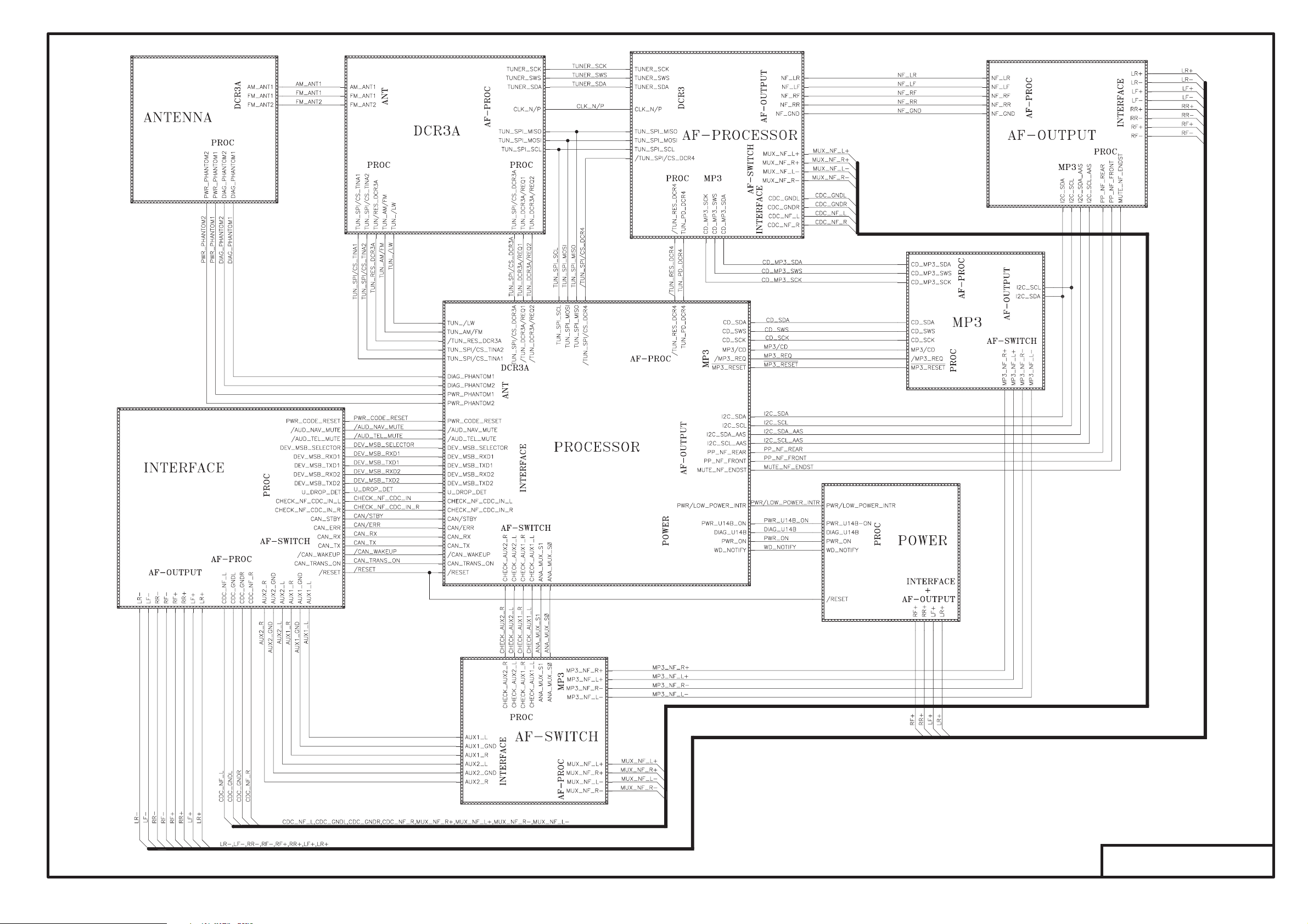
Blockschaltbild
Block diagram
PL 9094 D05
Page 3
HAUPTPLATTE
MAIN BOARD
NF-Prozessor
AF-Processor
( DCR4 )
PL 9094 D05
Page 4
HAUPTPLATTE
MAIN BOARD
Endstufe
AF output
PL 9094 D05
Page 5

HAUPTPLATTE
MAIN BOARD
Antennen
Antenna
PL 9094 D05
Page 6

HAUPTPLATTE
MAIN BOARD
Schnittstelle
Interface
PL 9094 D05
Page 7

HAUPTPLATTE
MAIN BOARD
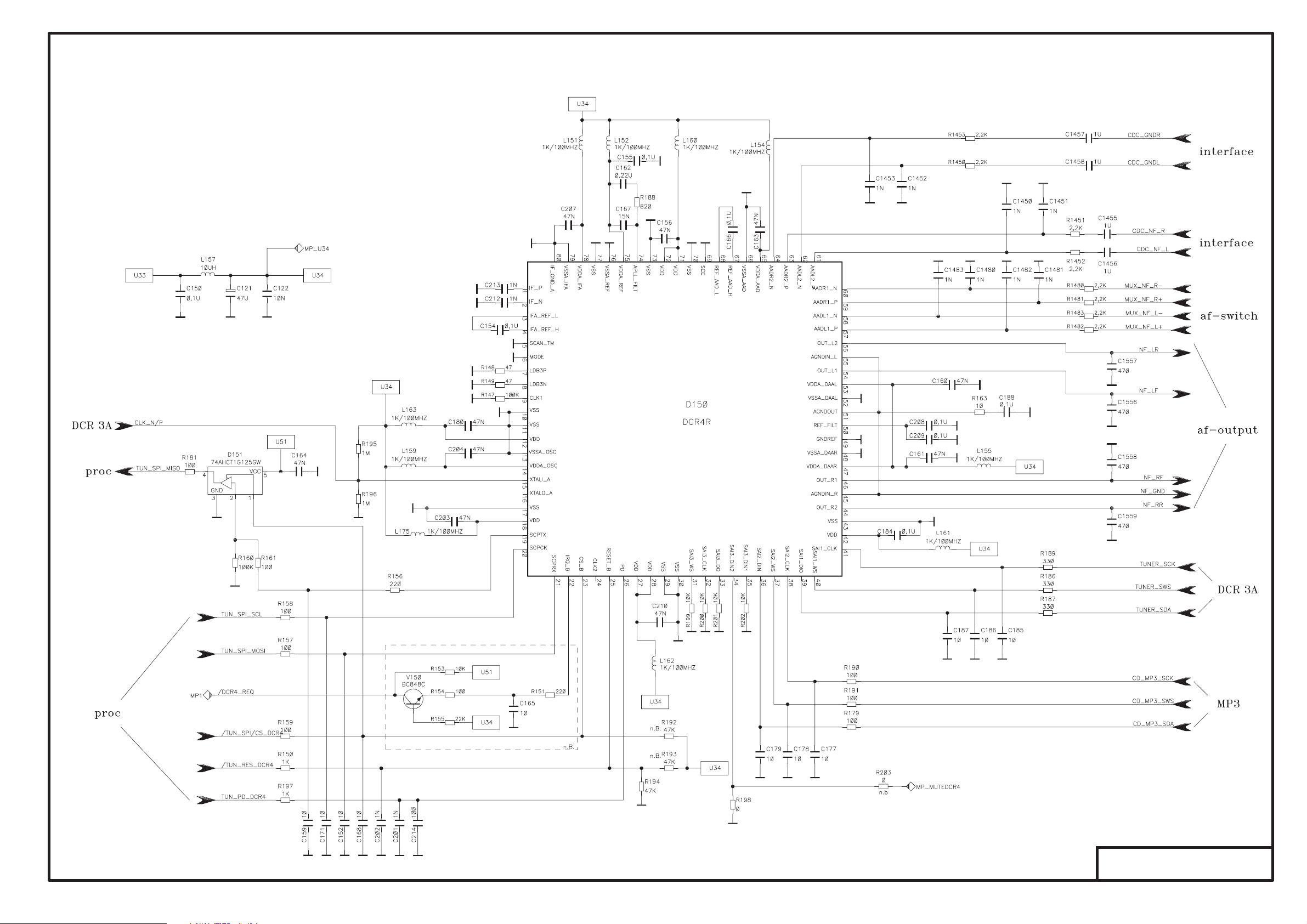
MPX Signal Prozessor
MPX signal processor
ZF DCR3A
IF DCR3A
*) Wird nicht best ckt
*) Would not be inserted
PL 9094 D05
Page 8

HAUPTPLATTE
Hauptprozessor
Main processor
MAIN BOARD
PL 9094 D05
Page 9

HAUPTPLATTE
MAIN BOARD
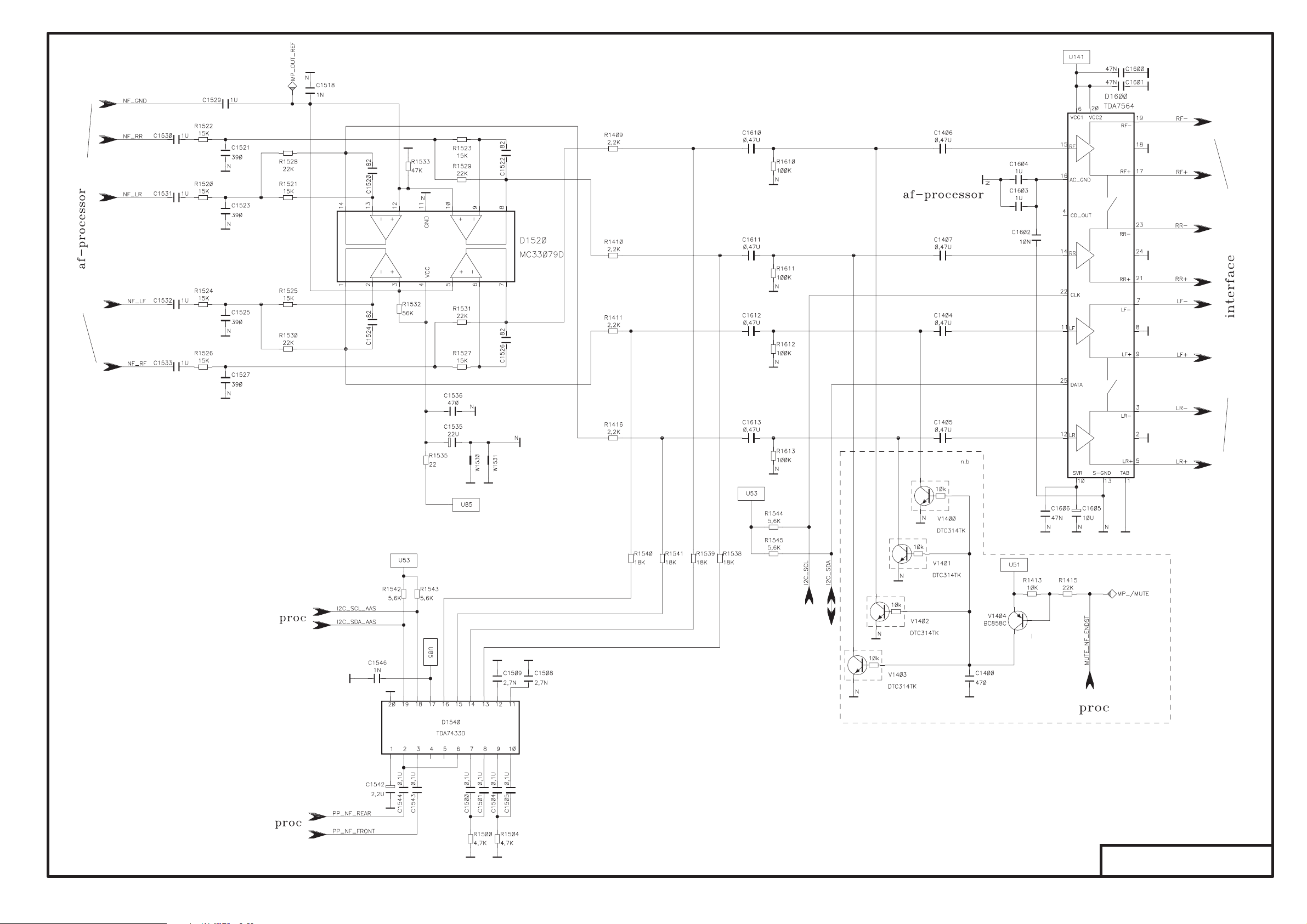
NF-Teil
AF section
PL 9094 D05
Page 10

HAUPTPLATTE
MAIN BOARD
MP3
PL 9094 D05
Page 11

HAUPTPLATTE
MAIN BOARD
Spannungsversorgung
Power supply
PL 9094 D05
Page 12

LED-ID
LOT670K2
AUDIO SOURCE
H3303
TRIP
H3302
LOT670K2
R3302
1K
V3303
BC848C
R3303
180
H3307
LOT670K2
H3306
LOT670K2
BAND
H3308
LOT670K2
DARKCLIM
R3304
1K 1K
V3305
BC848C
R3305
180
H3309
LOT670K2
ESC
H3304
LOT670K2
MENU
H3321 H3316
LOT670K2
TONE
R3306
V3307
BC848C
R3307
180
H3322H3305
LOT670K2
OK EJECT
H3311
LOT670K2
<<
H3312
LOT670K2
|<
R3308
1K
V3309
BC848C
R3309
180
H3301
LOT670K2
H3310
LOT670K2
|<
H3315
LOT670K2
>> PTY
R3310
1K
V3311
BC848C
R3311
180
LIST
R3312
1K
H3313
LOT670K2
TA
H3314
LOT670K2LOT670K2
LOT670K2
H3323
LOT670K2
12
H3318
LOT670K2
H3320
LOT670K2
56
R3314
V3313
BC848C BC848C
R3313
180
1K
V3315
R3315
180
R3316
1K
H3317
LOT670K2
H3319
LOT670K2
43
H3324
LOT670K2
V3317
BC848C
R3317
180
R3321 150k
R3322 47k
R3323 0
J2
K1
K2
R3301 47k
ID-Platte
X3301
1
2
3
DIM_KEYS_PWM_OUT
4
U141
5
LED-DETECT
6
KBD_X0
7
KBD_0X
8
KBD_1X
9
KBD_2X
10
KBD_3X
11
KBD_4X
12
KBD_X1
13
KBD_X2
14
KBD_X3
15
KBD_X4
16
HMI_ENC2
17
HMI_ENC1
18
CAP_DETECT
19
PWR_ON_KEY
20
R3329
5,6K
Iluminationclass
R3321/22/23
R3321
R3322
R3323
nb.
n.b.
150 kohm
47 kohm
0 ohm
J1
J2
K1
K2
9583
9582
9581
9580
R3318
1K
LOT670K2
H3300
CORONA
R3324
150
R3325
150
V3319
BC848C
R3319
180
STROBE 0
STROBE 1
STROBE 2
STROBE 3
STROBE 4
EJECT
CLIM
TRIP
MENU
S3301_1
S3301
S3302_1
S3302
S3303_1
S3303
S3304_1
S3304
AUDIO
BAND
SOURCE
DARK
TONE
SCAN 0
S3305_1
S3305
ESC
S3306_1
S3306
|<
S3307_1
S3307
<<
S3308_1
S3308
|<
S3321_1
S3321 S3322
OK
S3309_1
S3309
S3310-1
S3310
S3311_1
S3311
S3312_1
S3312
S3322_1 S3323_1
SCAN 1
TA
LIST
>>
PTY
PWR_ON_KEY / VOLUME
S3300
45
COMS
AB
DM1
1
DM2
1
6
1
2
7
DataMatrixCode
DataMatrixCode
SCAN 2
S3313_1
S3313
S3314_1
S3314
S3315_1
S3315
S3316_1
S3316
4
2
5
3
SCAN 3
S3317_1
S3317
S3318_1
S3318
S3319_1
S3319
S3320_1
S3320
SCAN 4
3
EVEVOOPF516B
S3324_1
1
S3323
6
S3324
SCHALTERPLATTE
KEY BOARD
PL 9095 D05
Page 13

ANSCHLUSSPLATTE
CONNECTOR BOARD
PL 9096 D02
 Loading...