

Page 1

Page 2
2
Page 3

Dispiay
The display consists of three fields and changes according to the operating mode and function.
.“‘-*%w:w\
y_.
lj i
\a,*”
Display field 1:
Radio mode
Memory banks and wavebands
Brief indication of preset station (e.g.
Pl)
Cassette mode
CAS - cassette inserted
Chanaer mode (Chanaer sold separately)
Current track
Numeric and graphic representation of the
volume and audio settings.
Indicates DSC mode is active.
Graphic representation of the adjusted
volume level.
Display field 2:
Radio mode
Radio frequency or station name
Clock display
Cassette mode
TAPEl/TAPE2 -
side of tape being played.
Displays active function.
Clock display
Chanaer mode (Chanaer sold seoaratelv)
CD number being played by changer.
CD time (elapsed time)
Brief indication of functional changes
Clock display
Serves as display and entry field during DSC
programming
Miscellaneous
indicates new source (e.g. when changing
from radio to cassette)
Display field 3:
Displays active functions.
-
Stereo
CT,
-
Cassette inserted
Disc
-
CD changer connected
E -
Loudness
Radio mode
-
Seek tuning sensitivity
lo
Chanaer mode (Changer sold separately)
RPT - Repeat function
MIX - Tracks played at random
3
Page 4

c-
Contents
Display
Quick reference
Important notes
What you
Traffic safety
Installation
Accessories
Warning
Detachable
Theft protection
Affixing the detachable face
Selecting the audio
Radio
Selecting a waveband
Station
Automatic seek tuning
Manual tuning with
Switching between the
memory banks (FM)
Storing stations..................................... IO
Recalling
Scanning stations with Preset Scan..
Scanning stations with Radio Scan..
Changing the scan time..
............................................
..............................
..............................
needtoknow
...........................................
..............................................
.
............................................
note
..........................................
face
.......................................
..........................
.............................
...................
source..
operation
tuning..
....................................
..........................
......................................
A/V
..............
..................
<c
>>
.............................
stored stations ......................
......................
.........
...
....
Automatically storing the
3
strongest stations with Travelstore..
Naming radio stations ...........................
5
Deleting radio station names
8
Deleting a radio station name
Deleting all of the radio station names1 2
8
Setting the TIMER ................................
8
8
Cassette
8
Cassette playback
8
Cassette eject
8
Fast winding..
Reversing
8
9
CD changer operation (optional) 14
9
Inserting
Switching to the CD changer mode
IO
Ejecting a CD..
10
CD
10
Selecting a
10
Selecting
10
SCAN
RPT
10
MIX..
IO’
CLOCK/Display
11
Setting the clock ...................................
11
Turn
11
a
playback .........................................
....................................................
.......................................................
......................................................
On
operation
deck
................................
.......................................
........................................
the tape ...............................
CD.......................................
......................................
CD......................................
a
track ...................................
changes..
Message..
................
...........
.............
...........
.......................
.....
......
DSC
programming
11
Overview of the DSC factory settings . . 18
11
Appendix
12
Specifications.. ......................................
12
Amplifier
Tuner
13
13
13
Cassette
CD changer (sold separately)
Troubleshooting
13
General
13
Radio reception
13
CD
Error Displays
14
14
14
14
14
14
15
15
15
.......................................
............................................
.................................................
............................................
.................................................
Changer operation..........................
.......................
Guide
....................................
.......................................
...............
15
16
16
...........
16
18
18
18
18
18
18
19
19
19
19
20
4
Page 5
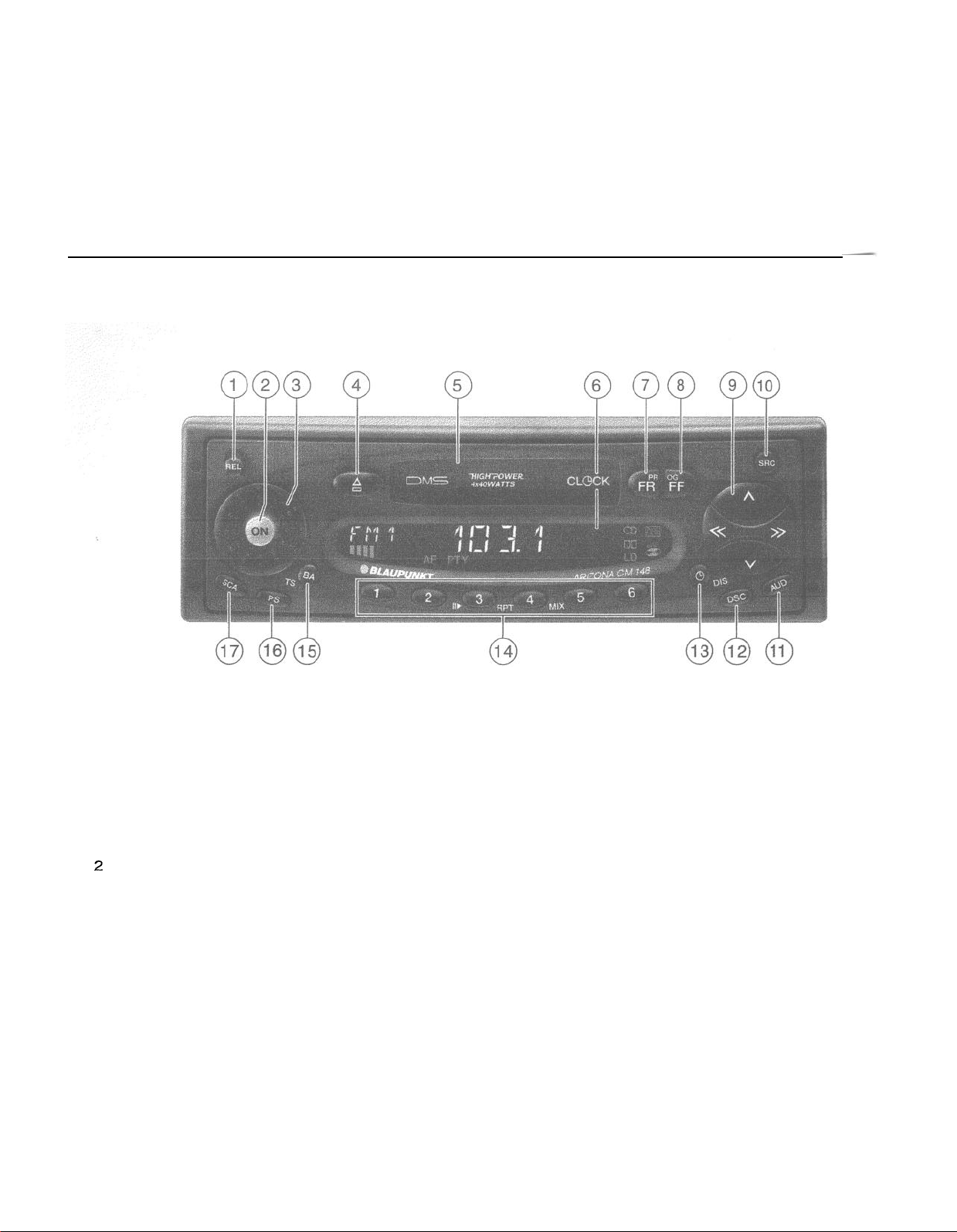
Quick reference
@
REL
To release the detachable face, press
this knob and remove the
detachable face.
@
ON - Power up/down
Press this button to turn the unit on. It
will play at the volume set under DSC.
Mute: If you press this button briefly
during radio reception, the volume will
turn down instantly.
This function is cancelled by pressing
the ON button again. You can
programme the mute volume (refer to
“DSC programming”).
Press the button for about 1 second to
turn the unit off.
Switching on/off via the ignition:
If the unit has been connected
correspondingly, it can also be turned
on and off with the vehicle ignition.
If ON is pressed while no power is
being supplied to the red (ignition)
lead, the unit will automatically turn off
after one hour. This prevents the
battery from going dead.
@Volume knob
Turn the knob to set the volume.
@ P
Eject
Press this button to eject the cassette.
The cassette buttons will retract.
@
Cassette slot
Insert the tape into the slot with the
open side showing to the right. The
tape will be played in the direction
previously selected.
@
Display
Displays all settings, operating modes
and functions.
@
FR Fast Rewind
To fast rewind the tape.
@
FF Fast Forward
To fast forward the tape.
@
+ @) Reversing the tape (PROG)
Press both buttons simultaneously.
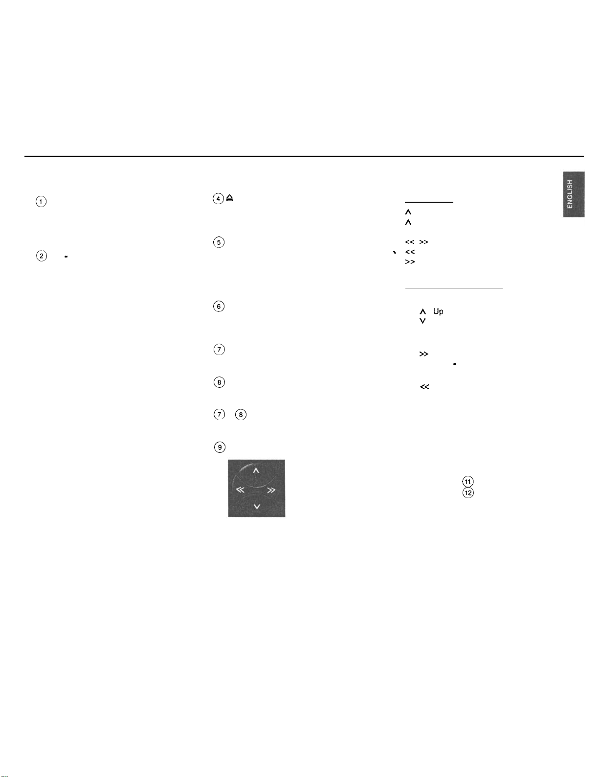
@
Rocker switch
Radio mode
A I V
Seek tuning
A
UP
V
Down
cc
I
z->
. <<
Manual tuning
Up in short intervals
>>
Down in short intervals
Changer mode (optional)
Select CD
A UP
V
Down
Select track
>>
Up: press briefly
CUE - fast forward (audible):
button down.
c<
Down: press two or more times
briefly
Repeat track:
REVIEW -fast
hold
button down.
press briefly.
reverse (audible):
Extra function of rocker switch:
The rocker is also used in these
modes
AUD mode
DSC mode 12
11
8
Requirement: The respective function
must be activated.
hold
5
Page 6
@ SRC
(SRC = audio source)
Press button briefly to select the
operating mode (tuner, cassette,
changer or Aux-in). The active mode
appears in the display.
11
AUD
0
You can store different treble and bass
settings for the FM, AM, cassette and
CD changer or Aux-in modes.
Setting the tone:
Select the audio mode. Press AUD
once and set the tone using the rocker
switch.
Treble:
A
Treble +
V
Treble
-
Bass:
c<
Bass-
>>
Bass +
Press AUD twice and set the fader and
the balance using the rocker switch.
A Fader front
V
Fader rear
x-z
Balance left
>>
Balance right
The selected values will appear in the
display. The last setting is stored
automatically.
6
Switching AUD off
Press button briefly.
If you do not change the tone within
8 sec., the AUD mode will quit
automatically.
Extra function: LD
Loudness boosts the bass frequency
at low volume.
Press AUD longer than 2 seconds to
change the Loudness setting. “LD” will
appear.
The loudness level is set under DSC.
@
DSC Direct Software Control
Adjusts programmable settings.
Refer to “DSC programming”.
@
(9
DIS
- clock display
This unit is equipped with an internal
clock.
priorityDisplay
To alter the display priority, press
until you hear a beep. Repeat this
procedure until the desired display
,
appears.
Temporary display change
Press 0 briefly as many times as
needed to show the desired
information for a few seconds.
Radio mode
Press this button to switch between the
clock, the station name and the
frequency.
Cassette mode
Press this button to switch between the
track played and the clock.
Chanaer mode (optional)
Press this button to switch the display
of the CD number, the playback time
elapsed and the clock.
@
Preset buttons 1 to 6
Radio mode
You can store six stations in each FM
memory bank
(1,2,
and
‘7”).
On AM you can store six stations.
Store station - hold down a preset
button in radio mode until a beep is
(9
emitted.
Recall station - select a waveband
and also the memory bank on FM;
press the relevant preset button briefly.
The selected preset button will briefly
appear in display field 1 (e.g.
Pl).
Page 7
Changer mode (optional)
3/W - Pause
interrupts CD play. “PAUSE” appears.
Press button again to restart CD play.
4lRPT
Repeat track: press
T”
appears briefly. The track will be
repeated until
4IRPT.
WRPT
is pressed again.
“REPEAT-
Repeat CD: select “REPEAT-D”.
Switch REPEAT-D on:
l Hold URPT down until a beep is
emitted.
5/MIX
“MIX CD” plays the tracks of one CD in
random order.
“MIX ALL” plays the tracks of all CDs
of one changer magazine in random
order (as determind by the changer
model).
To turn MIX on/off:
Press 5/MIX briefly.
The current setting is briefly indicated
in the display: “MIX-CD”.
Switch MIX-ALL on:
l Hold 5/MIX down until a beep is
emitted.
@
BAITS
Switches between the wavebands/
memory
(Travelstore,
-~-
banks
FMl, FMZ,
^_^\ ^^^I AL.
ark WI.
FMT
Extra function: Travelstore
To store the six most powerful FM or
AM stations in the Travelstore bank:
Select FM or AM by pressing
Press
BAITS
until a beep sounds and
“T-STORE” appears.
@
PS - Preset Scan
Press PS briefly. All currently-
receivable stored stations will be
scanned.
To stop Preset Scan, press PS again.
(Use DSC to set the Scantime.)
@
SCA
Press SCA to select the SCAN
function. Use DSC programming to set
the scantime.
Press SCA to stop SCAN function.
Radio mode
Press SCA.
The radio will scan all receivable FM or
AM stations. “SCAN” and the station
appear on the display on after another.
BAITS.
Changer mode (optional)
F
‘ress
SCA.
“SCAN” will be displayed. All tracks of
the CD will be scanned.
,
7
Page 8
Important notes
Detachable face
What you need to know
Before using your new car radio, please read
through the following information carefully.
Traffic safety
As the driver of a motor vehicle, it is your
responsibility to pay attention to the traffic
situation at all times.
Never use your car radio in a way that could
distract you.
Please keep in mind that you travel a
distance of 15 yards per second at a speed
of only 30 mph.
Should the traffic situation become
particularly demanding, we advise you not
to use the radio.
Always make sure that you are still able to
hear any warning signals coming from
outside the vehicle, such as police or fire
engine sirens, so that you can react
accordingly.
Consequently, you should always select a
moderate volume for playing your car radio
while you are driving.
Installation
If you would like to install your new car radio
yourself or add other audio components to
existing ones, please read the enclosed
instructions on installation and connection
carefully.
In order to ensure that the unit operates
properly the positive power supply line must
be connected via the ignition and the
permanent +I 2 V lead.
Do not ground the loudspeaker outputs!
Accessories
Use Blaupunkt-approved accessories and
spare parts only.
Changer
(not included with the unit, sold separately)
CDC-A08
CDGA071
CDC-A05 (with adapter only)
!
Warning note
A
Danger of damaging the automatic
power antenna in a car wash
Before you drive into a car wash
l
switch the radio off by pressing the ON
.
button.
The power antenna will retract, if it
doesn’t, press ON again.
Do
not drive into the car wash unless the
power antenna has retracted!
Theft protection
This unit is equipped with a detachable face.
A car radio without face is worthless for
thieves.
Protect your car radio and detach the face
when you leave your car. It is very easy to
attach and detach the detachable face.
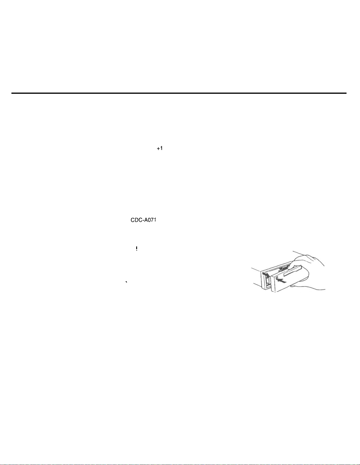
Note:
Do not pull the detachable face straight out
from the chassis, but detach it as illustrated
below. Be sure not to drop the panel.
Do not expose the detachable face to direct
sunlight or other heat sources.
Do not leave it in a humid place.
Detaching the detachable face
Press the REL button to release the control
panel. Then pull it off gently as illustrated.
8
Page 9
Selecting the audio source
If the unit was still in operation, it will turn
off now. All current settings remain stored.
If a cassette is inserted, it will be kept in the
unit.
The radio will turn on automatically when
you attach the detachable face again.
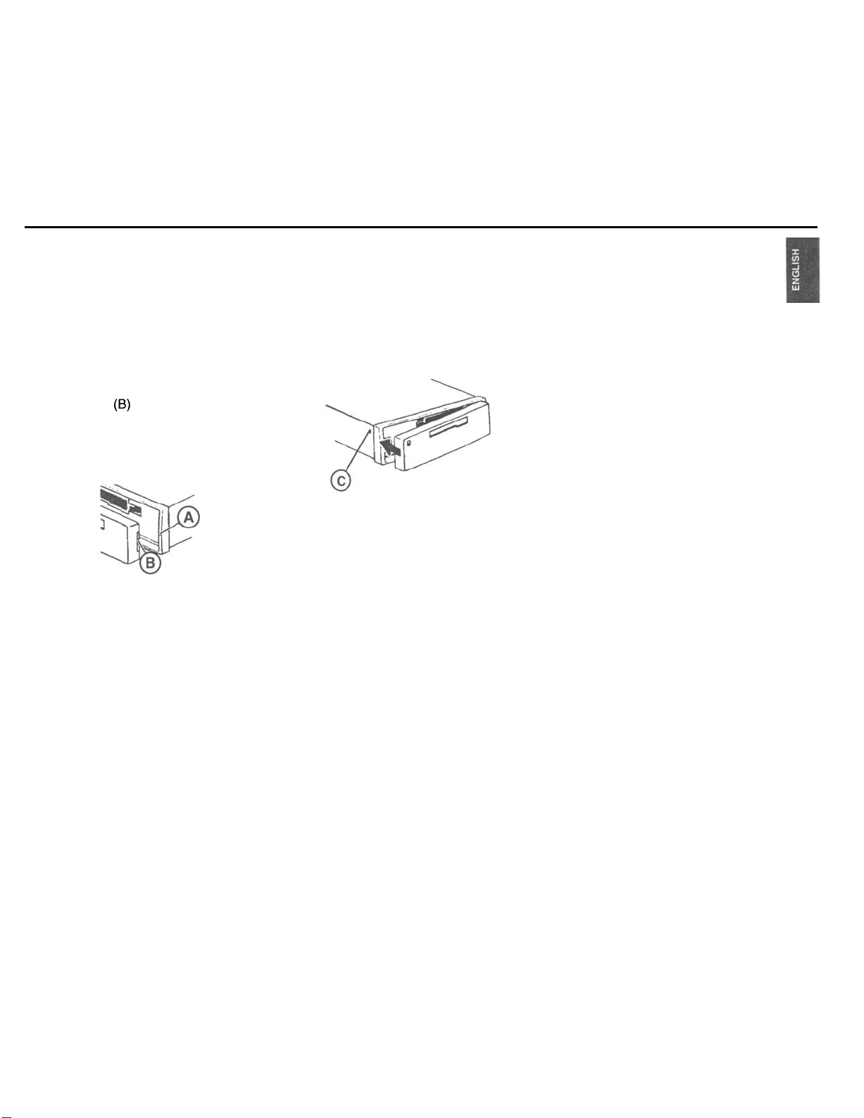
Attaching the detachable face
Slide the panel (6) from the left to the guide
of the chassis (A). Gently push the left side
of the panel against the front of the chassis
until it snaps into place.
Affixing the detachable face
If you wish to fix the detachable face
permanently to the chassis, screw down the
enclosed bolt at the left hand side of the
chassis into the hole (C), see Fig.
Use the SRC (source) button to select
between radio, cassette and CD or Aux-in
mode.
The CD mode is not available unless a CD
changer is connected.
The Aux-in mode is available if a changer is
not connected. (See DSC programming.)
To select the operating mode:
l Press SRC.
Page 10

Radio operation
Selecting a waveband
With this car radio you can select between
the following wavebands:
FM 87.5 - 107.9 MHz
AM 530 - 1710
Select the desired waveband by
l
pressing the BAITS button.
Station tuning
Automatic seek tuning
Press A or V; the car radio will
l
automatically search for the next
station.
If you hold
rocker switch, seek tuning will speed up in
the upwards or downwards direction.
Automatic seek tuning
A
UP
V Down
kHz
NV
A/V
pressed up or down on the
Manual tuning with <<
>>
You can also tune into a station manually.
l Press
<< >z-;
the frequency will change
in short intervals in the downwards or
upwards direction.
If you hold << >> pressed to the left or the
right on the rocker switch, the frequency
scan will speed up.
Switching between the memory
banks (FM)
You can switch between the memory banks
FM1 ,
FM2 and FMT in order to store stations
and recall them later.
The currently selected memory bank
appears in the display.
l Press the BA/TS button as many times
as necessary until the desired memory
bank lights up in the display.
Storing stations
On FM, you can store six stations on the
preset buttons
.
memory banks
You can also store six stations on AM.
l
Select the waveband by pressing
BAITS.
1,2,3,4,5,6
(FMI,
FM2, FMT).
for each of the
l
Tune into a station with the rocker
switch (either automatically A/V or
manually CC
l Press the desired preset button until
2~).
the radio resumes play after the
muting (takes approximately 2
seconds) or until you hear a beep.
Now the station has been stored.
The display will temporarily indicate which
preset button is currently activated.
Recalling stored stations
You can recall any stored station at the touch
of a button.
l Select the waveband by pressing
BMS. For FM, also choose the
corresponding memory bank by
pressing the
times as necessary until the desired
bank appears in the display.
l Press the corresponding preset button
briefly to recall the station.
BA/TS
button as many
10
Page 11

Scanning stations with
Preset Scan
You can scan all of the radio stations on AM
or FM.
The scanned stations of the current
waveband will appear briefly one after the
other in the display.
Start Preset Scan:
l Press PS briefly.
“PS-Scan” and the station name or
frequency will appear alternately in the
display. The abbreviation for the station
currently playing (e.g.
Pl)
will flash in display
field 1
Listen to scanned station/end Preset
Scan:
l Press PS briefly.
Scanning stations with
Radio Scan
You can scan through all of the stations in
your reception area.
To start the Scan function:
l Press SCA briefly.
The scanned frequency or the station name
will start flashing in the display.
During the actual scanning process “SCAN”
will appear in the display.
Listen to scanned station/end Radio
Scan:
l Press SCA briefly.
Changing the scan time
The scan time can be selected from between
5 to a maximum of 20 seconds.
If you would like to alter the scan time,
please refer to the section on “DSC
programming - SCANTIME”.
Selecting the automatic tuning
sensitivity
You can alter the automatic tuning
sensitivity.
If “lo” is displayed, the radio will only pick up
strong, local stations (low sensitivity).
If “lo” does not light up, the radio will also
pick up weaker, more distant stations (high
sensitivity).
If you would like to alter the sensitivity level
please refer to the section on “DSC
programming -
SENS”.
Automatically storing the
strongest stations with
Travelstore
You can automatically store the six FM /AM
stations with the most powerful signals in
your current reception area sorted according
to their signal strength. This function is
particularly convenient on longer trips.
Press the BAITS button to select the
waveband.
l Press the
BMS
button for 2 seconds.
“T-STORE” will appear in the display.
The six strongest FM stations will be
automatically stored in the “FMT” memory
bank (Travelstore).
If the AM band is active, the six strongest
AM stations will be automatically stored in
the AM memory bank.
When this process has been completed, the
radio will play the strongest station.
If desired, stations can also be stored
manually in the Travelstore bank (see
“Storing stations”).
Naming radio stations
To enable you to pick out your favorite radio
station more quickly, DSC programming
allows you to give up to 30 radio stations
individual names.
11
Page 12

The radio station does not have to be stored
in the memory bank. The names are linked
to the radio frequencies.
Proceed as follows:
Select the DSC mode.
l Press DSC.
Press A I v to select STA-NAME.
l
Press
c-z >>
l
to switch to the station-
select mode.
Press A Iv to select the station you
l
would like to name.
Press <c >> to confirm your selection.
l
Now you are in the edit mode. If the
l
station selected does not have a
name, 8 dashes
I‘_”
will appear in the
display.
The cursor will flash at the current
l
position. Press <c >> to move the
cursor.
Press A / v to select a character. If you
l
want to enter a blank, select the dash
II ,,
_.
Press DSC to store the name. Press
l
DSC again to quit the DSC mode or
’
press << >> to re-enter the stationselect mode.
If you want to change the name, select the
name in the DSC mode and overwrite it in
the edit mode.
If you want to change just a few of the letters,
Deleting all of the radio station names
press << >> to move the cursor to the Select the
corresponding position and change only that
character.
Deleting radio station names
Deleting a radio station name
Select the DSC mode.
Press DSC.
Press A / v to select STA-NAME.
Press <c >> to enter the station select
mode.
Press A /v to select the name you
want to delete.
Press and hold down DSC.
“ONE NAME” will appear in the
_
Press DSC.
.
Press A
.
Press <c
mode.
.
Press and hold down DSC for
8 seconds.
.
After 2 seconds and 8 seconds you will
hear a beep. “ONE NAME” will appear
first in the display, followed by
“ALLNAMES”
l
Release DSC. “DELETED” will appear
in the display. All of the station names
have been deleted. The unit will switch
back to DSC mode.
display.
Release the DSC button after
2 seconds but before 8 seconds.
“DELETED” will appear in the display.
The station name has been deleted.
The unit will switch back to DSC mode.
DSC mode
/
v to select STA-NAME.
z=>
to enter the station select
12
Page 13

Cassette deck operation-
Setting the TIMER
Using this unit it is possible to conveniently
switch on any two radio stations you select
at any time you select. The radio stations
can be selected independently of the
currently active operating mode.
Proceed as follows:
Select the radio station of your choice.
Press DSC.
Press
h/v
to select TIMER 1.
Press >> to turn the TIMER on. (Press
<<
to turn the TIMER off.).
Press >> again to select time display.
The minutes will flash.
Press A / v to set the minutes.
Press << to activate the hours.
Press A / v to set the hours.
Press DSC to store your entry. You
have now set TIMER 1.
If you would like to set TIMER 2 as well,
repeat the steps as described above.
Note
The timers can be turned on and off while
any audio source is in use.
Cassette playback
Insert the tape into the slot with the open
side showing to the right.
The cassette playback will start. If a tape is
already inserted, press SRC to select the
tape deck mode.
appear. The tape will be played in the
direction previously selected.
“TAPEl”
or “TAPE2 will
Cassette eject
Press P to eject the cassette. The cassette
buttons will automatically retract.
Fast winding
Press the FF or FR button to fast forward or
rewind the tape during cassette operation:
“FORWARD” or “REWIND” will light up in
the display.
When the end of the tape is reached with
fast forward, the tape direction will change
and the other side of the tape will played.
With “Radio Monitor ON” during fast winding
you can listen to the radio program you
selected previously. It is possible to change
the Radio Monitor on/off setting in the DSC
mode. (Refer to “DSC programming - RM”.)
Reversing the tape
To change the tape direction during cassette
playback:
l
Press
FR/FF
simultaneously.
Tke display shows
the selected tape side.
“TAPEl”,or
“TAPE2” for
13
Page 14

CD changer operation (optional)
This unit offers you the ability to conveniently
control a Blaupunkt CDC-A08 or CDC-A071
changer (or CDC-A05 with a special
adapter), all sold separately.
If a CD changer is connected, the
c%%
symbol will light up in the display.
The changer is equipped with a magazine
for 10 discs.
Inserting a CD
Insert one or several CDs into the magazine
(printed surface facing up).
Slide the magazine into the CD changer in
the direction of the arrow.
The CDs are counted from bottom to top.
Note:
Use only perfectly circular CDs with a
diameter of 12 cm!
CDs with a diameter of 8 cm or CDs manu-
factured in the shape of a mug, for example,
are not suitable for use with this equipment.
Using such CDs can very likely result in the
destruction of the CD and the CD drive.
We assume no responsibility for damages
caused by using unsuitable CDs.
After you have inserted the magazine, keep
the door of the magazine closed to prevent
contamination.
14
t
Switching to the CD changer
mode
Make sure that at least one CD has been
inserted into the magazine.
Press SRC to change the audio source:
l Press SRC repeatedly until the CD
functions appear in the display.
Ejecting a CD
Open the door of the CD changer and press
the eject button.
CD playback
Press
SIX
to select the CD changer.
l Press SRC repeatedly until
“CHANGER” appears in the display.
CD playback starts with the first CD
identified by the changer.
Selecting a CD
When CD playback starts, all active CD
functions and the CD number will light up in
the display.
To change the display between CD number
and elapsed time, press 0 during CD
playback.
h
I v CD selection
A UP
V
Down
The CD number being played will appear
in the display.
Selecting a track
>>
Up: Press briefly.
CUE
-
fast advance (audible):
Hold button down.
Down: Press two or more times briefly.
<<
To re-start a track: Press briefly.
(When at start of first track, unit goes to
last track on same disc.)
REVIEW - fast reverse (audible):
Hold button down.
Press the button repeatedly to skip several
tracks.
The number of the selected track will appear
beside
“T”
(track).
Page 15

CLOCK/Display changes
SCAN
Use this function to scan all of the CD tracks.
To start the Scan function:
l Hold down SCA until “SCAN” appears.
All of the CD tracks will be scanned one after
the other in ascending order.
To stop the Scan function:
l Press SCA briefly.
The track currently scanned will continue to
play.
The SCAN function will also be cancelled
by pressing any other button, except for the
volume controls and the AUD and ON
buttons.
RPT
CD tracks can be played repeatedly.
The following options are possible:
-
Repeat the current track (“REPEAT-T”)
or
-
Repeat the CD, i.e. all tracks of the
current disc (“REPEAT-D”).
“RPT” will appear in display field 3 as long
as RPT is active.
“REPEAT-T” lights up briefly in display
field 2 when you activate this function and
each time the track changes.
Switch REPEAT-T on:
l Press
WRPT
briefly.
Switch REPEAT-D on:
l Hold 4/RPT down until a beep is
emitted.
MIX
You can have the CD tracks played in
random order.
The following options are possible:
-
Mix all tracks of one CD (“MIX-CD”)
or
-
Mix all tracks of all CDs (“MIX-ALL”) in
manner determined by the CD changer
model.
“MIX” will appear in display field 3 as long
as the MIX function is active.
“MIX-CD” lights up briefly in display field 2
when you activate this function and each
time the track changes.
Switch MIX-CD on:
l Press 5/MIX briefly.
Switch MIX-ALL on:
l Hold 5/MIX down until a beep is
emitted.
This unit is equipped with an internal clock.
Disolay priority
To alter the display priority, press
until
you hear a beep. Repeat this procedure until
the desired display appears.
Temporary display chanae
’
briefly as many times as needed
Press
to show the desired information for a few
seconds.
Radio mode
Press to switch between the clock, the
station name and the frequency.
Cassette mode
1
Press
to switch between the track played
and the clock.
Changer mode (optional)
Press to switch the display of the CD
number, the playback time elapsed and the
clock.
15
Page 16
Turn On Message
DSC programming
Setting the clock
Set the clock in the DSC mode.
l Press DSC briefly.
Press A I v to select the function
l
“CLOCKSEP.
l Press
l
l
l
-z-z >>
to activate the hours or
the minutes. The option you can set
will flash.
Press
A/V
to alter the flashing
display.
When you have completed the setting,
press DSC briefly to store it.
Press DSC again to exit DSC mode.
This unit offers you the possibility to enter a
turn on message of up to 40 characters. The
message will briefly appear in the display
each time you turn the unit on.
Proceed as follows:
Select the DSC mode.
_
Press DSC.
-
.
Press A / v to select TOM.
.
Press c< to turn the message off.
.
Press >> two times to select the edit
mode.
.
If there is no TOM programmed,
dashes
.
The cursor will flash at the current
will appear in the display.
“_I’
position. Press c< / >> to move the
cursor.
.
Press A / v to select a character. If you
want to enter a blank, select the dash
I, I,
_.
.
Press DSC to store the message.
Press DSC again to quit the DSC
mode.
If you want to change the message, select
L
TOM in the DSC mode and overwrite it in
the edit mode. If you want to change just a
few of the letters, press cc I >> to move the
cursor to the corresponding position and
change that character only.
The car radio has been equipped with DSC
(Direct Software Control) to allow you to
customize certain programmable, basic
settings to suit your personal needs and
preferences and then store them.
The basic settings for this car radio were
made at the factory.
In the following you can find an overview of
these settings, so that you can always reset
to them if desired.
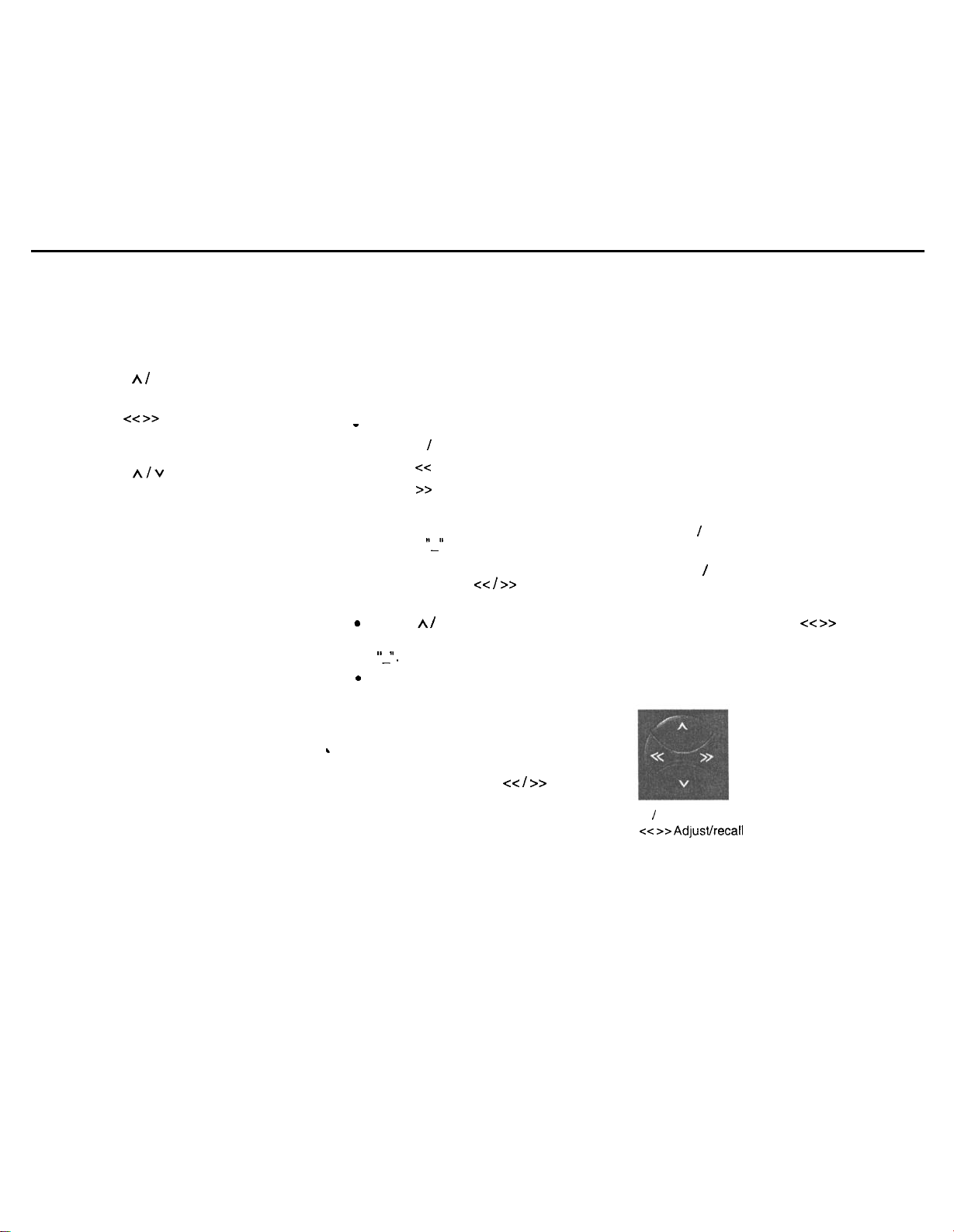
If you wish to alter any of the programming,
l press DSC.
MENU v
/
A will temporarily appear in the
display.
Use the A I v buttons of the rocker switch
to select the function you wish to change.
The display will show you the setting you
have selected. Press the <<
z=>
buttons of
the rocker switch to change the settings and
exit the current mode. Confirm the setting
you have selected by pressing the DSC
button.
A / V
Select function
C-Z >> Adpst/recall
setting
16
Page 17

LOUDNESS
Loudness boosts the bass
frequencies at low volume.
LOUD 1 - Low boost
LOUD 6 - Max. boost
TIMER 2
You can also program the
unit to go to a second
station at a programmed
time.
SCANTIME Use this function to set the
scan time for the radio or
CD changer from 5 to 20
seconds.
SENS LO
To adjust the seek tuning
sensitivity.
“LO” stands for local
reception.
“DX” stands for distant
reception.
STA NAME
Allows you to name up to 30
radio stations based on their
frequency.
CLOCK 12
To switch between 12 and
24-hour clock display.
CLOCKSET To set the clock.
Press << >> to select hours/
minutes. Press v / h to
adjust the flashing value.
TIMER 1 The radio will automatically
switch to a station you have
selected at the time you
program.
ON VOL To set the turn-on volume.
Press <c >> to adjust the
turn-on volume as desired.
TOM ON/OFF Turn-on message.
You can enter a message of
up to 40 characters which
appears in the display when
you switch the unit on.
MUTE
BEEP
To change the mute volume.
To change the volume of the
acknowledgement tone
(beep) between 0 and 9.
(0 = off)
RM ON/OFF
Radio Monitor
If the Radio Monitor function
is active during fast winding
of the tape, the unit will
switch to the radio and play
the station previously
AUX
.
DISPLAY
Select AUX-ON if you wish
to connect a portable CD or
tape player instead of the
CD changer. Contact your
dealer for more information
about the required adapter
cable (7 607 897
093),
which is sold separately.
Display indications on or off
with the car radio turned off.
17
Page 18

Appendix
Overview of the DSC factory
settings
LOUDNESS
SENS
CLOCKTYPE
CLOCKSET
ON VOL
MUTE
BEEP
RM
SCANTIME
AUX
DIS
3
DX
CLOCK 12
20
IO
3
OFF
10 sec.
OFF
ON
Specifications
Amplifier
Power output and total harmonic
distortion:
17 watts per channel minimum continuous
average output into 4 ohms. 4 channels
driven from
than 1% total harmonic distortion.
4 x 40 Watts max. power.
Tuner
Wavebands:
FM
AM
FM frequency response:
Cassette
Frequency response:
CD changer (sold separately)
CDC-A071
CDC-A08
CDC-A05 (with special adapter cable)
Frequency response:
30-I
5000 Hz with no more
:
:
87.5 - 107.9 MHz
530 - 1710
35-16000Hz
35-16000Hz
20 - 20000 Hz
kHz
18
Features and specifications subject to
change without notice.
Page 19

Troubleshooting Guide
The following check will assist in the correction of most problems which you may encounter with your unit. Before going through the
check list below, refer back to the connection and operating procedures.
General
Trouble
No sound.
Radio reception
Trouble
Preset stations are not receivable.
Automatic tuning is not possible.
Travelstore feature does not complete
storing of six stations.
Also make sure that antenna is connected, extended and dry inside.
CD Changer operation
Trouble
CD does not start.
The disk cannot be loaded or is
automatically ejected.
The sound skips due to vibration.
Cause/Solution
l Adjust the volume with the volume knob.
l With a two-speaker system, set the fader control to the center position.
3
Cause/Solution
l The broadcast is too weak.
l The broadcast is too weak
l Not enough broadcast frequencies are receivable.
-
Use manual tuning.
Cause/Solution
l Dusty or defective disc.
l The ambient temperature is more then 50” C (120” F).
l The disc is inserted with the printed side downwards.
l The changer is installed at an angle of more than 20”.
l The changer is not installed on the sturdy part of a car.
l Dusty or defective disc.
19
Page 20

Error Displays
Trouble
“CD ERR”
“NO DISC”
Cause
A disc such as an upside down or dirty
disk, or a CD-ROM (computer) disc.
No magazine or disc in changer
Solution
Insert the disc correctly.
Clean the disc.
Take out the magazine and insert the disc.
If the above mentioned solutions do not help to improve the situation, consult your nearest Blaupunkt dealer or in
the United States call l-800-266-2528.
20
Page 21

Bosch Group
Blaupunkt-Werke
GmbH
Postfach777777
D-31 132 Hildesheim
Germany
Robert Bosch Corporation
Sales Group - Blaupunkt Division
2800 South 25th Avenue, Broadview, Illinois 80153
1-800-950-BLAU
Made in Malaysia
Fabrique en Malasie
Hecho
en Mlasia
Fabricado en Mlaysia
Copyright 1998 by the Robert Bosch Corporation
No portion of this work may be reproduced in any form without
the written consent of the Robert Bosch Corporation.
BPNKD-Nr. 8 822 401 534
Page 22

-
~ --
_
Bosch Group
Arizona CM 148
Colorado CM 168
Florida RD 168
Nevada RDM 168
INSTALLATION INSTRUCTIONS Alaska RDM 168
SAFTEY NOTES & GENERAL RECOMMENDATIONS
To avoid costly mistakes and serious damage, please carefully read all of the instructions
I
.
A
.
.
.
.
.
.
.
.
.
.
before you begin. You’ll be glad you did!
If you’re not confident that you can install the receiver correctly, have it installed by a qualified
Blaupunkt installation technician.
Use this receiver only with negative ground
A quick-acting
During operation of the receiver, the receiver’s sidewall may heat up considerably. Be sure to
keep all wires away from hot parts of the housing.
Do not damage the vehicle’s battery, wiring or fuse box. Before drilling holes, look to see what
is on the other side!
Be sure to observe the safety notes of the vehicle manufacturer, such as those for
systems, on-board computers, immobilisers, and braking systems, etc.
We recommend making and testing all electrical connections before installing the receiver.
Connect the leads (wires) according to instructions below.
Don’t assume that a seemingly-matching wire harness in the vehicle matches the receiver’s wire
harness wire-for-wire. Make sure before you connect anything!
Your Blaupunkt dealer may be able to sell you adapter harnesses for your vehicle, which can
make connections much easier.
Modification of this receiver or its mis-connection and/or mis-installation will void its warranty.
10A
fuse protects this receiver. Do not substitute any other type of fuse.
12-Volt
(1 l-l 6 Volt) direct current (DC).
.
airbags,
alarm
ELECTRICAL CONNECTION INSTRUCTIONS
A. Connect the Wire Harnesses to the Vehicle’s Electrical System (See Fig.
To prevent short circuits or serious damage to the receiver and/or speakers:
1. Disconnect the vehicle battery’s negative terminal before making connections.
Connect the speakers and/or external amplifiers (if you have any) following the guidelines in the
2.
SPEAKER & AMPLIFIER CONNECTION section on the next page.
3. Connect the blue (trigger output) lead to an antenna motor trigger switch input terminal (if you
have one). (Maximum amperage required must not exceed 150
4. Florida RD 168, Nevada RDM 168, and Alaska RDM 168 only: Connect the orange ILLUMINA-
TION lead to the vehicle’s adjustable illumination (dimmer).
Colorado
5.
set that has a mute lead (lead that supplies constant ground when telephone is in use), connect
it to the dark green lead.
8622401550
CM
168,
Nevada RDM 168, and Alaska RDM 168 only: If you have a cellular telephone
mA.)
4)
GB 1
Page 23

Connect the black (power ground) lead to a grounded metal part on the vehicle. We recommend
6.
grounding all audio system black ground leads (receiver, changer,-additional amplifiers, etc.) to
a common grounding point, preferably a non-painted surface under the instrument panel.
Fig. 4
7.
Connect the yellow (constant power) input lead to a source of constant battery power, preferably
directly to the battery. The wire must be
8.
After the other leads are connected, connect the red turn-on “IGNITION” lead using either of the
18-gauge
or thicker.
following alternatives:
A.B.(Recommended) - Connect it to a positive (+) 12 Volt power terminal that is energized only
when the ignition key is set to the “on” position or accessory position. (You can still turn the
unit on for one hour even if the ignition is off.)
This lead can instead be connected to a source of constant power, however, your receiver’s
operation will be completely separate from the ignition.
With either alternative, the receiver’s DSC Setting
“DISP
ON/OFF” allows you to choose whether
or not the receiver and its display are illuminated when the receiver is turned off, but still receiving
power via the red lead.
Cover the ends of any unused leads with electrical tape. This will prevent them from touching the
9.
vehicle or each other and causing a short circuit and damage to the receiver or vehicle.
1 O.Reconnect the vehicle’s battery.
11
.Verify
that no fuses have blown.
.
B.
Test the Connections
1.
To help prevent possible electrical damage from accidental
misconnection
of the receiver, first
attach your vehicle’s antenna. (With Florida RD 168, Nevada RDM 168 and Alaska RDM 168
only: if necessary, attach the antenna “elbow” connector and affixing bracket to the back of the
receiver.)
2.
Be sure to detach the faceplate before you start to connect the receiver.
Plug the harness into the receiver.
3.
4.
Verify that the receiver’s and vehicle’s fuses haven’t blown.
Attach the faceplate and test the receiver.
5.
6.
Once the connections have been successfully made, you can begin the INSTALLATION. (See
below.)
GB2
Page 24

SPEAKER 81 AMPLIFIER CONNECTIONS
The receiver’s Dual-Level Fader allows you to fade between the front and the rear channels using
the receiver’s internally-amplified output via front and/or rear speaker leads AND/OR its 4-channel
preamp output, providing tremendous flexibility in configuring your audio system arrangement:
You can connect a speaker (regular, co-axial or tri-axial speakers or component speaker system,
l
all hereafter referred to simply as “speaker”) to each of the receivers’ four pairs of speaker leads.
With the Blaupunkt preamp output adapter 7 607 893 093 (available separately], you can provide
l
4-channel preamp output to additional external amplifiers and power multiple speakers or
speaker systems through those amplifiers. (Blaupunkt amplifiers and speakers available
separately).
You can use either or both of these two methods.
l
Connecting Speakers to the Outputs from the Receiver’s Internal Amplifier
To prevent short circuits or serious damage to the receiver and/or speakers:
.
Disconnect the vehicle battery’s negative terminal before making connections.
.
Connect the speaker leads only as indicated on the speaker wire block. (See Fig. 6)
.
Only use speakers that have impedance ratings of 4 ohms or higher and have power-handling
capabilities greater than the receiver’s stated power level.
.
The receiver’s internal amplifier is designed to handle a 4-ohm load on each pair of speaker leads.
.
DON’T connect two speakers to a single pair of speaker leads (“in parallel”) unless both speakers
each have at least 8 ohms impedance.
.
DON’T connect the left and right speaker leads to each other or to the same speakers.
.
DON’T connect the front and rear speaker leads to each other or to the same speakers.
.
DON’T connect the negative speaker leads to each other.
.
DON’T connect the positive speaker leads to each other.
.
DON’T connect any active speakers (with built-in amplifiers) to the speaker leads unless their
owner’s manuals specifically state that this is O.K.
.
Cover the ends of any unused leads with electrical tape. This will prevent them from touching the
vehicle or each other and causing a short-circuit and damage to the receiver or vehicle.
.
Make the other electrical connections. (See previous page.)
GB3
Page 25

Connecting Additional Amplifiers or an Equalizer to the Receiver’s Preamp Output
Obtain the Blaupunkt RCA 4-channel preamp output adapter 7 607 893 093 from your dealer.
It includes a blue/white trigger lead for switching the amplifier on and off. Connect the adapter into
the top left section of the connector block on the back of the receiver. (See Fig. 7) Follow the
amplifier’s or equalizer’s instructions regarding connection. (Blaupunkt amplifiers available separately).
.
Fig. 7
fi4’,$”
CD CHANGER OR AUX-IN CONNECTION
(Arizona, CM 148, Colorado CM 168, Nevada RDM 168, & Alaska RDM 168 Receivers)
CD Changer Connection
These receivers can control a Blaupunkt CDC-A08 or CDC-A071 CD Changer (or with the adapter
harness 7 607 889 093, they can control a Blaupunkt CDC-A05 CD Changer)
(Al/available separately.) The changer cable plugs into the right top connector block on the back of
the receiver. (See Fig. 6) See the changer instructions for details.
Fig. 6
Aux Input
If a changer is not connected, you can connect portable audio equipment to your receiver by
purchasing Blaupunkt accessory harness 7 607 897 093. It connects to the right top block on the rear
of the receiver. It includes a 2-meter aux-in cable with a 3.5 mm male plug for direct insert into your
portable equipment.
WIRELESS REMOTE CONTROL
(Colorado CM 168, Nevada RDM 168, & Alaska RDM 168 only)
This receiver’s most-frequently used features can be conveniently controlled from the steering
wheel with Blaupunkt’s unique Thummer III Steering-Wheel Remote Control.
(Availableseparately.)
The Thummer III includes a receiving “eye” that can be placed virtually anywhere on the dash, which
connects into the center top block on the back of the receiver.
GB4
Page 26

INSTALLATION
Recommendations
l
Carefully choose the mounting location so that the receiver won’t interfere with normal driving.
l
Avoid mounting locations where the receiver would be subject to high temperatures, such as from
INSTUCTIONS
.
direct sunlight or hot air from the heater, or where it would subject to dust, dirt or excessive
vibration.
l The illustration below shows a typical installation, however, you may need to adjust the
installation, depending on the receiver. If you have questions or need additional installation
hardware, consult your Blaupunkt dealer.
l
Make sure the receiver
is
firmly
anchored (preferably at both front and back) and does not vibrate.
Installing the Receiver in Most Dashboards
This car receiver and its mounting bracket are designed for installation in vehicles with a standard
DIN installation compartment measuring 182 x 53 mm, a 165 mm installation depth and an
instrument panel thickness of approximately 1 to 20 mm
in.
the area of the tab fasteners.
(See Fig. 1)
1.
Place the mounting bracket in the compartment and bend over all of the tabs possible.
(See Fig. 2)
2.
Your vehicle may also allow you to provide extra stability at the back of the receiver. Look at the
wall behind the radio cavity to see if there is a small hole the size of the enclosed plastic plug,
If so, screw it onto the treaded bold at the back of the receiver before pushing it into the mounting
bracket.
3.
With the detachable face off, place the receiver into the mounting bracket and push it in until the
side springs snap into position on the left and right. (You will hear an audible click.)
4.
To remove the receiver, see the maintenance section on the next page.
Fig. 1
Fig. 2
GB5
Page 27

Installing the Receiver in a Japanese Car
This receiver is designed for easy installation in most popular Japanese cars that have “ISO”
(side-
bracket) mounting system. If you have questions, ask your Blaupunkt dealer.
1.
Remove the vehicle’s “bezel” trim piece and the remove the existing radio.
2.
Unscrew the bolts on each side of the receiver to remove the trim ring. Save the trim ring in case
you ever want to install the receiver in another vehicle.
3.
Use the vehicle’s own mounting hardware to attach the unit.
4.
With the detachable face removed, reinstall the vehicle’s bezel.
5.
Only after the bezel in reinstalled, attach the face.
max.
M5x8
NISSAN
max.
max.
M5x8
&M5x8
TOYOTA
max.
M5x8
MAINTENANCE
Removing the Receiver
Insert the “release handles” into the holes in the panel on the left and right of the receiver and push
them in until you hear a distinct snap, which indicates the side springs are unlocked. Pull the unit
out using both handles. (See Fig. 3) Note: Handles that have snapped into place can only be
removed after you have pulled the receiver out of the complement. Remember where you store the
“release handles”.
Fig. 3
Fuse Replacement
When replacing the fuse, be sure to use one with the correct amperage, which will be stated on the
fuse case. Never use a fuse that has a stated amperage exceeding the one supplied for this
receiver as this could cause malfunction and serious damage to the receiver.
GB6
Page 28

Cleaning the Connectors
The receiver may not operate properly if the connectors between the receiver and the detachable
face are contaminated with dirt. To clean the connectors, use a cotton swab and isopropyl alcohol
(90% or higher). Be sure to clean them with a vertical motion. Never clean them horizontally,
because this could damage the contact points.
Affixing the Detachable Face for Retail Display
The detachable face can be affixed to the receiver’s chassis, which is desirable for a retail display.
To affix the face, obtain the small self-tapping screw from the hardware pack and drive it into the
upper hole at the front left side of the chassis using a Phillips screwdriver. The bolt will self-thread
the hole. (See Fig. 8)
Fig. 8
Faceplate affixing screw goes here
.
TROUBLESHOOTING - Refer to the receiver’s Owner’s Manual. If you have questions, please
consult your Blaupunkt dealer or in the United States call l-800-266-2528.
Installer - These Installation Instructions are the property of the consumer!
Make sure they are left in the vehicle!
8622401550
GB7
 Loading...