


KOMFORT EC DW
BLAUBERG Ventilatoren KOMFORT EC DW, KOMFORT EC DW600-2, KOMFORT EC DW2000-2, KOMFORT EC DW3800-2, KOMFORT EC DW1000-4 Operation Manual
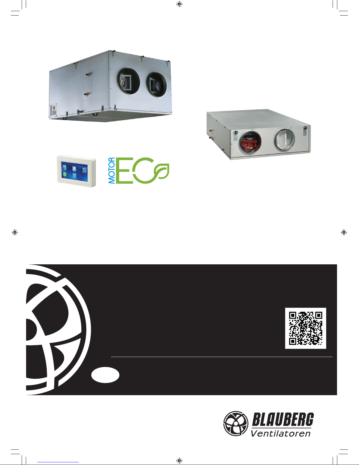
KOMFORT EC DW
AIR HANDLING UNITS
WITH HEAT RECOVERY
OPERATION MANUAL
EN
KOMFORT EC DW v1(6)_EN.indd 1 10.08.2015 10:10:59
2
www.blaubergventilatoren.de
KOMFORT EC DW
CONTENTS
3 Introduction
3 General
3 Safety rules
3 Transportation and storage rules
3 Manufacturer's warranty
4 Design
5 Operating logic
5 Delivery set
6 Technical data
9 Mounting
11 Condensate drainage
12 Connection to power mains
15 Outdoor temperature sensor mounting and connection
15 Duct humidity sensor mounting and connection
16 Control panel mounting
18 Unit control
27 Error code description
27 Factory settings
28 Technical maintenance
29 Troubleshooting and fault handling
30 Acceptance certicate
30 Connection certicate
30 Warranty card
KOMFORT EC DW v1(6)_EN.indd 2 10.08.2015 10:10:59

www.blaubergventilatoren.de
3
KOMFORT EC DW
BLAUBERG Ventilatoren GmbH Company is happy to oer your
attention a suspended heat recovery air handling unit KOMFORT EC DW.
INTRODUCTION
The present operation manual contains a technical description, technical
data sheets, operation and mounting guidelines, safety precautions and
warnings for safe and correct operation of the unit.
Read carefully and understand the operation manual, especially the
safety requirements, before the unit mounting and start up.
Keep the operation manual available as long as you use the unit.
GENERAL
The heat recovery air handling unit KOMFORT EC DW is designed for
ecient and energy saving ventilation of domestic and public premises.
The unit is not a ready to use product but a component part of central air
conditioning and ventilation network.
The unit is designed for suspended mounting.
The unit is rated for indoor application at ambient temperature from +1
°C up to +40 °C and relative humidity not exceeding 80%.
Hazardous parts access and water ingress protection rating:
unit motors - IP 44;
assembled unit connected to air ducts - IP 22.
The unit design is regularly improved, so some models can slightly dier
from those ones described in this service instruction.
SAFETY RULES
All operations related to the unit electrical connections, servicing and
repair works are allowed only after the appliance is disconnected from power
supply.
The appliance is rated as a Class I electrical appliance.
All mounting and servicing operations are allowed by duly qualied
personnel.
Please, follow the safety regulations and working instructions (DIN EN 50
110, IEC 364).
Make sure the impeller and the casing are not damaged before
connecting the appliance to power supply. The casing internals must be free
of any foreign objects which can damage the impeller blades or the motor.
The appliance maintenance and repair is allowed only after power cut-o
and full stop of the rotating parts.
Misuse of the appliance or any unauthorized modication are not allowed.
The appliance is designed for connection to power supply in compliance
with the «Technical data» section.
The appliance is rated for permanent operation.
Take steps to prevent ingress of smoke, carbon monoxide and other
combustion products into the room through open chimney ues or other
re-protection devices. Sucient air supply must be provided for proper
combustion and exhaust of gases through the chimney of fuel burning
equipment to prevent back drafting. The maximum permitted pressure
dierence per living units is 4 Pa.
The transported air must not contain any dust or other solid impurities,
sticky substances or brous materials.
The appliance is not rated for operation in a ammable or explosive
medium.
Full the operation manual requirements to ensure a trouble-free and
long service life of the appliance.
TRANSPORTATION AND STORAGE RULES
Transportation of the appliance is allowed by any vehicle provided the
appliance is transported in the original package and is protected against
weather and mechanical damages.
Use hoist machinery for handling and transportation to prevent
possible mechanical damages of the appliance. Full the requirements for
transportation of the specied cargo type during cargo-handling operations.
Store the appliance in a dry and cool place in the original packing.
The storage environment must not be subjected to any aggressive and/
or chemical evaporations, admixtures, foreign objects that may provoke
corrosion and damage connection tightness.
Store the appliance in an environment with minimized risk of mechanical
damages, temperature and humidity uctuations.
Do not expose the appliance to the temperatures below +5 °C and above
+40 °C .
Connection of the appliance to power supply is allowed after the
appliance has been kept indoor for minimum two hours.
MANUFACTURER’S WARRANTY
The appliance complies with the requirements according to the EU norms
and directives, to the relevant EU-Low Voltage Equipment Directives, EUDirectives on Electromagnetic Compatibility.
We hereby declare that the unit complies with the essential protection
requirements of Electromagnetic Council Directive 2004/108/EC, 89/336/EEC
and Low Voltage Directive 2006/95/EC, 73/23/EEC and CE-marking Directive
93/68/EEC on the approximation of the laws of the Member States relating
to electromagnetic compatibility, which relate to electrical appliances used
in set voltage classes.
The manufacturer hereby warrants normal operation of the unit over
the period of two years from the retail sale date provided observance of the
installation and operation regulations.
In case of a failure due to a manufacturing fault during the warranty
period the consumer has the right to exchange it.
The replacement is oered by the Seller.
If case of no conrmation of the sale date, the warranty period shall be
calculated from the manufacturing date.
The MANUFACTURER is not responsible for any damage resulting from
any misuse of or gross mechanical interference with the unit.
The MANUFACTURER is not responsible for the damages resulted due to
the use of third party equipment or to third party equipment.
WARNING
Do not dispose in domestic waste.
The unit contains in part materials that can be
recycled and in part substances that should not end up
as domestic waste.
Dispose of the unit once it has reached the end of its
working life according to the regulations valid in your
country.
WARNING
The unit is not allowed for use by children and persons with reduced
physical, mental or sensory capacities, without proper practical experience
or expertise, unless they are controlled or instructed on the product operation by the person(s) responsible for their safety.
Supervise the children and do not let them play with the product.
!
KOMFORT EC DW v1(6)_EN.indd 3 10.08.2015 10:11:00

4
www.blaubergventilatoren.de
KOMFORT EC DW
Fig. 1. Unit design and operating logic
DESIGN
The casing is made of double-skinned aluzinc panels, internally lled
with mineral wool layer 20 or 25 mm for heat- and sound-insulation. The
casing has mounting brackets with anti-vibration rubber mounts for easy
installation. The spigots are located at the sides of the unit and are equipped
with rubber seals for airtight connection to the air ducts. The service panel
ensures easy access to the unit internals for service works including cleaning,
lter replacement, etc.
The unit is equipped with high-ecient external rotor EC motors and
centrifugal impellers with backward curved blades.
The KOMFORT EC DW600/1000 models are equipped with highecient counter-ow aluminium heat exchangers with a large
surface area. The KOMFORT EC DW2000/3800 models are equipped with
high-ecient cross-ow plate aluminium heat exchangers with a large
surface area. The air ows are fully separated within the heat exchanger.
Odours and contaminants contained in the extract air are not transferred to
the supply air ow. Heat recovery is based on the utilization of the thermal
energy of the extract air for heating up supply air. The process of heat transfer
proceeds in the heat exchanger where extract air transfers most of its heat
to the intake air ow. This reduces thermal energy losses in cold seasons. In
summer heat recovery acts reverse. The cooled extract air transfers part of
cold to the warm intake air. This contributes to better performance of the air
conditioner in ventilated premises.
The electronic frost protection system based on bypass and heater is used
to prevent the heat exchanger freezing in cold seasons. The bypass damper is
opened and the heater is turned on automatically according to temperature
sensor readings.
Cold intake air passes by the heat exchanger and is warmed up to set
temperature in the heater. Synchronously extract air that passes by the heat
exchanger is used for its defrosting.
After the freezing danger is over the bypass damper is
closed, the heater is turned o, the intake air passes through the heat
exchanger again and is warmed. The heat exchanger reverts to the regular
operation mode.
The drain pan under the heat exchanger block is used for condensate
collection and drainage.
The units are equipped with a water (glycol) heater for operation at low
outside temperatures.
The integrated water heater is activated to warm up supply air ow if set
indoor air temperature may not be reached by means of heat recovery only.
Smooth water heater control ensures automatic control of supply air
temperature.
The air temperature sensor downstream of the heater and the return
water temperature sensor are used for freezing protection of the water
heater.
The KOMFORT EC DW600/1000 models include built-in G4 (optionally
F7) pocket supply lters and G4 cassette extract lters. The KOMFORT EC
DW2000/3000 models include built-in G4 supply and extract cassette lters.
The unit incorporates an integrated control system with a wall-mounted
control panel with a sensor display. The standard delivery set includes a 10 m
cable for connection of the unit to the control panel.
KOMFORT EC DW600-2 ... KOMFORT EC DW1000-4
KOMFORT EC DW2000-2 ... KOMFORT EC DW3800-2
Supply lter
Control unit
Water heater
Heat exchanger
Extract fan
Supply fan
Extract lter
Heat exchanger
EXTRACT AIR
SUPPLY AIR
EXHAUST AIR
INTAKE AIR
INTAKE AIR
EXTRACT AIR
EXHAUST AIR
SUPPLY AIR
Supply fan
Water heater
Condensate drain pipe
Extract lter
Bypass
Control unit
Extract fan
Drain pan
Condensate drain pipe
Bypass air damper actuator
Heat exchanger
Supply lter
KOMFORT EC DW v1(6)_EN.indd 4 10.08.2015 10:11:01
www.blaubergventilatoren.de
5
KOMFORT EC DW
OPERATING LOGIC
Cold fresh air from outside ows through the heat exchanger and is
moved to the room with the supply fan.
Warm extract air is extracted from the room with the exhaust fan and is
moved through the heat exchanger, where it transfers its heat energy to the
intake air. After that it is exhausted outside.
Heat energy of warm and humid extract air is transferred to the cold fresh
air. The air ows are fully separated while owing through the heat exchanger.
Heat recovery minimizes heat losses caused by traditional window
ventilation and saves energy.
In summer the heat exchanger performs reverse and transfers cold
from the cooled extract air to the warm fresh air. This contributes to better
performance of the air conditioner in ventilated premises.
DELIVERY SET
Air handling unit - 1 item;
Operation manual - 1 item;
Wall-mounted control panel - 1 item;
Packing box - 1 item.
ATTENTION
Make sure the unit has no visible transport damages
while accepting the goods. Check the ordered and the
delivered goods for compliance.
!
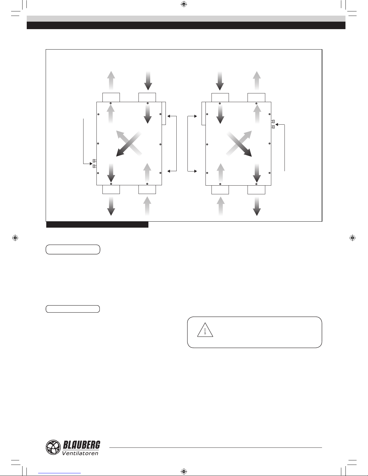
For mounting facilitation the KOMFORT EC DW600-2/1000-4 unit is available both in left- and right-handed modications.
Fig. 2. KOMFORT EC DW600-2/DW1000-4 modications
SUPPLY AIR
EXTRACT AIR
EXHAUST AIR
EXHAUST AIR
INTAKE AIR
INTAKE AIR
SUPPLY AIR
EXTRACT AIR
RIGHT-HANDED MODIFICATION
(TOP VIEW)
LEFT-HANDED MODIFICATION
(TOP VIEW)
SERVICE SIDE
SERVICE SIDE
WATER HEATER CONNECTION
WATER HEATER CONNECTION
KOMFORT EC DW v1(6)_EN.indd 5 10.08.2015 10:11:01

6
www.blaubergventilatoren.de
KOMFORT EC DW
TECHNICAL DATA
Table 1. Technical data of the unit
Table 2. Accessories
Table 3. Overall dimensions
Fig. 3. Fig. 4.
Model Replaceable G4 pocket lter Replaceable F7 pocket lter Replaceable G4 cassette lter Replaceable G4 cassette lter
KOMFORT EC DW600-2 FPT-EC DW600 G4 FPT-EC DW600 F7 - FP-EC DW600 G4
KOMFORT EC DW1000-4 FPT-EC DW1000 G4 FPT-EC DW1000 F7 - FP-EC DW1000 G4
KOMFORT EC DW2000-2 - - FP-EC DW2000 G4
KOMFORT EC DW3800-2 - - FP-EC DW3800 G4
Parameters
KOMFORT EC
DW600-2
KOMFORT EC
DW1000-4
KOMFORT EC
DW2000-2
KOMFORT EC
DW3800-2
Unit voltage [V /50-60 Hz] 1~ 230 3~ 400
Number of water heater rows 2 4 2 2
Power [kW] 0,27 0,4 0,84 1,99
Current [A] 1,6 2,26 5 3,4
Max. air capacity [m3/h] 600 1000 1950 3800
RPM 3060 2780 2920 2580
Sound pressure level at 3 m distance [dB(A)] 53 52 58 59
Transported air temperature [°C] -25 up to +60 -25 up to +40 -25 up to +50
Casing material aluzinc
Insulation 20 mm mineral wool 25 mm mineral wool
Extract lter cassette G4
Supply lter pocket G4 (F7)* cassette G4
Connected air duct diameter [mm] 200 250 315 400
Weight [kg] 77 98 194 295
Heat recovery eciency [%] up to 90 up to 75
Heat exchanger type counter-ow cross-ow
Heat exchanger material aluminum
*option
Model
Dimensions [mm]
Figure
no.
Water heater pipe size,
inch
D B B1 B2 B3 B4 H H1 L L1
KOMFORT EC DW600-2 199 827 711 - 294 345 283 - 1238 1286
3
G 1/2”
KOMFORT EC DW1000-4 249 1350 1215 607,5 430 655 317 - 1395 1395 G 3/4”
KOMFORT EC DW2000-2 314 950 - 405 225 500 761 367 1400 1453
4
G 1 1/4”
KOMFORT EC DW3800-2 399 1265 - 563 347 570 881 427 1835 1888 G 3/4”
KOMFORT EC DW v1(6)_EN.indd 6 10.08.2015 10:11:02
www.blaubergventilatoren.de
7
KOMFORT EC DW
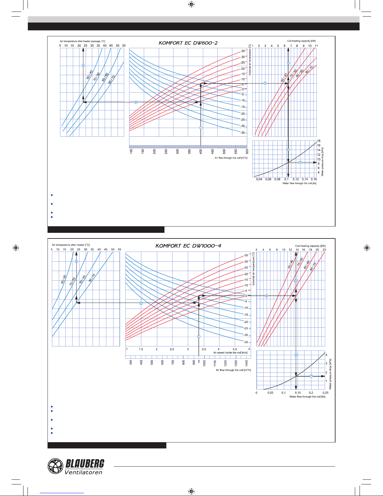
How to use water heater diagrams
Sample parameters: Air ow = 400 m3/h. Outside air temperature =-20°C. Water temperature (in/out) = 70/50 °C.
Supply air temperature: prolong the line of air ow (e.g. 400 m3/h) up to the point where it crosses the outside air temperature (blue curve, e.g. -20°C); then draw a horizontal line from this point to the left until it crosses
the water in/out temperature curve (e.g. 70/50 °C). From this point draw a vertical line to the supply air temperature axis on top of the graphic (+23°C).
Heating coil capacity: Prolong the line up to the point where it crosses the outside air temperature (e.g. -20°C, red curve) and draw a horizontal line from this point to the right until it crosses the water in/out temperature
curve (e.g., 70/50 °C). From here draw a vertical line up to the scale representing the heating coil capacity (6.6 kW).
Water ow: Prolong the line down to the water ow axis at the bottom of the graphic (0.105 l/s).
Water pressure drop: Draw the line from the point where the line crosses the black curve to the pressure drop axis (8.5 kPa).
Fig. 5. KOMFORT EC DW600-2 hot water coil calculation diagram
Fig. 6. KOMFORT EC DW1000-4 hot water coil calculation diagram
How to use water heater diagrams
Sample parameters: Air ow = 950 m3/h. Outside air temperature =-15°C. Water temperature (in/out) = 90/70 °C.
Air Speed inside coil: Starting from 950 m3/h on the air ow scale draw a vertical line . This line crosses the air speed axis and shows a value of about 3.35 m/s.
Supply air temperature: prolong the line up to the point where it crosses the outside air temperature (blue curve, e.g. -15°C); then draw a horizontal line from this point to the left until it crosses the water in/out
temperature curve (e.g. 90/70 °C). From this point draw a vertical line to the supply air temperature axis on top of the graphic (+23°C).
Heating coil capacity: Prolong the line up to the point where it crosses the outside air temperature (e.g. -15°C, red curve) and draw a horizontal line from this point to the right until it crosses the water in/out temperature
curve (e.g., 90/70 °C). From here draw a vertical line up to the scale representing the heating coil capacity (13.5 kW).
Water ow: Prolong the line down to the water ow axis at the bottom of the graphic (0.14 l/s).
Water pressure drop: Draw the line from the point where the line crosses the black curve to the pressure drop axis (1.5 kPa).
KOMFORT EC DW v1(6)_EN.indd 7 10.08.2015 10:11:02
8
www.blaubergventilatoren.de
KOMFORT EC DW
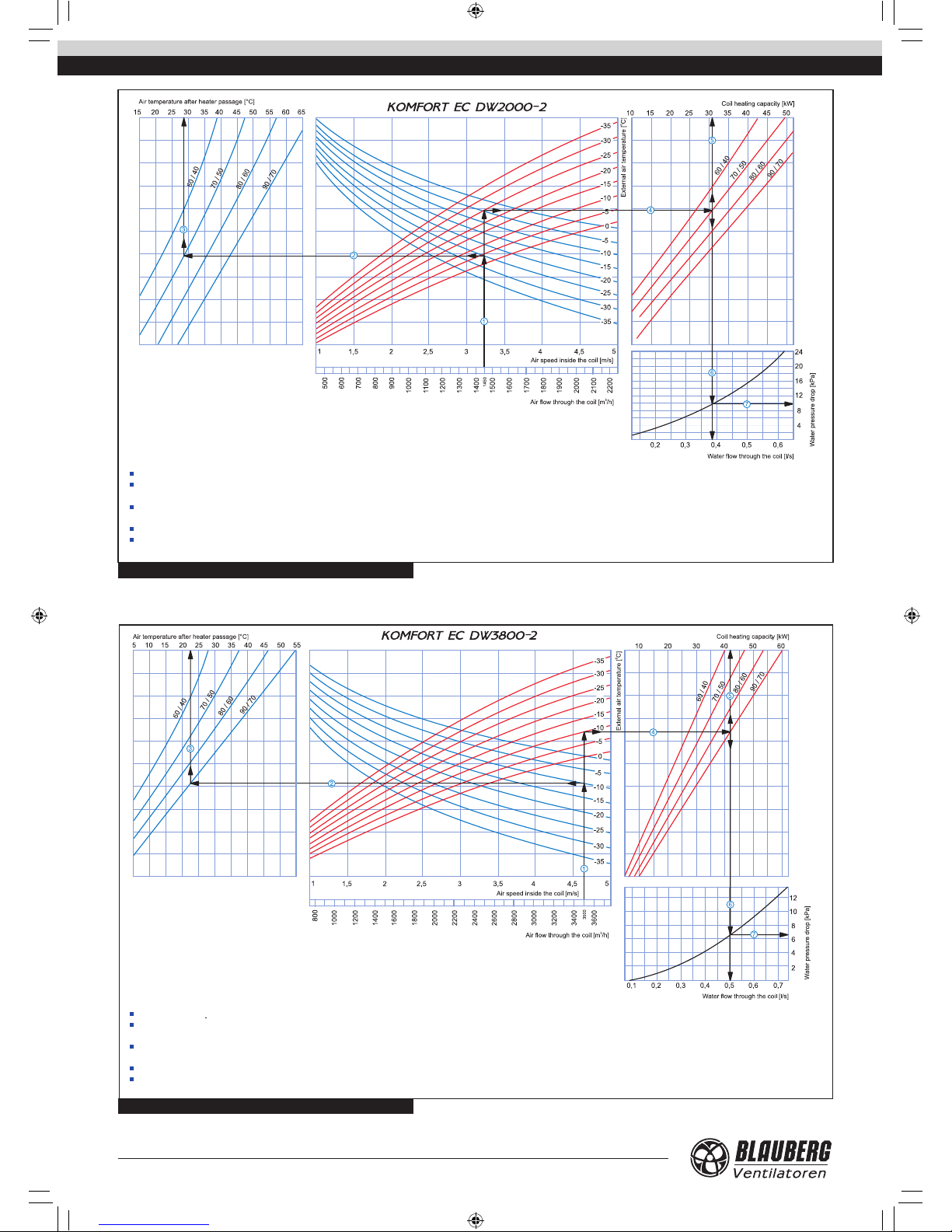
How to use water heater diagrams
Sample parameters: Air ow = 1450 m3/h. Outside air temperature =-25°C. Water temperature (in/out) = 70/50 °C.
Air Speed inside coil: Starting from 1450 m3/h on the air ow scale draw a vertical line . This line crosses the air speed axis and shows a value of about 3,2 m/s.
Supply air temperature: prolong the line up to the point where it crosses the outside air temperature (blue curve, e.g. -25°C); then draw a horizontal line from this point to the left until it crosses the water in/out
temperature curve (e.g. 70/50 °C). From this point draw a vertical line to the supply air temperature axis on top of the graphic (+28°C).
Heating coil capacity: Prolong the line up to the point where it crosses the outside air temperature (e.g. -25°C, red curve) and draw a horizontal line from this point to the right until it crosses the water in/out temperature
curve (e.g., 70/50 °C). From here draw a vertical line up to the scale representing the heating coil capacity (31.0 kW).
Water ow: Prolong the line down to the water ow axis at the bottom of the graphic (0.38 l/s).
Water pressure drop: Draw the line from the point where the line crosses the black curve to the pressure drop axis (9.8 kPa).
Fig. 7. KOMFORT EC DW2000-2 hot water coil calculation diagram
Fig. 8. KOMFORT EC DW3800-2 hot water coil calculation diagram
How to use water heater diagrams
Sample parameters: Air ow = 3500 m3/h. Outside air temperature =-10°C. Water temperature (in/out) = 90/70 °C.
Air Speed inside coil: Starting from 3500 m3/h on the air ow scale draw a vertical line . This line crosses the air speed axis and shows a value of about 4.65 m/s.
Supply air temperature: prolong the line up to the point where it crosses the outside air temperature (blue curve, e.g. -10°C); then draw a horizontal line from this point to the left until it crosses the water in/out
temperature curve (e.g. 90/70 °C). From this point draw a vertical line to the supply air temperature axis on top of the graphic (+22,5°C).
Heating coil capacity: Prolong the line up to the point where it crosses the outside air temperature (e.g. -10°C, red curve) and draw a horizontal line from this point to the right until it crosses the water in/out temperature
curve (e.g., 90/70 °C). From here draw a vertical line up to the scale representing the heating coil capacity (42.0 kW).
Water ow: Prolong the line down to the water ow axis at the bottom of the graphic (0.5 l/s).
Water pressure drop: Draw the line from the point where the line crosses the black curve to the pressure drop axis (6.5 kPa).
KOMFORT EC DW v1(6)_EN.indd 8 10.08.2015 10:11:03
www.blaubergventilatoren.de
9
KOMFORT EC DW
MOUNTING
!
Safety precautions:
The unit must be mounted to a rigid and stable structure.
The unit must be suspended using anchor bolts. Before starting mounting check that the mounting structure has sucient
loading capacity for the unit weight.
The unit mounting is allowed only after power cut-o and full stop of the rotating parts.
Restrictions:
• Do not operate the unit beyond the determined temperatures, in aggressive and in explosive medias.
• Do not connect the clothes dryer or other similar equipment to the ventilation system.
• Do not use the unit for air/dust mixture handling.
WARNING
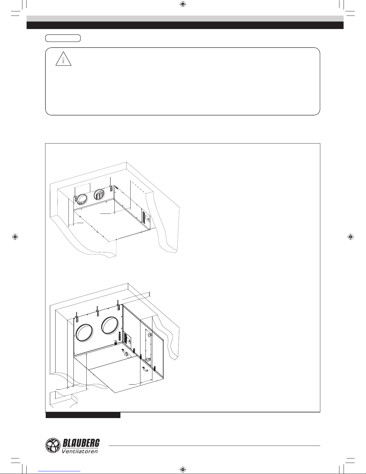
The unit mounting position must provide condensate drainage and access
to the terminal box for electric connection and access to the service panel for
maintenance and lter replacement (Fig. 9).
Fig. 9. Minimum service access to the unit
A - minimum required access distance for water heater installation.
The distance is selected depending on the installation conditions at the
discretion of the installer.
B = min 850 mm for KOMFORT EC DW600-2
B = min 800 mm for KOMFORT EC DW1000-4
A - minimum required access distance for condensate drainage.
The distance is selected depending on the installation conditions at the
discretion of the installer.
B - minimum required access distance for water heater installation and
condensate drainage. The distance is selected depending on the installation
conditions at the discretion of the installer.
C - minimum required distance from the service panel to the floor.
C = min 1000 mm for KOMFORT EC DW1000-2.
C = min 1300 mm for KOMFORT EC DW3800-2.
KOMFORT EC DW600-2 / KOMFORT EC DW 1000-4
KOMFORT EC DW2000-2 / KOMFORT EC DW 3800-2
min 20 mm
min B
A
min 20 mm
B
A
min C
KOMFORT EC DW v1(6)_EN.indd 9 10.08.2015 10:11:04
10
www.blaubergventilatoren.de
KOMFORT EC DW
Fig. 10. Mounting
Washer
Nut
Vibration absorbing
rubber
Nut and lock
nut
The unit is suspended using threaded rods and threaded dowels.
The unit must be mounted to an even surface to avoid the unit casing
distortion and operation disturbances. The installation place must have
connection to the drain system. While planning the ductwork layout
avoid too long air duct sections, numerous bends and reducers because
it may reduce air ow. The mounted air ducts must not be deformed.
Provide airtight connection of the air ducts to the unit spigots and ttings.
Install straight air ducts on both sides of the unit to minimize aerodynamic
resistance caused by air ow turbulence, the minimum air duct section
length is equal to 1 time air duct diameter on the inlet side and 3 time air
duct diameters on the outlet side.
In case of insucient length or no air duc ts cover the unit spigots with a
protecting g rille or any other protecting de vice with maximum mesh width
12.5 mm to prevent ingress of fore ign objects inside the uni t and to prevent
contact with fans of the unit.
Prior to star ting mounting make sure the mountin g surface has sucient
load capacit y matching the unit weight. O therwise reinfo rce the installation
place with beams. Use threaded rods of sucient length to avoid possible
resonance with a mounting surface. If the connection point of the spiral
seam air duct to the unit is supposed to be a source of noise generation,
replace a spiral seam air duct with a exible air duct. The exible antivibration connectors (specially ordered accessories) may also be useful.
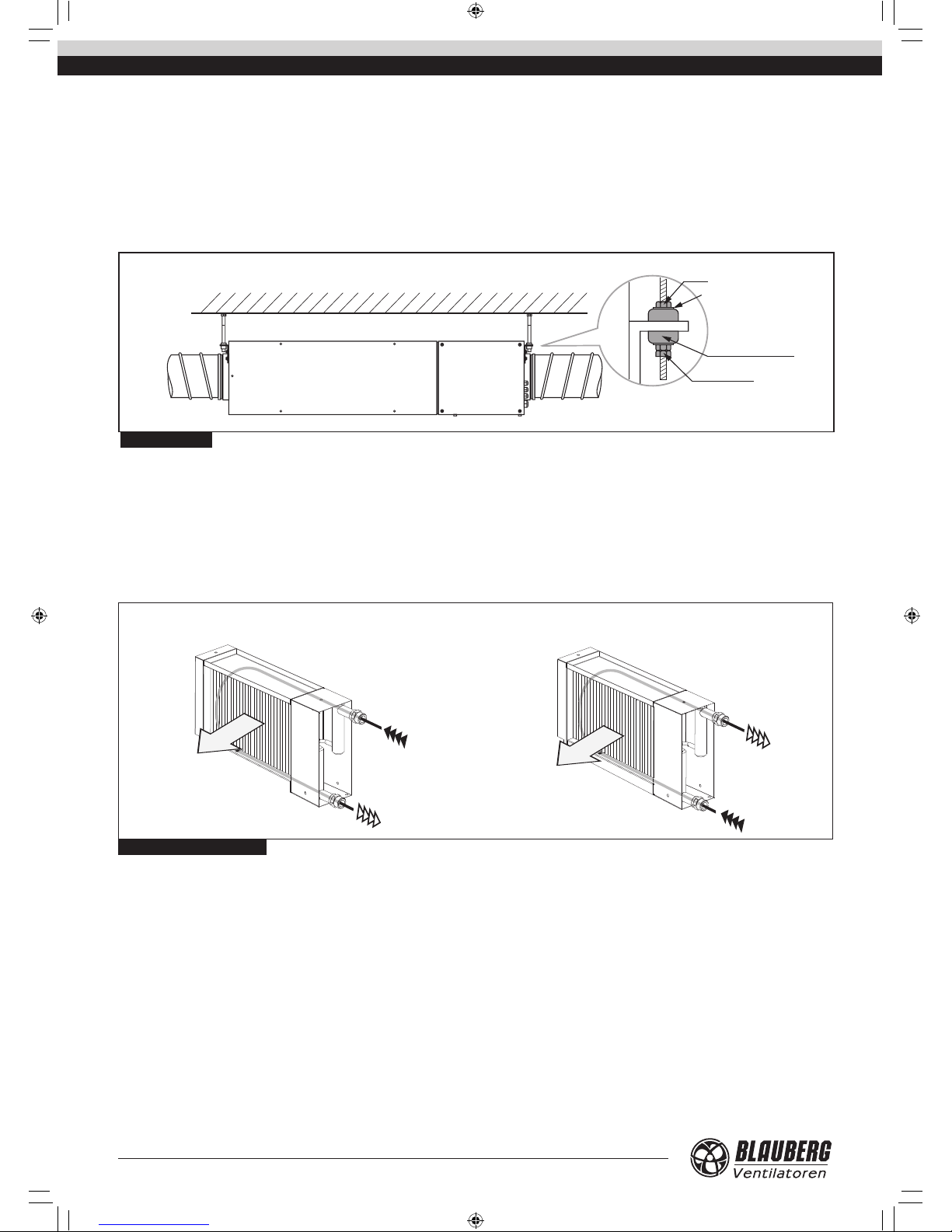
Fig. 11. Water heater connection
In order to achieve maximum power the water heater should be counterow connected (Fig. 11). All calculation diagrams (ref. Fig. 5-8) are valid for
the counter-ow connection of the water heater.
In case of the direct-ow basis connection the water heater has lower
power but higher frost-resistant properties.
Counter-ow connectionDirect-ow connection
water inlet
water return
water inlet
water return
ATTENTION!
The unit operates either in Winter or Summer mode. If the outside air temperature is below +10 °C the Winter mode is activated. If the outside temperature
accedes +10 °C the unit operates in Summer mode.
In Summer mode the unit operates regardless of the return heat medium temperature in the mixing unit.
In Winter mode the unit has following temperature limits:
The unit may not be started when the return heat medium temperature is below +40 °C. If the return heat medium temperature is +40 °C and higher
the unit will be turned on with a 90 seconds delay.
The unit turns o when the return heat medium temperature falls below +20 °C.
KOMFORT EC DW v1(6)_EN.indd 10 10.08.2015 10:11:04
 Loading...