

Page 1
Installation and Operation Manual
Cintel
Scanner
April 2018
Page 2

English
Welcome
Thanks for purchasing your new Cintel scanner!
Your new scanner runs film in real time so you can transfer film much faster than a traditional
scanner that runs non real time using a constant start-stop motion. However it’s important to
understand that your scanner is not a telecine and it does not transfer film to video, as it
transfers film direct to DaVinci Resolve where you have the power to edit the film rolls back
together and the scans can be color graded, reframed, noise reduced and the audio extracted.
Using DaVinci Resolve to operate the scanner means you have much more creative control
than a simple telecine because DaVinci Resolve has many more features than is possible to do
in hardware. Plus because Cintel takes advantage of the power of the DaVinci Resolve system
and the GPU’s in the host computer, this scanner itself does not need to be cluttered with
bulky expensive electronics assemblies.
This means Cintel is smaller, lighter and has more value engineered into the parts of the
scanner that result in better quality film scans, such as precision mechanical film handling
components, optics, high intensity diffuse light source and the built in camera.
The scanning workflow is simple as all you need to do is scan your film to intermediate RAW
files and then once you have joined the film rolls back together in the timeline, added noise
reduction, color grading and reframing, you can use DaVinci Resolve’s deliver page to render
out files to any format you like.
We’ve also designed attachments to improve your workflow. The optional Audio and KeyKode
Reader attachment can scan optical or magnetic audio faster than real time, as well as importing
KeyKode information directly into your DaVinci Resolve clips.
You might need to render to DPX frames to use third party film restoration software or you
might want to render to DNX or ProRes files for use in editing software. You can even render
out digital cinema package files if you want to digitally project the film!
Your scanner is designed to work in conjunction with DaVinci Resolve so you get incredible
power and amazing quality, so please read through this manual carefully so you can learn all
about how to use your new scanner.
Of course with all the power of DaVinci Resolve available with your scanner, it’s also important
to check out the available DaVinci Resolve manual and tutorials. There are some great
customer tutorial videos on using DaVinci Resolve as well as high quality training available
from third party vendors to help you get the most out of your DaVinci Resolve system.
Grant Petty
CEO Blackmagic Design
Page 3

Contents
Cintel Scanner
Unpacking and Mounting 4
Desk Mounting 5
Wall Mounting 6
Warning for Safely Installingyour Scanner 7
Getting Started 7
Installing the Software 7
Plugging in Power 8
Connecting to a Computer 8
Launching DaVinci Resolve 8
Lacing Film 9
Using Your Scanner 14
Wind Types 14
Switching to 16mm 15
Playback Controls 17
Standby Mode 18
Capturing from Cintel
usingDaVinciResolve 18
The Cintel Scanner Interface 19
Calibration 19
Film Type 20
Light Source 21
Image Stabilization 22
Film Protection 23
Editing Capture Info Metadata 24
Film Scanning Workflows 26
Before You Begin 26
Load and Align the Film 26
Focus the Scanner 26
Reset the Timecode 27
Choose a Location to Save
the Scanned Frames 28
Check the Codec 28
Adjusting the Color of the Scanner 29
Scanning One or More Sections of Film 30
Extracting Audio 30
Audio Extraction Settings 31
Color Space and Sizing 34
Optional Audio andKeyKode Reader 36
Attaching the Audio and
KeyKode Reader 36
Reading Audio 39
Setting the Reader for Audio Scanning 40
Reading KeyKode 44
Setting the Reader for
KeyKode Scanning 45
Transcoding to DPX including
KeyKode Metadata 46
Updating the Audio and
KeyKode Reader’s Internal Software 46
Servicing 48
Working with Clips in DaVinci Resolve 51
Importing your Clips 51
Editing your Clips 52
Trimming Clips 53
Mapping Keyboard Shortcuts 54
Adding Transitions 55
Adding Titles 56
Color Correcting your Clips 57
Using Scopes 58
Secondary Color Correction 59
Qualifying a Color 60
Adding a Power Window 60
Tracking a Window 62
Using Plugins 62
Mixing Your Audio 63
The Fairlight Page 64
The Audio Timeline 64
What is a Bus? 65
The Mixer 65
Using the Equalizer to
Enhance your Audio 66
Mastering your Edit 68
Reducing Grain using Noise Reduction 69
Noise Reduction Settings 69
Specifications 74
Regulatory Notices
andSafetyInformation 76
Help 78
Warranty 81
3Contents
Page 4
1
2
13
12
3
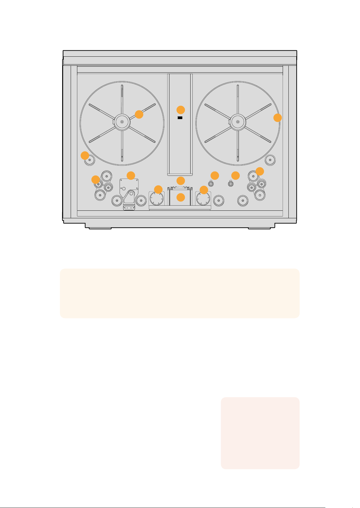
1. Core clamp 2. Roller 3. Particle transfer roller 4. Optional Audio and KeyKode Reader
attached via left options interface 5. Tensioner sprocket wheel 6. Skid plate
7. Light source 8. Drive sprocket wheel 9. Pin registration expansion port
10. Right optionsinterface 11. Compliance arm 12. Spooler backplate 13. Focus wheel
4
6
5
7
9
8
10
TIP If you are reading the printed version of this manual that was included with your
Cintel scanner, you can also download the latest version in PDF form. This PDF
provides the manual in many different languages and can be downloaded from the
Blackmagic Design support center at www.blackmagicdesign.com/support
Unpacking and Mounting
11
Welcome to your new Cintel scanner!
The first thing to do before you can get started using your scanner is to unpack and securely
mount your scanner to a stable surface, or against a wall. Mounting holes are located on your
scanner’s base, under the feet, for added stability when mounting to a desk. Mounting holes are
also located on the back panel so you can firmly mount your scanner to a dedicated wall mount.
After opening your scanner’s road case, you will see that
spaces have been cut in the foam padding to give you a
sturdy grip on your scanner.
Please note that Cintel weighs over 130 pounds, or 60kg,
and is clearly too heavy to be unpacked by one person.
Youwill need to make sure that all lifting is performed by
2people using correct lifting techniques, such as bending
your knees, keeping a straight back and lifting with careful,
This section of the
manual contains
information including:
■
Unpacking
■
Desk Mounting
■
Wall mounting
controlled movements.
4Unpacking and Mounting
Page 5
Once you have gently removed your scanner from its road case, place it upright on a f lat, stable
surface capable of supporting its weight.
Desk Mounting
For added stability, you can secure your scanner to your work surface using the mounting holes
in your scanner’s feet. To do this, you’ll need to drill two holes through your desk or work
surface so you can insert two M6 safety bolts and screw them into the mounting holes under
your scanner’s feet. This will hold your scanner firmly to the surface and prevent it from moving.
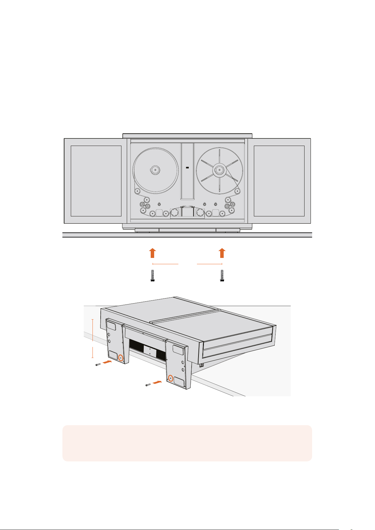
546mm
267mm
When desk mounted, you can securely fasten your scanner to your work surface by
screwing M6 safety bolts into your scanner’s feet.
NOTE Your safety is important to us and we strongly advise reading the warning
information on the following page before mounting your Cintel scanner.
5Unpacking and Mounting
Page 6
Wall Mounting
Cintel’s elegant industrial design and narrow profile make it ideal for wall mounting.
To do this, the first thing you’ll need to do is remove the feet and support strut from the base of
your scanner.
1 Place your scanner face up with its feet over the edge of a solid, stable surface capable
of supporting your scanner’s weight.
2 Unscrew the pair of M8 screws from each foot using a 6mm hex key, then gently
remove the feet.
3 Using a Phillips head screwdriver, remove the support strut between the feet. Store
the support strut in a safe place together with your scanner’s feet so you can always
reattach them later if you need to relocate your scanner.
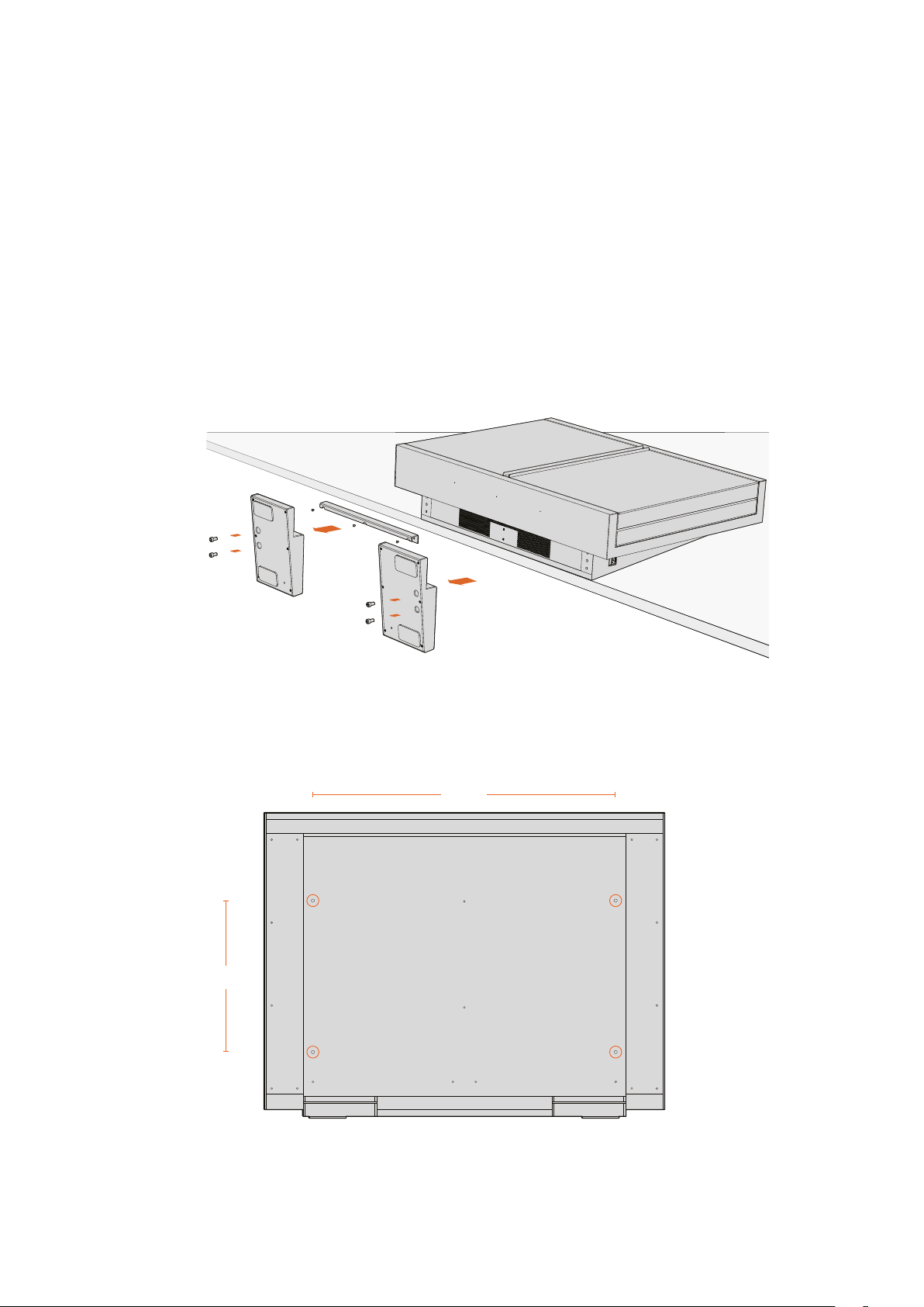
Your scanner’s desk mount feet and support strut can be removed
if you want to mount your scanner to a wall.
The locations of the four M8 mounting screws on your scanner’s back panel are shown below.
Be sure to use M8 screws when securing your scanner to a wall mount.
800mm
M8 M8
400mm
M8 M8
6Unpacking and Mounting
Page 7

Warning for Safely Installingyour Scanner
The Cintel Scanner weighs up to 70kg, or 155 pounds, when loaded with film. This is
significantly heavier than a large screen television. If you are unsure of the structural capability
of the wall or desk to support the total weight of the scanner and film loaded then you must
obtain the advice of a qualified engineer to correctly analyze the mounting to ensure safety.
Incorrect installation will result in the scanner falling which could cause serious injury or death.
When desk mounting the scanner, and especially when working underneath your scanner to
install the desk mounting screws, ensure that your work surface is flat and stable. Mounting
brackets and fixings must be of sufficient strength to securely support your scanner’s weight.
Ifyour work surface is incapable of supporting the scanner’s weight, or loses strength over
time, your scanner may fall, possibly causing serious personal injury.
When wall mounting the scanner, ensure that the installation location is strong enough to
support long term use. If its strength becomes insufficient over the course of long term use,
thescanner may drop, possibly causing injury. Do not install in places which are unable to bear
loads. Mounting brackets and fixings must be of sufficient strength to securely support the
scanner’s weight. If the strength of the installation surface is insufficient, the scanner may fall
down and personal injury may result.
Desk or wall mounting your scanner must be undertaken by more than one person. Do not
attempt installation on your own.
Getting Started
After unpacking and mounting your scanner, getting started is as simple as plugging in power,
connecting your computer via Thunderbolt, launching Blackmagic DaVinci Resolve, and lacing
your film. If you want to immediately see your scan on an external monitor, you can load film,
manually tension it, and output it to an HDMI monitor. To learn more about this, refer to the
‘lacing film,’ and ‘playback controls’ section of this manual.
Installing the Software
Capture controls for your scanner are located in
DaVinci Resolve’s film scanner panel, therefore,
the first thing you’ll need to do when you’re ready
to capture your scan is make sure DaVinci
Resolve is installed.
Your scanner comes with Blackmagic Cintel
Installer software including DaVinci Resolve, as
well as a DaVinci dongle allowing you to use the
full version of DaVinci Resolve.
You can use the packaged installer to get started,
however, we recommend downloading the latest
version of the Blackmagic Cintel Installer from the
Blackmagic Design support center at:
www.blackmagicdesign.com/support
This section shows you
how to get started with
your Cintel scanner, including:
■
Connecting Power
■
Connecting to a Computer
■
Installing and launching
the Software
■
Lacing Film
Once your download has completed, unzip the file and double click on the Blackmagic Cintel
Installer. This will open a setup folder. Now simply run the installer files contained within the
setup folder and follow the prompts to install the software on your computer.
7Getting Started
Page 8
Plugging in Power
Now that all the required software is installed on your computer, you’ll need to plug power into
your scanner so that you can lace up your film.
Power your scanner by connecting a standard IEC cable to the AC power socket on the lower
right side of the back panel. Your scanner’s power indicator LED will glow green when power
isconnected.
Connecting to a Computer
Connect your scanner to your Mac OS X or Windows computer via the Thunderbolt port on your
scanner’s lower right side. You can also connect to an external monitor via your scanner’s
HDMIport for focusing or preview purposes.
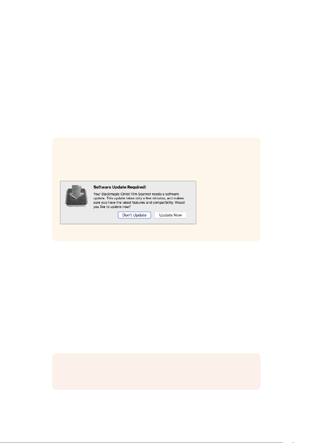
TIP If you have installed the latest Blackmagic Cintel Installer software, the next
timeyou connect your Cintel scanner to your computer it will prompt you to update
your scanner’s internal software. Simply follow the on screen prompts to complete
theinstallation.
Click on the ‘Update Now’ button to update your scanner’s internal software.
Launching DaVinci Resolve
Launch DaVinci Resolve and select the Media page. Open DaVinci Resolve’s film scanner panel
by clicking on the ‘capture’ button at the top right of the screen and selecting ‘film scanner’.
The scanner will capture a large amount of image data, so you’ll need to set the folder you want
DaVinci Resolve to record the captured files to.
To do this:
1 Launch DaVinci Resolve.
2 Click on ‘preferences’ in the DaVinci Resolve menu bar.
3 Click on the ‘plus’ icon in the ‘media storage’ tab.
Browse to and select a drive or folder path.
4 Click ‘save’, and restart DaVinci Resolve.
NOTE For detailed information on how to use all the control features in DaVinci
Resolve’s film scanner panel, refer to the section in this manual called “Capturing from
Cintel using DaVinci Resolve”.
8Getting Started
Page 9
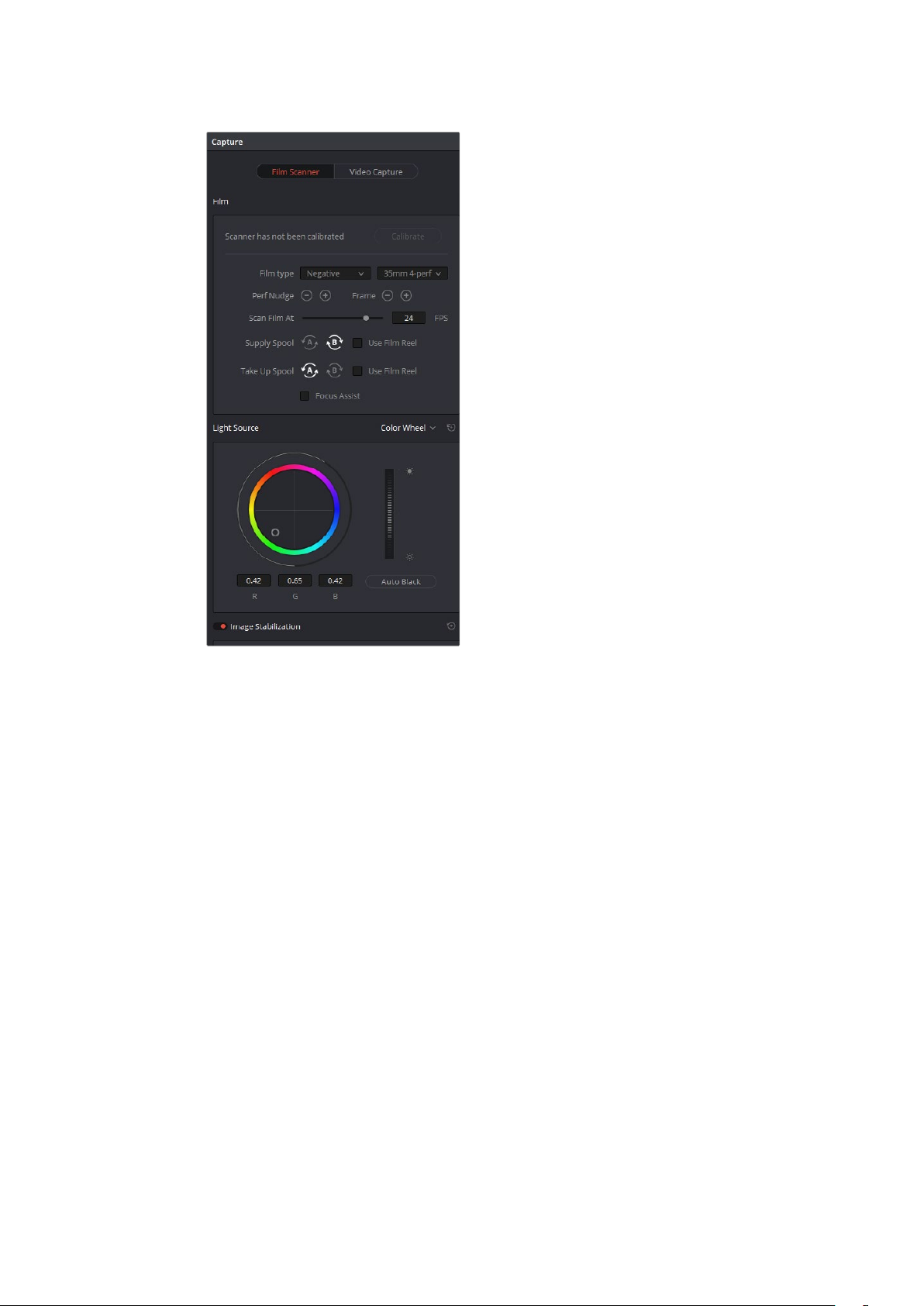
DaVinci Resolve’s film scanner panel
Resolve controls all capture settings.
Lacing Film
Now that your scanner and DaVinci Resolve are communicating with each other, you can lace
up your film.
1 Accessing the Scanner
Open your scanner’s sliding doors.
On the internal front panel you’ll see a feeding spool on the left, and a taking spool on
the right. The feeding spool holds the film to be scanned, and the taking spool collects
the scanned film.
2 Setting Film Wind
Set the ‘wind type’ so the spools turn in the appropriate direction. Go to DaVinci
Resolve’s film scanner panel and set the ‘wind type’ to B/A by clicking ’B’ and ‘A’
on the ‘feed’ and ‘take up’ buttons, respectively.
B/A is your scanner’s default wind type which has the feeding spool traveling in a
clockwise direction and the taking spool traveling counter clockwise. Refer to the ‘wind
types’ section in this manual for more information.
This is also a good time to make sure that your settings are appropriate for your film
type and size.
You can select from positive, negative, interpositive and internegative in DaVinci
Resolve’s film scanner panel, as well as 16mm, 35mm and various perforation layouts.
9Getting Started
Page 10
3 Preparing the Take up Spool
Slide the supplied 75mm spool core and core clamp onto your scanner’s taking spindle.
To apply the core clamp, hold in the clamp’s button and push it onto the spindle until
you feel resistance, then release the button and push the clamp on the rest of the way
until you hear a ‘click.’
4 Loading Film
Load your film reel or core onto the feeder spindle following the same procedure in
step 3. Note that the procedure differs slightly depending on whether your film is on a
core or a reel, and whether it is 35 or 16mm. For example, when loading a core, you’ll
need to insert the provided backing plate, whereas loading a reel only requires the use
of spacers.
When loading film reels, the backing plate is not required and you can simply use the
spacers provided. When loading f ilm on a core, the supplied backing plate is required.
5 Lacing Film
Gently lace several feet of the film leader through your scanner’s rollers following
theillustration on the next page.
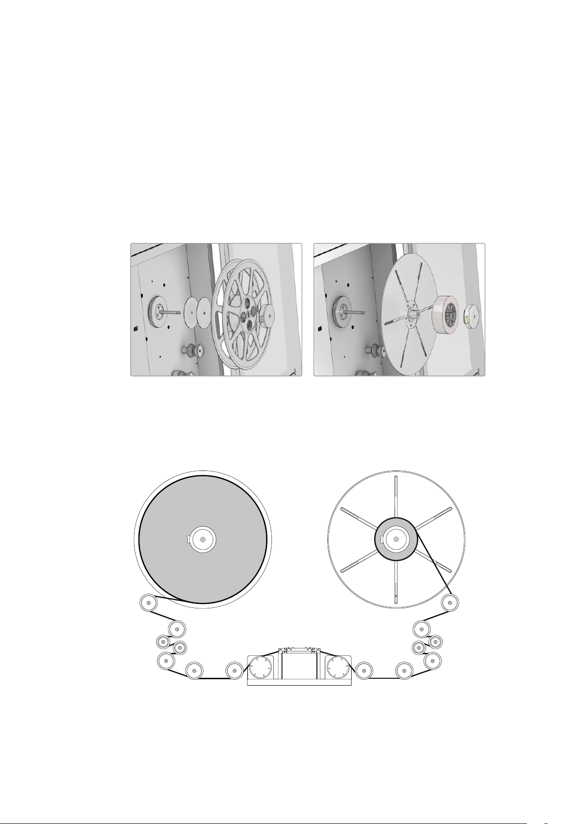
Your scanner’s default B/A wind loads from the bottom of
the feeding spool and onto the top of the taking spool.
10Getting Started
Page 11

NOTE The sprockets on the sprocket wheels are designed to fit 16mm and
35mm film. It’s important that your film is laced over the appropriate sprockets
so it glides smoothly over the skid plate, and that the sprockets are engaged
cleanly with the film perforations to ensure gentle film loading.
When loading 35mm film, use the outer
sprockets on the sprocket wheels.
6 Tensioning Film
To secure your film to the taking spool, insert the end of your film into the small notch
provided in the spool, then gently hand wind the spool a few times to hold the
film in place.
If you don’t want to bend the end of the film inside the notch, you can easily use the
friction of the film winding onto itself to secure your film to the spool. You can also use
very light adhesive tape.
Begin tensioning by pressing the ‘load button,’ or by manually turning the feeding and
taking spools simultaneously.
Manual Tensioning
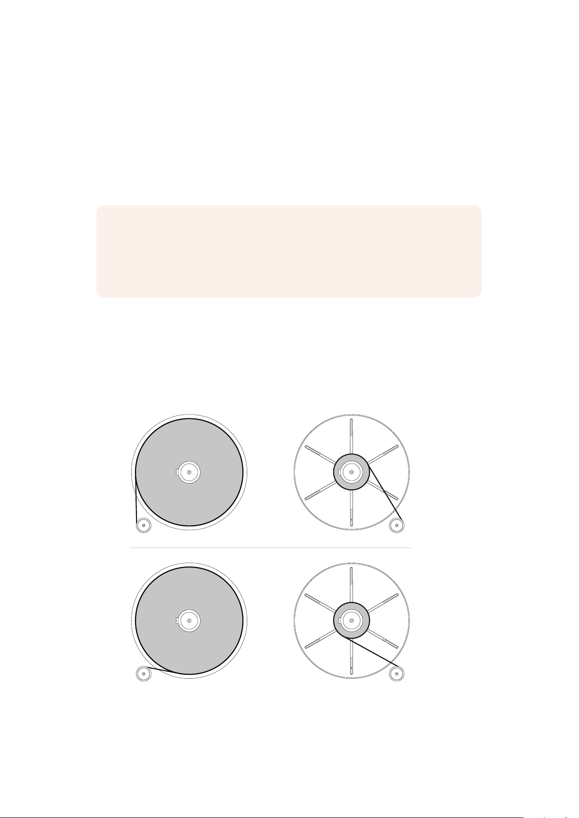
For manual tensioning, turn the feeding spool and taking spool counter
clockwise for a B/A wind.
You’ll notice the compliance arms below each spool begin to move as you
manually introduce tension as in the diagram below. Once these are about a
third of the way through their range of motion, hold the spools in place for a
second or two. Your scanner will detect secured film on the taking spool, and
its tensioning feature will automatically activate, taking up the rest of the slack.
If at any point in a manual or automatic load you notice a problem, you can
cancel the load procedure by pressing the ‘load’ button again or firmly holding
the feeding or taking spool.
11Getting Started
Page 12

Your scanner will recognise either action and abort the load.
When manually tensioning film, you only need to apply enough tension to
movethe compliance arms into the ‘sweet spot’ of their movement range alittle under half way. Your scanner will automatically take up any
additional slack.
7 Inspecting your Film
Check that the film is laced properly by pressing the ‘play’ button on your scanner or
clicking the ‘play’ button in DaVinci Resolve’s film scanner panel. If you see your film
image playing in the viewer, or on an HDMI monitor if connected, you’ll know your
scanner is working.
NOTE Depending on the wind type you’ve used, you may find that the image
is flipped horizontally or vertically. You can fix this by selecting the appropriate
film type. For instance, negative film may appear flipped left to right until the
‘negative’ setting is selected. If you can’t fix this by selecting your film type, you
may need to reload your film using a different wind type.
8 Focusing
Just like focusing the lens on a camera, you’ll need to focus the projected film image
onyour scanner’s sensor. The focus dial is located on your scanner’s center column.
The mostaccurate way to achieve perfect focus is to use the ‘focus assist’ feature in
DaVinci Resolve’s film scanner panel. Similar to the focus peaking feature in Blackmagic
cameras, focus assist displays a green edge around the sharpest points in your image.
This lets you easily adjust focus until the green highlights are at their strongest.
Simply turn the focus assist feature on by enabling the checkbox in DaVinci Resolve’s
film scanner panel, then watch the HDMI output from your Cintel scanner, or the viewer
in the film scanner panel, as you adjust the focus dial. Film grain is a terrific indicator.
When the grain in the film is registering the green edges at their strongest, your image
is in perfect focus.
12Getting Started
Page 13

Film grain is perfect for setting accurate focus using the ‘focus assist’ feature. In the above
example you can see the image out of focus on the left, and in focus on the right. The focus
assist feature can be seen highlighting the grain, most visible inside the perforation area.
TIP The focus assist feature works best when using negative film types,
asnegative is generally sharper with the most grain detail.
To get the most from the focus assist feature, set the viewer to full resolution.
Simply click on the options settings at the top right corner ofthe viewer and
select ‘Full Resolution Preview’ from the drop down menu.
It’s worth mentioning that full resolution preview will remain set until you choose
to disable it. The setting is very GPU intensive and can affect the performance
of the viewer, for example there may be some frame lag, soit may be helpful
tousefull resolution for checking focus, then turning it off for better performance.
9 Closing the Scanner Doors
For the best quality scan we recommend closing your scanner’s sliding doors. The
doors are designed to gently close when they are almost shut, so all you need to do is
slide them towards each other until you feel the spring mechanism take over. When
closed, the doors will block any light from entering the film gate.
TIP Your scanner’s high quality light source eliminates light pollution inall but
the most brightly lit workspaces. Because f ilm is quite shiny it can reflect lights
in the ceiling which may show up as blotches in your capture. You can avoid this
by keeping the scanner doors shut while scanning.
Now that you have laced your film, set the tension, focused your image and closed the scanner
doors, you can start capturing!
Please refer to the Cintel section of the DaVinci Resolve reference manual for details on calibrating
the light source, setting the stabiliser, and the capture palette settings for capturing images. The
DaVinci reference manual also details how to sync optical audio and shows how you can manage
your capture files when scanning.
If you are looking for information on how to maintain and service your scanner, including
detailed information about your scanner’s technical specifications, refer to the ‘Servicing’ and
‘Specifications’ sections near the end of this manual.
13Getting Started
Page 14
Using Your Scanner
Taking spoolFeeding spool
Feeding spool
Taking spool
Wind Types
The ‘wind type’ refers to the loading and unloading position, as well as the turn direction of film
on your scanner’s feeding and taking spools. As you can see in the diagram below, an ‘A’ wind
refers to film loading/unloading from the top of the spool, while a B type loads or unloads from
the bottom. This is true for both the feeding and taking spools.
NOTE The default wind type for your scanner is a B/A wind, meaning the feeding spool
unloads from the bottom and the taking spool loads across thetop. If the film you are
working with has been wound a different way, other combinations of A and B winds are
supported; simply select the appropriate wind type via the ‘feed’ and ‘take up’ buttons
in DaVinci Resolve’s film scanner panel.
Wind type affects which direction each spool turns, the position of the audio information and
perforations, and whether your film travels across the skid plate emulsion side up or down, so it
is important to use the appropriate combination for your project.
Select the appropriate wind type in DaVinci Resolve’s film scanner panel settings.
‘A’ wind
‘B’ wind
An easy way to remember the difference between A and B winds is that A winds unload and
take up film from the top of the reel or spool, while B winds do the same from the bot tom
14Using Your Scanner
Page 15
Switching to 16mm
The optional Cintel Scanner 16mm Gate kit contains all the parts you’ll require and making the
changes to your scanner’s setup are minimal.
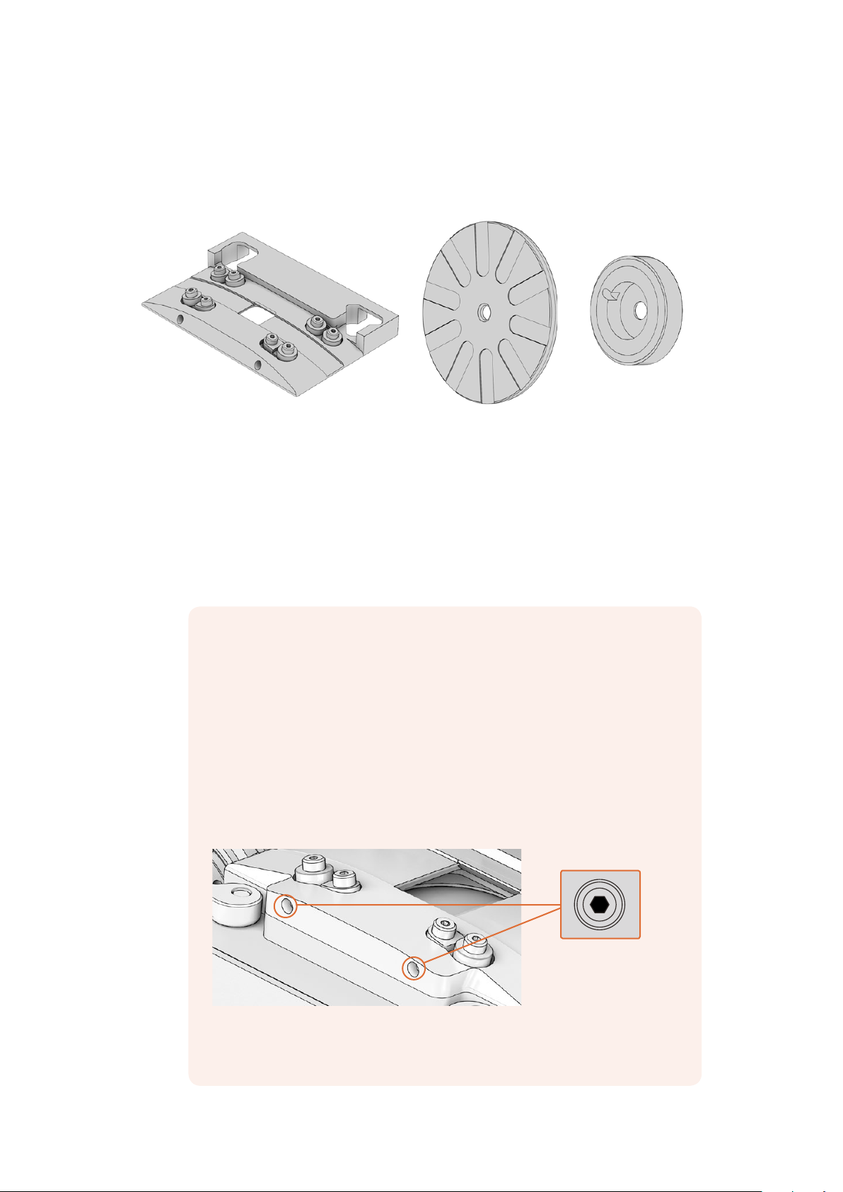
16mm skid plate Inner spacer Outer spacer
The 16mm kit contains a 16mm skid plate, two inner spacers and two outer spacers.
Switching to 16mm scanning is easy:
1 Swapping the Skid Plate
Swap the 35mm skid plate with the 16mm skid plate by pushing the retention levers
down on the front of the 35mm plate and turning them outwards. Now remove the
35mm plate and replace it with the 16mm plate. When fitting a skid plate, make sure that
the retention levers are lifted all the way up before turning them inwards, or the plate
may not seat properly.
Skid Plate Tension Screws
The four roller bearings on the skid plate keep the film moving in a defined
path and help to minimize gate weave. If some of the bearings are not making
contact with the film during a scan, their tension can be adjusted. To do this,
lightly tighten the M4 tension screws on the front of the plate using a 2mm
hex driver.
It’s worth mentioning that if too much tension is applied, it can slightly shift
theposition of the image on the skid plate, which may affect your scan. If this
happens, simply reverse your tension adjustments until your scan returns
to normal.
The skid plate tension screws are located at the front of both
the 16mm and 35mm skid plates.
15Using Your Scanner
Page 16
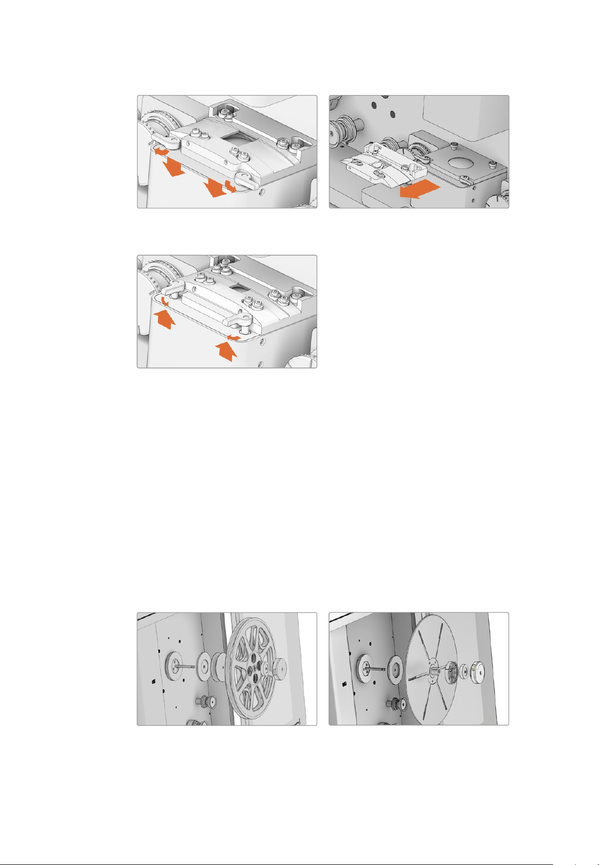
When removing the skid plate you will need to
push the retention levers down and then turn
them outward.
To secure a skid plate lift the retention levers
all the way up and turn them inward.
Removing the 35mm skid plate.
2 Inserting the 16mm Inner Spacer
Insert the rubber 16mm inner spacer at the base of the feeding and taking spools.
The rubber spacer goes on grooved side inwards prior to a backing plate, spool or reel.
3 Additional Spacers (optional)
Additional 1mm rubber spacers are included in the 16mm Gate Kit for when mounting a
reel. You can use these spacers if you need to adjust the alignment of the film with your
scanner’s rollers.
4 Mounting your Film
After mounting your 16mm core or reel to the feeding spool, and a backing plate and
core to the taking spool, you’ll need to install the outer 16mm spacer to secure the
spools. This spacer has both a notch and a rubber ring on its inside edge to secure it to
cores or reels, respectively. Once this is in place, secure the spools as you
would normally.
Reel mounting. Shown from spindle outwards:
inner 16mm spacer, 1mm spacers, 16mm
reel, outer 16mm spacer and core clamp.
Core mounting. Shown from spindle outwards:
inner 16mm spacer, backing plate, 16mm
core, outer 16mm spacer and core clamp.
16Using Your Scanner
Page 17
5 Lacing
Complete the lacing procedure as you would for 35mm film, with the exception of
lacing your 16mm film through the inner sprockets on the sprocket wheels. Before
pressing ‘load’ or manually tensioning your 16mm film, make sure that the film is
properly threaded over the sprocket wheels’ teeth, as otherwise these teeth can
damage the film.
When loading 16mm film, make sure the
film’sperforations are threading cleanly over
the sprockets on the sprocket wheels.
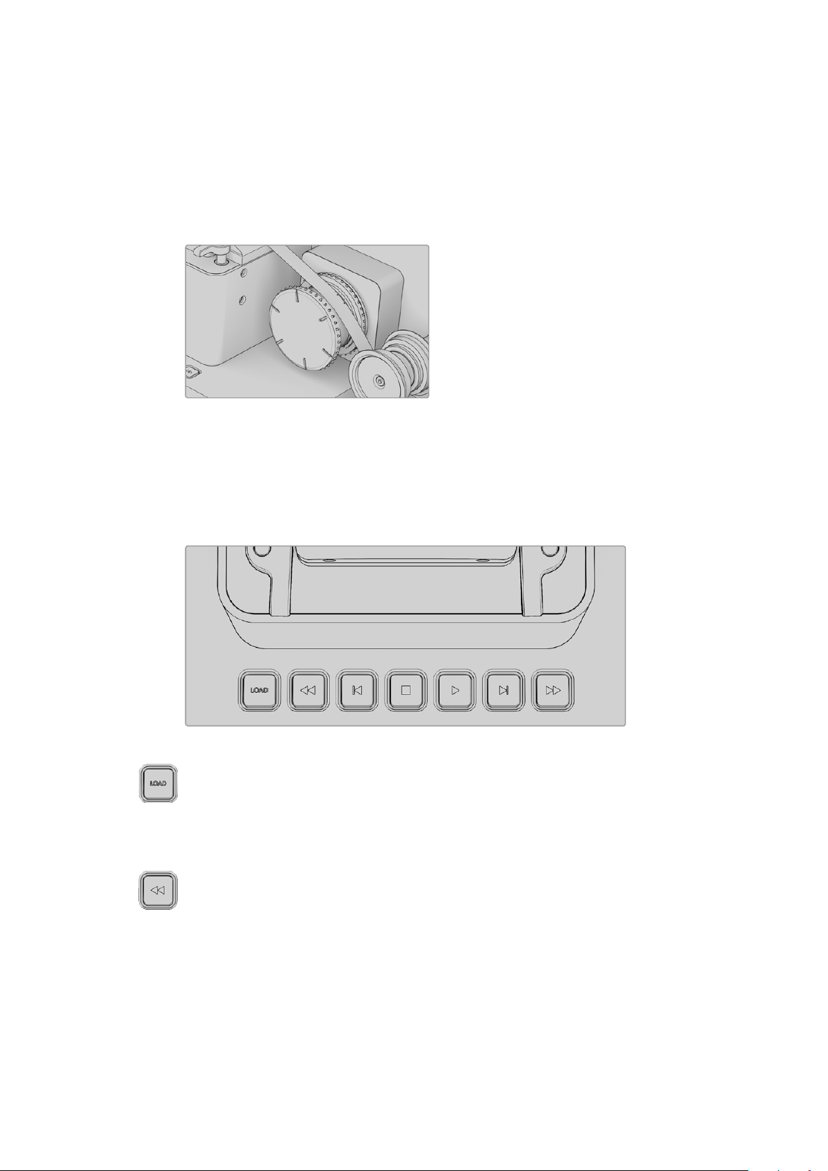
Playback Controls
The following playback controls are available in DaVinci Resolve and on your scanner.
Your scanner has built in controls for loading, unloading, and previewing scans.
Load
Pressing ‘load’ will tension the film loaded onto your scanner’s feeding and taking
spools as described in the section ‘lacing film.’
Pressing load once your film is properly tensioned will unload the film by returning the
compliance arms to their slack position.
Rewind
Press rewind to wind your film back onto the feeding spool. Pressing this button once
will rapidly rewind your film until it reaches the threshold of a fully loaded 75mm spool,
at which point it will stop. Press rewind again to slowly wind the rest of your film all the
way onto the feeding spool and unload your scanner.
If you are using a 50mm spool, your scanner will initially stop at the 75mm threshold.
Pressing rewind a second time will then slowly rewind until the point a 75mm spool
should have been fully rewound. If your scanner detects f ilm still loaded at this point,
itwill resume rewinding quickly until reaching the 50mm threshold, where it will stop
again. Press ‘rewind’ a third time to completely rewind a 50mm spool.
17Using Your Scanner
Page 18

Due to the rarity of 100mm spools, your scanner is not programmed to stop prior to
hitting the 100mm threshold. If you are using a 100mm spool, take care with your
method of loading film onto the taking spool. Please use the provided notch, or if you
don’t want to bend the end of the film inside the notch, you can use friction from the
film winding onto itself. Avoid using adhesive tape when loading 100mm spools to
make sure your spool unloads cleanly.
Step Back
Rewinds the film one frame. You can also hold down the ‘step back’ button to play
thefilm backward at slow speed.
Stop
Stops playback, fast forward and rewind.
Play
Plays the film. The default frame rate is 24 frames per second, however you can set
theplayback frame rate in DaVinci Resolve’s film scanner panel.
Step Forward
Advances the film one frame. You can also hold down the ‘step forward’ button to play
the film forward at slow speed.
Fast Forward
Rapidly advances the film onto the taking spool. The stopping action performs
thesame way as rewind for 50, 75 and 100mm spools.
Standby Mode
When inactive, your scanner will enter standby mode to preserve the longevity of the light
source. This happens after 15 minutes when connected via Thunderbolt, or 1.5minutes when no
software is connected. Your scanner will signal that it is entering standby mode by flashing the
light source green.
Capturing from Cintel
usingDaVinciResolve
This section of the manual shows you how to use settings and features in DaVinci Resolve’s film
scanner panel to control your scanner. For example calibrating your scanner, adjusting thelight
source strength and color temperature, setting image stabilization, and more. You can even set
how gentle your Cintel scanner handles film which may have become delicate with age.
18Capturing from Cintel usingDaVinciResolve
Page 19

The Cintel Scanner Interface
Click on the ‘capture’ button in the UI toolbar at the top of the DaVinci Resolve screen to set the
media page to control your Cintel scanner. Open DaVinci Resolve’s film scanner panel to set up,
calibrate, and choose options for logging or scanning a selected range of the currently spooled
roll of film. If you want more room for viewing the Cintel scanner controls, click the full height
button that’s all the way to the right of the UI toolbar, and turn off the ‘metadata’ panel.
Cintel scanner controls in the Media Storage page
Transport Controls: The transport controls under the viewer, while similar in
appearance to those used while in playback mode, now work to control the Cintel
scanner. Additional controls appear for moving forward or backward a frame at a time.
In and Out Controls: In Cintel Scanner mode, the In and Out buttons to the right of the
transport controls define a range of the film roll from which to capture.
The following groups of settings appear to the right of the ‘media’ page viewer when in
CintelScanner mode to scan clips from film into the media pool.
Calibration
This option lets you calibrate the optics of the scanner to eliminate optical blemishes or dust
that cannot be removed. Please note that this feature does not remove dust from the film itself.
The calibration button can be used to help remove dust or small
blemishes from the optics of your Cintel scanner.
Calibrate button: This button lets you eliminate light optical blemishes and dust from
the optics of the Cintel scanner via digital calibration. While it’s recommended to “spray
dust” the optics before scanning new material, it’s possible over time for some
blemishes on the optics to be unremovable, in which case using the calibrate button
will eliminate them from the scanned image.
The skid plate does not normally need to be removed for calibration, however, in cases
where there is severe dirt, remove the skid plate, dust it, and then reinstall it. Use the
‘calibrate’ button before you load film into the scanner, while there’s nothing in the
optical path, to remove any remaining optical blemishes or dust.
19Capturing from Cintel usingDaVinciResolve
Page 20
TIP Calibrate the optics with the skid plate installed and correctly aligned, as
this assists with image stabilization and offers the best image quality.
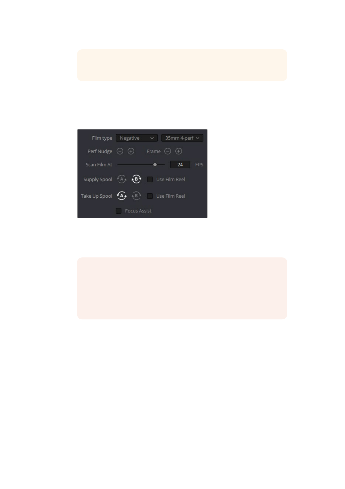
Film Type
These controls let you select the type of film you’re scanning, align the film with the sensor, and
choose what speed you’re scanning at.
Film Type controls in the Media page
Film Type pop-up: Lets you choose what type of film you’re scanning. The choices are
Positive, Negative, Interpositive, and Internegative.
NOTE When scanning interpositive and internegative film, the increased
density of the film requires slightly extended pulse durations from the light
source. Normally, this does not affect the scan, however, a slight reduction in
resolution may occur when scanning at above 12 frames per second. Ifyou do
notice a difference in resolution, simply reduce your scanning speed to 12
frames per second or less.
Gauge and perf count pop-up: Lets you choose what reel type you’re scanning, the
choices are 35mm 2, 3, and 4 perf, and 16mm.
Perf nudge buttons: Used for making fine adjustments of the perf position relative to
the scanner gate aperture. Command-J nudges up, while Command-L nudges down.
Frame buttons: These buttons are push and hold to activate. When on, the film is
slowly advanced to move the frame up or down and when released the film stops in
place. This is useful for aligning the film frame with the scanner’s sensor. Using the ‘perf
nudge’ and ‘frame’ buttons, you want to align the visible film frame so the bottom of the
previous frame and the top of the next frame are just visible at the top and bottom of
the viewer, and the current frame is centered vertically.
It’s important to make sure the image in the viewer is not zoomed in when you do this.
Command-Left Arrow on your keyboard moves the frame up, while Command-Right
Arrow moves the frame down.
20Capturing from Cintel usingDaVinciResolve
Page 21
Scan Speed slider: With adequate disk performance, you should be able to scan at
30fps. However, if you’re scanning to a slow hard drive, you can reduce the scanning
speed to a frame rate that’s suitable for your workstation without dropping frames.
Supply buttons: Sets the wind direction of the left-hand side feed spool. While auto-
detection will prevent incorrect operation, you should manually configure the reel
winding direction based on how each film roll is wound.
Take up buttons: Sets the wind direction of the right-hand side take up spool. While
autodetection will prevent incorrect operation, you should manually configure the reel
winding direction based on how each film roll is wound.
Use Film Reel checkboxes: Small film reels have a different weight and inertia
compared to large film spools, and this can affect the transport system. Tick this box to
switch to settings that offer improved stability for small film reels.
Focus Assist checkbox: Enables luminance peaking on your scanner’s HDMI monitor
output, plus the viewer inside DaVinci Resolve’s film scanner panel, which makes it
easy to obtain optimum focus adjustments.
Light Source
These controls let you adjust the scanner’s light source to adjust the optimal Dmin, which is the
minimum scanned signal value, plus the color temperature of the scanned material. Use the built
in software scopes in DaVinci Resolve to help set your light source to its optimum level settings.
Scopes can be opened in the Media page by choosing Workspace > Video Scopes > On. You can
adjust these settings to make sure you’re not clipping image data during the scanning process.
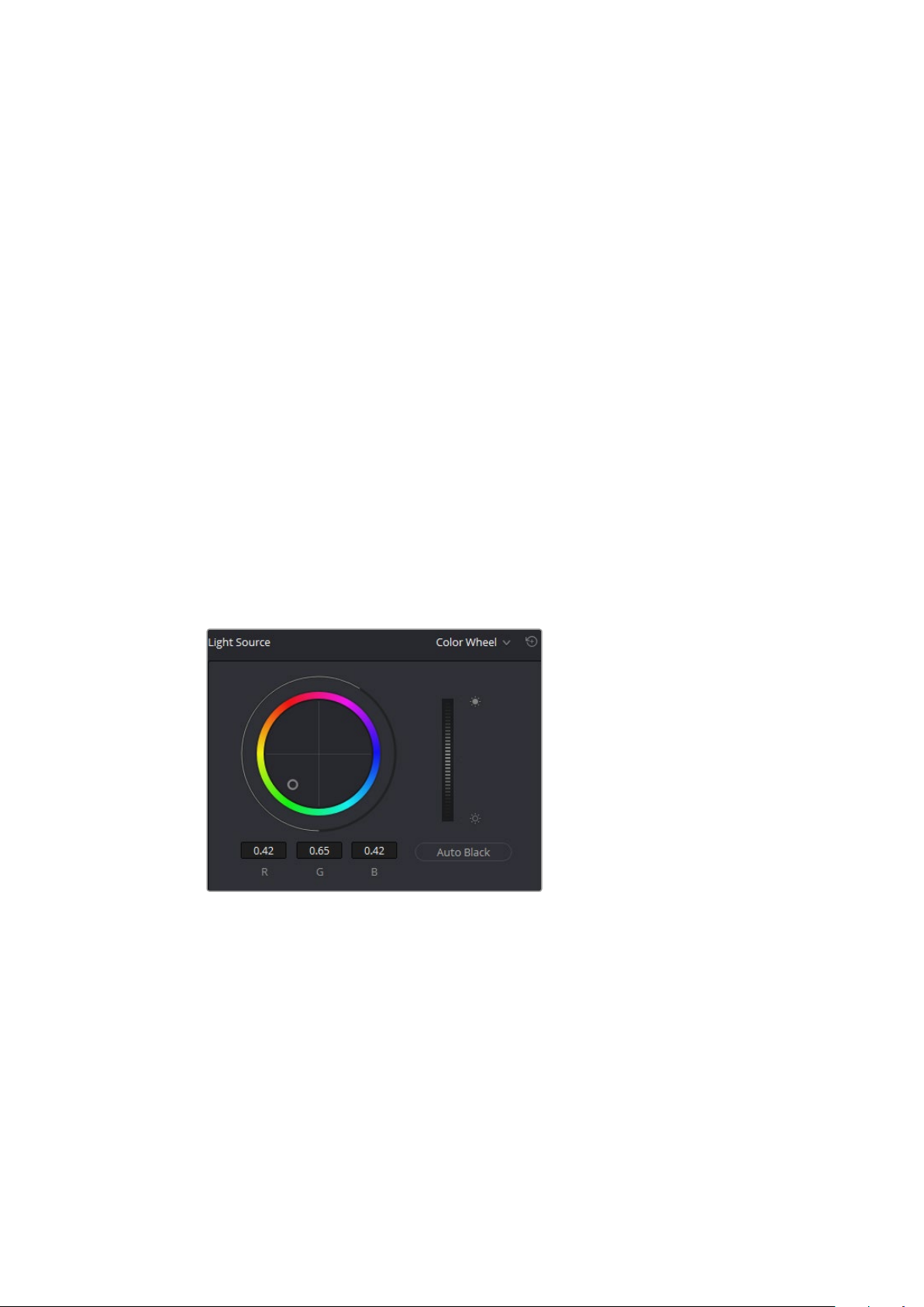
Light Source controls in the Media page
Light Source master wheel: The vertical light source master wheel is located next to
the color wheel and adjusts the intensity of the light source used to illuminate the film,
raising or lowering the RGB channels all at once. For typical negative film, this lets you
adjust the black point of the film image, which is the darkest part of the image. In
negative f ilm, this in fact corresponds to the highlights of the film image. Adjust the light
intensity to sit just above the typical Dmin value of 95, as measured on the histogram
ofthe video scopes, which guarantees that the highlights won’t be clipped by a
Cineon-style LOG conversion. For positive film, simply adjust the master wheel so that
no part of the signal is being clipped.
Auto Black and Auto White button: Analyzes the current frame displayed in the viewer
and does an automatic adjustment to set the black point for negative, or for print to set
the white point. For positive film types, the ‘auto black’ button changes to ‘auto white’.
21Capturing from Cintel usingDaVinciResolve
Page 22
RGB controls: By default, a color balance control lets you adjust all three color
channels by varying amounts to alter the color temperature of the light source used to
illuminate the film, while the adjusted R, G, and B values are displayed in three fields
below. Optionally, you can choose to put this control into ‘color bars’ mode using the
mode pop-up to the right of the ‘light source’ title bar, which changes this control to
three vertical red, green, and blue color channel sliders.
Image Stabilization
These controls let you enable and disable as well as control image stabilization to eliminate
vertical film hop.
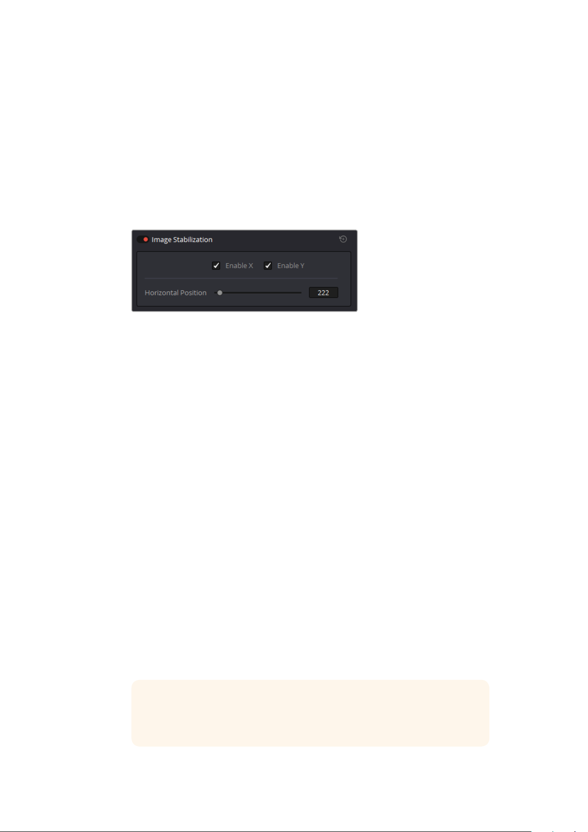
Image Stabilization controls in the Media page
Image Stabilization enable/disable control: The dot to the left of the ‘image
stabilization’ title bar lets you enable or disable your scanner’s hardware-based image
stabilization altogether. While hardware stabilization is typically desirable when you
have high quality perforations, you may want to turn this option off if the condition
ofthe perforations is poor and you decide to use DaVinci’s software based
stabilization instead.
When image stabilization is enabled, a horizontal X axis detection overlay is displayed
in the viewer, highlighting the edge of the film perforation that will be used as the
reference for stabilization. This overlay is automatically hidden when recording. Image
stabilization is enabled by default.
Enable X and Y checkboxes: Enable X and enable Y lets you choose whether to use
hardware image stabilization to fix horizontal gate weave and vertical gate hop
respectively. If the results are unsatisfactory with both axes enabled, you can turn off
the axis that’s causing issues with stabilization.
Horizontal Position slider: Your Cintel scanner attempts to automatically place the
stabilization detection overlay at the best location, with reference to the perforation
shown on the currently loaded frame, for the best stabilization result.
You will notice a thin transparent line in the blue alignment overlay. For optimum
stabilization, this line should touch the edge of the perforation. If the automatic
positioning is not ideal, you can manually move the overlay to a more ideal position,
either by dragging it in the viewer with your mouse, or by using the horizontal slider.
Ideal placement of the stabilization overlay should position the clear line in the alignment
overlay on the edge of the perforation, as shown in the example image. With the overlay
correctly positioned, this enables hardware stabilization of gate weave along the X axis.
TIP Image stabilization automatically manages vertical gate hop when you
select the ‘enable y’ checkbox. It needs no further adjustment and works in
conjunction with horizontal stabilization.
22Capturing from Cintel usingDaVinciResolve
Page 23
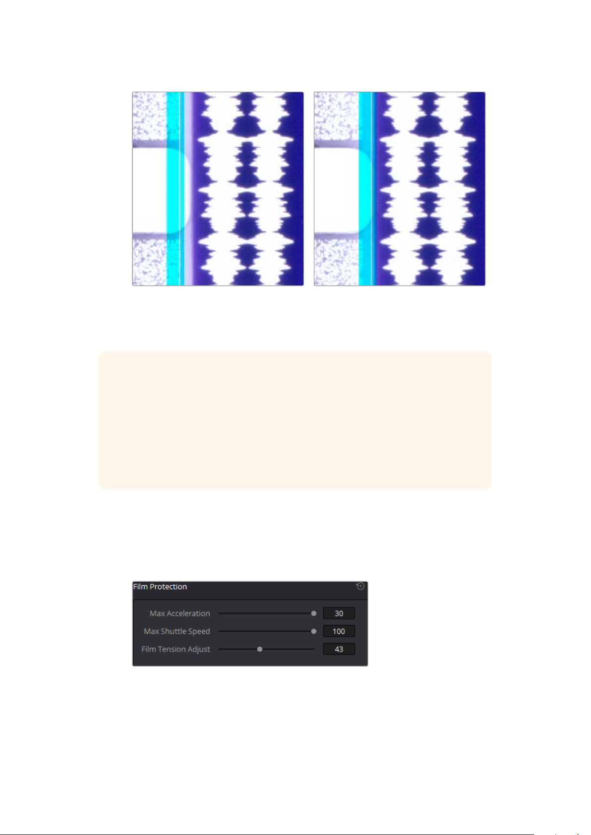
Adjusting the horizontal position of the
stabilization overlay. In this screenshot,
theoverlay is not alignedwith the edge
of the per f.
Hardware stabilization control correctly
positioned over a perforation in the viewer.
The transparent stripe in the stabilization
overlay touches the edge of the perforation.
TIP To closely check the results of your stabilization settings before capturing, set the
viewer to full resolution. Simply click on the options settings at the topright corner of
the viewer and select ‘Full Resolution Preview’ from the drop down menu. This setting
does not affect the stabilization feature, but enables the best possible preview so you
can monitor how well it is performing.
It’s worth mentioning that this setting will remain set until you change it back toyour
previous setting. Full resolution is very GPU intensive and may result in some frame lag.
For best performance, turn full resolution off after checkingstabilization.
Film Protection
These controls are intended to allow delicate film to be handled gently by the Cintel Scanner.
Fast acceleration and shuttle speeds can be hard on archival footage, so it’s recommended to
lower both of these sliders from their defaults whenever you’re scanning older film.
The ‘Acceleration’ and ‘Shuttle Speed’ sliders should be
lowered when scanning older, delicate archival film
Max Acceleration: Changes the scanning speed to operate between 5–30 frames per
second per second.
23Capturing from Cintel usingDaVinciResolve
Page 24
Max Shuttle Speed: Changes the speed of shuttling from one section of film to another
between 1–100 frames per second for 35mm film, and between 1–200 frames per
second for 16mm film.
Film Tension Adjust: This setting gives you the ability to adjust the amount of tension
applied to 35mm film. For example, when loading delicate archival film, or
compensating for film shrinkage.
NOTE It’s worth mentioning that there is no possible way you can damage the film
using the Film Tension Adjust setting. The adjustment values are very small and only
gentle changes are all that’s required to prevent sprocket picking.
Editing Capture Info Metadata
When DaVinci Resolve is used in conjunction with Cintel Scanner, a set of capture metadata
fields appears at the bottom of DaVinci Resolve’s film scanner panel. The ‘capture info’ panel
has editable metadata fields that describe capture properties such as where to save files, the
type of codec, frame rate, and the format of file names. This metadata is attached to your clips
and can be read on the media page.
Before you begin scanning, you may want to adjust some of the project settings.
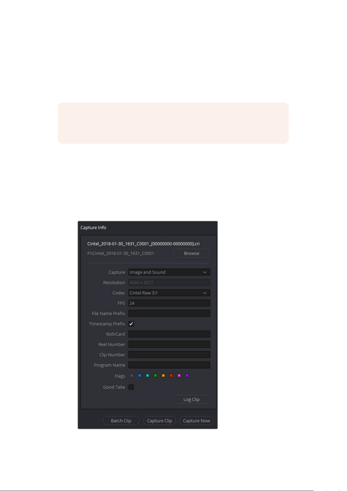
The ‘capture info’ panel lets you specify metadata for your scanned clips
24Capturing from Cintel usingDaVinciResolve
Page 25

Capture Location: Before you begin a film scanning session, scroll down to the
‘capture info’ section of DaVinci Resolve’s film scanner panel to make sure the scanned
files are being saved to the directory and volume where you want them. Click the
‘browse’ button and choose a location from the file destination dialog. It’s good to do
this first, as this step is easy to forget.
Capture: When you have a Cintel Audio and KeyKode Reader fitted, this menu gives
you options for ‘audio only’ so no images will be captured, or ‘image and sound’.
Alternatively, you can capture ‘image only’ if audio is not important.
Resolution: The resolution of the capture files depends on the source film format so
this field cannot be edited.
Codec: DaVinci Resolve selects the ‘Cintel Raw’ codec for lossless compression
bydefault, or you can choose ‘Cintel Raw 3:1’ for even smaller file sizes.
FPS: This sets the frame rate of the film itself and Resolve automatically adjusts the
timeline frame rate based on this.
TIP When using the optional Audio and KeyKode Reader accessory to scan
audio, the reader will automatically adjust for frame rate to maintain an overall
sample rate of 48kHz.
File Name Prefix: Prefix to help identify the scan. This can be the name of your project,
such as the title of the film you are scanning.
Timestamp Prefix: Select this checkbox to prefix your scans with a timestamp as well
as the ‘file name prefix’ you specified. Your clips will be saved to independent subfolders in the destination folder. This checkbox is selected by default.
If you want to save all your clips together in one master destination folder without the
timecode in the file name, simply deselect the checkbox.
NOTE If you don’t make capture names unique with the timecode prefix and
the files go into the same location, this could potentially overwrite files.
Roll/Card, Reel Number, Clip Number, and Program Name: These are ways
toidentify the clip with metadata.
Flags: You can use these color coded flags to tag clips.
Good Ta ke: Corresponds to ‘circled take’ metadata in the media pool.
Log Clip: Adds a clip to the media pool. After you mark ‘in’ and ‘out’ points for a section
you want to scan, confirm the metadata is correct, and then click ‘log clip’. For more
information, refer to the ‘Logging and Capturing Individual Clips’ and ‘Logging and
Capturing Multiple Clips’ sections in the DaVinci Resolve manual.
Batch Clip, Capture Clip, and Capture Now: These scanning buttons offer different
methods to capture clips. For more information about scanning buttons, refer to the
‘Scanning One or More Sections of Film’ section of this manual.
25Capturing from Cintel usingDaVinciResolve
Page 26

Film Scanning Workflows
The following sections describe how to scan film using DaVinci Resolve and to control the
Cintel scanner. Throughout, the features outlined in the previous section are presented in
the order in which you’ll perform each step of the scanning process.
Before You Begin
Before turning your scanner on and loading film, you should first dust the gate to make sure
your scans are as clean as possible. This can be accomplished using compressed air, but if
the gate is extremely dirty, you can remove it to give it a more thorough cleaning. Once that’s
finished, turn on the Cintel Scanner, open DaVinci Resolve and create the project you’ll be
using to scan film, and then click the ‘Cintel scan’ button on the media page. Now click the ‘Film
Scanner’ tab to select DaVinci Resolve’s film scanner panel.
Before you load film into the scanner or do anything else, click the ‘calibrate’ button at the
bottom left of the film scanner panel. While you should always dust the gate of the scanner
before loading a new reel of film, clicking the calibrate button eliminates any unremovable
blemishes in your scanner’s optics from the scans you’re about to make.
Load and Align the Film
Load the film you want to scan. In the presence of an image the scanner will automatically align a
frame. You should note that the image may be framed incorrectly if you first load blank film leader.
Next, choose the f ilm type. If necessary, use the ‘perf nudge’ and ‘frame’ buttons to manually
improve the alignment of the framing bar to the scanner’s sensor such that the bottom of the
previous frame and the top of the next frame are just visible at the top and bottom of the viewer,
and the current frame is centered vertically. It’s important to make sure the image in the viewer
is not zoomed in when you do this.
Focus the Scanner
Just as you need to focus the lens on a camera, you’ll need to focus the projected film image on
your scanner’s sensor. To achieve perfect focus, turn on the Focus Assist checkbox in the Film
Scanner capture settings of DaVinci Resolve. This superimposes a focus peaking overlay over
the Ultra HD image that’s output from the scanner’s HDMI output, and is also displayed in
DaVinci Resolve’s capture window. For the best results, connect an Ultra HD display to your
Cintel scanner so that you can monitor at the maximum available resolution while you focus.
With Focus Assist turned on, focus peaking will detect the film grain of the scanned image
whenever the film plane is in perfect focus. This enables the operator to focus the scanner even
if the film image is out of focus. Simply monitor the Ultra HD output of the scanner while you
turn the Cintel scanner’s focus wheel. Your image will be in focus when the grain running
throughout the image displays peaking outlines.
TIP You can verify the focal adjustments you’ve made by checking the edges of your
film’s perforations. When these are sharp, your film will be in focus.
26Capturing from Cintel usingDaVinciResolve
Page 27

Reset the Timecode
To set the timecode for the roll of film you’re about to scan, you need to locate the zero frame for
that roll. It’s standard practice to punch a small physical hole within the frame before the first frame
of necessary film on a roll, to use as a permanent reference for whenever that roll is scanned. This is
referred to as the marker frame, lab roll hole, or head punch. By always setting the first frame of
timecode to match the marker frame, subsequent film scans will have the same frame count as
previous scans, making it possible to rescan and reconform the same material whenever necessary.
To reset scanned timecode at the marker frame of a new film roll:
1 Use the transport controls under the viewer to locate the marker frame.
2 Click the ‘viewer’ option menu and choose ‘current frame timecode.’
Choosing Current Frame Timecode
from the Viewer Option menu
3 Enter a timecode value in the dialog box that appears. For example, if you’re scanning
the first roll of a project, you can enter 01:00:00:00.
The Set Current Frame Timecode dialog
4 When you’re done, click OK.
Timecode cannot be a negative value, so don’t set the start frame to zero. Another common
organizational technique is to change the hour number whenever you change rolls, to coincide
with the film roll’s number, which makes it easy to identify a scanned clip with the corresponding
source roll and frame range.
NOTE Your Cintel Scanner has built in ‘Options Interface’ ports for adding optional
hardware in the future. This offers the ability to add optional featuressuch as reading
KeyKode from the camera negative. It also gives you the ability to scan optical audio in
real time while you are scanning the picture.
27Capturing from Cintel usingDaVinciResolve
Page 28

Choose a Location to Save the Scanned Frames
Once all this is done, scroll down to the ‘capture info’ controls in DaVinci Resolve’s film
scannerpanel, and click the ‘browse’ button to choose a location for the scanned files.
Youcanuse the other fields in this section to set what prefix you want to add to the name of
the scanned files and enclosing folders. The ‘file name prefix’ updates the file name preview
that’s shown at the top in the header. The header also shows the file path, resolution, frame
rate, duration, and the format. Specify what roll, reel, clip, and program information you want
associated with the scanned media. The ‘timestamp prefix’ checkbox in the ‘Capture info’
controls is selected by default and will save your clips to independent sub-folders within the
destination folder, together with a timecode prefix in the file name.
If you want to save all your clips together in one master destination folder, simply deselect
the checkbox.
Check the Codec
DaVinci Resolve selects the ‘Cintel Raw’ codec by default, or you can choose ‘Cintel Raw 3:1’.
The Cintel Raw Format
The Cintel Raw Format Bayer pattern of each film frame scanned with your Cintel
scanner’s sensor is saved with embedded scanner metadata as a 12-bit linear Cintel
Raw Image, or CRI, image sequence. When grading in DaVinciResolve, CRIimages
areautomatically debayered as 12-bit log encoded image data.
The logarithmic encoding is similar, but not identical to, Cineon encoding. Forexample,
negative film is encoded using a Gamma of 2.046 for density, while print film is encoded
using a full range Gamma 2.2 curve to ensure that no image data is clipped. Both of
these logarithmic encodings can be converted to a linear color space using the ‘Cintel
toLinear’ 1D LUT, before converting to other color spaces you may want to work in.
The film is scanned using the full sensor aperture of 4096x3072 for a 35mm or16mm
image. This keeps the audio waveform visible for optical audio and to accommodate
perforation visibility for stabilization. 16mm is cropped to 2304x1712. The resolution
ofthe capture files depends on the source film format after overscan for perforations
andthe audio area are removed. Super 35 film is captured to Ultra HD at 3840x2880
pixels, while Super 16 scans at nearly HD resolution with 1903x1143 pixels. The Cintel
scanner creates Cintel Raw files with variable bitrate lossless compression by default.
Thisis visually lossless compression and achieves a 3:2 reduction in file size. However,
Cintel Raw 3:1 uses lossy compression with a ratio of approximately 3:1. This is still very
high quality but may not always be visually lossless. For example, files for 35mm 4 perf
are approximately 12.5MB with Cintel Raw and approximately 6.3MB with Cintel Raw 3:1.
Files for 16mm are approximately 4MB with Cintel Raw and approximately 2MB with
Cintel Raw 3:1.
Cintel Raw Image files don’t have dedicated debayering controls in DaVinciResolve.
Tocontrol the quality of debayered CRI files, use the ‘decodequality’ and ‘play quality’
CinemaDNG settings located in the CameraRaw panel of the project Settings.
28Capturing from Cintel usingDaVinciResolve
Page 29

Adjusting the Color of the Scanner
DaVinci Resolve’s film scanner panel gives you control over the exposure and color
temperature of the light used to illuminate the film for scanning. You can adjust these via the
light source master wheel and RGB controls, in order to maximize the amount of information
you’re extracting from each frame, while preventing any part of the image from being
irretrievably clipped. While it’s true that CRI is a raw image format, there’s no latitude beyond
the internal data range used by DaVinci, so be mindful that if you’re clipping data in the built in
video scopes while scanning, it might be clipped permanently in the scanned media.
How often you’ll adjust the color and exposure of scanned shots depends on how much variety
there is in the scenes on a particular film roll. For example, some rolls may have many takes of
the same scene, all of which have the same lighting and which can share the same adjustments.
Meanwhile, other rolls may have a variety of different scenes with widely different lighting in
each one, necessitating you to make individual adjustments for each scanned clip to maximize
data quality.
This is important because the light source master wheel and RGB controls cannot be
automatically changed between scanned clips in a log and capture workflow. This means that the
current light source settings will be used for all clips you scan until you manually change those
settings again, even for clips that you’ve logged from different parts of a film roll. This means
that the log and capture style of working is only advisable in situations where it makes sense to
log multiple clips that share the same light source master wheel and RGB control adjustments.
Otherwise, it’s recommended you make lighting adjustments on a clip by clip basis, as you scan
each clip, in situations where you need maximum image quality for finishing. Keep in mind that
the goal for these adjustments is to maximize image data from the scan, not to create the final
look of the clips, which you’ll accomplish later in the grading phase of work using the controls of
the ‘color’ page.
To adjust the light source settings, find a typical image for the section of roll or for the first series
of shots you’re going to scan, and adjust the light source while viewing the built in video scopes.
Adjust the light source master wheel to set the intensity of the light source used to illuminate
the film, raising or lowering the level of the R, G, and B channels all at once. For a typical
camera negative, this lets you adjust the black point of the film image. In a negative print, the
darkest part of the image corresponds to the highlights of the film image. Set the light source
master wheel to sit just above the typical Dmin value of 95, as measured on the histogram of
the video scopes, which guarantees that the highlights won’t be clipped by the Cineon LOG
conversion that DaVinci uses to debayer the CRI image for grading. For positive film, simply
adjust light source so that no part of the highlights or shadows of the signal is being clipped.
TIP You can turn on ‘show reference levels’ in the waveform, RGB parade, orhistogram
scopes, and set the ‘low’ value to indicate the digital Dminvalue of 95.
Once that’s accomplished, adjust the RGB controls to rebalance all three color channels by
varying amounts to alter the color temperature of the light source used to illuminate the film,
toproduce the most useful, or neutral, color balance in the scanned result.
29Capturing from Cintel usingDaVinciResolve
Page 30

Scanning One or More Sections of Film
After you’ve adjusted the light source, it’s a good idea to stay organized as you scan each clip
by entering all relevant metadata into the metadata editor as you go. The ‘capture info’ group
ofmetadata fields contains information for defining the file name prefix, roll, reel number, clip
number, program name, flags, and whether a particular take is good. If you populate these
fields before scanning a clip, that metadata will be written into the clip.
At the bottom of the ‘capture info’ panel, you will see three buttons for film scanning, ‘capture
now’, ‘capture clip’, and ‘batch clips’. For more information about these scanning methods, refer
to the ‘Three Methods of Capture’ section in the DaVinci Resolve manual.
With all of this accomplished, you can scan clips from film in one of three ways:
Capture Now: Clicking ‘capture now’ begins scanning near the current frame, ending
whenever you click ‘stop capture’. Using the capture now setting, you can capture long
sections of a roll all at once.
Capture Clip: A more controlled means of scanning specific sections of film. After
you’ve used the transport controls and the In and Out button to define a section of film,
clicking ‘capture clip’ scans that one clip and then stops.
Batch Clips: A way you can log multiple clips in advance of scanning them all at once
using the current light source settings in DaVinci Resolve’s film scanner panel. Log each
clip in advance by setting In and Out points for each section of f ilm you want to scan,
and click the ‘log clip’ button to save that frame range as an unscanned clip in the
media pool. When you click ‘batch clips’, all unscanned clips will be scanned one after
the other until the job is complete. You can also select one or more unscanned clips,
and only the selected clips will be scanned. Furthermore, you can import an EDL that
corresponds to a particular film roll, and use the resulting logged clips for scanning.
NOTE Once scanning, if DaVinci Resolve detects that your storage bandwidth is too low
to capture at the selected speed, the scan speed will automatically adjust to ensure the
capture is successful. If you are using the optional Audio and KeyKode Reader accessory,
the audio sample rate will also be adjusted to maintain your chosen audio quality.
NOTE For more information on batch capture workflows, refer to the ‘Ingesting From
Tape’ chapter in the DaVinci Resolve manual.
Extracting Audio
If the film you’re scanning also contains an optical sound track, you can extract the audio in a
separate step. There is a standard image frame to audio frame offset of 26 frames for 16mm and
21 frames for 35mm that DaVinci automatically aligns when extracting the audio. Select all ofthe
clips that have an optical sound track, then right-click one of the selected clips and choose
‘extract audio’. Resolve analyzes the overlapping optical track area of each frame and
automatically generates a matching audio track, synchronized with the scanned image sequence.
30Capturing from Cintel usingDaVinciResolve
Page 31

Each clip’s audio will be automatically extracted, embedded in the clip and saved to the same
directory the scanned frames have been written to. A small audio icon will appear on the corner
of your clip’s thumbnail so you know there is a corresponding audio file.
To make extraction easier, you can filter the clips in the media storage by name, resolution, date
modified or by film clips only. Filtering your clips makes it easier for you to find and select exactly
what you need. You can also make a large selection and extract audio from multiple clips at once
by right clicking on your selection and choosing ‘extract audio…’ from the drop down menu.
You can filter the contents in the media storage to make it easier to manage them.
During audio extraction, an information box will appeartoindicate the progress.
You can stop the extraction at any time by clicking on the ‘stop’ button.
NOTE If the ‘timestamp prefix’ checkbox was deselected in the ‘capture info’ section
when your clips were scanned, and you want to have extracted audio automatically
embedded in your clips, always remember to extract audio from the clips inside the
media pool.
Audio Extraction Settings
Normally, once you have selected the film type, the automatic features in DaVinci Resolve will
extract your optical audio perfectly. However, the condition of the optical track can vary with
the condition of the film being loaded and in some instances this can confuse the automation.
Ifthis happens, you can bypass the automatic features and make adjustments manually.
31Capturing from Cintel usingDaVinciResolve
Page 32

For manual adjustments, simply open the ‘Audio Extraction’ settings window by clicking on
‘Show Cintel Audio Settings’ in the inspector options near the top right of the viewer.
The Audio Extraction settings let you
make manual adjustments if needed.
Audio extraction settings let you make the following manual adjustments:
Show audio scan area
This checkbox turns the audio scan area guides on or off. The guides are displayed as a box on
the side of the frame covering the optical audio scan area and shows what optical information
will be used during extraction. The position of the guides will conform to the film type you have
selected. However, you can change the position manually if you need to. The audio scan area
guides are also great indicators to show you what is happening during the extraction process
so you can identify any potential troubles and make manual adjustments.
Inside the box is a thin red line. This line is the mid point detector which detects the separation
between stereo audio channels. When mono sound is detected during audio extraction, the
mid point detector disappears and the guides will adjust automatically to suit the width of the
mono optical track.
32Capturing from Cintel usingDaVinciResolve
Page 33

TIP If you need a closer inspection of the audio scan area guides, youcan zoom into
the viewer and move the viewer position up or down, andleft or right. Simply choose
the amount of zoom from the sizing options at the top left corner of the viewer, then
click and drag the viewer with your mouse or track pad.
When ‘show audio scan area’ setting is turned on, the audio area guides will be visible so
you can see exactly what information is being used and monitor the extraction process.
Override audio scan area
This setting provides sliders for adjusting the horizontal and vertical positioning, width, and
height of the audio scan area guides.
These settings include:
Left and Width: If your film type is such that audio appears on the right side of the
frame, you can simply adjust the ‘left’ slider to move the guide box to the right.
Normally, this will happen automatically if you have the corresponding film type
selected, but the setting gives you more flexibility for adjustments if you need
it. Similarly, the ‘width’ setting is used to adjust the width of the scan area.
These are helpful tools for making subtle adjustments to the side edges of the guide box
if there are unwanted elements inside the film’s optical audio area. This can happen due
to perforation wear and tear, or varying print qualities, and can sometimes interfere with
the quality of the audio extraction. You can help avoid this by making a subtle movement
to the side edges to keep the stray elements outside of the guide box.
Top: This setting adjusts the vertical position of the guide box.
Height: Sometimes film frames on older rolls of film may be slightly smaller than normal
due to shrinkage over time. When making manual adjustments to the guide box, you
can make adjustments for film shrinkage using the ‘height’ slider.
Auto adjust audio scan height: This setting is on by default and automatically adjusts
the guide box height to align with the audio waveform at the top of each frame. The
automatic feature works well for normal audio conditions, however, if during extraction
33Capturing from Cintel usingDaVinciResolve
Page 34

you notice the box moving randomly and the quality of the extraction is affected, it may
be due to similar features in the audio track overlapping between frames. If this occurs,
deselect the checkbox and try the extraction again.
TIP If deselecting the ‘Auto adjust audio scan height’ checkbox, make sure the
‘height’ setting places the guide box at the optimal position for the frame.
Making manual adjustments can help if you need them, but don’t forget to turn
the automatic features back on afterwards!
Audio waveform color is white: Depending on the scanned film type, the audio
waveform may be black or white. If the waveform is white, make sure the corresponding
checkbox is enabled. This will ensure the white information in the waveform is used
during audio extraction. If the waveform is black and the surrounding audio area is
white, disable the checkbox so DaVinci knows to use the black information in the
waveform. Other automatic features, such as mid point and mono detection, also rely
on this setting being set correctly.
Override firmware stability: In rare instances, the condition of the film may have
created large movements in the frame due to the internal firmware stabilization. This can
cause the audio extraction guide box to misalign with the optical track. If this occurs,
enabling ‘override firmware stability’ lets the audio extraction guide box track the film
perforations independently and adjust its positioning for potentially better results.
Variable density audio: If your film contains variable density audio, make sure you
select the ‘Variable density audio’ checkbox so DaVinci Resolve knows the type of
audio to extract. The default state is set to ‘off ’ for variable area audio soundtracks.
TIP If you haven’t used variable density audio before, you can visually identify
it as a tight sequence of shaded lines, similar to a bar code with the lines
squeezed closer together. By comparison, ‘variable area’ soundtracks appear
as an audio waveform.
Color Space and Sizing
A pair of 1D LUTs, ‘Cintel Negative to Linear,’ and ‘Cintel Print to Linear,’ have been provided
tohelp you convert scanned media to a color space in which you can do further work. You can
apply these LUTs via a node in the ‘color’ page to convert the original scans to a Linear color
space. However, if you want to convert the image to Rec. 709 or to Cineon for further
adjustment, you’ll want to apply a second LUT in a second node.
In general for negative film, it’s best to “color invert” after the second LUT is applied.
Furthermore, normally some grading is required on the Linear data to remove black offsets,
dueto Dmin, for proper conversion into the destination color space. There are a variety of
VFXIO LUTs available in the 3D LUT submenu of each node’s contextual menu that let you
convert an image from Linear color space to any other color space you want to work within.
For more information, see the DaVinci Resolve manual section ‘Applying a LUT Within a Node’
in Chapter 30, “Working in the Node Editor.”
34Capturing from Cintel usingDaVinciResolve
Page 35

Using three nodes to convert a film scan using LUTs, node 1 conver ts from Negative or Print to
Linear, node 2 converts from Linear to Rec. 709, and node 3, if required, inverts the color
NOTE Applying a LUT within a node will clip any image data falling below 0 and
above1. To correct for this, you can use the Lift/Gamma/Gain controls within any node
with a LUT applied to adjust your image levels prior to the transform applied by the
LUTwithin that node.
Depending on the format you’re scanning and the way the material was shot, you may need to
also resize the resulting scans, resizing, zooming, stretching, panning, and tilting to create the
final framing you require. You can use the ‘input sizing’ mode of the sizing palette in the ‘color’
page to create the necessary framing, and save a sizing preset. Save a preset by clicking the
‘create’ button and entering a name in the resulting dialog.
Once you’ve created an appropriate sizing preset for a given type of media, you can apply that
preset to multiple film scans all at once, in either the color page or in the media pool using the
‘change input sizing preset’ command, found in the contextual menu of selected clips. For more
information on sizing, see the DaVinci Resolve manual’s “Transforms and the Sizing Palette”
section of Chapter 29, “Color Page Effects.”
Creating a sizing preset in the Sizing palet te of the Color page
35Capturing from Cintel usingDaVinciResolve
Page 36

Optional Audio andKeyKode Reader
The optional Audio and KeyKode Reader expands your Cintel scanner’s capabilities
bycapturing optical and magnetic soundtracks at any speed, from slow to faster than real time.
It can also scan KeyKode information about the frame’s position in the reel and film stock used.
The reader has the following components.
Upper film track
Lower film track
1
3
7 8
1. Optical audio tracking knob 2. Magnetic audio head 3. Optical audio scanner
4. Capstan roller cleaning knob 5. Capstan roller
6. KeyKode scanner 7. Headphone port 8. USB firmware port
2
4 5
6
By lacing your film through the upper section of the reader, you can extract optical and
magnetic soundtracks from your film.
When film is laced through the reader’s lower section, you can capture KeyKode information.
KeyKode data is located near the perforation area on some negative film stocks and typically
contains data about the position of frames within a reel, information to help identify the film roll,
and additional details such as the type of film stock. The scanned information is saved as
metadata within each Cintel Raw frame.
TIP Your Cintel scanner can still capture optical soundtrack information without the
Audio and KeyKode Reader attached. Simply use the extract audio feature in the
DaVinci Resolve film scanner panel after you have scanned your film. For more
information on extracting optical audio see the ‘extracting audio’ section in this manual.
Attaching the Audio and KeyKode Reader
The reader is powered by your scanner’s left options interface, which is the 6 pin accessory
XLR connector underneath the feeding spool.
36Optional Audio andKeyKode Reader
Page 37

To attach the Audio and KeyKode Reader to your Cintel Sanner:
1 First make sure power is disconnected from your Cintel scanner.
2 On the reader’s upper adjustment knob, you’ll find a small retention screw recessed
into one side. Use a 1.5mm Allen key to loosen this screw and slide the knob off its
spindle. This lets you remove the reader’s upper cover.
Use a 1.5mm allen key to loosen the adjustment knob’s retention
screw, then remove the knob from its spindle
3 Remove the upper and lower covers from the Audio and KeyKode Reader by
unscrewing the 6 x M3 screws with a 2.5mm Allen key. The screws are ‘captive’ so they
remain attached to the reader. Removing the covers gives you access to the captive
screws needed to attach the reader to your Cintel scanner.
Remove the upper and lower covers from the reader by unscrewing the six M3
cover screws. As they are captive screws, you only need to unscrew them a short
distance until they release contact, as shown in the image above. .
4 Remove the four M4 screw plugs from your Cintel scanner using a 2mm Allenkey.
Thecorrect screws are the top left screw, and bottom two screws located beneath the
left options interface XLR connector.
5 Mount the reader to your scanner by plugging its male XLR connector into the female
XLR left options interface connector on your Cintel scanner.
6 Fasten the Audio and KeyKode Reader to your scanner using the 3 x captive
M3screws, ensuring it is seated flat to the deckplate before tightening.
37Optional Audio andKeyKode Reader
Page 38

Plug the reader into the left options interface XLR connector and fasten the
reader to your Cintel scanner using the three captive M3 screws.
7 Reattach the Audio and KeyKode Reader covers and tighten the cover screws.
Reattach the upper adjustment knob and lightly tighten the retention screw to the flat
side of the spindle.
38Optional Audio andKeyKode Reader
Page 39

Reattach the reader’s covers by tightening the six captive M3 screws and reattach the
adjustment knob by tightening the screw against the flat edge of the spindle.
Reading Audio
With the Audio and KeyKode Reader attached, your scanner can record optical audio
information from 35 and 16mm film and magnetic audio information from 16mm film.
Lacing Film
To start recording audio information in real time, the f irst thing you’ll need to do is lace
your film through the reader’s audio path. The correct lacing path is shown below.
Lace film through the Audio and KeyKodeReader’s upper sec tion to read audio
NOTE When scanning optical audio pay particular attention to the position of
the 16mm and 35mm scanning LEDs. 35mm is closer to the Cintel chassis, while
16mm is further away.
TIP When film is laced through the reader’s audio path, DaVinci Resolve will
automatically record audio and add it to your clips. Alternatively, if it is laced
through the lower path no audio will be recorded.
39Optional Audio andKeyKode Reader
Page 40

Setting the Reader for Audio Scanning
Once your film is laced, go to DaVinci Resolve’s film scanner panel and set the ‘use film’ and
‘audio type’ settings in the reader accessory pane.
These settings let you set which function you want your reader to perform, for example setting
the reader to scan KeyKode information, or to different audio types, for example optical or
magnetic audio.
The audio and KeyKode reader pane in DaVinci Resolve’s
film scanner panel lets you change the ‘use film’ option
between KeyKode and audio scanning
TIP The available options will differ depending on the type of film you have
loaded. For example, magnetic audio is available when 16mm is set as the film
type in DaVinci Resolve’s film scanner panel.
Use Film
Use these settings to determine the reader’s KeyKode or audio reading functions. For
information on reading KeyKode data, refer to the next section titled, ‘Reading KeyKode’.
The settings for the audio reader include:
Optical Audio: Choose this setting when you want to scan audio from an optical
audio track.
You can tell if the audio track is optical by inspecting the film. If you’re scanning 35mm
or 16mm film and see a continuous waveform or a long, tightly packed series of stripes
down one side, your print has an optical soundtrack.
Optical Audio Narrow Track: When scanning optical audio, film shrinkage and the
variables inherent in printing will occasionally mean that your film’s optical soundtrack is
smaller than the area scanned by your Audio and KeyKode Reader. This can result in
the audio reader scanning perforations or image data on either side of the sound track,
which causes interference in the audio. In this event, adjusting the reader’s tracking
knob can help improve the audio, but if that is unsuccessful and the audio track is
problematic, then you can select ‘optical audio narrow track’ from the ‘use film’ menu.
This will reduce the area your reader scans by about twenty percent, limiting the
unwanted areas around the optical track and improving the quality of the audio scan.
TIP For more information about the tracking feature on the audio reader,
referto the ‘tracking’ information later in this section.
40Optional Audio andKeyKode Reader
Page 41

Optical audio narrow track lets you reduce the audio scanning area so you can
avoid unwanted interference when scanning film that suffers from shrinkage
Magnetic Audio: If you want to scan the magnetic striped audio track on 16mm film, set
the ‘use film’ setting to ‘magnetic audio’.
You can identify magnetic striped audio audio track on 16mm film by looking for a
blackstrip next to the frames. The black strip will be copper colored on the emulsion
side of the film.
Audio Typ e
Stereo or Mono Audio: Once you’ve selected the appropriate ‘use film’ option, choose
your audio type from the ‘audio type’ drop down menu. You can easily tell whether
optical audio is stereo or mono by inspecting your film. If you see two waveforms side
by side, your film has a stereo soundtrack. Ifyou only see one waveform, or the packed
stripes of variable density audio, your film has a mono soundtrack. Magnetic audio is
always mono.
NOTE When scanning magnetic stripe audio, we recommend setting your scan
speed to 24 frames per second for proper equalization. Scanning at other
speeds may require pitch adjustment in post.
Choose ‘stereo’ or ‘mono’ audio depending on the type of audio on the f ilm
41Optional Audio andKeyKode Reader
Page 42

Flip Image
If the image is reversed when scanning audio from negative film types, tick the ‘flip image’ checkbox.
Enable the ‘flip image’ option to mirror the frame.
Capture speed
When the Audio and KeyKode Reader is installed and configured to capture audio, your Cintel
scanner’s maximum scan speed will be capped to 125% of your film’s target frame rate.
Forexample, when scanning film intended for 24 frame per second playback, your scanner’s
maximum scan speed will be 30 frames per second. This ensures a 48 kHz sample rate.
Tracking
As the positioning of optical soundtracks can vary slightly from print to print, it is important to
ensure that your reader is scanning the correct audio area on the film. The tracking feature on
the audio reader lets you make fine adjustments to the position of the optical audio scanning
head to ensure you are getting the best possible quality.
To use the tracking feature:
1 Plug a set of headphones or an audio analyzer into your reader’s 3.5mm headphone
jack. Lift open the rubber dust cover to access the connector.
2 With headphones on, or an analyzer plugged in, use your scanner’s transport controls
to shuttle to a place in the film where audio is present and play the film.
3 While listening to, or analyzing, the audio of your film, rotate the tracking knob
clockwise or counterclockwise. The tracking knob is located on the upper section of
your reader. As you adjust the tracking knob, the scanning head will move closer or
further away from the film’s edge so you can refine its position over the optical track.
You will also hear the loudness and clarity of the audio change as the tracking is
adjusted. An audio analyzer will operate on the same principle, but with more precision,
as you move the tracking knob.
For stereo tracks, simply make adjustments until you find the optimum position where both
channels are equally strong and clear with no distortion.
For mono audio, it’s effective to set the audio type to stereo when adjusting the tracking. This
lets you use the left and right stereo channels to center the track, which will ensure the mono
track will scan at the best quality. However, don’t forget to reset the audio type to mono after
you have optimized the tracking.
42Optional Audio andKeyKode Reader
Page 43

The Audio and KeyKode Reader’s headphone jack is behind a
rubber dust cover at the bottom of the reader
Previewing Audio via HDMI and the Headphones Jack
Film soundtracks are printed several frames ahead of the images they sync to, therefore, your
Cintel scanner automatically delays the audio so it is synced to the picture via the HDMI output
and also synced in the scanned clip.
The headphones jack outputs real time, non-synced audio directly from the soundtrack.
Thismeans that when you make tracking adjustments, you can hear the difference immediately
without a delay.
Rotating the tracking knob adjusts the position of the audio head so
you can improve the quality of the optical audio scan
TIP When capturing optical audio, your reader will dim its LED light if the reader’s film
roller is not turning. The reader conforms to the status of your scanner, so if the scanner
enters sleep mode, the reader will too.
43Optional Audio andKeyKode Reader
Page 44

Tracking with Magnetic Audio
The Audio and KeyKode Reader’s magnetic audio head comes preconfigured from the factory
and shouldn’t need adjustment. The nature of magnetic audio means that a small amount of
overlap shouldn’t cause distortion as these areas don’t carry magnetic information. There is also
typically less variation in the placement of magnetic soundtracks during the printing process,
and the reader’s magnetic head is slightly oversize to help compensate for any misalignment.
Advanced Tracking
In addition to the tracking adjustments listed here, the reader also supports:
Magnetic audio azimuth and tracking adjustment
Optical audio azimuth adjustment
Optical audio focus adjustment
For most users, these changes will never be necessary. For information on these advanced
adjustments, contact your Blackmagic Support Center at www.blackmagicdesign.com/support
Commencing your scan
Once you have set your audio type and adjusted the tracking, simply commence your scan as
detailed in the section ‘Scanning One or More Sections of Film.’
It’s worth noting that DaVinci Resolve will not begin writing a file until it has synchonized audio
and video information being sent from your scanner. As audio information is printed a few
frames ahead of its corresponding frame, this means there will be a brief pause of
approximately one second between your scanner reaching speed and your scan appearing
on screen.
Reading KeyKode
When scanning KeyKode data, lacing the film is exactly the same as lacing film without the
reader attached. The film will naturally pass through the KeyKode reader as it travels between
the rollers through to the skid plate. The correct lacing path is shown below.
Lace film through your Audio and KeyKodeReader’s lower section to scan KeyKode data
NOTE When capturing KeyKode information make sure that the KeyKode section of
your film passes over the scanning LED.
44Optional Audio andKeyKode Reader
Page 45

Setting the Reader for KeyKode Scanning
Once film is laced through the KeyKode reader and tensioned, you will need to ensure your
Cintel scanner is set to read KeyKode.
To set the reader function for KeyKode, simply go to the DaVinci Resolve film scanner panel and
set the ‘use film’ setting to ‘KeyKode’.
Select ‘KeyKode’ from the ‘use film’ menu to scan KeyKode
data on negative film prints
The reader will now scan any KeyKode information present on the film and save it as metadata
in each clip. You can also see the KeyKode metadata displayed at the top of the viewer within
DaVinci Resolve’s film scanner panel.
To view the information, simply click on the viewer options icon at the top right corner of the
viewer and select ‘KeyKode’ from the drop down menu.
Set the viewer to display KeyKode data by clicking on the viewer options
in the top right corner and selecting ‘KeyKode’ from the drop down menu
NOTE KeyKode information is often captured for inclusion in DPX digital intermediates,
as detailed in the next section, but this metadata is also available for use in the ‘edit’
and ‘color’ panes of DaVinci Resolve just like any other metadata.
45Optional Audio andKeyKode Reader
Page 46

Transcoding to DPX including KeyKode Metadata
If you want to, you can also set DaVinci Resolve to transcode your scans to the DPX file format,
which will retain all the KeyKode metadata.
To transcode your scans to DPX:
1 Go to the menu bar at the top of the screen and click on ‘File’, then select media
management.
2 In the media management window, click on the ‘clips’ icon to transcode all clips
individually, and select transcode.
3 Set your media destination by browsing to your chosen storage folder and click OK.
4 Enable the ‘transcode all media’ radio button to transcode all the media on your timeline.
5 In the video settings, set the video format to ‘DPX’ and choose your desired codec setting.
6 The resolution will automatically match your timeline resolution, but you can change the
setting if you want to transcode to a different resolution. You can also set it to match
your clips’ source resolution by enabling the ‘render at source resolution’ checkbox.
7 In the audio settings, choose the number of audio channels you want to include in your
DPX files, or select ‘same as source’ to match the audio in the source clips. Also set
your desired audio bit depth.
The DaVinci icons at the bottom of the window will let you know the current size of your
media, and the size of the media once it has been transcoded to DPX files.
8 Click ‘start’.
All the clips on your timeline will now be transcoded to DPX files with the KeyKode embedded.
For more information about transcoding your Cintel Raw files to other formats, refer to the
Media Management section of the DaVinci Resolve manual.
TIP You can also render your Cintel Raw files as DPX files with embedded KeyKode
bygoing to DaVinci Resolve’s ‘Deliver’ page and exporting your filesas DPX files.
Makesure you select ‘individual source clips’ in the ‘render’ settings to make sure
eachfile is exported separately.
Updating the Audio and KeyKode Reader’s Internal Software
The Audio and KeyKode Reader has its own internal software which should be updated with
any new Cintel release.
When the KeyKode Reader requires a software update because of incompatible reader
firmware, DaVinci Resolve locks the Reader and reminds you to update the Reader’s
internal software.
46Optional Audio andKeyKode Reader
Page 47

DaVinci Resolve shows an ‘Incompatible reader
firmware’ message when the KeyKode Reader is locked
To update the internal software:
1 First make sure power is connected to your Cintel scanner and the Audio and KeyKode
Reader isconnected to your computer via its USB type C connector.
2 Run the installers contained in the latest Blackmagic Cintel Installer software. Refer to
the ‘getting started’ section for more information.
3 After installing your Cintel scanner’s internal software, launch Blackmagic Desktop
Video Utility and select the Cintel Reader device. Click on the ‘about’ menu heading
and look for a message about software updates. If an update is available, click the
‘Update Now’ button and follow the on screen prompts.
Check the ‘about’ tab of the Blackmagic Desktop Video Setup application
to see if a new version of the Cintel Reader sof tware is available.
The reader’s internal software is now up to date, giving you the latest settings, features
and compatibility.
TIP The Audio and KeyKode Reader connects to a computer via a standard USB A
toUSB C connector. This connection does not require a Thunderbolt cable or
Thunderbolt adapter.
47Optional Audio andKeyKode Reader
Page 48

Servicing
To ensure optimal scan quality, it is important to keep your scanner clean and dust free. This is
easily done by regularly cleaning the particle transfer rollers and using an air duster to clean the
rest of your scanner’s contact surfaces including its hard rubber rollers, sprocket wheels and
skid plate.
Cleaning the Particle Transfer Rollers
Cleaning the particle transfer rollers, or PTRs, should be done after every film run. To clean the
rollers, simply remove the O-ring at the end of each PTR spindle and slide off the roller. Apply
warm, soapy water to the rollers using household dishwashing detergent and allow them to air
dry. We don’t recommend towel or blow drying as this can deposit new particles on the rollers or
heat deform them. Once dry, simply slide the rollers and O-ring back on and you’re ready to scan.
If the PTRs are becoming hard to remove or install, apply a thin layer of silicon grease to the
inside of the O rings. This will help maintain lubrication so they are easier to remove for cleaning.
To clean the particle transfer rollers, simply remove the O-ring
atthe end of each PTR spindle and slide off the roller.
NOTE If you find your particle transfer rollers losing stickiness even after washing,
orhave become difficult to mount and remove through age, wear and tear, you can
purchase new rollers from the Blackmagic Design website at www.blackmagicdesign.com
Dusting
Dusting your scanner should be performed daily. This is as easy as using an air duster to
remove any particles from your scanner’s skid plate, sprocket wheels and any other film
contactsurface. This is best performed with the skid plate removed.
When dusting, it’s worth paying special attention to the small plastic infill on your scanner’s skid
plate. Dust buildup in this area can effect stabilization performance, so from time to time it’s
worth wiping this down with a damp cloth.
48Servicing
Page 49

Pay special attention to the skid plate infill when dusting
You may occasionally wish to clean the lens over your scanner’s RGB light source. This can
bedone with a clean cloth and a small amount of isopropyl alcohol.
Both air dusters and isopropyl alcohol are available at most electronics stores.
Cleaning the Audio and KeyKode Reader Roller
The Audio and KeyKode Reader contains a rubber roller for film laced through its upper track.
This should be cleaned from time to time with a damp cloth. Simply remove any f ilm laced
through the upper track and hold a damp cloth against the roller while turning the cleaning
knob to get rid of any dust buildup.
To clean the Audio and KeyKode Reader film roller,
hold a damp cloth against the roller surface while
turning the roller knob to wipe away dust
We recommend using only water to clean the Audio and KeyKode Reader’s rollers and
magnetic head. Alcohol, Xylene and other chemicals are not necessary and may damage the
reader accessory.
49Servicing
Page 50

Cleaning the Audio and KeyKode Reader’s Magnetic Audio Head
You may wish to occasionally clean the Audio and KeyKode Reader’s magnetic head. To clean
the magnetic head, remove the top cover of the reader by removing the 4x M3 screws with a
2.5mm Allen key.
Remove the Audio and KeyKode Reader’s upper cover to access the magnetic head
With the magnetic head exposed, simply dip a Q-tip in water and shake off any excess, then
gently brush the magnetic head surface to remove dust. Allow the head to dry for a few minutes
before reinstalling the reader’s upper cover.
NOTE The magnetic head is demagnetized at the factory and shouldn’t need
additional demagnetization.
Spare Parts for your Cintel Scanner
Spares of major Cintel scanner components are available through your local
BlackmagicDesign support office. Servicing your Cintel Scanner is generally quite
easyand intuitive, but if required, documentation can be provided from your local
salesoffice to assist.
50Servicing
Page 51

Working with Clips in DaVinci Resolve
You can use DaVinci Resolve’s ‘clone’ tool, in the ‘media’ page, to create running backups as
you scan your clips. This is recommended as any type of media is susceptible to becoming
damaged or developing a fault so creating backups ensures your scanned files will be immune
to loss. Once you have used DaVinci Resolve to back up your media, you can add your scanned
clips to the DaVinci media pool, then arrange the clips in a timeline, color correct, and finish
your production without ever having to leave DaVinci Resolve.
Because your Cintel Scanner captures a CRI raw image format with a wide dynamic range, DaVinci
Resolve will help you adjust your shots to get any kind of look you are after. DaVinci Resolve is the
same tool used on most major blockbuster movies, so it’s much more than a simple NLE software
tool, as it has extremely advanced technology built in for high end digital film. You get the
advantage of this technology when you use DaVinci Resolve to edit and color correct your scans.
Included here is information on how to get started using DaVinci Resolve with your scanned files.
Of course, DaVinci Resolve is extremely advanced and includes a lot more features thanyou
immediately see when first looking at its user interface. To learn more about how to use DaVinci
Resolve, please check for the DaVinci Resolve instruction manual PDF file on the DaVinci Resolve
software disk, or check online for the many training courses and tutorial videos available.
Importing your Clips
To start editing your clips, you’ll first need to import them into the media pool:
1 Launch DaVinci Resolve. If this is the first time you’ve opened DaVinci Resolve, wait for
the Project Manager to appear, and double click the ‘untitled project’ icon in the project
manager window.
If you have enabled the multi-user environment in previous versions of DaVinci Resolve,
then the log in window will appear. To login as one of the listed users, double click the
user icon. To add a new user, click ‘add new’ at the bottom left of the log in window and
create a new user by entering a user name and clicking ‘setup new user’.
Then double-click the user icon to proceed to the Project Manager. Now click ‘new
project’, enter a title for your project and click ‘create’. This will add your new project to
the project manager. Double click on your project to open it.
Note to Translators
A lot of this chapter is from ‘HyperDeck Manual
Mini 5.2’. If you have already translated that
manual, you can simply copy the translated
version in here and save a lot of time. This applies
to page 52-62 and 67-73.
‘Reducing Grain using Noise Reduction’ section
and ‘Noise Reduction Settings’ section on Page
62-66 are the same as page 60-64 of the Cintel
Scanner manual (April 2017 version).
51Working with Clips in DaVinci Resolve
Page 52

2 You’ll now see the ‘media’ page with a ‘media storage’ browser at the top left.
The‘media storage’ browser displays all your linked media folders from where you’ll
drag your clips and drop them into the media pool.
3 If your clip folder doesn’t appear in the library, you’ll need to add it. This is easily done
by right clicking inside the ‘media storage’ browser area, selecting a drive or folder path
and clicking ‘open’.
4 In the ‘media storage’ browser, click on your newly added clip folder. Now simply drag
your clips from your storage folder and drop them into the media pool. If the untitled
project settings are different to your clip settings, you’ll be prompted to either change
the project settings to match your clips, or leave the settings as they are. To get started
quickly, click ‘change’. Now your project settings match your clips.
To import your clips, simply drag them from the ‘media storage’ browser and drop
them into the media pool. You can also drag and drop files from your desktop
Editing your Clips
With your clips in the media pool, click on the ‘edit’ tab to open the edit page.
Now you can start building your edit!
1 You’ll first need to create a new timeline. Right click anywhere within the media
pool and choose Timelines > New Timeline. When the dialog box appears, click the
‘create’ button.
To start editing your clips, you’ll need to create
a new timeline. Thetimeline is the stage upon
which all your editing will take place
52Working with Clips in DaVinci Resolve
Page 53

2 Double click a clip in the media pool to open the clip in the source viewer. Use the
mouse pointer to scrub the play head in the source viewer left and right until you find
the start frame you want for the clip. Mark the in point with the ‘I’ shortcut. Do the same
for the end frame using the ‘O’ shortcut.
3 Go to the timeline and position the timeline play head where you want your clip to
be inserted.
4 To insert the clip onto the timeline, click inside the source viewer then drag the mouse
pointer across to the timeline viewer. A list of edit options will appear. Select the type of
edit you want.
Your clip will be placed onto the timeline using the edit type you selected. You’ll find a
description of each edit type and how to use them in the DaVinci Resolve manual.
A faster way to add clips to your edit is by dragging them from the media pool and dropping
them directly onto the timeline where you can adjust your in and out points, position your clips,
try different plug in effects, titles, and more. This particular workflow is like using the timeline as
an artist’s palette.
The ‘edit’ page. You can trim your clips, change their order, move them
around and add transitions between them using the timeline editor
Trimming Clips
When editing clips you’ll want to trim them to include only the specific actions you want in each
shot. There are various ways, but the easiest is to adjust the clips’ in and out points on
the timeline:
1 After adding clips to your timeline, hover your mouse pointer over the start of a clip until
the pointer becomes a ‘trim’ icon.
2 When the ‘trim’ icon appears, click on the start of your clip and drag it forwards or
backwards to trim the in point. Watch the timeline monitor as you trim to find the
edit point.
3 Now click and drag the end of your clip to adjust the out point.
53Working with Clips in DaVinci Resolve
Page 54

4 The zoom slider is located above the timeline, to the right of the tools that are centered
in the toolbar. By dragging the slider left and right you can zoom in and out of your
timeline to make fine adjustments.
Trim your clips by dragging their start and end points lef t or right, and press
the ‘snapping’ button in the toolbar to turn snapping on or off
Snapping is a helpful feature to keep your clips held tightly against each other, but can be
disabled for greater precision when fine tuning edits. Press the ’N’ key to quickly turn snapping
on or off.
Mapping Keyboard Shortcuts
If you are familiar with keyboard shortcuts used in other editing software, you can setup DaVinci
Resolve to use the same shortcuts. You also have the ability to create your own custom sets of
keyboard shortcuts to increase speed and optimize your workflow.
To map your own keyboard shortcuts:
1 Open DaVinci Resolve> Preferences and select the ‘user’ panel at the top, then select
‘keyboard mapping’ from the settings list.
2 Select the shortcut you want to change from the categories provided, for example
timeline cut and paste shortcuts will be in the ‘edit’ category.
3 Click on the shortcut once to highlight the setting. Double click on the shortcut to
enable the change.
4 Press your new shortcut keys on the keyboard. If you make a mistake you can easily
undo the change by clicking the ‘undo’ icon next to the setting.
5 Click ‘save’ to confirm your new shortcut setting.
54Working with Clips in DaVinci Resolve
Page 55

Use the ‘set to’ drop down menu to choose one of the keyboard shortcuts
you may already be familiar with from other editing software
Adding Transitions
A transition is a visual effect used to bridge one clip to another in a pleasing way, for example
dissolves, wipes, dips to color, and more. These can add a layer of excitement to your edit.
Transitions don’t always have to be joining two clips, for example you can apply a dissolve
transition to the end of one clip to create a quick and easy fade to black.
The transitions palette contains many types of transition effects
55Working with Clips in DaVinci Resolve
Page 56

To add a dissolve transition between two clips:
1 Make sure there are two clips edited right next to one another on the timeline. Click the
‘effects library’ button in the UI toolbar at the top of the ‘edit’ page, and make sure the
‘toolbox’ panel is open.
2 Click on the ‘cross dissolve’ transition, drag it to your timeline and hover it over the edit
point between two clips. You’ll see the mouse pointer highlight both the end section of
the first clip, and the start of the second. Drop the transition onto the clips. It’s important
both clips have enough length before and after their edit points to make room for
the dissolve.
You now have a smooth transition mixing from one clip to the other. If you want to adjust the
length of the transition you can lengthen or shorten its start and end point using a similar
approach to trimming a clip. Hover your mouse pointer over the start or end of the transition
until the transition ‘trim’ icon appears, then drag it left or right.
Simply drag and drop transitions between adjoining clips
Adding Titles
You can place a title on any video track just as you would aclip. If you run out of tracks you can
easily add new ones by right clicking next to an existing track name and selecting ‘add track’.
To create a title:
1 Scroll down towards the middle of the toolbox in the ‘effects library’ located underneath
the media pool and you’ll see the ‘titles’ generators. Use the scroll bar to reveal more
‘titles’ options.
2 Drag and drop a text title on the empty video track above the clip you want the title
to appear. You can even drop your title next to a clip on Video 1 if you just want it to
appear over black. To see the title, make sure the timeline playhead is on the title.
3 Double click on the title clip. The ‘inspector’ will appear showing you the settings for
your title. Type your title into the ‘text’ field.
You can choose from a variety of fonts and adjust the appearance of your title by changing
settings such as color, size, alignment, position, and more. Transitions can be added to titles,
just like they can for clips.
56Working with Clips in DaVinci Resolve
Page 57

Drag a title type from the ‘titles’ palette and drop it on an empty track
Color Correcting your Clips
Once you have edited your sequence of clips, you can start color correcting. This is best begun
after you have f inished editing your sequence so you can maintain a consistent look, but part of
the fun of DaVinci Resolve is being able to move between the edit and color page to make fine
adjustments and discover new creative choices.
With the ‘color’ page you get absolute control over the look of your clips
First, click on the ‘color’ tab to open the ‘color’ page.
You’ll see the color wheels, curves palettes and general color correction tools as well as the
preview and nodes window. Don’t feel overwhelmed by the vast array of features in front of you,
they are all there to help you get the most amazing looking pictures. The DaVinci Resolve
manual will show you exactly what the tools are for and how to use them in easy to follow steps.
You’ll learn the same techniques the professionals use in high end color correction facilities.
Generally, the first thing you’ll want do is optimize the shadows, mid tones and highlights in your
clips. In other words adjust the ‘lift’, ‘gamma’ and ‘gain’ settings. This will help get your pictures
looking their brightest and best with a clean, uniform starting point from where you can begin
grading the ‘look’ of your film.
57Working with Clips in DaVinci Resolve
Page 58

Using Scopes
Most colorists make creative color choices by focusing on the emotion and the look they want
their program to have and then simply work using the monitor to achieve that look. You can look
at everyday objects and how different types of light interact with them to generate ideas on
what you can do with your images and a little practice.
The parade scope helps you optimize
highlights, mid tones and shadows
The ‘lif t, ‘gamma’, ‘gain’ and ‘offset’ color wheels give you total control over the color
and tonal balance of your clips. To make a uniform adjustment to all colors for each
tonal region, drag the dial underneath the color wheels back and forth.
Another way to color grade is to use the built in scopes to help you balance shots. You can
open a single video scope by clicking the ‘scope’ button, which is the second from the right on
the palette toolbar. You can choose to display a waveform, parade, vectorscope and histogram.
Using these scopes you can monitor your tonal balance, check the levels of your video to avoid
crushing your blacks and clipping the highlights, plus monitor any color cast in your clips.
The ‘color wheels’ palette contains the ‘lift’, ‘gamma’ and ‘gain’ controls which will generally
constitute your first adjustment. These should resemble controls you’ve seen in other
applications for doing color and contrast adjustments. For more accurate control of each
colorusing a mouse, you can change the color wheels to ‘primaries bars’ which let you adjust
each color and luminance channel for the lift, gamma and gain controls separately. Simply
select ‘primaries bars’ from the drop down menu near the top right of the color wheels.
58Working with Clips in DaVinci Resolve
Page 59

1 Adjusting the ‘lift’
With your f irst clip selected on the color timeline, click on the ‘lift’ dial underneath the
first color wheel. Slide it back and forth and watch how it affects your image. You’ll see
the brightness of the dark regions of your picture increase and decrease.
Set it to where you want the dark areas to look their best. If you decrease the lift too
much, you’ll lose details in the blacks and you can use the parade scope to help avoid
this. The optimal position for blacks on the waveform is just above the bottom line of
the parade scope.
2 Adjusting the ‘gain’
Click on the ‘gain’ dial and slide it back and forth. This adjusts the highlights which
are the brightest areas of your clip. The highlights are shown on the top section of the
waveform on the parade scope. For a brightly lit shot, these are best positioned just
below the top line of the waveform scope. If the highlights rise above the top line of
the waveform scope, they will clip and you will lose details in the brightest regions of
your image.
3 Adjusting the ‘gamma’
Click on the ‘gamma’ dial underneath the color wheel and slide it back and forth. Asyou
increase the gamma you’ll see the brightness of the image increase. Notice the middle
section of the waveform will also move as you adjust the gamma. This represents the
mid tones of your clip. The optimal position for mid tones generally falls between 50 to
70% on the waveform scope. However, this can be subjective based on the look you
are creating and the lighting conditions in the clip.
You can also use the curves palette to make primary color corrections. Simply click to create
control points on the diagonal line inside the curve graph, and drag them up or down to adjust
the master RGB contrast at different areas of image tonality. The optimum points to adjust are
the bottom third, mid, and top third of the curve line.
There are many more ways of doing primary color correction in DaVinci Resolve. Check the
DaVinci Resolve manual to learn how to use them all.
The curves palette is another tool you can use to make primary color corrections,
or enhance specific areas of your clip when using a power window
Secondary Color Correction
If you want to adjust a specific part of your image then you need to use secondary corrections.
The adjustments you have been doing up until now using the color wheels and lift, gamma
andgain adjustments affect the whole image at the same time and so they are called primary
color corrections.
59Working with Clips in DaVinci Resolve
Page 60

However if you need to adjust specific parts of your image, say for example you wanted to
improve the color in the grass in a scene, or you wanted to deepen the blue in a sky, then you
can use secondary corrections. Secondary color corrections are where you select a part of the
image and then adjust just that part. With nodes, you can stack multiple secondary corrections
so you can keep working parts of your image until everything is just right! You can even use
windows and tracking to allow the selections to follow movement in your images.
Qualifying a Color
Often you’ll find a specific color in your clip can be enhanced, for example grass by the side
ofa road, or the blue in a sky, or you may need to adjust color on a specific object to focus the
audience’s attention on it. You can easily do this by using the HSL qualifier tool.
Using the HSL qualifier to select colors in your image is helpful
when you want to make areas ofyour image ‘pop’, to add contrast,
or to help draw the audience’s attention to certain areas of your shot
To qualify a color:
1 Add a new serial node.
2 Open the ‘qualifier’ palette and make sure the ‘color range’ sample eyedropper tool
is selected.
3 Click on the color in your clip you want to affect.
4 Usually you’ll need to make some adjustments to soften the edges of your selection
and limit the region to only the desired color. Click on the ‘highlight’ button to see
yourselection.
5 Adjust the ‘width’ control in the ‘hue’ window to broaden or narrow your selection.
Experiment with the high, low and softness controls to see how to refine your selection.
Nowyou can make corrections to your selected color using the color wheels or custom curves.
Sometimes your selection can spill into areas of the shot you don’t want to affect. You can easily
mask out the unwanted areas using a power window. Simply create a new window and shape it
to select only the area of color you want. If your selected color moves in the shot, you can use
the tracking feature to track your power window.
Adding a Power Window
Power windows are an extremely effective secondary color correction tool that can be used to
isolate specific regions of your clips. These regions don’t have to be static, but can be tracked
to move with a camera pan, tilt or rotation, plus the movement of the region itself.
60Working with Clips in DaVinci Resolve
Page 61

Use power windows to mask out areas you don’t want to be
affected by the HSL qualifier secondary adjustments
For example, you can track a window on a person in order to make color and contrast changes
just to that person without affecting his or her surroundings. By making corrections like this you
can influence the audience’s attention on areas you want them to look at.
To add a power window to your clip:
1 Add a new serial node.
2 Open the ‘window’ palette and select a window shape by clicking on a shape icon.
Your selected window shape will appear on the node.
3 Resize the shape by clicking and dragging the blue points around the shape. The pink
points adjust the edge softness. You can position the shape by clicking the center
point and moving it to the area you want to isolate. Rotate the window using the point
connected to the center.
Now you can make color corrections to your image in just the area you want.
Power windows let you make secondary corrections to specific parts of your image
61Working with Clips in DaVinci Resolve
Page 62

Tracking a Window
The camera, object or area in your shot may be moving, so to make sure your window stays on
your selected object or area, use DaVinci Resolve’s powerful tracking feature. The tracker
analyzes the pan, tilt, zoom and rotation of the camera or object in your clip so you can match
your windows to that movement. If this isn’t done, your correction can move off the selected
target and call attention to itself, which you probably don’t want.
You can track objects or areas in your clip using the tracker
feature so power windows can follow the ac tion
To track a window to a moving object:
1 Create a new serial node and add a power window.
2 Go to the start of your clip and position and size the window to highlight just the object
or area you want.
3 Open the ‘tracker’ palette. Select the pan, tilt, zoom, rotate, and perspective
3Dsettings appropriate for the movement in your clip by checking or unchecking
therelevant ‘analyse’ checkboxes.
4 Click on the ‘forward’ arrow to the left of the checkboxes. DaVinci Resolve will now
apply a cluster of tracking points on your clip and then step through the frames to
analyze the movement. When the tracking is done, your power window will follow the
path of the movement in your clip.
Most of the time automatic tracking is successful, but scenes can be complex and sometimes an
object can pass in front of your selected area, interrupting or affecting your track. This can be
solved manually using the keyframe editor. Refer to the DaVinci Resolve manual to find out more.
Using Plugins
While making secondary color corrections you can also add OpenFX plugins to create fast,
interesting looks and effects using the ‘color’ page, or imaginative transitions and effects on your
clips on the ‘edit’ page. OFX plugins can be purchased and downloaded from third partysuppliers.
After installing a set of plugins, you can access them on the color page by opening the OpenFX
inspector to the right of the ‘node editor’ Simply click the ‘OpenFX’ button to open the OpenFX
inspector, create a new serial node and drag and drop a plugin onto the new node. If the plugin
has editable settings, you can adjust these in the adjoining ‘settings’ panel.
In the ‘edit’ page you can add plugin generators and transitions to clips by opening the
‘OpenFX’ panel in the ‘effects library’ and dragging your selected plugin onto the video track
above your clip on the timeline.
62Working with Clips in DaVinci Resolve
Page 63

OFX plugins are a quick and easy way to create an imaginative and interesting look
Mixing Your Audio
Mixing Audio in the Edit Page
Once you have edited and color corrected your project, you can begin to mix your audio.
DaVinciResolve has a helpful set of features for editing, mixing and mastering audio for your
project directly in the ‘edit’ page. For projects requiring more advanced audio tools, the
Fairlight page provides you with a full audio post production environment, and if you are already
familiar with the edit page and want to move straight to Fairlight, skip this section and move
onto the next.
Adding Audio Tracks
If you are working in the edit page and want to mix a basic sound edit with lots of sound effects
and music, you can easily add more audio tracks when you need them. This can be helpful
when building your sound, and separating your audio elements into individual tracks, for
example, dialogue, sound effects and music.
To Add an Audio Track to the Edit Page:
1 Right click next to the name of any audio track on your timeline and select ‘add track’.
This will add a track to the bottom of the track list. Alternatively select ‘add tracks’ and
select the location you would like the new track placed.
2 Select the type of audio track you want, such as stereo, mono, 5.1 or adaptive.
Your new audio track will appear on the timeline.
Adjusting Audio Levels in the Timeline
Each clip of audio in the timeline has a volume overlay that lets you set that clip’s level by simply
dragging it up or down with the pointer. This overlay corresponds to the Volume parameter in
the Inspector.
Dragging a volume overlay to adjust the clip level
63Working with Clips in DaVinci Resolve
Page 64

For projects requiring more advanced audio tools, the Fairlight page provides you with a full
audio post production environment.
The Fairlight Page
The ‘Fairlight’ page in DaVinci Resolve is where you adjust your project audio. In single monitor
mode, this page gives you an optimized look at the audio tracks of your project, with an expanded
mixer and custom monitoring controls that make it easy to evaluate and adjust levels in order to
create a smooth and harmonious mix. Don’t feel overwhelmed by the vast array of features in
front of you, they are all there to help you deliver the best audio quality for your project.
This guide provides a basic overview of the features on the Fairlight page, but to learn more
about all the details for each feature, refer to the DaVinci Resolve manual. The DaVinci Resolve
manual provides details on the purpose of each tool and describes how to use them in easy to
follow steps.
The Audio Timeline
Track Header
At the left of each track is a header area that displays the track number, track name, track color,
audio channels, fader value and audio meters. The track header also contains different controls
for locking and unlocking tracks, plus solo and muting controls. These controls can help to keep
your tracks organized, and let you preview individual tracks one at a time.
Tra cks
Each track on the Fairlight page is divided into lanes, which show each individual channel of clip
audio for editing and mixing. The edit page hides these individual audio channels, displaying
only a single clip in the timeline to make it easier to edit multi channel sources without needing
to manage a huge number of tracks.
The track header on track A1 indicates a mono track with a single lane for mono audio,
whilst track A2 indicates a stereo track with two lanes to accommodate stereo audio
64Working with Clips in DaVinci Resolve
Page 65

What is a Bus?
A bus is essentially a destination channel to which you can route multiple audio tracks from the
timeline, so that they are mixed together into a single signal that can be controlled via a single
channel strip.
Main Bus
‘Main busses’ are typically the primary output of a program and each new project you create
starts out with a single ‘main bus’, to which all tracks are routed by default. The ‘main bus’
combines all of the tracks in the timeline into one signal so that you can adjust the overall level
of the audio mix once you have adjusted the level of each individual track.
Sub Bus
‘Sub busses’ allow you to combine multiple tracks of audio that belong to the same category
such as dialogue, music or effects so that everything in that category can be mixed as a single
audio signal. For example, if you have five dialogue tracks, you can route the output of all five
dialogue tracks to a ‘submix bus’, and the level of all dialogue can then be mixed with a single
set of controls. This submix can be rendered separately or sent to the main bus for render.
The Mixer
Each audio track in your timeline corresponds to an individual channel strip in the Mixer, and by
default there’s a single strip on the right for the ‘main bus’ labeled ‘M1’. Additional channel strips
will appear on the right hand side with a set of controls for each additional ‘main’ and ‘submix
bus’ you create. A set of graphical controls allows you to assign track channels to output
channels, adjust EQ and dynamics, set levels and record automation, pan stereo and surround
audio, and mute and solo tracks.
The audio mixer, with channel strips corresponding
to the tracks in the timeline
65Working with Clips in DaVinci Resolve
Page 66

Using the Equalizer to Enhance your Audio
After adjusting the audio levels of your audio clips in your project, you may find that the audio
needs further finessing. In some cases you may find that the dialogue, music and sound effects
are competing for the same frequency on the audio spectrum, making your audio too busy and
unclear. This is where using EQ can help, as it allows you to specify the parts of the audio
spectrum that each track occupies. You can also use an equalizer to help remove unwanted
elements from your audio by isolating and reducing the level on particular frequencies that
contain low rumbles, hums, wind noise and hiss, or simply to improve the overall quality of your
sound so it is more pleasing to listen to.
DaVinci Resolve provides EQ filters that can be applied at a clip level to each individual clip or
at the track level to affect entire tracks. Each audio clip in the timeline has a four band equalizer
in the inspector panel, and each track has a 6 band parametric equalizer in the mixer panel. The
graphical and numeric controls for boosting or attenuating different ranges of frequencies, and
different filter types allow you to define the shape of the EQ curve.
The four band equalizer can be applied
to every clip in the timeline
Outer bands let you make band filter adjustments using hi-shelf, lo-shelf, hi-pass and lo-pass
filters. A pass filter affects all the frequencies above or below a particular frequency, by
removing those frequencies completely from the signal. For example, a high pass filter will
allow the high frequencies to pass through the filter whilst cutting the low frequencies.
Anyfrequencies outside the cutoff frequency are cut gradually in a downward sloping curve.
A shelf filter is less aggressive, and is useful when you want to shape the overall top end or low
end of the signal without completely removing those frequencies. The shelf filter boosts or cuts
the target frequency and every frequency either above or below it evenly, depending on
whether you use a high shelf or low shelf.
66Working with Clips in DaVinci Resolve
Page 67

The middle sets of band controls let you make a wide variety of equalization adjustments, and
can be switched between lo-shelf, bell, notch, and hi-shelf filtering options.
Bell
Bell filters boost or cut frequencies around a given center point of the bell curve, and
as the name suggests the shape of the curve is like a bell.
Notch
Notch filters allow you to specifically target a very narrow range of frequencies.
For example, removing a mains hum at 50 or 60Hz.
Lo-Shelf
Low shelf filters boost or cut the target frequency at the low end, and every
frequency below it
Hi-Shelf
High shelf filters boost or cut the target frequency at the high end, and every
frequency above it
To add EQ to an individual clip:
1 Select the clip in the timeline that you want to add the EQ filter to.
2 Click on the inspector and then click the ‘clip equalizer’ enable button.
To add EQ to a track:
1 Double-click in the EQ section for one of your tracks in the mixer to open the equalizer
for that track.
2 Select the band filter type from the drop down menu for the band you want to adjust.
The EQ section in the mixer panel indicating an
EQ curve has been applied to track one
The 6 Band parametric equalizer that can be applied to every track
67Working with Clips in DaVinci Resolve
Page 68

Once you have added EQ to your clip or track, you can adjust the EQ for each band. Note that
controls may vary depending on which band filter type is selected.
To adjust the EQ for a band filter:
1 Select the band filter type from the drop down menu for the band you want to adjust.
2 Adjust the ‘frequency’ value to select the center frequency of the EQ adjustment.
3 Adjust the ‘gain’ value to boost or attenuate the frequencies governed by that band.
4 Use the ‘Q factor’ value to adjust the width of affected frequencies.
Use the reset button to reset all controls in the EQ window to their defaults.
Fairlight has many controls you can use to improve the quality of each audio track. You can add
more tracks and arrange buses to organize them, plus add effects like delay or reverb, and
generally perfect your audio mix.
Mastering your Edit
So now you’ve edited, graded your clips and mixed your audio, you’ll want to export a render
of your edit in the ‘deliver’ page. This page lets you select the range of clips you want to export,
plus the format, codec and resolution you want. You can export in many types of formats such
as QuickTime, AVI, MXF and DPX using codecs such as 8-bit or 10-bit uncompressed RGB/YUV,
ProRes, DNxHD, H.264 and more.
The ‘deliver’ page is where you export your edit. You can
select from many different video formats and codecs
To export a single clip of your edit:
1 Click on the ‘deliver’ tab to open the deliver page.
2 Go to the ‘render settings’ window on the top left of the page. In the ‘format’ settings,
select ‘single clip’. You can now choose from a number of export presets, for example
YouTube, Vimeo and audio presets, or you can set your own export settings manually
by leaving it set to the default ‘custom’ preset and entering your own parameters.
Forthis example, select YouTube, then click on the arrow next to the preset and select
the 1080p video format.
The frame rate will be locked to your project frame rate setting.
68Working with Clips in DaVinci Resolve
Page 69

3 Underneath the presets you will see the timeline filename and the target location for
your exported video. Click the ‘browse’ button and choose the location where you want
to save your exported file.
4 Immediately above the timeline, you’ll see an options box with ‘entire timeline’ selected.
This will export the entire timeline, however you can select a range of the timeline if
you want to. Simply choose ‘in/out range’ and then use the ‘i’ and ‘o’ hot key shortcuts
to choose the in and out points in your timeline.
5 Go to the bottom of the ‘render settings’ and click on the ‘add to render queue’ button.
Your render settings will be added to the render queue on the right side of the page.
Now all you have to do is click ‘start render’ and monitor the progress of your render in
the render queue.
When your render is complete you can open the folder location, double click on your
new rendered clip and watch your finished edit.
Reducing Grain using Noise Reduction
If you want to reduce the grain in your scanned film, you can use DaVinci Resolve’s powerful
noise reduction features.
Making small adjustments to the temporal noise reduction is an effective way to start, as that is
all that may be required to reduce the grain in your image. If needed, you can then change the
spatial NR settings until you achieve the quality you are looking for.
Noise reduction controls.
Noise reduction is a powerful tool and can be extremely effective. There are various ways you
can optimize the results, for example by adjusting the number of frames used for temporal NR
processing, or by changing the luma and chroma thresholds independently so you can retain as
much detail in your picture as possible.
Please keep reading this section for more detailed information about all DaVinci Resolve’s noise
reduction features and how to use them.
Below are some recommended settings that will help get you started.
Noise Reduction Settings
Noise reduction settings can be found in the ‘motion effects’ window of the DaVinci Resolve
‘color’ page. DaVinci offers temporal and spatial noise reduction, which can be used together
or individually. Temporal noise reduction works by comparing a frame to the frames before and
after it, while spatial noise reduction analyses each frame individually.
69Working with Clips in DaVinci Resolve
Page 70

In many instances, temporal NR is sufficient to clean up your image. Spatial noise reduction is
useful for reducing noise that temporal NR does not, however it should be applied in small
increments, as aggressive use can affect the resolution of your image.
In this section you can find details about each setting and how to use it.
Temporal NR controls
The temporal NR controls analyze images across multiple frames in order to isolate noise from
detail. Motion estimation settings let you exclude moving subjects from this operation in order
to prevent unwanted motion artifacts.
Use the temporal NR settings to clean noise
from areas of the frame that aren’t moving.
Number of Frames: The number of frames you want DaVinci to average in order to
separate detail from the noise. You can choose between 0 and 5 frames. 0 applies no
frame averaging, higher values apply more frame averaging, at the expense of being
significantly more computationally intensive the higher a value you use. Also, a higher
frame setting will yield a better analysis, but may yield unwanted artifacts if there are
fast-moving images in the frame. A value of 1 may yield better results for fast-moving
images. If you need to use higher frame values but you see artifacts, you can also try
adjusting the ‘motion threshold’ to fix the issue.
Motion Est. Type: Picks the method DaVinci uses to detect motion in the image.
Thedefault, Faster, is less processor intensive, but less accurate. Choosing ‘better’ can
effectively exclude motion more accurately, but is more processor intensive. ‘None’ lets
you disable motion estimation altogether, with the result being the application of
temporal NR to the entire image.
Motion Range: Three settings, including ‘small’, ‘medium’, and ‘large’, let you set the
speed of motion that ‘motion estimation’ should expect to exclude. A ‘small’ setting
assumes slow-moving subjects with little or no motion blur, allowing temporal NR to
affect more of the image at a given ‘motion threshold’ setting. A ‘large’ setting assumes
fast motion with blur occupying a larger area of the image, which excludes more of the
image from temporal NR at the same motion threshold setting. Choose the setting that
gives you the best compromise between a reduction in noise and the introduction of
motion artifacts when adjusting the motion threshold parameter.
Luma Threshold: Lets you determine how much or how little temporal NR to apply to
the luma component of the image. The range is 0-100, where 0 applies no noise
reduction at all, and 100 is the maximum amount. Too high a setting may eliminate fine
detail from the image.
70Working with Clips in DaVinci Resolve
Page 71

Chroma Threshold: Lets you determine how much or how little temporal NR to apply to
the chroma component of the image. The range is 0-100, where 0 applies no noise
reduction at all, and 100 is the maximum amount. Too high a setting may eliminate fine
color detail from the image, although you may find you can raise the ‘chroma threshold’
higher than the ‘luma threshold’ with less noticeable artifacting.
Luma/Chroma Threshold ganging: Ordinarily, the luma and chroma threshold
parameters are ganged together so that adjusting one adjusts both. However, you can
ungang these parameters in order to adjust different amounts of noise reduction to
each component of the image, depending on where the noise happens to be worst.
Motion Threshold: Defines the threshold separating moving pixels in motion, which are
above this threshold, versus moving pixels that are static, which are below this
threshold. Using ‘motion estimation’, temporal noise reduction is not applied to regions
of the image that fall above this threshold, in order to prevent motion artifacts by not
applying frame averaging to parts of the image that are in motion.
Lower values omit more of the image from temporal NR by considering more subtle
movements. Higher values apply temporal NR to more of the image by requiring faster
motion for exclusion. You can choose between 0 and 100, where 0 applies temporal
NR to no pixels, and 100 applies temporal NR to all pixels. The default value is 10.7,
which is a suitable compromise for many clips. Be aware that if you set too high a
motion threshold, you may see artifacts in moving parts of the image.
NR Blend: Lets you dissolve between the image as it’s being affected by the Temporal NR
parameters (at 0.0) and the image with no noise reduction at all (100.0). This parameter
lets you easily split the difference when using aggressive temporal noise reduction.
Spatial NR Controls
The ‘spatial NR’ controls let you smooth out regions of high-frequency noise throughout the
image, while attempting to avoid softening by preserving detail. It’s effective for reducing noise
that temporal NR can’t.
Use the spatial NR settings to clean
noise that temporal NR settings can’t.
Mode: Added in DaVinci Resolve 12.5, the ‘mode’ pop-up lets you switch spatial NR
between two different algorithms. ‘Faster’ uses the previously available method of
noise reduction that’s good at lower settings, but may produce artifacts when applied
at higher values. ‘Better’ switches the spatial NR controls to use a higher quality
algorithm that produces vastly superior results, at the expense of being more processor
intensive to render. Both modes of operation use exactly the same controls, so you can
switch between both modes using the same settings to compare your results.
71Working with Clips in DaVinci Resolve
Page 72

Radius: Options include ‘large’, ‘medium’, and ‘small’. A smaller radius offers greater real
time performance, and can provide good quality when using low luma and chroma
threshold values. However, you may see more aliasing in regions of detail when using
low NR threshold values.
Setting ‘radius’ to be progressively larger results in higher quality within areas of
greater visual detail at high luma and chroma threshold values, at the expense of slower
performance. An NR radius of ‘medium’ should provide suitable quality for most images
when using medium NR threshold settings. As with many operations, there’s an
adjustable tradeoff between quality and speed.
Luma Threshold: Lets you determine how much or how little noise reduction to apply
to the luma component of the image. The range is 0-100, where 0 applies no noise
reduction at all, and 100 is the maximum amount. Too high a setting may eliminate fine
detail from the image.
Chroma Threshold: Lets you determine how much or how little noise reduction to
apply to the chroma component of the image by smoothing out regions of highfrequency noise while attempting to preserve the sharpness of significant edge details.
The range is 0-100, where 0 applies no noise reduction at all, and 100 is the maximum
amount. Too high a setting may eliminate fine color detail from the image, although you
may find you can raise the chroma threshold higher than the luma threshold with less
noticeable artifacting.
Luma/Chroma Threshold ganging: Ordinarily, the luma and chroma threshold
parameters are ganged together so that adjusting one adjusts both. However, you can
ungang these parameters in order to adjust different amounts of noise reduction to
each component of the image. For example, if an image softens too much at a certain
level of noise reduction, but you find there’s more color speckling than there is luma
noise, you can lower the luma threshold to preserve detail while raising the chroma
threshold to eliminate color noise.
NR Blend: Lets you dissolve between the image as it’s being affected by the spatial NR
parameters (at 0.0) and the image with no noise reduction at all (100.0). This parameter
lets you easily split the difference when using aggressive spatial noise reduction.
Suggested workflow
We recommend the following steps for reducing noise in your scans without losing too much
detail. Of course, over time you will develop your own workflow, but this is a good start.
Applying noise reduction to an image:
1 Enable temporal NR by choosing 1 to 5 frames from the ‘number of frames’ pop-up
menu. Keep in mind that more frames dramatically increase the render time of this effect,
while it may or may not significantly improve the result, depending on your material.
2 Choose options from the ‘motion est. type’ and ‘motion range’ pop-up menus
corresponding to how much motion is in the image. If there’s a lot of motion, you may
need to choose ‘better’ and ‘large’. If there’s not very much motion, lesser settings
may suffice.
3 With luma and chroma threshold linked, slowly raise either parameter until you just
start to see a reduction in noise within the non-moving areas of the image, then make
smaller adjustments to determine the maximum amount of temporal NR you can add
without creating motion artifacts, or overly softening image detail you want to preserve.
4 If there’s obviously more chroma than luma noise in the image, you can disable luma/
chroma linking at a satisfactory level of luma noise reduction, and then raise the
chroma threshold to apply more aggressive temporal NR to address color speckling in
the picture.
72Working with Clips in DaVinci Resolve
Page 73

5 If you’re not satisfied with the tradeoff between the maximum possible threshold
of noise reduction and the prevention of motion artifacts, you may want to adjust
the motion threshold setting, lowering it to omit more of the motion from the noise
reduction operation, or raising it to include more motion. If you’re still not satisfied, you
can also try better ‘motion est. type’ and ‘motion range’ settings.
Keep in mind that the strength of temporal NR is to reduce noise in unmoving parts of
the image. When you’ve achieved the best tradeoff between noise reduction in the still
areas and and avoidance of motion artifacts in the moving areas of the image, then it’s
time to turn to spatial NR to further eliminate noise throughout the rest of the picture.
Before (left) and (after) temporal noise reduction. Noise in unmoving parts
of the image is reduced, while detail and some grain is retained.
6 Enable spatial NR by raising either the luma or chroma threshold parameters, which are
linked by default, until you strike a suitable balance between the reduction of noise,
and an unwanted increase in image softness.
7 It’s recommended to choose the ‘better’ option from the spatial NR mode pop-up,
as it will yield the best possible results. However, this can be processor-intensive,
so if you need better real-time performance, you can switch the mode to ‘faster’ and
compare results.
8 If there is obviously more chroma than luma noise in the image, you can disable
luma/chroma linking at a satisfactory level of luma noise reduction, and then raise the
chroma threshold to apply more aggressive spatial NR to address color speckling in
the picture.
9 If you’ve had to use a high spatial NR luma or chroma threshold setting to reduce noise
visibly, and areas of detail look a bit chunky or aliased, you can choose a larger setting
from the ‘radius’ pop-up menu to enable a more detailed analysis of the scene. This will
result in higher visual quality, but larger NR radius settings are more processor intensive
and may reduce real time performance if you don’t have adequate GPU resources
available to your system.
10 If you’ve found suitable noise reduction settings, but the result is too aggressive and
makes the image appear too processed, you can try raising the spatial NR and/or
temporal NR blend parameters to fade between the noise reduction added by each set
of controls, and the image as it was before you added noise reduction.
73Working with Clips in DaVinci Resolve
Page 74

Specifications
1055mm
360mm
2010mm
880mm
Weight: 132lbs/60kg unloaded. Dimensions wall mounted: (H) 785mm, (D) 265mm
Scanner Features
Film Stocks
- Print, Negative,
Interpositive, Internegative.
- Mono and Colour.
Film Gauges
- 35mm:
2, 3, 4 perforations
- Super 35mm:
2, 3, 4 perforations
- 16mm
- Super 16mm
Transport Features
Continuous Motion
Run speed
1 - 30 fps
Shuttle
1 - 100 fps (35mm)
1 - 200 fps (16mm)
Connections
Native Resolution
4096 x 3072
Effective Resolutions
3840 x 2880 - Super 35
3390 x 2864 - Standard 35
3390 x 2465 - Anamorphic 35
1903 x 1143 - Super 16
1581 x 1154 - Standard 16
Audio
Extraction from
scanned image.
Film Shrinkage Tolerance
Up to 2% guaranteed,
more may be possible
if user care is taken.
HDMI Formats
3840 x 2160 Ultra HD or
1920 x 1080 HD,
auto selected to match
monitorresolution.
Dirt and Scratch Reduction
- Diffuse light source
- Cleaning Rollers
Mounting Options
- Desk Mount
- Wall mount
Acceleration
5 - 30 fps/s
Capacity
2000ft (35mm)
HDMI Video Output
1 x HDMI 1.4 10-bit 4:2:2
for preview purposes only.
Computer Interface
Thunderbolt port for
capture of image and audio.
Options Interface
XLR6
74Specifications
Page 75

Power Requirements
Voltage Range
90 - 240V AC
Power
200W
Accessories
- 16mm accessory pack
- Audio and KeyKode Reader
Audio and KeyKode Reader
Equalisation
Optical audio SMPTE,
Magnetic audio IEC
Supported KeyKode
Scan Speeds
All scanner speeds
LED Type
Optical audio and
KeyKode Deep RED
Supported Audio
Scan Speeds
6fps-125% chosen film rate
i.e. 24fps film frame
ratehasa30fps maximum scan
speed, and 16mm film has a
12fps lower limit.
Supported Optical
Audio Types
- Variable Area
- Variable Density
Audio Sampling Rate
and Bit Depth
Wav files are 48kHz 24 bit PCM
Optical Audio 35mm
Bandwidth
40Hz-16kHz + -2dB
SnR Signal to Noise Ratio **
Transparent film base -65dB
Wow and Flutter ***
< 0.15%
Optical Audio 16mm
Bandwidth
40Hz-7kHz +-2dB
SnR Signal to Noise Ratio **
Transparent film base -65dB
Wow and Flutter ***
< 0.3%
Magnetic Audio
Engagement Pressure
15 grams
Bandwidth*
32Hz-14kHz +-2dB
SnR Signal to Noise Ratio **
-55dB
Wow and Flutter ***
< 0.3%
Full Modulation Level
-18dBFS
Headphones Level
-18dBu at 50Ω load
Audio Connection
XLR6
Computer Interface
Generic USB C Cable.
Power Consumption
Voltage 12V
Power 10W
Dimensions
(H) 156mm (W) 92mm (D) 106mm
Weight: 1.35kg
Note: The headphone ou tput is intended for preview purposes only.
* Theoretically the magnetic audio bandwid th is 20 -20kHz by design, but no test material is available to quantify it .
** SnR Signal to Noise Ratio is measured with flat weighting
*** Wow and Flut ter is measured w ith IEC 386 weighting
Ideal Film Conditions
Operating Temperature Relative Humidity
18 - 28° Celsius is Maximum 65%
the recommended non-condensing
operating temperature
when scanning film.
75Specifications
Page 76

Regulatory Notices andSafetyInformation
Disposal of waste of electrical and electronic equipmentwithintheEuropean union.
The symbol on the product indicates that this equipment must not be disposed of with
other waste materials. In order to dispose of your waste equipment, it must be handed
over to a designated collection point for recycling. The separate collection and recycling
of your waste equipment at the time of disposal will help conserve natural resources and
ensure that it is recycled in a manner that protects human health and the environment.
Formore information about where you can drop off your waste equipment for recycling,
please contact your local city recycling office or the dealer from whom you purchased
the product.
This equipment has been tested and found to comply with the limits for a Class A digital
device, pursuant to Part 15 of the FCC rules. These limits are designed to provide
reasonable protection against harmful interference when the equipment is operated
in a commercial environment. This equipment generates, uses, and can radiate radio
frequency energy and , if not installed and used in accordance with the instructions,
may cause harmful interference to radio communications. Operation of this product in
a residential area is likely to cause harmful interference, in which case the user will be
required to correct the interference at personal expense.
Operation is subject to the following two conditions:
1 This device may not cause harmful interference.
2 This device must accept any interference received, including interference that may
cause undesired operation.
Connection to HDMI interfaces must be made with shielded HDMI cables.
76Regulatory Notices andSafetyInformation
Page 77

Regulatory Notices andSafetyInformation
Continued form previous page
WARNING
The Cintel Scanner weighs up to 70kg / 155 pounds when loaded with film.
This is signif icantly heavier than a large screen television. If you are unsure of
the structural capability of the wall or desk to support the total weight of the
scanner and film loaded then you must obtain the advise of a qualified
engineer to correctly analyze the mounting to ensure safety. Incorrect
installation will result in the scanner falling which could cause serious
injury or death.
Desk Mounting
When desk mounting the scanner, and especially when working underneath
your scanner to install the desk mounting screws, ensure that your work
surface is flat and stable. Mounting brackets and fixings must be of sufficient
strength to securely support the scanner’s weight. If your work surface is
incapable of supporting the scanner’s weight, or loses strength over time, your
scanner may fall, possibly causing serious personal injury.
Wall Mounting
When wall mounting the scanner, ensure that the installation location is strong
enough to support long term use. If its strength becomes insufficient over the
course of long term use, the scanner may drop, possibly causing injury. Do not
install in places which are unable to bear loads. Mounting brackets and fixings
must be of sufficient strength to securely support the scanner’s weight. If the
strength of the installation surface is insufficient, the scanner may fall down
and personal injury may result.
Desk or wall mounting your scanner MUST be undertaken by more than one
person. Do not attempt installation on your own.
Operation
User interaction is required to operate the scanner, and the film loading
process is inherently hands on. It is important to be aware that moving parts
can be hazardous. Be sure to keep fingers and other body parts clear of the
scanner when film is scanning.
This equipment must be connected to a mains socket outlet with a protective
earth connection.
To reduce the risk of electric shock, do not expose this equipment to dripping
or splashing.
This equipment is suitable for use in tropical locations with an ambient temperature
of up to 40ºC. (Note, however, that ideal film conditions are between 18 and
28degrees celcius).
Ensure that adequate ventilation is provided around the product and is
notrestricted.
Disconnect power from both power inlets before servicing!
77Regulatory Notices andSafetyInformation
Page 78

Help
The fastest way to obtain help is to go to the Blackmagic Design online support pages and
check the latest support material available for your Cintel scanner.
Blackmagic Design Online Support Pages
The latest manual, software and support notes can be found at the Blackmagic Design support
center at www.blackmagicdesign.com/support.
Blackmagic Design Forum
The Blackmagic Design forum on our website is a helpful resource you can visit for more
information and creative ideas. This can also be a faster way of getting help as there may already
be answers you can find from other experienced users and Blackmagic Design staff which will
keep you moving forward. You can visit the forum at https://forum.blackmagicdesign.com
Contacting Blackmagic Design Support
If you can’t find the help you need in our support material or on the forum, please use the “Send
us an email” button on the support page to email a support request. Alternatively, click on the
“Find your local support team” button on the support page and call your nearest Blackmagic
Design support office.
Checking the Software Version Currently Installed
To check which version of DaVinci Resolve is installed on your computer, open DaVinci Resolve.
On Mac OS X, open ‘DaVinci Resolve’ within your ‘applications’ folder. The software
version number appears by clicking on the ‘About DaVinci Resolve’ menu heading
under the ‘DaVinci Resolve’ menu.
On Windows 7, click the ‘start’ button>all programs>DaVinci Resolve>DaVinci Resolve
and click the DaVinci application. The software version number appears by clicking on
the ‘About DaVinci Resolve’ menu heading under the ‘DaVinci Resolve’ menu.
On Windows 8, from the ‘start’ page type ‘DaVinci Resolve’ and then click the DaVinci
Resolve application. The software version number appears by clicking on the ‘About
DaVinci Resolve’ menu heading under the ‘DaVinci Resolve’ menu.
To check which version of Blackmagic Desktop Video Utility software is installed on your
computer, open Blackmagic Desktop Video Utility.
On Mac OS X, open ‘Blackmagic Desktop Video Utility’ within your ‘applications’ folder.
The software version number appears by clicking on the ‘about Blackmagic Desktop
Video Utility’ menu heading.
On Windows 7, click the ‘start’ button>all programs>Blackmagic Design>Desktop Video
and click the Blackmagic Desktop Video Utility application. The software version number
appears by clicking on the ‘about Blackmagic Desktop Video Utility’ menu heading.
On Windows 8, from the ‘start’ page type ‘Blackmagic’ and then click the Blackmagic
Desktop Video Utility application. The software version number appears by clicking on
the ‘about Blackmagic Desktop Video Utility’ menu heading.
78Help
Page 79

How to Get the Latest Updates
After checking the versions of DaVinci Resolve and Blackmagic Desktop Video Utility installedon your
computer, please visit the Blackmagic Design support center at www.blackmagicdesign.com/support
to check for the latest updates. While it is advisable to run the latest updates, you should avoid
updating software when in the middle of an important project.
Creating a Status Report
The Blackmagic Desktop Video Setup software lets you create a status report that you can
send to Blackmagic Support to help them diagnose and resolve problems. To include the
Reader in the Scanner status report, confirm the Reader is plugged in via USB.
To create a status report, run the Blackmagic Desktop Video Setup application, and go to the
‘about’ tab. In the ‘device information’ section, click ‘create’. This makes an HTML file so you can
easily read the status for both the Cintel Scanner and Audio and KeyKode Reader.
USB Recovery
In the unlikely event the update was interrupted, or you encountered an issue during the update
process and your Cintel has become unresponsive, you can plug your computer into a
dedicated USB port for USB recovery.
You can confirm that USB recovery is available by powering your Cintel and checking that the
status LED near the Thunderbolt port is illuminated green. If the LED is illuminated red, you will
need to contact Blackmagic Design support.
1 Remove the rear panel of your Blackmagic Cintel Scanner. The USB port for system
recovery is in the centre near the top. It is on the side of the circuit board facing the
front of the Cintel Scanner and is visible when you look at the top of the Cintel scanner.
NOTE If you don’t have immediate access to the rear panel and need to move
your scanner, make sure two people are moving the scanner and you have
access to a strong platform as the scanner is heavy. For more information, refer
to the ‘Unpacking and Mounting’ section of this manual.
USB Mini
Remove the rear panel to access the USB por t for USB recovery
79Help
Page 80

2 Connect your computer to the USB recovery port using a mini-B USB cable.
3 Download the latest version of the Blackmagic Desktop Video Setup utility from the
Blackmagic Design website and install it on your computer. When launched, the utility
will detect your computer is plugged into your Cintel Scanner’s USB recovery port.
Click ‘update now’.
Blackmagic Desktop Video Setup will detect your computer
is plugged into Cintel’s USB recovery port
4 After the update recovery is complete, your Cintel Scanner should now be running
thelatest software and operating normally. You can check this by disconnecting the
USB cable, connecting the thunderbolt cable, and then power cycling your scanner.
5 Replace the rear panel and reinstall your Cintel Scanner into position for normal
operation. If you need further assistance, you can always visit the Blackmagic Design
forum, or reach us via the Blackmagic Design support center.
80Help
Page 81

Warranty
12 Month Limited Warranty
Blackmagic Design warrants that this product will be free from defects in materials and
workmanship for a period of 12 months from the date of purchase. If a product proves to be
defective during this warranty period, Blackmagic Design, at its option, either will repair the
defective product without charge for parts and labor, or will provide a replacement in exchange for
the defective product. In order to obtain service under this warranty, you the Customer, must notify
Blackmagic Design of the defect before the expiration of the warranty period and make suitable
arrangements for the performance of service. The Customer shall be responsible for packaging
and shipping the defective product to a designated service center nominated by Blackmagic
Design, with shipping charges pre paid. Customer shall be responsible for paying all shipping
charges, insurance, duties, taxes, and any other charges for products returned to us for any reason.
This warranty shall not apply to any defect, failure or damage caused by improper use or
improper or inadequate maintenance and care. Blackmagic Design shall not be obliged under
this warranty: a) to repair damage resulting from attempts by personnel other than
BlackmagicDesign representatives to install, repair or service the product, b) to repair damage
resulting fromimproper installation, use or connection to incompatible equipment, c) to repair
any damage or malfunction caused by the use of non Blackmagic Design parts or supplies, or
d) to service a product that has been modified or integrated with other products when the
effect of such a modification or integration increases the time or difficulty of servicing
the product.
THIS WARRANTY IS GIVEN BY BLACKMAGIC DESIGN IN LIEU OF ANY OTHER WARRANTIES,
EXPRESS OR IMPLIED. BLACKMAGIC DESIGN AND ITS VENDORS DISCLAIM ANY IMPLIED
WARRANTIES OF MERCHANTABILITY OR FITNESS FOR A PARTICULAR PURPOSE.
BLACKMAGIC DESIGN’S RESPONSIBILITY TO REPAIR OR REPLACE DEFECTIVE PRODUCTS
DURING THE WARRANTY PERIOD IS THE WHOLE AND EXCLUSIVE REMEDY PROVIDED TO
THE CUSTOMER. BLACKMAGIC DESIGN WILL NOT BE LIABLE FOR ANY INDIRECT, SPECIAL,
INCIDENTAL OR CONSEQUENTIAL DAMAGES IRRESPECTIVE OF WHETHER BLACKMAGIC
DESIGN OR THE VENDOR HAS ADVANCE NOTICE OF THE POSSIBILITY OF SUCH DAMAGES.
BLACKMAGIC DESIGN IS NOT LIABLE FOR ANY ILLEGAL USE OF EQUIPMENT BY
CUSTOMER. BLACKMAGIC IS NOT LIABLE FOR ANY DAMAGES RESULTING FROM USE
OF THIS PRODUCT. USER OPERATES THIS PRODUCT AT OWN RISK.
© Copyright 2018 Blackmagic Design. All rights reserved. ‘Blackmagic Design’, ‘Cintel’, ‘DeckLink’, ‘DaVinci Resolve’ are
registered trademarks in the US and other countries. All other company and product names may be trademarks of the
respective companies with which they are associated.
81Warranty
 Loading...