

Page 1

Find Quality Products Online at: sales@GlobalTestSupply.com
www.GlobalTestSupply.com
Page 2

2
Safety Summary
The following safety precautions apply to both operating and maintenance personnel and must be followed
during all phases of operation, service, and repair of this instrument.
Before applying power to this instrument:
• Read and understand the safety and operational information in this manual.
• Apply all the listed safety precautions.
• Verify that the voltage selector at the line power cord input is set to the correct line voltage. Operating
the instrument at an incorrect line voltage will void the warranty.
• Make all connections to the instrument before applying power.
• Do not operate the instrument in ways not specied by this manual or by B&K Precision.
Failure to comply with these precautions or with warnings elsewhere in this manual violates the safety
standards of design, manufacture, and intended use of the instrument. B&K Precision assumes no
liability for a customer’s failure to comply with these requirements.
Category rating
The IEC 61010 standard denes safety category ratings that specify the amount of electrical energy
available and the voltage impulses that may occur on electrical conductors associated with these category
ratings. The category rating is a Roman numeral of I, II, III, or IV. This rating is also accompanied by a
maximum voltage of the circuit to be tested, which denes the voltage impulses expected and required
insulation clearances. These categories are:
Category I (CAT I): Measurement instruments whose measurement inputs are not intended to be
connected to the mains supply. The voltages in the environment are typically
derived from a limited-energy transformer or a battery.
Category II (CAT II): Measurement instruments whose measurement inputs are meant to be connected
to the mains supply at a standard wall outlet or similar sources. Example
measurement environments are portable tools and household appliances.
Category III (CAT III): Measurement instruments whose measurement inputs are meant to be
connected to the mains installation of a building. Examples are measurements
inside a building’s circuit breaker panel or the wiring of permanently-installed motors.
Find Quality Products Online at: sales@GlobalTestSupply.com
www.GlobalTestSupply.com
Page 3

3
Category IV (CAT IV): Measurement instruments whose measurement inputs are meant to be
connected to the primary power entering a building or other outdoor wiring.
Do not use this instrument in an electrical environment with a higher category rating than what is specied
in this manual for this instrument.
You must ensure that each accessory you use with this instrument has a category rating equal to or
higher than the instrument’s category rating to maintain the instrument’s category rating. Failure to do
so will lower the category rating of the measuring system.
Electrical Power
This instrument is intended to be powered from a CATEGORY II mains power environment. The mains
power should be 115 V RMS or 230 V RMS. Use only the power cord supplied with the instrument and
ensure it is appropriate for your country of use.
Ground the Instrument
To minimize shock hazard, the instrument chassis and cabinet must be connected to an electrical safety
ground. This instrument is grounded through the ground conductor of the supplied, three-conductor AC
line power cable. The power cable must be plugged into an approved three-conductor electrical outlet.
The power jack and mating plug of the power cable meet IEC safety standards.
Do not alter or defeat the ground connection. Without the safety ground connection, all accessible
conductive parts (including control knobs) may provide an electric shock. Failure to use a properlygrounded approved outlet and the recommended three-conductor AC line power cable may result in
injury or death.
Find Quality Products Online at: sales@GlobalTestSupply.com
www.GlobalTestSupply.com
Page 4

4
Unless otherwise stated, a ground connection on the instrument’s front or rear panel is for a reference
of potential only and is not to be used as a safety ground. Do not operate in an explosive or ammable
atmosphere.
Do not operate the instrument in the presence of ammable gases or vapors, fumes, or nely-divided
particulates.
The instrument is designed to be used in oce-type indoor environments. Do not operate the instrument
• In the presence of noxious, corrosive, or ammable fumes, gases, vapors, chemicals, or nely-divided
particulates.
• In relative humidity conditions outside the instrument’s specications.
• In environments where there is a danger of any liquid being spilled on the instrument or where any
liquid can condense on the instrument.
• In air temperatures exceeding the specied operating temperatures.
• In atmospheric pressures outside the specied altitude limits or where the surrounding gas is not air.
• In environments with restricted cooling air ow, even if the air temperatures are within specications.
• In direct sunlight.
This instrument is intended to be used in an indoor pollution degree 2 environment. The operating
temperature range is 0∘C to 40∘C and 20% to 80% relative humidity, with no condensation allowed.
Measurements made by this instrument may be outside specications if the instrument is used in nonoce-type environments. Such environments may include rapid temperature or humidity changes, sunlight,
vibration and/or mechanical shocks, acoustic noise, electrical noise, strong electric elds, or strong
magnetic elds.
Do not operate instrument if damaged
If the instrument is damaged, appears to be damaged, or if any liquid, chemical, or other material gets on
or inside the instrument, remove the instrument’s power cord, remove the instrument from service, label
Find Quality Products Online at: sales@GlobalTestSupply.com
www.GlobalTestSupply.com
Page 5

5
it as not to be operated, and return the instrument to B&K Precision for repair. Notify B&K Precision of
the nature of any contamination of the instrument.
Clean the instrument only as instructed
Do not clean the instrument, its switches, or its terminals with contact cleaners, abrasives, lubricants,
solvents, acids/bases, or other such chemicals. Clean the instrument only with a clean dry lint-free cloth
or as instructed in this manual. Not for critical applications
This instrument is not authorized for use in contact with the human body or for use as a component in a
life-support device or system.
Do not touch live circuits
Instrument covers must not be removed by operating personnel. Component replacement and internal
adjustments must be made by qualied service-trained maintenance personnel who are aware of the
hazards involved when the instrument’s covers and shields are removed. Under certain conditions,
even with the power cord removed, dangerous voltages may exist when the covers are removed. To
avoid injuries, always disconnect the power cord from the instrument, disconnect all other connections
(for example, test leads, computer interface cables, etc.), discharge all circuits, and verify there are
no hazardous voltages present on any conductors by measurements with a properly-operating voltagesensing device before touching any internal parts. Verify the voltage-sensing device is working properly
before and after making the measurements by testing with known-operating voltage sources and test for
both DC and AC voltages. Do not attempt any service or adjustment unless another person capable of
rendering rst aid and resuscitation is present.
Do not insert any object into an instrument’s ventilation openings or other openings.
Hazardous voltages may be present in unexpected locations in circuitry being tested when a fault condition
in the circuit exists.
Fuse replacement must be done by qualied service-trained maintenance personnel who are aware of
the instrument’s fuse requirements and safe replacement procedures. Disconnect the instrument from
Find Quality Products Online at: sales@GlobalTestSupply.com
www.GlobalTestSupply.com
Page 6

6
the power line before replacing fuses. Replace fuses only with new fuses of the fuse types, voltage
ratings, and current ratings specied in this manual or on the back of the instrument. Failure to do so
may damage the instrument, lead to a safety hazard, or cause a re. Failure to use the specied fuses
will void the warranty.
Servicing
Do not substitute parts that are not approved by B&K Precision or modify this instrument. Return the
instrument to B&K Precision for service and repair to ensure that safety and performance features are
maintained.
For continued safe use of the instrument
• Do not place heavy objects on the instrument.
• Do not obstruct cooling air ow to the instrument.
• Do not place a hot soldering iron on the instrument.
• Do not pull the instrument with the power cord, connected probe, or connected test lead.
• Do not move the instrument when a probe is connected to a circuit being tested.
Compliance Statements
Disposal of Old Electrical & Electronic Equipment (Applicable in the European Union and other
European countries with separate collection systems)
This product is subject to Directive 2002/96/EC of the European
Parliament and the Council of the European Union on waste electrical
and electronic equipment (WEEE), and in jurisdictions adopting that
Directive, is marked as being put on the market after August 13, 2005,
and should not be disposed of as unsorted municipal waste. Please
utilize your local WEEE collection facilities in the disposition of this
product and otherwise observe all applicable requirements.
Find Quality Products Online at: sales@GlobalTestSupply.com
www.GlobalTestSupply.com
Page 7

Safety Symbols
Symbol Description
Indicates a hazardous situation which, if not avoided, will result in death or
serious injury.
Indicates a hazardous situation which, if not avoided, could result in death or
serious injury.
Indicates a hazardous situation which, if not avoided, will result in minor or
moderate injury.
Refer to the text near the symbol.
Electric Shock hazard
Alternating current (AC)
7
Chassis ground
Earth ground
Indicates the In position of the power switch when instrument is ON.
Indicates the Out position of the power switch when instrument is OFF.
Indicates practices not related to physical injury.
Table 1 Safety Symbols
Find Quality Products Online at: sales@GlobalTestSupply.com
www.GlobalTestSupply.com
Page 8

Contents
1 Introduction 11
1.1 Product Overview 11
1.2 Contents 12
1.3 Features 12
1.4 Dimensions 13
1.5 Rackmount Installation 14
1.6 Front Panel 15
1.7 Display 16
1.8 Rear Panel 17
2 Getting Started 18
2.1 Input Power and Fuse Requirements 18
2.2 Fuse Requirements 19
2.3 Check or Replace Fuse 19
2.4 Preliminary Check 21
2.5 Self test Errors 22
3 Basic Front Panel Operation 23
3.1 Keys 23
3.1.1 Main Keys 23
3.1.2 Soft Keys 24
3.1.3 Numeric Keys 24
3.1.4 Output Control 24
3.2 Display 25
3.3 Check Model and Firmware Version 28
3.4 Setting Voltage and Current 29
4 Output Conguration 30
4.1 Protection Settings 30
4.1.1 Over Voltage Protection (OVP) 30
4.1.2 Over Current Protection (OCP) 30
4.1.3 Over Temperature Protection & Over Temperature Warning (OTP & OTW) 30
4.1.4 Vmax/Vmin 31
4.1.5 Protection Clear 31
4.2 Output Settings 31
4.2.1 Remote Sense 31
4.2.2 Output Timer 32
4.2.3 Voltage Slew 33
4.2.4 Current Slew 33
Find Quality Products Online at: sales@GlobalTestSupply.com
www.GlobalTestSupply.com
Page 9

9
4.2.5 On/O Delay 33
4.3 Operating Mode and Coupling 34
4.3.1 Normal Mode 34
4.3.2 Series Mode 36
5 List Mode 47
5.1 List Setup 47
5.2 Edit List 49
5.2.1 Load/Save List 50
5.2.1 List Number 51
5.2.2 Next 52
5.2.3 Repeat 52
5.2.4 Steps 52
5.3 List Run 55
6 Data Logger 58
6.1 Using the Data Logger Function 58
6.2 Parameters 59
6.2.1 Sampling Interval 59
6.2.2 File Path 59
6.2.3 T. Stamp Filename 59
6.2.4 Log Data 60
6.2.5 Status Code 61
6.2.6 Trigger Source 61
6.2.7 Datalog Start/Stop 62
7 Utilities Menu 63
7.1 User Settings 63
7.1.1 Key Lock Output 63
7.1.2 Beep Sound 63
7.1.3 Date 64
7.1.4 Time 64
7.1.5 Screen Intensity 64
7.1.6 Language 64
7.2 Remote Interface 65
7.2.1 USB Settings 66
7.2.2 LAN 67
7.3 GPIB (optional) 73
7.4 Digital I/O 74
7.4.1 Functions 75
7.4.1 Polarity 76
7.4.1 Inhibit Mode 76
7.5 Test/Admin 77
7.5.1 Self Test 77
Find Quality Products Online at: sales@GlobalTestSupply.com
www.GlobalTestSupply.com
Page 10

10
7.5.2 Security 77
7.6 Error Log 79
7.7 Help 81
7.8 On Screen Help 82
8 Key Lock 83
9 Save/Recall 84
9.1 Save the Output Settings 84
9.2 Recall the Instrument’s Settings 85
9.3 Power-On Settings 86
9.4 Screenshot 87
10 Calibration Adjustment Procedure 89
10.1 Voltage Calibration Adjustment 90
10.2 Current Calibration Adjustment 91
10.3 OVP Calibration Adjustment 92
10.4 OCP Calibration Adjustment 93
10.5 RTC Calibration Adjustment 94
11 Performance Verication 95
12 Specications 98
13 Service Information 99
14 LIMITED THREE-YEAR WARRANTY 100
Find Quality Products Online at: sales@GlobalTestSupply.com
www.GlobalTestSupply.com
Page 11

Introduction
1.1 Product Overview
9140: 32 V / 8 A / 300 W 9141: 60 V / 4 A / 300 W
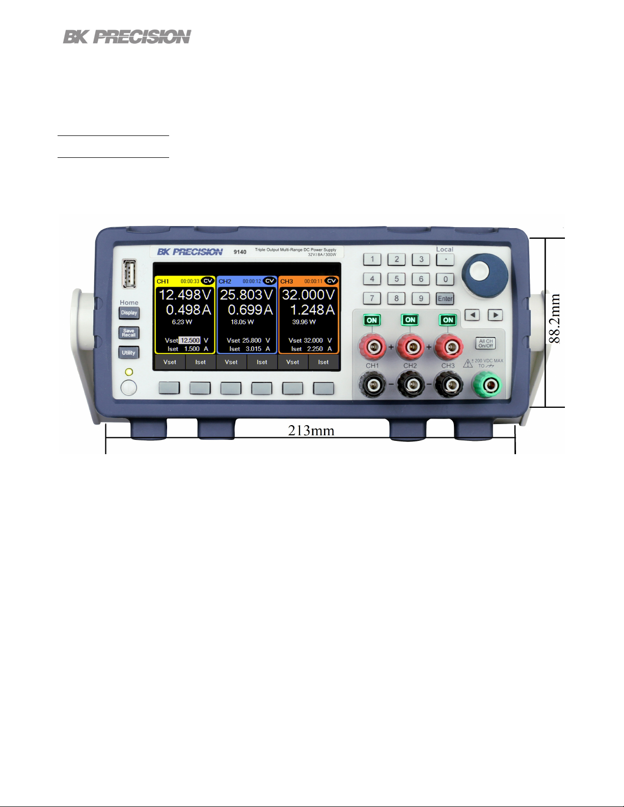
Figure 1.1 Front View
The 9140 Series triple output multi-range DC power supplies combine industry-leading power density
and performance with an extensive set of features in a compact 2U form factor.
Three isolated output channels each produce 100 W of clean power with exceptionally low ripple and
noise characteristics. Combine channels to output up to 300 W, distributing the power across all three
channels. Multiple outputs paired with advanced list mode programming, data logging, and protection
features make these power supplies suitable for a wide range of benchtop or test system applications.
Model 9140 9141
Voltage per Channel 0 to 32 V 0 to 60 V
Current per Channel 0 to 8 A 0 to 4 A
Maximum Power per Channel 100 W
Maximum Combined Power 300 W
Table 1.1 Models
Find Quality Products Online at: sales@GlobalTestSupply.com
www.GlobalTestSupply.com
Page 12

Introduction 12
1.2 Contents
Please inspect the instrument mechanically and electrically upon receiving it. Unpack all items from the
shipping carton, and check for any obvious signs of physical damage that may have occurred during
transportation. Report any damage to the shipping agent immediately. Save the original packing carton
for possible future reshipment. Every power supply is shipped with the following contents:
• 1 x 9140 or 9141 Power Supply
• 1 x AC Power Cord
• 1 x Certicate of Calibration
• 1 x Test Report
Note:
Ensure the presence of all the items above. Contact
the distributor or B&K Precision if anything is missing.
1.3 Features
• Three independent galvanically isolated, oating output channels providing up to 100 W per channel
or 300 W total when combining all three channels
• High power density, compact 2U half-rack form factor
• Multi-ranging operation delivers rated power at various voltage/current combinations
• Combine outputs in parallel or series to increase current or voltage (up to 24 A or 180 V depending
on the model)
• Advanced list mode programming with internal storage for up to 10 list mode programs and list
sequencing capabilities
• Digital I/O block oers external triggering, voltage fault and remote inhibit capabilities
• Overvoltage (OVP), overcurrent (OCP), overtemperature (OTP), and includes a key-lock function
• NISPOM-compliant sanitization procedure to securely erase and return the instrument to factory
settings
Find Quality Products Online at: sales@GlobalTestSupply.com
www.GlobalTestSupply.com
Page 13
Introduction 13
• USB (USBTMC-compliant) and LXI compliant LAN interfaces standard, GPIB optional
• LabVIEW
𝑇 𝑀
, IVI-C, and IVI.NET drivers provided
1.4 Dimensions
The 9140 power supply’s dimensions are approximately:
213 mm (8.4 in) x 88.2 mm (3.47 in) x 330 mm (13 in) (W x H x D).
Figure 1.2 Dimensions
Find Quality Products Online at: sales@GlobalTestSupply.com
www.GlobalTestSupply.com
Page 14

Introduction 14
1.5 Rackmount Installation
The 9140 Series is compatible with the optional 19-inch rackmount kit model RK2US. The RK2US
installation instructions can be downloaded from bkprecision.com
Figure 1.3 Dimensions
Find Quality Products Online at: sales@GlobalTestSupply.com
www.GlobalTestSupply.com
Page 15

1.6 Front Panel
Introduction 15
Figure 1.4 Front Panel
Item Name Description
1 Power Button Power the instrument ON or OFF
2 Function Keys See section ?? for details.
3 USB Host Port USB port used to connect ash drives.
4 Display Visual presentation of the device function and measurements.
5 Numeric Keypad Used to enter precise values.
6 Rotary Knob Used to navigate menues or congure parameters.
7 Output
8 Soft Keys Used to invoke any functions displayed above them.
Isolated and oating output channel supporting sheathed banana
plugs and spade lug type connectors
Table 1.2 Front Panel
Find Quality Products Online at: sales@GlobalTestSupply.com
www.GlobalTestSupply.com
Page 16

1.7 Display
Icon Description
Introduction 16
The output is disabled.
The output is enabled and in constant voltage mode
The output is enabled and in constant current mode
Data loggin is enabled but not recording.
Data logging is enabled and recording.
The instrument is connected to a network.
An issue occured when attempting to connect to a network.
The instrument is not connected to a network.
All keys excluding softkey F6 are locked.
Over voltage protection was triggered.
Over current protection was triggered.
Over temperature protection was triggered.
The instrument is set to remote mode
Remote sense is enabled.
Remote
Table 1.3 Display Icons
Find Quality Products Online at: sales@GlobalTestSupply.com
www.GlobalTestSupply.com
Page 17

1.8 Rear Panel
Introduction 17
Figure 1.5 Rear Panel
Item Name Description
1 Output/Sense
2
3
4 Digital I/O Send or receive a signal to or from an external device.
5 USB interface Connect a USB type B to type A to remotely control the unit.
6 LAN interface
7 Chassis ground
8
Kensington
security slot
GPIB Interface
(Optional)
AC power input
& fuse box
Rear panel output with remote sense. Internal relays switch between
local and remote sensing.
Lock the instrument to a xed location using the security lock via the
lock hole. Lock is not included.
Connect a GPIB cable to remotely control the unit `
Connect a Cat 5/6 Ethernet straight-through patch cable to remotely
control the unit.
Provides a zero potential voltage reference and a dissipation point for
interference, transient voltages and static.
Houses the fuse as well as the AC input.
Table 1.4 Rear Panel
Find Quality Products Online at: sales@GlobalTestSupply.com
www.GlobalTestSupply.com
Page 18

Getting Started
Before connecting and powering up the instrument, please review and go through the instructions in this
chapter.
2.1 Input Power and Fuse Requirements
The supply has a universal AC input that accepts line voltage input within:
9140 9141
AC Line Input 100 - 240 VAC±10%, 47 to 63 Hz
AC Line Phase Single Phase
Maximum Rated
Input Power
Before connecting to an AC outlet or external power source, be sure that the power switch is in the OFF
position and verify that the AC power cord, including the extension line, is compatible with the rated
voltage/current and that there is sucient circuit capacity for the power supply. Once veried, connect
the cable rmly.
The included AC power cord is safety certied for this instrument operating in rated range. To
change a cable or add an extension cable, be sure that it can meet the required power
ratings for this instrument. Any misuse with wrong or unsafe cables will void the warranty.
500 VA
SHOCK HAZARD
The power cord provides a chassis ground through a third conductor. Verify that your
power outlet is of the three-conductor type with the correct pin connected to earth ground.
Find Quality Products Online at: sales@GlobalTestSupply.com
www.GlobalTestSupply.com
Page 19

Getting Started 19
2.2 Fuse Requirements
An AC input fuse is necessary when powering the instrument. The below table shows the fuse required
for all models.
Model Fuse Specication
9140 3.15 AT, 250 V
9141 3.15 AT, 250 V
2.3 Check or Replace Fuse
For safety, no power should be applied to the instrument while changing line voltage
operation. Disconnect all cables connected to the instrument before proceeding.
– Locate the fuse box next to the AC input connector in the rear panel. (See gure 1.5)
– Insert a small athead screwdriver into the fuse box slit to pull and slide out the fuse box as indicated
below.
– Check and replace fuse if necessary. (See gure 2.1)
Figure 2.1 Fuse Removal
Find Quality Products Online at: sales@GlobalTestSupply.com
www.GlobalTestSupply.com
Page 20

Getting Started 20
Any disassembling of the case or changing the fuse not performed by an
authorized service technician will void the warranty of the instrument
SHOCK HAZARD:
Hazardous voltages may exist at the outputs and the load connections when using a power supply
with a rated output greater than 60 V. To protect personnel against accidental contact with hazardous
voltages, ensure that the load and its connections have no accessible live parts. Ensure that the load
wiring insulation rating is greater than to the maximum output voltage of the power supply.
The rear output terminals can accept wire sizes AWG 24 to AWG 12 (See Table 2.1).However, we
recommend using 12 AWG if current output is between 5 to 10 A. Refer to Table 2 below to determine
the proper wire size.
Wire Gauge Rating
AWG 10 12 14 16 18 20 22 24 26 28
Imax (A) 40 25 20 13 10 7 5 3.5 2.5 1.7
mΩ/meter 3.3 5.2 8.3 13.2 21 33.5 52.8 84.3 133.9 212.9
Table 2.1 Wire Gauge Rating
Output Isolation
The output terminals of the 9240 Series are isolated from earth ground. An earth ground terminal is
provided on the front panel for convenience. Any output terminal may be grounded. However, output
terminals must not exceed ±200 VDC.
SHOCK HAZARD:
Floating voltage must not exceed 200 VDC.
Find Quality Products Online at: sales@GlobalTestSupply.com
www.GlobalTestSupply.com
Page 21

2.4 Preliminary Check
Complete the following steps to verify the Power supply is ready for use.
Getting Started 21
Verify AC
Input Voltage
Connect Power
& Self-Test
After Power on, during the self-test, the following should be displayed:
Verify and check to make sure proper AC voltages are available to power the
instrument. The AC voltage range must meet the acceptable specication as
explained in section “2.1 Input Power and Fuse Requirements”.
Connect AC power cord to the AC receptacle in the rear panel and press the
power button. It will run through a self-test procedure initially before booting to
the main screen.
Figure 2.2 Initializing
After the system scan is complete the LCD will display as shown in Figure 2.3
Note:
The initial power on state is based on the settings set on Power-ON
Find Quality Products Online at: sales@GlobalTestSupply.com
www.GlobalTestSupply.com
Page 22
2.5 Self test Errors
Getting Started 22
Figure 2.3 Home Display
The following errors will be displayed if the self-test did not complete successfully:
Error Message Description
EEPROM Fail The internal EEPROM is corrupted or damaged.
System Lost Last system settings within the EEPROM are lost.
Module Fail Channel response failure.
Cal Lost Calibration data within the EEPROM is lost.
Fact Loss Factory calibration data is lost.
Model Lost Channel initialization failed.
Table 2.2 Error Message
If any of these errors occur, please contact B&K Precision.
Find Quality Products Online at: sales@GlobalTestSupply.com
www.GlobalTestSupply.com
Page 23

Basic Front Panel Operation
At power-on, the power supply will automatically enter the front-panel operation mode and the instrument
can be controlled via the front panel keys and knob.
3.1 Keys
3.1.1 Main Keys
There are three main keys:
Navigates the 5 available screens.
When navigating any menu
returns the key will return "Home"
main display
5 available displays:
– Main page:
Overview of the 3 outputs.
– Single Channel Display 1 to
3: Detailed channel overview.
– Live Output Monitoring:
Oscilloscope like overview
of the measured output
parameters.
More information on each display in 3.2.
Opens up a menu giving access
to various save and load options,
regardless of the current display
of the screen.
Opens the main menu bar. If
a menu bar is already open,
pressing will navigate to
the main menu bar.
Find Quality Products Online at: sales@GlobalTestSupply.com
www.GlobalTestSupply.com
Page 24

Basic Front Panel Operation 24
3.1.2 Soft Keys
The unit has six soft keys, which are located beneath the screen. Each key selects the corresponding
function. Functions will vary depending on the current menu or display.
Figure 3.1 Soft Keys
3.1.3 Numeric Keys
The numeric keys allow the conguration of various parameters. Using the numeric keys provides a fast
and precise input. The key can be found with the numeric keys. Pressing enter will assign the
selected value to the desired parameter.
Figure 3.2 Numeric Keys
3.1.4 Output Control
The button toggles the output On/O. When output is enabled, the ON button will turn green
and the supply will display the state of the channel.
represents constant current mode. represents constant voltage mode. This is indicated for
each channel independently. When output is disabled, the channel state will display .
The key toggles all the channels On/O simultaneously. Its function may vary depending on the
coupling state of the channels. For more information go to Coupling.
Find Quality Products Online at: sales@GlobalTestSupply.com
www.GlobalTestSupply.com
Page 25

Basic Front Panel Operation 25
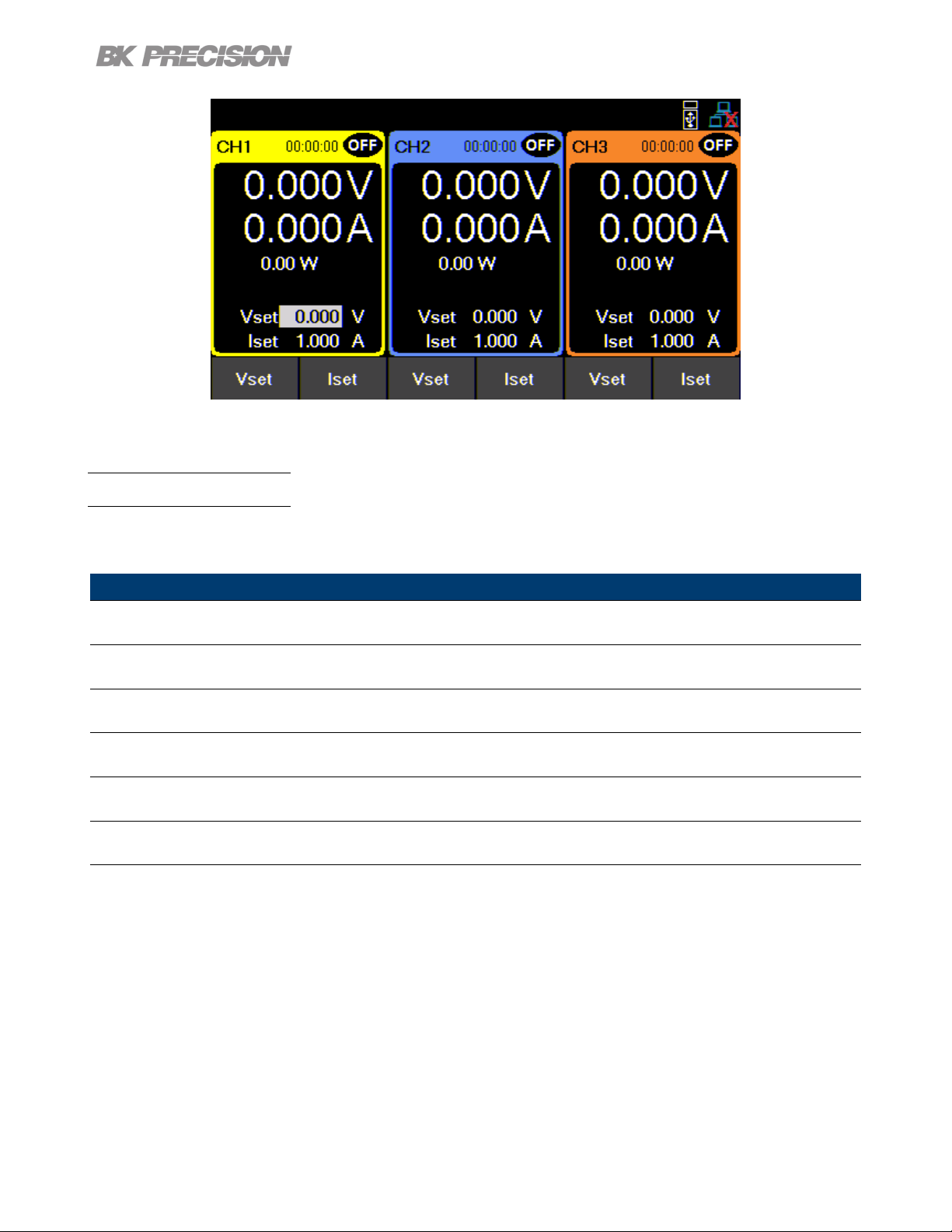
3.2 Display
These power supplies have three main display modes: three channel display, single channel display, and
live output monitoring display. Press the button to cycle between the dierent display modes or to
return home when viewing any other menu.
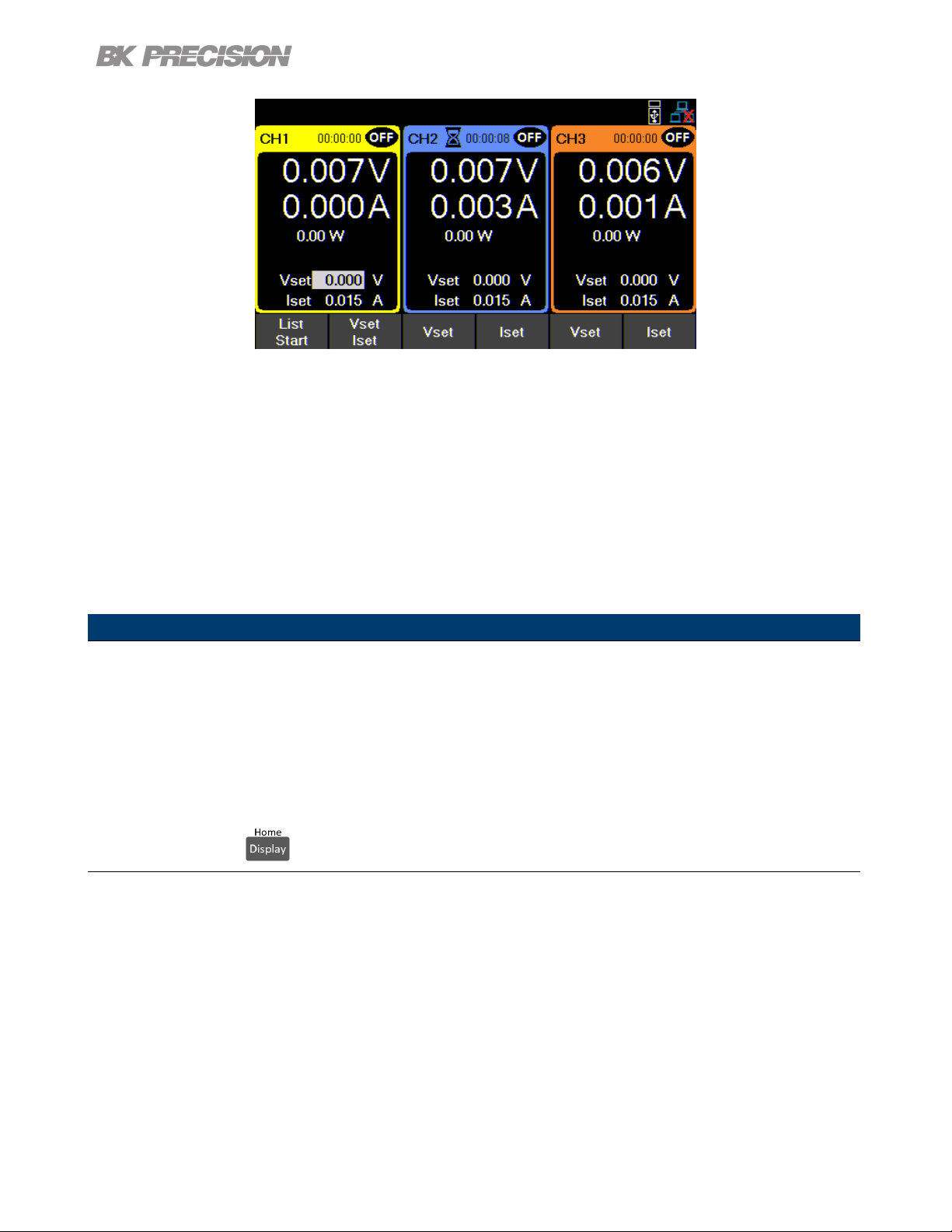
Three Channel Display
Provides information of the outputs’:
• State
• Run time
• Voltage
• Current
• Power
Allows conguration of:
• Vset
• Iset
Figure 3.3 Three Channel Display
Find Quality Products Online at: sales@GlobalTestSupply.com
www.GlobalTestSupply.com
Page 26
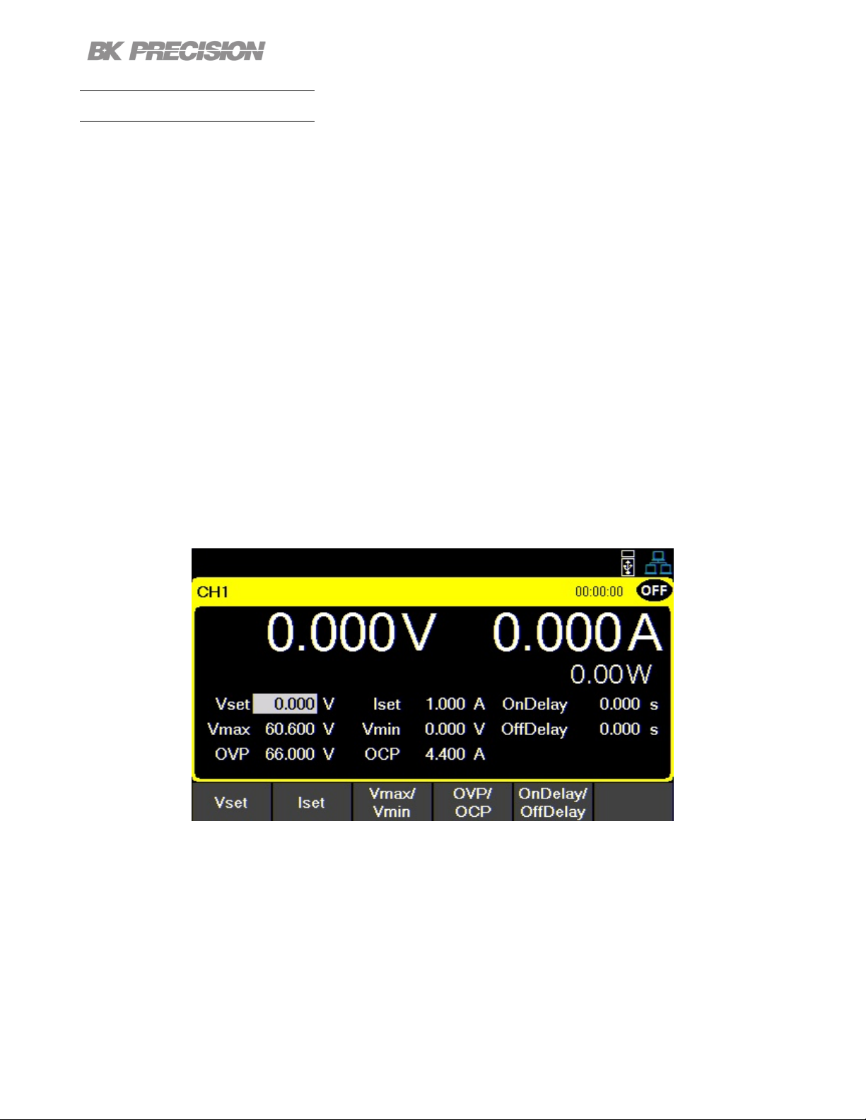
Single Channel Display
Basic Front Panel Operation 26
Provides information of the outputs’:
• State
• Run time
• Voltage
• Current
• Power
• Vmax/Vmin
• OVP/OCP
• OnDelay/ODelay
Allows conguration of:
• Vset
• Iset
• Vmax/Vmin
• OVP/OCP
• OnDelay/ODelay
Figure 3.4 Single Channel Display
Find Quality Products Online at: sales@GlobalTestSupply.com
www.GlobalTestSupply.com
Page 27

Basic Front Panel Operation 27
Live Output Monitoring
The live output monitoring display shows metered output voltage and current over time.
It is always active and will continuously plot and overwrite the oldest value when the display graph is full.
Figure 3.5 Live Output Monitoring Display
The Live output display can be congured by setting the: Voltage, Current, and Time Scale.
Voltage Scale
The voltage scale of each output can be set from 10 mV/Div up to 20 V/Div.
1. While in Live Output Display use the softkeys to select Voltage Scale.
2. Select a channel to congure.
3. Use the rotary knob to navigate through the available scales.
Current Scale
The current scale of each output can be set from 10 mA/Div up to 3 A/Div.
1. While in Live Output Display use the softkeys to select Current Scale.
2. Select a channel to congure.
3. Use the rotary knob to navigate through the available scales.
Find Quality Products Online at: sales@GlobalTestSupply.com
www.GlobalTestSupply.com
Page 28

Basic Front Panel Operation 28
Time Scale
The time scale of each output can be set from 1 s/Div up to 10 min/Div.
1. While in Live Output Display use the softkeys to select Time Scale.
2. Use the rotary knob to navigate through the available scales.
Voltage Oset
A voltage oset can be added to each output. The oset can be set from 0 V up to 60.6 V on the 9141
and 0 V up to 32.2 V on the 9140.
1. While in Live Output Display use the softkeys to select Voltage Oset.
2. Select a channel to congure.
3. Use the rotary knob to navigate through the available scales.
Current Oset
A current oset can be added to each output. The oset can be set from 0 A up to 4.4 A on the 9141
and 0 A up to 8.8 A on the 9140.
1. While in Live Output Display use the softkeys to select Current Oset.
2. Select a channel to congure.
3. Use the rotary knob to navigate through the available scales.
3.3 Check Model and Firmware Version
The rmware version, model, and serial number can be veried by entering the security settings. Press
button then use the soft keys to select Utilities > Help > System Info to view model and rmware
information.
Find Quality Products Online at: sales@GlobalTestSupply.com
www.GlobalTestSupply.com
Page 29

Basic Front Panel Operation 29
3.4 Setting Voltage and Current
Follow the steps below to set the output voltage or current. The values can be entered using the numeric
keypad or the rotary knob.
1. Using the keypad: Use the soft keys to select the channel VSET or ISET settings beneath channel
view on the display. Then use the numeric keypad to input the voltage or current value then press
to conrm.
2. Using the rotary knob: Use the soft keys to select the channel VSET or ISET settings beneath
the channel view on display. Then turn the knob clockwise to increment or counter-clockwise to
decrement the value.
a. Use the below the rotary knob to move the cursor. Press the knob in to conrm.
Find Quality Products Online at: sales@GlobalTestSupply.com
www.GlobalTestSupply.com
Page 30
Output Conguration
4.1 Protection Settings
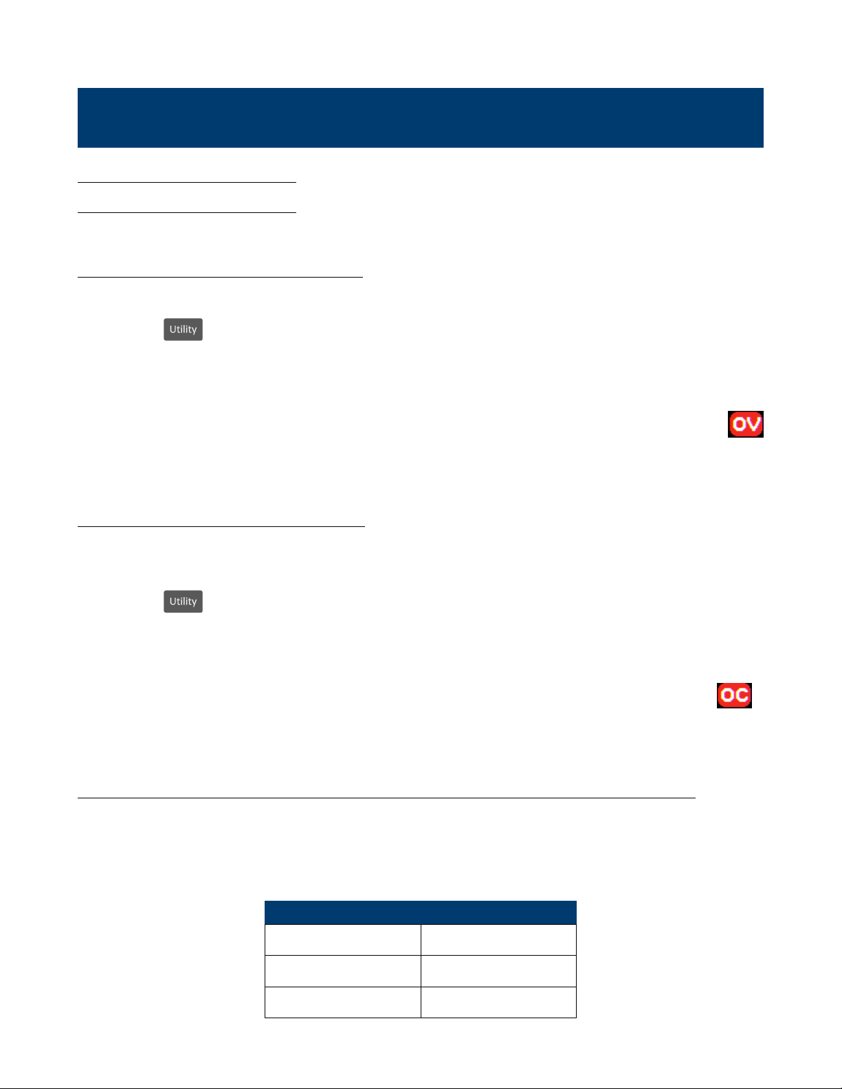
4.1.1 Over Voltage Protection (OVP)
Over voltage protection is always enabled, however the user can set the OVP voltage limits.
1. Press the button then use the soft keys to select Output cong > Protection settings
2. Use the soft keys to select a channel to adjust.
3. Select OVP Limit.
4. Use the numeric keypad or rotary knob to set the desired OVP limit.
When OVP protection is tripped during operation, the output will be de-rated to 0 V and the icon
will appear between the wattage and Vset.
4.1.2 Over Current Protection (OCP)
Over current protection state and limit can be set in the protection settings.
1. Press the button then use the soft keys to select Output cong > Protection settings
2. Use the soft keys to select a channel to adjust.
3. Press OCP State to toggle the over current protection on or o.
4. Select OCP Limit and use the numeric keypad or rotary knob to set limit value.
When OCP protection is tripped during operation, the output will be de-rated to 0 V and the icon
will appear between the wattage and Vset.
4.1.3 Over Temperature Protection & Over Temperature Warning (OTP & OTW)
The state and limit of both OTP & OTW cannot be set or congured in the protection settings. OTP is set
to 85 °C and OTW is set to 75 °C. If the temperature reaches either OTW, the OT icon will blink on the
display with a low period beep sound. If temperature reaches OTP the OT icon will show on the display
and the output will turn o. The output will not be allowed to turn on until the temperature drops to 75 °C.
Fan Speed Control
2 A 0%
2 to 5 A 25%
5 A 100%
Find Quality Products Online at: sales@GlobalTestSupply.com
www.GlobalTestSupply.com
Page 31

Output Conguration 31
4.1.4 Vmax/Vmin
Congure the maximum or minimum voltage value the user can set from the protection
settings.
1. Press the button then use the soft keys to select Output cong >
Protection settings
2. Use the soft keys to select a channel to adjust.
3. Select Vmax or Vmin and set a maximum or minimum value using the numeric keypad or rotary knob.
4.1.5 Protection Clear
Protections are cleared from the output conguration settings as shown in the following steps.
1. Press the button then use the soft key to select Output cong >
Protection Clear.
2. Press the soft key to clear the protection for the corresponding channel, or select
All CH Clear to clear protections on all three channels.
4.2 Output Settings
4.2.1 Remote Sense
Remote sense can be used to compensate for voltage drops (up to 1 V) due to resistance from test leads
connected to your device under test (DUT), thus providing more accurate output voltage. When remote
sense is enabled, the positive (+S) and positive lead (+) of the DC output are connected to the positive
(+) of the load. Similarly, the negative sense (-S) and negative lead (-) of the DC output are connected
to the negative (-) end of the load shown in gure 4.1
Figure 4.1 Remote Sense
Find Quality Products Online at: sales@GlobalTestSupply.com
www.GlobalTestSupply.com
Page 32

Output Conguration 32
Never connect any power source into any of the terminals at any time during operation.
When output is enabled, DO NOT use your hands to touch the terminals or the screws that are
designed to tighten wires to the terminals. Doing so may create a shock hazard under high
voltage output conditions.
DO NOT at any time disconnect the wires from the S+ and S- terminals to the DUT while output
is enabled (ON). Doing so may damage the power supply and cause unstable output.
Remote sense is disabled by default, see the following steps to enable remote sense:
1. Press the button then use the soft key to select Output cong > Output Settings.
2. Select a desired channel to congure.
3. Press Remote Sense using the soft key to enable remote sense.
4.2.2 Output Timer
Output timer can be set for each channel individually. When the output timer is enabled, an hourglass
icon will be displayed next to the channel number. The timer countdown will begin when the channel
output is enabled. The output is disabled when the countdown reaches 0. The timer can be set from 1
second to 99 hours 59 minutes and 59 seconds.
Follow the steps below to enable and set the output timer:
1. Press the button then use the soft key to select Output cong > Output Settings.
2. Select a desired channel to congure. Push Timer State to enable the timer.
3. Select Timer Setting and set a desired time for the output to be enabled using the numeric keypad or
rotary knob. The timer format is: HH:MM:SS. Use the keys to move the cursor.
Find Quality Products Online at: sales@GlobalTestSupply.com
www.GlobalTestSupply.com
Page 33
Output Conguration 33
4.2.3 Voltage Slew
The rising voltage slew rate can be set in volts per second. The voltage slew range can be set from
0.001 V/s to 3200.0 V/s.
1. Press the button then use the soft key to select Output cong > Output Settings.
2. Select a desired channel to congure.
3. Select Voltage Slew and use the numeric keypad or rotary knob to adjust the slew rate value. Press
to conrm input.
4.2.4 Current Slew
The rising current slew rate can be set in amps per second. The current slew range can be set from
1 A/s to 800 A/s.
1. Press the button then use the soft key to select Output cong > Output Settings.
2. Select a desired channel to congure.
3. Select Next Pg. > Current Slew and use the numeric keypad or rotary knob to adjust the slew rate
value. Press to conrm input.
4.2.5 On/O Delay
A channel on or o delay in seconds can be applied to any channel. These delays can be set from
0.001 s to 3600.0 s.
1. Press the button then use the soft key to select Output cong > Output Settings.
2. Select a desired channel to congure.
3. Select Next Pg. > On Delay to set an on delay or O Delay to set an o delay.
4. Use the numeric keypad or rotary knob to adjust the delay value. Press to conrm input.
Find Quality Products Online at: sales@GlobalTestSupply.com
www.GlobalTestSupply.com
Page 34

Output Conguration 34
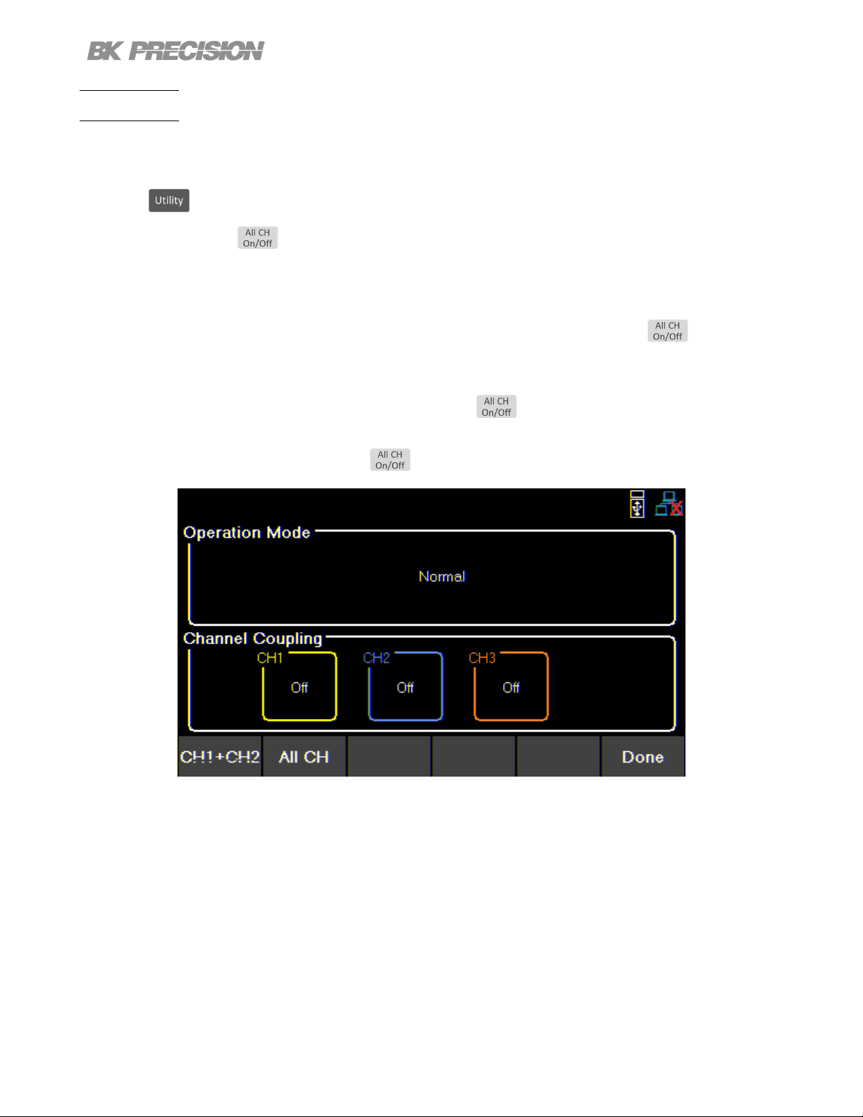
4.3 Operating Mode and Coupling
Set the operation mode or coupling.
Press the button then use the soft key to select Output Cong > Op. Mode/Coupling > Operation
Mode.
4.3.1 Normal Mode
Sets operation mode to Normal.
Normal mode sets the instrument to operate as a true triple output power supply.
Press the button then use the soft key to select Output Cong > Op. Mode/Coupling >
Operation Mode > Normal.
9140 9141
Individual CH Individual CH
32 V 8 A 60 V 4 A
Figure 4.2 Normal Mode
Find Quality Products Online at: sales@GlobalTestSupply.com
www.GlobalTestSupply.com
Page 35

In Normal mode the main page will display the three outputs.
Toggles through CH1, CH2, CH3, and live output monitoring display.
Output Conguration 35
Figure 4.3 Normal Mode Main Page
Single CH displays more information about the output, and allows conguration of more parameters.
Figure 4.4 Single Channel
Find Quality Products Online at: sales@GlobalTestSupply.com
www.GlobalTestSupply.com
Page 36

Output Conguration 36
4.3.2 Series Mode
Set operation mode to Series.
Series mode changes the UI to accurately represent the possible outputs congurations.
Series mode does not internally wire the outputs. The outputs must be connected externally to increase
the available voltage range.
Press the button then use the soft key to select Output Cong > Op. Mode/Coupling > Operation
Mode > Series.
The image below illustrates the external wiring required to connect all channels in series. If CH1+ CH2
is chosen CH2’s positive terminal does not connect to CH3’s negative terminal.
Series CH1+2 Series All
9140 9141
CH1 + CH2 All CHs CH1 + CH2 All CHs
64 V 96 V 120 V 180 V
Find Quality Products Online at: sales@GlobalTestSupply.com
www.GlobalTestSupply.com
Page 37
Output Conguration 37
CH1 + CH2
Operation mode will be set to Series 1 + 2. Changing operation mode will undo previous coupling
conguration.
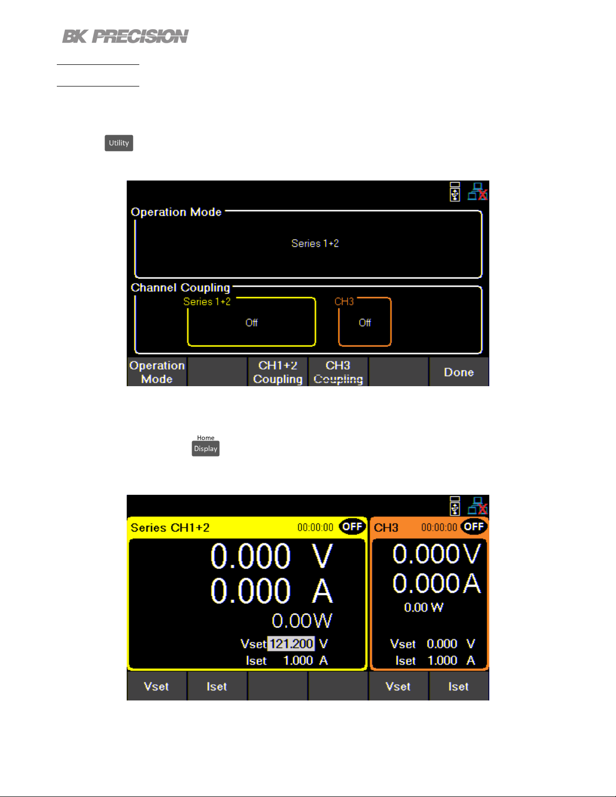
Press the button then use the soft key to select Output Cong > Op. Mode/Coupling > Operation
Mode > Series > CH1 + CH2.
Figure 4.5 Series 1+2
In Series CH1 + 2 the main page will display the output of the combined outputs, as well as the output
of the individual CH3. The button will toggle through single channel display for Series CH1 + 2,
CH 3, and live output monitoring.
Figure 4.6 Series CH1+2 Main Page
Find Quality Products Online at: sales@GlobalTestSupply.com
www.GlobalTestSupply.com
Page 38

Output Conguration 38
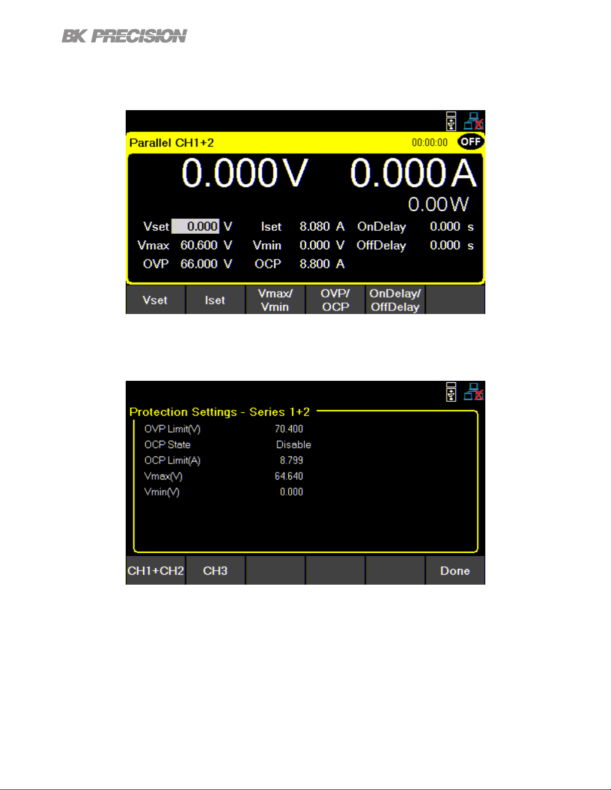
Single CH displays more information about the output, and allows conguration of more parameters.
The voltage congurations will now range from 0 v to 64 V for model 9140 and 0 V to 120 V for model
9141.
Figure 4.7 Series CH1+2 Single Channel Display
Protection Setting menu will also adjust the congurable values.
Figure 4.8 Series CH1+2 Protection Settings
Find Quality Products Online at: sales@GlobalTestSupply.com
www.GlobalTestSupply.com
Page 39

Output Conguration 39
Series All
Operation mode will be set to Series All. Coupling will not be available in Series All mode.
Press the button then use the soft key to select Output Cong > Op. Mode/Coupling > Operation
Mode > Series > Series All.
Figure 4.9 Series All
In Series All mode will only toggle between the Series All display and live output monitoring.
Series All CH display will adjust to voltage conguration between 0 V and 96 V for model 9140 and 0 V
to 180 V for model 9141.
Figure 4.10 Series All Main Page
Protection Setting menu will also adjust the congurable values.
Find Quality Products Online at: sales@GlobalTestSupply.com
www.GlobalTestSupply.com
Page 40
Output Conguration 40
Parallel Mode
Set operation mode to Parallel.
Parallel Mode does not internally wire the outputs. The outputs must be connected externally to increase
the available current range.
Parallel Mode changes the UI to accurately represent the possible output congurations.
Press the button then use the soft key to select Output Cong > Op. Mode/Coupling > Operation
Mode > Parallel.
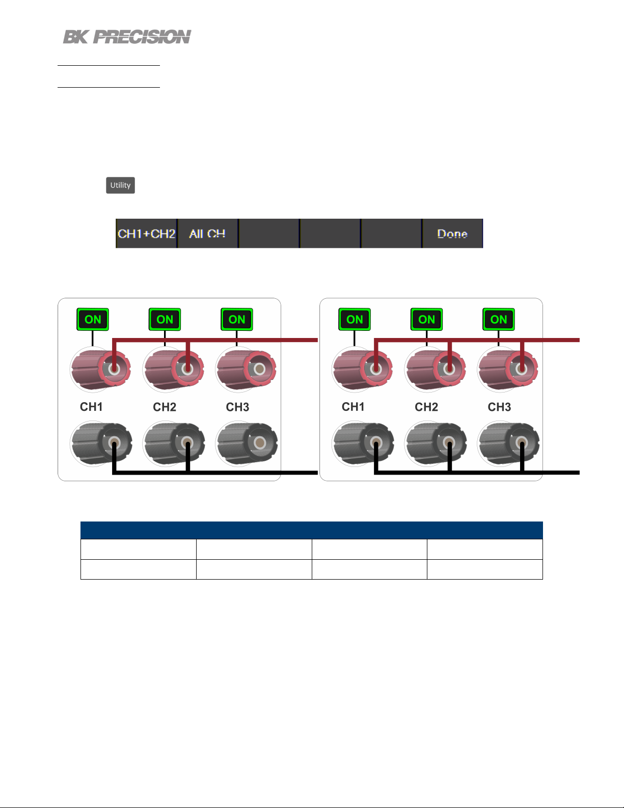
The image below illustrates the external wiring required to connect all channels in Parallel. If CH1+ CH2
is chosen CH2’s terminals do not connect to CH3’s terminals.
Parallel CH1+2
Parallel All
9140 9141
CH1 + CH2 All CHs CH1 + CH2 All CHs
16 A 24 A 8 A 12 A
Table 4.1 Parallel Mode
Find Quality Products Online at: sales@GlobalTestSupply.com
www.GlobalTestSupply.com
Page 41

Output Conguration 41
CH1 + CH2
Operation mode will be set to Parallel 1 + 2. Selecting an operation mode will undo previous coupling
conguration.
Press the button then use the soft key to select Output Cong > Op. Mode/Coupling > Operation
Mode > Parallel > CH1 + CH2.
Figure 4.11 Parallel CH 1+2
In Parallel CH1 + 2 Mode the main page will display the output of the combined outputs, as well as the
output of the individual CH3. The button will toggle through single channel display for Parallel CH1
+ 2, CH 3, and live output monitoring.
Figure 4.12 Parallel CH 1+2 Main Display 9141
Find Quality Products Online at: sales@GlobalTestSupply.com
www.GlobalTestSupply.com
Page 42
Output Conguration 42
The Single CH display will adjust to allow current conguration between .030 A to 16 A for model 9140
and .030 A to 8 A for model 9141.
Figure 4.13 Parallel CH 1+2 Single Channel Display
Protection Setting menu will also adjust the congurable range of each parameter.
Figure 4.14 Parallel CH 1+2 Protection Settings
Find Quality Products Online at: sales@GlobalTestSupply.com
www.GlobalTestSupply.com
Page 43

Output Conguration 43
Parallel All
Operation mode will be updated based on selected mode. Coupling is not available.
Figure 4.15 Parallel All Operation Mode
In Parallel All Mode the button will only toggle between the Parallel All display and live output
monitoring.
Parallel All CH display will adjust to allow value conguration of .045 to 24 A for model 9140 and .045 A
to 12 A for model 9141.
Figure 4.16 Parallel All Main Page
Protection Setting menu will also adjust the congurable values.
Find Quality Products Online at: sales@GlobalTestSupply.com
www.GlobalTestSupply.com
Page 44

Tracking
Output Conguration 44
Figure 4.17 Parallel All Main Page
Voltage levels are tracked on either CH1+2 or All Channels.
Press the button then use the soft key to select Output Cong > Op. Mode/Coupling >
Operation Mode > Tracking.
Tracking mode allows real time voltage tracking across all channels or between CH1 and CH2.
When tracking mode is enabled, list mode will still operate independently on the channel that has list
enabled. Tracking channels will not track the list changes.
Figure 4.18 Tracking Mode
Find Quality Products Online at: sales@GlobalTestSupply.com
www.GlobalTestSupply.com
Page 45
Output Conguration 45
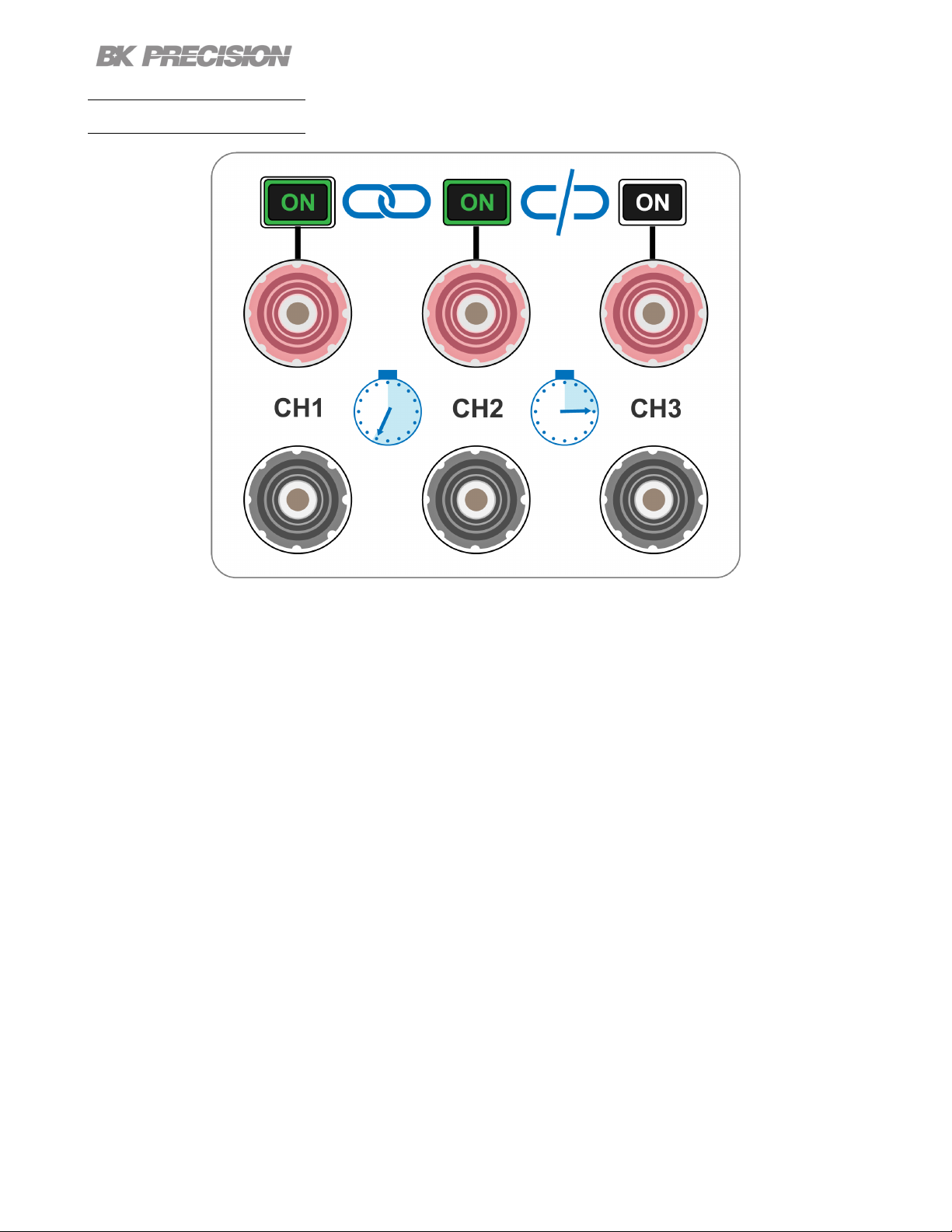
Coupling
Enable or disable the output coupling between multiple output channels, by using the soft keys to toggle
individual channel coupling On or O.
Press the button then use the soft key to select Output Cong > Op. Mode/Coupling
If coupling is enabled, will follow the coupling settings. Channel output On/O buttons will also
follow the coupling settings if the correlated channel is coupled to another channel.
Example:
If CH1 and CH2 are coupled and the coupled CHs are on, will not turn on
CH3. It will turn o CH1 and CH2.
However, if all channels are OFF will turn all CHs ON.
If all CHs are ON will turn all CHs OFF.
Figure 4.19 Parallel All Main Page
Find Quality Products Online at: sales@GlobalTestSupply.com
www.GlobalTestSupply.com
Page 46
Output Sequencing
Output Conguration 46
Figure 4.20 Sequencing
Combine CH Coupling with Output On and O Delay to toggle the outputs in a set sequence.
To congure a sequence:
1. Set voltage and current output of the participating channels.
Reference section Setting Voltage and Current.
2. Synchronize output state by coupling of all participating channels.
Reference section Coupling
3. Congure the turn on order of the outputs using the On and O Delay.
Reference section Output Timer
Begin the sequence by turning on any of the participating outputs.
Find Quality Products Online at: sales@GlobalTestSupply.com
www.GlobalTestSupply.com
Page 47
List Mode
The 9140 and 9141 are capable of storing up to 10 programmable lists in the internal memory. Each list
can have up to 100 congurable steps.
List memory is shareable across all 3 channels, allowing the channels to run the same list or dierent list
simultaneously.
If all ten list numbers are taken, a list can also be saved to a USB. Lists can be loaded from a USB,
allowing for a larger collection of programmed lists.
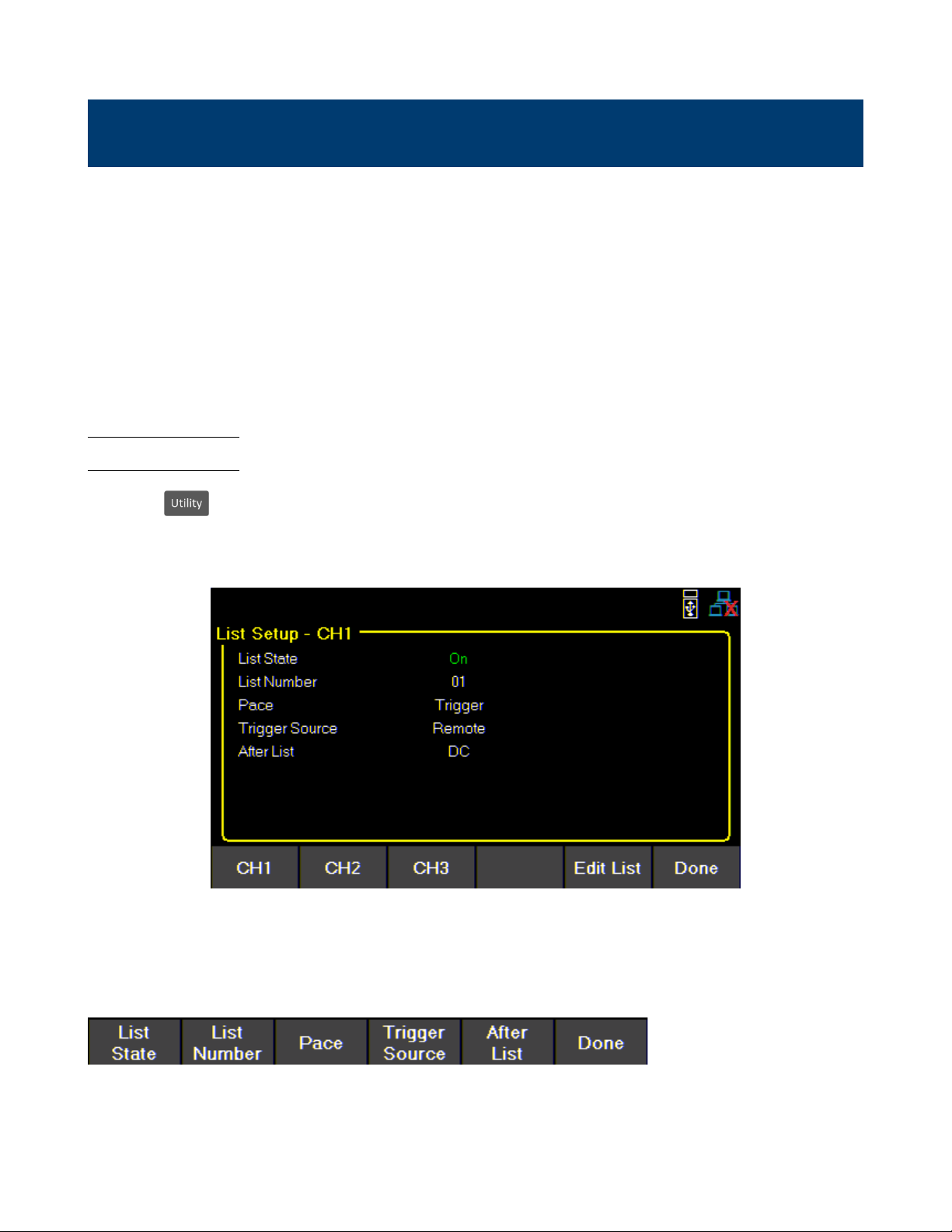
5.1 List Setup
Press the button then use the soft key to select List Setup.
Use the softkeys to select one of the channels CH1, CH2, or CH3.
Figure 5.1 List Setup
Use the softkeys to set the following parameters.
Find Quality Products Online at: sales@GlobalTestSupply.com
www.GlobalTestSupply.com
Page 48

List State:
Toggle list state On/O for the selected channel.
List Number:
Select a list program from the memory to run on the channel.
Use the numeric keypad or rotary knob to select list number.
Press to assign the list to a channel.
Pace:
Set the pace in which steps are executed.
a. Dwell: The next step outputs once the dwell time elapsed.
List Mode 48
b. Trigger: After the dwell time elapsed, wait for a trigger before outputting the next step.
Trigger Source
Set the trigger source.
a. Manual: Select to use a manual trigger. The Trigger softkeywill be availableonce List State is on and
exit out of the menu to the main display.Press it to manually trigger the list program. If the step dwell
time has not elapsed, then Trigger will not have a white background. When dwell timeelapses, Trigger background
color will turn white to indicate the trigger is ready.
Figure 5.2 Waiting for Trigger
Find Quality Products Online at: sales@GlobalTestSupply.com
www.GlobalTestSupply.com
Page 49

List Mode 49
b. Digital IO: Select to use the digital I/O pins to receive a trigger. To assign trigger input function to a
pin see 7.4.1.
c. Remote: Select to receive a trigger from the remote interface.
After List
Sets the voltage and current settings at the end of the list program.
a. DC: Returns to the last DC output voltage and current setting prior to enabling list mode.
b. Last: Retains the last step voltage and current setting after the list program ends.
Note:
If the list is aborted, the output will return to the last set voltage and current
output values before the list began, even if After List is set to Last.
5.2 Edit List
Press the button then use the soft key to select List Setup > Edit List.
Use the softkeys to set the following parameters.
Find Quality Products Online at: sales@GlobalTestSupply.com
www.GlobalTestSupply.com
Page 50
List Mode 50
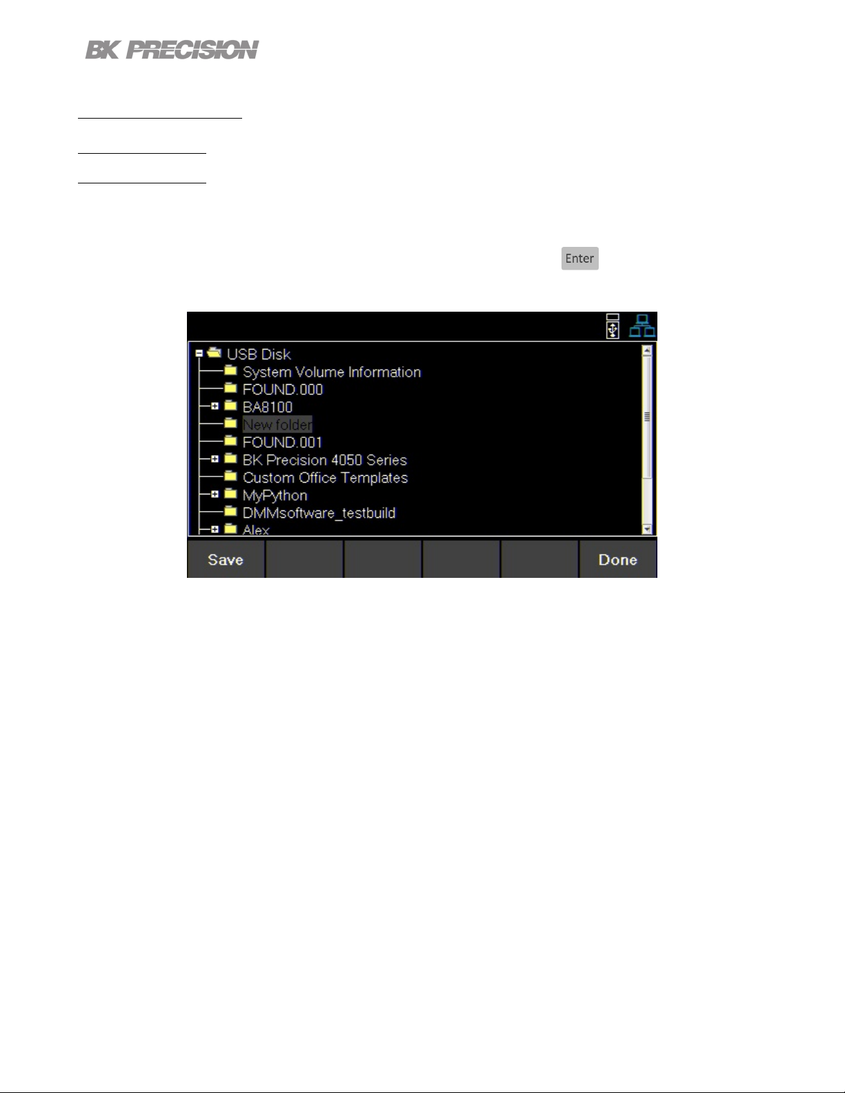
5.2.1 Load/Save List
Save to USB
Save the selected list program to a USB.
Use the rotary knob to navigate through the le paths of the USB. Use the button to expand folders.
Once the desired location has been found select Save by pressing the softkey furthest to the left.
Figure 5.3 Save to USB
Find Quality Products Online at: sales@GlobalTestSupply.com
www.GlobalTestSupply.com
Page 51

List Mode 51
Load from USB
Load a previously saved list from a USB to selected List Number.
Use the rotary knob to navigate through the le paths of the USB. Use the button to expand folders.
Once the desired location has been found select Load by pressing the softkey furthest to the left.
Figure 5.4 Load from USB
Note:
The list must be saved/overwritten at the selected list number location before it is able to be assigned.
5.2.1 List Number
1. Select a list program from the internal memory.
2. Use the numeric keypad or rotary knob to select a list (0 to 9).
3. Press
Find Quality Products Online at: sales@GlobalTestSupply.com
www.GlobalTestSupply.com
Page 52

List Mode 52
5.2.2 Next
Set the next list program to run after the current list elapse.
a. To make a list run continuously and indenitely, set Next to the same number as List Number.
b. To run dierent list sequences continuously, set Next to each other.
Example Set Next on List 1 to 2.
Set Next on List 2 to 1.
5.2.3 Repeat
To repeat a list, set Repeat using the numeric keypad or rotary knob and press .
5.2.4 Steps
Add, delete, clear all, or edit steps.
Add Step
Use the softkeys to add a step to the list. The step added will be a duplication of the step selected before
pressing Add Step.
To select a step to duplicate, use the rotary knob to navigate the available steps. If the list is new, only
one default step will be available. Pressing Add Step will duplicate the default step.
Figure 5.5 Default Step In New List
Find Quality Products Online at: sales@GlobalTestSupply.com
www.GlobalTestSupply.com
Page 53

Delete Step
Delete the step selected before pressing Delete Step.
Use the rotary knob to navigate between each step.
Clear All
Clear all list parameters. See g 5.5
Edit Step
Use the rotary knob to navigate the steps available.(select a row)
To edit parameters of the step, use the keys.(selects a column)
See gure 5.6 for the parameter each row edits.
List Mode 53
Press to toggle enable/disable BOST and/or EOST.
Figure 5.6 List Conguration
Find Quality Products Online at: sales@GlobalTestSupply.com
www.GlobalTestSupply.com
Page 54

Voltage Sets Vset value.
When setting Vset the list will not limit the voltage range based on mode.
Therefore, Vmax will be 96.960 for model 9140 and 180.800 for model 9141.
To prevent a protection trip, verify the Vset and Iset values in the list is within
the range of the congured operation mode before running the list.
Current Sets Iset value.
When setting Iset the list will not limit the current range based on mode.
Therefore, Imax will be 24.240 for model 9140 and 12.120 for the 9141.
To prevent a protection trip, verify the Vset and Iset values in the list is within
the range of the congured operation mode before running the list.
List Mode 54
Step Parameters
BOST Press the knob or to enable/disable a trigger-out signal at the beginning of the step (BOST).
EOST Press the knob or to enable/disable a trigger-out signal at the beginning of the step (EOST).
Dwell Sets the dwell time of the selected step.
Find Quality Products Online at: sales@GlobalTestSupply.com
www.GlobalTestSupply.com
Page 55

List Mode 55
5.3 List Run
List allows a sequence of outputs with up to 100 congurable steps. With sharable memory across all
three channels, a list can run simultaneously on various channels. This allows for a list to be compatible
in normal, parallel or series mode.
Before running a list its parameters must be congured.
1. Congure the parameters of each step. See 5.2
2. Set the settings of the channel which will output the list. See 5.1
a. Enable List State on desired channel.
b. Assign a List Number to the channel.
c. Select Pace {Dwell or Trigger}.
d. Select Trigger Source {Manual, Digital IO, or Remote }.
e. Select After List output {DC or Last}.
3. After conguring the list and channel parameters press to return to the main page.
– Vset will be replaced with List Start if List State was enabled.
Figure 5.7 List State Disabled
4. Select List start to start the list.
– Once the list begins List Start will change to Abort List
Find Quality Products Online at: sales@GlobalTestSupply.com
www.GlobalTestSupply.com
Page 56
List Mode 56
Figure 5.8 List State Enabled CH 1
– The interaction with the list will vary depending on the chosen Pace. See 5.1
5. Select List Abort to end the list before all steps elapse. If the all steps elapse the list will end and the
output will be set to chosen After List parameter.
– If After List is set to DC the output will output the Vset and Iset values.
– If After List is set to Last the output will output the values of the last step in the list.
Note:
While the list is running the user can adjust the current step output by setting Vset or Iset on the main
display. Doing so will immediately change the value of the ongoing output. However, the set value will
not be saved to the list. Once the dwell time of the step has elapsed the list will continue and output
the next step.
If Trigger source is set to manual, Vset/Iset will not be available. The rotary knob and numeric keypad
can be used to adjust the selected value. To adjust both Vset/Iset navigate to the single CH display of
the output using the key.Vset/Iset will be available as shown in gure 5.9.
Find Quality Products Online at: sales@GlobalTestSupply.com
www.GlobalTestSupply.com
Page 57

Figure 5.9 Single Channel Display Vset/Iset
List Mode 57
Find Quality Products Online at: sales@GlobalTestSupply.com
www.GlobalTestSupply.com
Page 58

Data Logger
The data logger can record the output voltage, current, and error codes of all three channels. Log data
can be congured to record either Voltage only, Current only, or both.
Connect a USB ash drive to the front panel USB port. Max. Recording time will vary based on the ash
drive size and the amount of the data being logged.
Figure 6.1 Data Logger Max Time
6.1 Using the Data Logger Function
Press the button then use the soft key to select Data logger. The Data Logger settings can be
selected in this menu.
Before starting the Data Logger its settings must be adjusted.
1. Set the desired Sampling Interval See 6.2.1
2. Select a File Path to determine where to store the collected data. see 6.2.2
3. Enable or disable T. Stamp Filename. See 6.2.3
4. Choose what data to record. See 6.2.4
5. Enable or disable Status Code. See 6.2.5
6. Select a Trigger Source. See 6.2.6
7. After setting all desired parameters press datalog Start/Stop to begin recording. Staring data log
will vary based on chosen trigger. See6.2.7
Find Quality Products Online at: sales@GlobalTestSupply.com
www.GlobalTestSupply.com
Page 59

Data Logger 59
6.2 Parameters
6.2.1 Sampling Interval
Press the button then use the soft key to select Data logger > Sampling Interval.
Use the numeric keypad or rotary motor to select the sampling interval. Press to assign the selected
value. (.2s to 300s)
6.2.2 File Path
Press the button then use the soft key to select Data logger > File Path.
Using the rotary knob and navigate through the le path of the USB. Once the desired location
has been found select save by pressing the softkey furthest to the left.
Verify that the correct path was chosen in the Data Logger menu.
Figure 6.2 File Path Selected
6.2.3 T. Stamp Filename
Press the button then use the soft key to select Data logger > T. Stamp Filename
Toggle to enable/disable time and date on the le name.
Example Enabled 9140_log_20201017002307
Disabled 9140_log
Find Quality Products Online at: sales@GlobalTestSupply.com
www.GlobalTestSupply.com
Page 60
Data Logger 60
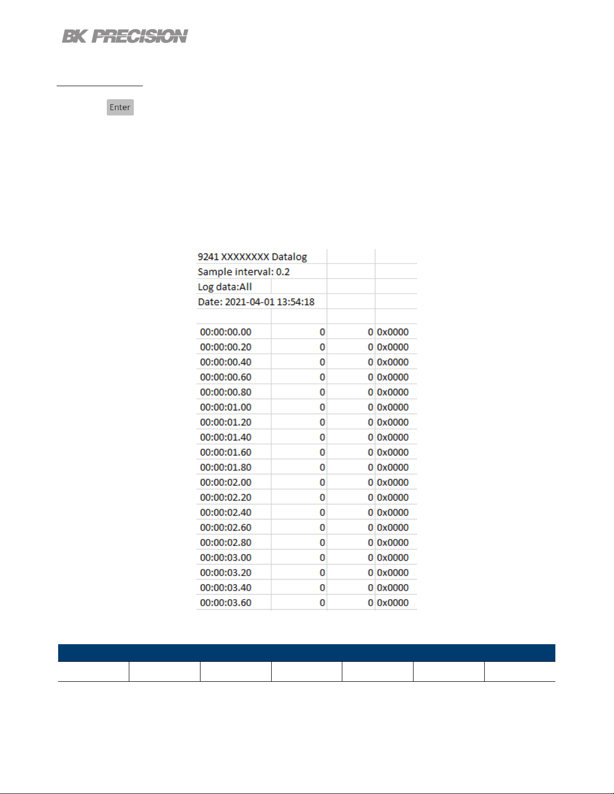
6.2.4 Log Data
Press the button then use the soft key to select Data logger > Next Pg. > Log Data.
Select data to be logged.
– All: Record both voltage and current output of all channels.
– Voltage: Record the voltage output of all channels.
– Current: Record the current output of all channels.
Figure 6.3 Log Data All
The data is recorded in the following order:
CH1 Voltage CH1 Current CH2 Voltage CH2 Current CH3 Voltage CH3 Current Status Code
Table 6.1 Data Order
Find Quality Products Online at: sales@GlobalTestSupply.com
www.GlobalTestSupply.com
Page 61
Note:
Data order will vary depending on Log Data selected.
6.2.5 Status Code
Press the button then use the soft key to select Data logger > Status Code.
Toggle to enable/disable status code.
Enabled Status Code will record all codes reported. See 6.3 for an example.
In gure 6.3 the code 0x0001 is returned. This indicates OVP has been triggered.
Data Logger 61
Table 6.2 denes each code.
Code Description
0x0001 Over Voltage Protection Triggered
0x0002 Over Current Protection Triggered
0x0004
0x0008 Sense not connected
Table 6.2 Status Code
Over Temperature
Protection Triggered
6.2.6 Trigger Source
Press the button then use the soft key to select Data logger > Trigger Source.
Datalog can be triggered in three ways: Manual, Digital IO, and Remote.
• Manual: Select to use manual trigger. The trigger softkey will be available as Datalog Start/Stop.
See section 6.2.7
• Digital IO: Select to use the digital I/O pins to receive a trigger. To assign a function to a pin see
section7.4.1.
Find Quality Products Online at: sales@GlobalTestSupply.com
www.GlobalTestSupply.com
Page 62

Data Logger 62
• Remote: Select to receive a trigger from a remote interface.
Note:
For Digital IO and Remote the rst trigger will turn Data log on. A second trigger will begin data
recording. will be displayed on the top right when data is being logged. See 6.2.7
6.2.7 Datalog Start/Stop
Press the button then use the soft key to select Data logger > Datalog Start/Stop. Toggle to turn
datalog On/O.
will be displayed on the top right when data logger is on but not recording.
The command INIT:IMM:DLOG will turn on data logger.
For Digital IO press Datalog Start/Stop to turn data logger on.
will be displayed on the top right when data logger is recording.
The command TRIG:DLOG:IMM will begin the recording.
For Digital IO an input high signal to the set pin will turn data logger on.
If Trigger Source is set to manual pressing Datalog Start/Stop will start/stop recording without a second
signal.
Find Quality Products Online at: sales@GlobalTestSupply.com
www.GlobalTestSupply.com
Page 63

Utilities Menu
Congure the settings in the following menus:
• User Settings
• Remote Interface
• I/O Conguration
• Test/Admin
• Error Log
• Help
7.1 User Settings
Press the button then use the soft key to select Utilities > User Settings.
The system’s settings can be congured here.
7.1.1 Key Lock Output
Press the button then use the soft key to select Utilities > User Settings > Key Lock Output.
Toggle to enable/disable the key lock.
– Enabling Key Lock Output changes the function of Key Lock.
– For more information see chapter 8
– Default: OFF
7.1.2 Beep Sound
Press the button then use the soft key to select Utilities > User Settings >Beep Sound.
Toggle to enable/disable the beeper sound.
Default: ON
Find Quality Products Online at: sales@GlobalTestSupply.com
www.GlobalTestSupply.com
Page 64

Utilities Menu 64
7.1.3 Date
Press the button then use the soft key to select Utilities > User Settings >Date.
Use the number pad to set the date.
YY/MM/DD
7.1.4 Time
Press the button then use the soft key to select Utilities > User Settings >Time.
Use the number pad to set the time.
HH:MM:SS
7.1.5 Screen Intensity
Press the button then use the soft key to select Utilities > User Settings >Next Pg. > Screen
Intensity.
Use the rotary knob or number pad to set the screen brightness.
Lowest 1
Highest 10
7.1.6 Language
Press the button then use the soft key to select Utilities > User Settings >Next Pg. > Language.
Set the language for the On Screen Help guide. It does not change the language for the menus. For
more information about On Screen Help see section 7.8
Find Quality Products Online at: sales@GlobalTestSupply.com
www.GlobalTestSupply.com
Page 65

Utilities Menu 65
7.2 Remote Interface
The 9140 series supports remote communication on up to three interfaces: USB, LAN, and GPIB (optional).
While in remote mode the screen displays “RMT” in the upper right corner. Switching to remote mode
does not impact the supply’s output parameters.
In remote mode, front panel operation is disabled. Only the Local button is enabled. Revert to manual
mode by pressing the key or by sending the command SYST:LOC.
The webserver remote interface requires the password BK to login.
Select and congure the following interfaces:
• USB
• LAN
• GPIB
Find Quality Products Online at: sales@GlobalTestSupply.com
www.GlobalTestSupply.com
Page 66

Utilities Menu 66
7.2.1 USB Settings
Press the button then use the soft key to select Utilities > I/O Cong > USB Settings.
The USB device port is located in the rear-panel. See 1.8
The 9140 series are both USBTMC and USB VCP compliant.
In the USB Settings menu use the soft keys to select either:
– USBVCP
– USBTMC
Default: USBVCP
Figure 7.1 USB Details
The VISA Resource string gives USB0::<Vendor ID>::<Product ID>::<Serial Number>:INSTR
Example From gure 7.1 :
<Vendor ID> = 0x3121
<Product ID> = 0x0001 for 9140 or 0x0002 for 9141
<Serial Number> = 583k20101
When using USBVCP set the port setting to:
Find Quality Products Online at: sales@GlobalTestSupply.com
www.GlobalTestSupply.com
Page 67

7.2.2 LAN
To congure the LAN Settings
Utilities Menu 67
Figure 7.2 USB Port Settings
Press the button then use the soft key to select Utilities > I/O Cong > LAN Settings.
The following settings are available in LAN Settings:
• IP Mode
• IP Address
• Subnet
Mask
• Gateway IP
• Primary
DNS
• Hostname
• LAN Reset
• Restore
Default
• LAN Status
Figure 7.3 LAN Settings
Find Quality Products Online at: sales@GlobalTestSupply.com
www.GlobalTestSupply.com
Page 68

Utilities Menu 68
Note:
To access the webserver remote interface enter the default password bk.
IP Mode
Select Dynamic Host Conguration Protocol (DHCP) or Manual to set how the LAN settings will be
congured.
Press the button then use the soft key to select Utilities > I/O Cong > LAN Settings > IP MODE.
The easiest way to congure the LAN settings is to set the IP Mode to DHCP.DHCP will automatically
assign an IP address to the instrument.
The settings can manually be congured by selecting Manual.
IP Address
The IP Address is a unique string of numbers separated by periods. To enter an IP address:
Press the button then use the soft key to select Utilities > I/O Cong > LAN Settings > IP
Address.
Use the numeric keypad to enter an IP address. Then keys are used to separate each number in
the string. After inputting each number press to set the address.
Subnet Mask
Subnet Mask divides the IP address into network address and host address.
To set Subnet Mask:
Press the button then use the soft key to select Utilities > I/O Cong > LAN Settings > Subnet
Mask.
Use the numeric keypad to enter the subnet mask. Then keys are used to separate each number
in the string. After inputting each number press to set the address.
Find Quality Products Online at: sales@GlobalTestSupply.com
www.GlobalTestSupply.com
Page 69

Utilities Menu 69
Gateway IP
The gateway address is by default the IP address of the network device that connects the instrument.
If IP Mode is set to DHCP Gateway IP does not have to be set.
To set Gateway IP :
Press the button then use the soft key to select Utilities > I/O Cong > LAN Settings > Gateway
IP.
Use the numeric keypad to enter an IP address. Then keys are used to separate each number in
the string. After inputting each number press to set the address.
Primary DNS
Domain Name Service (DNS) is the system that automatically translates Internet addresses to the numeric
machine addresses. The DNS address is the IP address of the system that performs this service.
If IP Mode is set to DHCP DNS will automatically be set.
To set the Primary DNS :
Press the button then use the soft key to select Utilities > I/O Cong > LAN Settings > Primary
DNS .
Use the numeric keypad to enter an IP address. Then keys are used to separate each number in
the string. After inputting each number press to set the address.
Hostname
Each instrument comes with a unique hostname that can be changed. The default hostname has the
following format:
BK-<modelnumber>-<Serialnumber>
Figure 7.3 shows the example:
BK-9141-20101
Find Quality Products Online at: sales@GlobalTestSupply.com
www.GlobalTestSupply.com
Page 70

Utilities Menu 70
LAN Reset
LAN Reset resets all LAN settings and webpage passwords. The default webpage password is bk.
To reset LAN :
Press the button then use the soft key to select Utilities > I/O Cong > LAN Settings > LAN
Reset .
Before resetting a warning will display informing both LAN settings and webpages passwords will be
reset.
Select Yes to nalize the reset.
Figure 7.4 Reset
Find Quality Products Online at: sales@GlobalTestSupply.com
www.GlobalTestSupply.com
Page 71
Utilities Menu 71
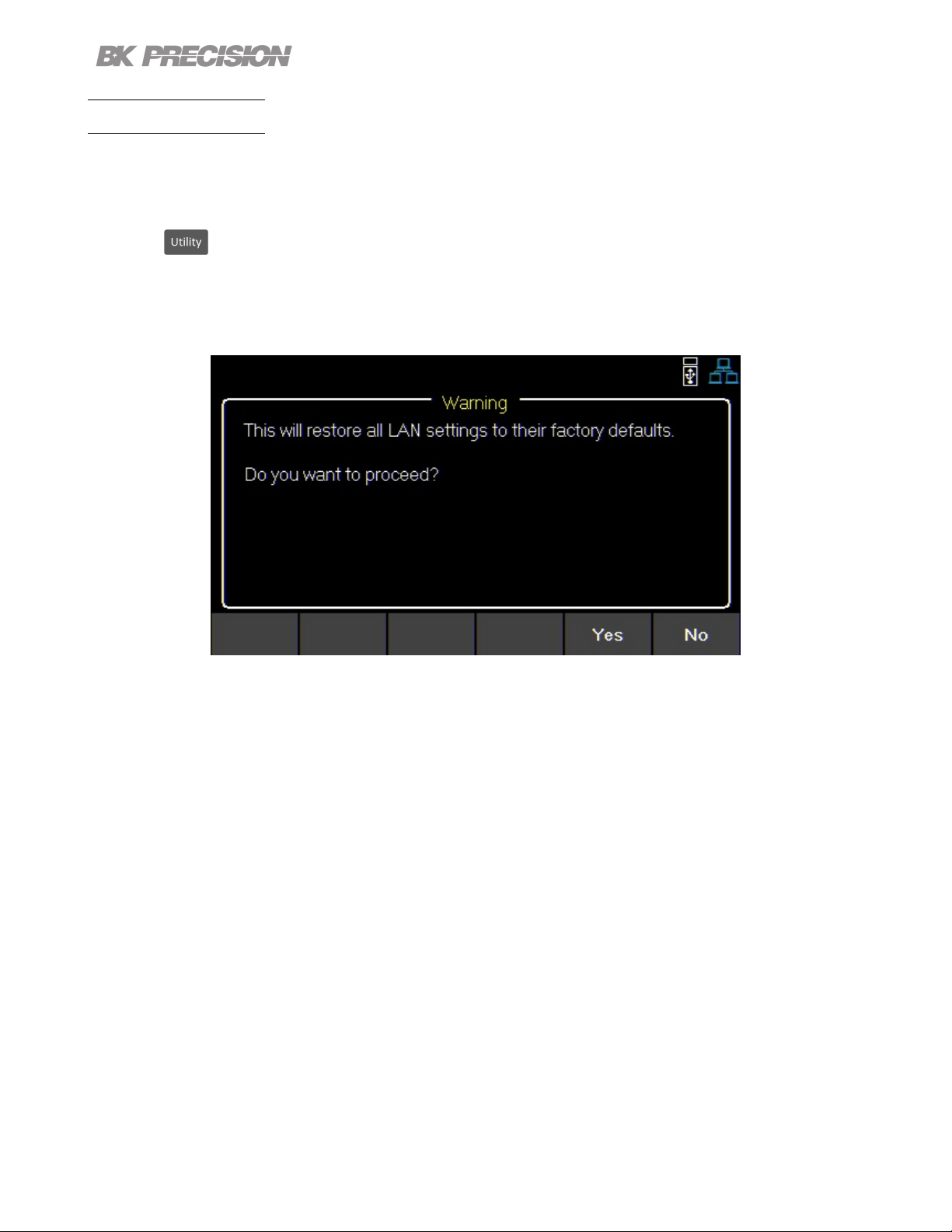
Restore Default
Restore Default will set all LAN settings to their factory defaults.
To restore factory defaults:
Press the button then use the soft key to select Utilities > I/O Cong > LAN Settings > Restore
Default .
Before restoring LAN settings to default the following warning will display.
Figure 7.5 Restore Factory Defaults
Select Yes to set to factory default.
Find Quality Products Online at: sales@GlobalTestSupply.com
www.GlobalTestSupply.com
Page 72
Utilities Menu 72
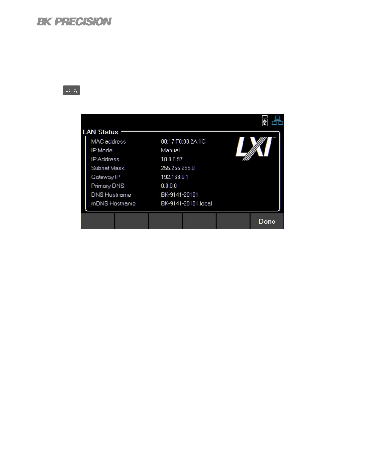
LAN Status
LAN Status provides an overview of the LAN settings.
To view the LAN status:
Press the button then use the soft key to select Utilities > I/O Cong > LAN Status .
Figure 7.6 LAN Status
Find Quality Products Online at: sales@GlobalTestSupply.com
www.GlobalTestSupply.com
Page 73

Utilities Menu 73
7.3 GPIB (optional)
In GPIB the GPIB address can be changed from 01 to 30.
To change the GPIB address:
Press the button then use the soft key to select Utilities > I/O Cong > GPIB.
Figure 7.7 GPIB Address
Use the numeric keypad to enter the new address, then press the key.
The rotary knob can also be used to set the address. must be pressed to set the new address.
Find Quality Products Online at: sales@GlobalTestSupply.com
www.GlobalTestSupply.com
Page 74

Utilities Menu 74
7.4 Digital I/O
To enter the Digital I/O menu:
Press the button then use the soft key to select Utilities > I/O Cong > Digital I/O.
Select the function and polarity of pins: 1, 2, and 3.
• Pin Functions
– None
– Digital In | Out
– Trigger In | Out
– Fault Out/Inhibit In
– Polarity Pos | Neg
• Inhibit Mode
– O
– Latched
– Live
Figure 7.8 Digital I/O Menu
Find Quality Products Online at: sales@GlobalTestSupply.com
www.GlobalTestSupply.com
Page 75

Utilities Menu 75
7.4.1 Functions
Default: None
To congure a pin:
Press the button then use the soft key to select Utilities > I/O Cong > Digital I/O > Pin(#).
None
Set selected pin to have no function.
Digital In | Out
Toggle to select In/Out digital function.
Digital In: Receive a signal from external device.
Digital Out: Send a signal to external device.
The input voltage range for digital I/O pins is 0 V to 5 V. To prevent damage to
the instrument, do not exceed 5 V or supply a negative voltage to the digital I/O pins.
Trigger In | Out
Toggle to select In/Out trigger function.
Trigger In: Receives signal that triggers set event.
Trigger Out: Sent trigger signal when specied. (BOST or EOST)
In List Mode, the Trigger In function can be used to trigger the next step when Trigger Source is set to
Digital IO.
In Datalog, the Trigger In function can be used to start/stop data logging when Trigger Source is set
to Digital IO.
Trigger Out is only available for list mode, step BOST and EOST.
Find Quality Products Online at: sales@GlobalTestSupply.com
www.GlobalTestSupply.com
Page 76
Utilities Menu 76
Fault Out
Enable a fault condition, which generates a protection fault signal on the digital port.
Dierent conditions such as over voltage, over current, or over temperature will generate a fault event.
The fault event will “disable” all outputs without turning them o.
The outputs are “disabled” by setting the outputs as low as possible.
7.4.1 Polarity
Default: Positive
Set polarity of selected pin.
Positive
A logic true signal is received as a voltage high.
Negative
A logic true signal is received as a voltage low.
7.4.1 Inhibit Mode
Receive an external input signal that controls the output state of all channels.
Default: O
To set Inhibit Mode:
1. Assign the inhibit In function to pin 3 by:
Press the button then use the soft key to select Utilities > I/O Cong > Digital I/O > Pin 3 >
Inhibit In.
2. Select Inhibit Mode: Press the button then use the soft key to select Utilities > I/O Cong >
Digital I/O > Inhibit Mode.
3. Select one of the following modes:
Note:
The following modes are only available for pin 3.
Find Quality Products Online at: sales@GlobalTestSupply.com
www.GlobalTestSupply.com
Page 77

Utilities Menu 77
O
The inhibit input is ignored.
Latched
A logic-true transition signal will disable the power supply. The output will remain disabled.
Live
Power supply output follows the state of the inhibit signal. If the inhibit signal is true the output is disabled.
When it is false the output is enabled.
7.5 Test/Admin
7.5.1 Self Test
Run a Module test.
Press the button then use the soft key to select Utilities > Test/Admin > Self-Test > Start.
Figure 7.9 Self Test Complete
7.5.2 Security
The Security Settings are locked and can be accessed by entering the default code 77416699.
Find Quality Products Online at: sales@GlobalTestSupply.com
www.GlobalTestSupply.com
Page 78

Note:
Utilities Menu 78
Figure 7.10 Security Locked
The default password can be change in the Change Code menu. If the set code is forgotten contact
B&K Precision customer support.
Use the password to gain access to the following settings.
• Change Code
• Calibrate
• Firmware Update
• NISPOM
• Lock
Find Quality Products Online at: sales@GlobalTestSupply.com
www.GlobalTestSupply.com
Page 79

Utilities Menu 79
Change Code
Changes the security code.
Press the button then use the soft key to select Utilities > Test/Admin > Security > Change
Code.
Calibrate
Enter calibration mode.
Press the button then use the soft key to select Utilities > Test/Admin > Security > Calibrate .
See chapter Calibration Adjustment Procedure to adjust the units calibration.
Firmware Update
Update the rmware and module. Press the button then use the soft key to select Utilities >
Test/Admin > Security > Firmware Update .
NISPOM
Select for complete memory wipe. Press the button then use the soft key to select Utilities >
Test/Admin > Security > NISPOM .
Lock
Sets security status to Lock. Press the button then use the soft key to select Utilities > Test/Admin
> Security > Lock .
If Done is selected without locking the security settings, the user will be prompted that the security settings
will not be locked.
7.6 Error Log
View up to 50 previously set error codes.
Press the button then use the soft key to select Utilities > Error Log.
Find Quality Products Online at: sales@GlobalTestSupply.com
www.GlobalTestSupply.com
Page 80

Utilities Menu 80
Figure 7.11 Error Log
Errors are placed in the order that they were encountered. 1 being the most recent.
The error log displays up to 50 error codes.
After reaching 50 error codes no more codes will be reported in the error log.
To continue ling error codes the error log list must be cleared
The error log can be saved into a USB ash drive connected to the USB port on the front panel.
Save the log by:
Pressing the button then use the soft key to select Utilities > Error Log > Save .
Use the rotary knob and the button to navigate through the le path of the USB. Once the desired
location has been found select Save by pressing the softkey furthest to the left.
Clear the data log by:
Pressing the button then use the soft key to select Utilities > Error Log > Clear All > Yes.
Code Description
0x0001 Over Voltage Protection Triggered
0x0002 Over Current Protection Triggered
0x0004
0x0008 Sense not connected
Table 7.1 Status Code
Over Temperature
Protection Triggered
Find Quality Products Online at: sales@GlobalTestSupply.com
www.GlobalTestSupply.com
Page 81

7.7 Help
To enter the Help menu:
Press the button then use the soft key to select Utilities > Help.
Utilities Menu 81
Figure 7.12 Help Menu
Use the rotary knob to navigate the help options shown in gure 7.12.
To select the Quick help topic press the key or press the Select softkey.
System Info
To view the instrument’s general information:
Press the button then use the soft key to select Utilities > Help > System Info.
Figure 7.13 System Info
Find Quality Products Online at: sales@GlobalTestSupply.com
www.GlobalTestSupply.com
Page 82

Utilities Menu 82
7.8 On Screen Help
Press and hold any soft key that selects a menu branch for 3 seconds to receive an explanation of what
can be found in that branch.
Find Quality Products Online at: sales@GlobalTestSupply.com
www.GlobalTestSupply.com
Page 83

Key Lock
Lock all front panel keys including and .
Press the button then use press and hold the soft keys Key Lock for 3 seconds.
Figure 8.1 Key Lock
If Key Lock Output is enabled, holding Key Lock for 3 seconds locks all front panel keys except
and . See section 7.1.1 to enable/disable Key Lock Output.
To unlock the front panel use the softkey to select Unlock.
Find Quality Products Online at: sales@GlobalTestSupply.com
www.GlobalTestSupply.com
Page 84

Save/Recall
Save/Recall the instruments Output Settings and Power-On Settings.
9.1 Save the Output Settings
Save to Internal Memory
Save the instrument’s output settings to the internal memory. A total of 10 (0 to 9) output settings can be
saved.
To save the output settings :
Press the button then use the soft keys to select Save > Save to INT.
Using the numeric keypad enter a number from 0 to 9 to save the output settings to that address.
The settings will be saved after a short delay.
Figure 9.1 Save to Internal Storage
Save to USB
Save the instrument’s output settings to a USB ash drive connected to the front panel USB host port.
Press the button then use the soft keys to select Save > Save to USB.
Find Quality Products Online at: sales@GlobalTestSupply.com
www.GlobalTestSupply.com
Page 85

Save/Recall 85
Using the rotary knob navigate through the le paths of the USB. Use the button to expand folders.
Once the desired location has been found press Save.
The output settings will be saved after a short delay.
Figure 9.2 Save to USB
9.2 Recall the Instrument’s Settings
Recall previously saved output settings from the internal memory. A total of 10 (0 to 9) user settings can
be saved.
To recall settings :
Press the button then use the soft keys to select Recall > Recall from INT.
Use the numeric keypad to enter a number from 0 to 9 to recall the output settings stored in that address.
The settings will be recalled after a short delay.
Recall from USB
Recall the instrument’s output settings from a USB drive.
Press the button then use the soft keys to select Recall > Recall from USB.
Use the rotary knob to navigate through the le paths of the USB. Use the button to expand folders.
Once the desired location has been found press Load.
The settings will be recalled after a short delay.
Find Quality Products Online at: sales@GlobalTestSupply.com
www.GlobalTestSupply.com
Page 86
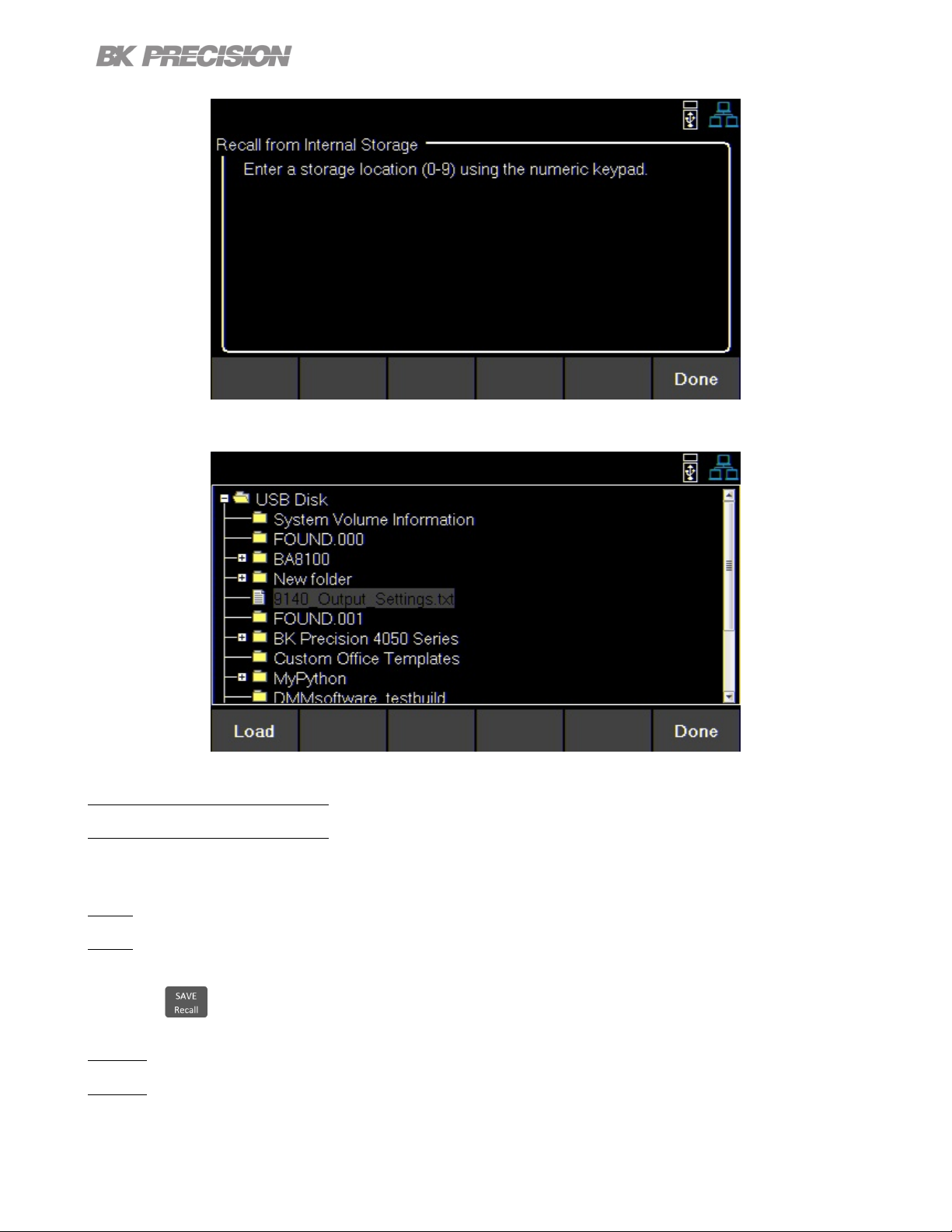
Figure 9.3 Recall from Internal Memory
Save/Recall 86
Figure 9.4 Recall from USB
9.3 Power-On Settings
Load previously saved output parameters on power-on.
O
To turn o Power-On Mode:
Press the button then use the soft keys to select Power-On Settings > Power- On Mode > O.
Last
To set the output parameters to the previous parameters before powering-o the instrument: Press the
Find Quality Products Online at: sales@GlobalTestSupply.com
www.GlobalTestSupply.com
Page 87

Save/Recall 87
button then use the soft keys to select Power-On Settings > Power- On Mode > Last.
User
To set the output parameters previously saved parameters:
• Press the button then use the soft keys to select Power-On Settings > Power- On Mode >
User.
• Press the button then use the soft keys to select Power-On Settings > User Settings.
• Use the numeric keypad or the rotary knob to assign an address (0 to 9).
To save settings see 9.1.
Default Values and Ranges
Set the instrument’s output settings to default.
Press the button then use the soft keys to select Set to Default.
9.4 Screenshot
To take a screenshot:
Press + together for 3+seconds until you hear a beep.
A USB must be plugged in for this function.
Find Quality Products Online at: sales@GlobalTestSupply.com
www.GlobalTestSupply.com
Page 88
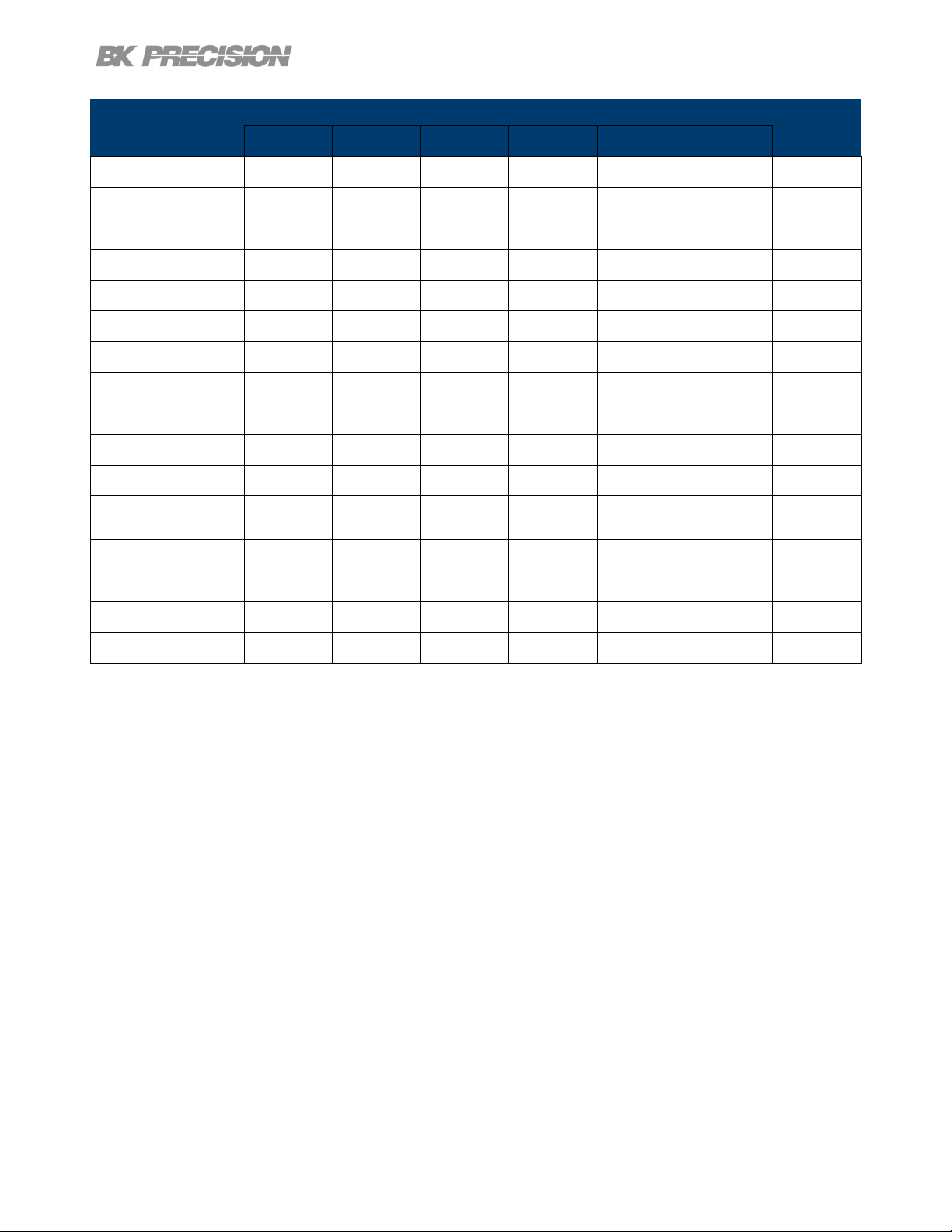
Save/Recall 88
Parameter
9140 9141
Default Max Min Default Max Min
VSET 0 32.32 0 0 60.6 0 V
ISET 1 8.08 .015 1 4.04 .015 A
Vmax 32.32 32.32 0 60.6 60.6 0 V
Vmin 0 32.32 0 0 60.6 0 V
Vslew 1600 3200 0.001 600 3000 0.001 V/s
Islew 500 800 1 100 200 1 A/s
OVP Limit 35.2 35.2 0 66 66 0.000 V
OCP Limit 8.8 8.800 0.015 4.4 4.4 0.015 A
Timer 0 99:59:59 0 0 99:59:59 0 HH:MM:SS
On Delay 0 3600 0 0 3600 0 Sec
O Delay 0 3600 0 0 3600 0 Sec
Datalogger
Sampling Interval
List Dwell 0.1 9999 0.1 0.1 9999 0.1 Sec
0.2 300 0.200 0.2 300 0.2 Sec
Unit
List Voltage 1 96.96 0 1 181.8 0 V
List Current .015 24.24 .015 .015 12.12 .015 A
List Repeat 0 100000 0 0 100000 0
Table 9.1 Default Values & Ranges
Find Quality Products Online at: sales@GlobalTestSupply.com
www.GlobalTestSupply.com
Page 89

Calibration Adjustment Procedure
Calibration Interval
The recommended calibration interval for the 9140 series is one year.
To enter the Calibration Menu:
Press the button, then use the soft key to select Utilities > Test/Admin > Security > Calibrate.
In the Calibration Menu use the softkeys to select a parameter from the menu to calibrate.
• Voltage
• Current
• OVP
• OCP
• RTC
Figure 10.1 Calibration Parameters
Find Quality Products Online at: sales@GlobalTestSupply.com
www.GlobalTestSupply.com
Page 90

Calibration Adjustment Procedure 90
10.1 Voltage Calibration Adjustment
For the voltage calibration procedure a precise DMM will be needed.
To adjust the voltage calibration:
1. Enter the Calibration Menu
• Press the button, then use the soft key to select Utilities > Test/Admin > Security.
Use the numeric keypad to enter security code. See the subsection Security. Press the
button to enter the security menu.
2. Use the softkeys to select Voltage > CH {1 |2 |3}.
3. Verify the correct channel is chosen.
• The upper left corner will display the chosen channel. Voltage Calibration will have a frame with
the color corresponding to the chosen channel.
– Yellow = CH 1
– Blue = CH 2
– Orange = CH 3
4. Connect the DMM’s voltage input to the power supply’s binding post corresponding to the selected
channel.
5. Use the softkey to select Start.
6. Use the numeric keypad to enter the measured voltage. Press the button to congure the point.
7. Repeat step 6 for the remaining calibration points.
– Upon entering the last calibration point value the display will return to the channel selection screen.
8. Repeat steps 2 through 7 to calibrate the remaining channels.
Find Quality Products Online at: sales@GlobalTestSupply.com
www.GlobalTestSupply.com
Page 91

Calibration Adjustment Procedure 91
10.2 Current Calibration Adjustment
For the current calibration procedure a precise DMM will be needed.
To adjust the current calibration:
1. Enter the Calibration Menu
• Press the button, then use the soft key to select Utilities > Test/Admin > Security.
Use the numeric keypad to enter security code. See the subsection Security. Press the
button to enter the security menu.
2. Use the softkeys to select Current > CH {1 |2 |3}.
3. Verify the correct channel is chosen.
• The upper left corner will display the chosen channel. Current Calibration will have a frame with
the color corresponding to the chosen channel.
– Yellow = CH 1
– Blue = CH 2
– Orange = CH 3
4. Connect the DMM current input to the power supply’s binding post corresponding to the selected
channel.
Note:
Upon entering a calibration point the unit will immediately output the next current point.
To avoid blowing the DMM’s fuse ensure the correct DMM’s input is chosen.
The points’ output are as follows:
9140
1st Point 0.4 A
2nd Point 2.8 A
3rd Point 5.5 A
4th Point 8.0 A
9141
1st Point 0.2 A
2nd Point 1.4 A
3rd Point 2.7 A
4th Point 4.0 A
Find Quality Products Online at: sales@GlobalTestSupply.com
www.GlobalTestSupply.com
Page 92

Calibration Adjustment Procedure 92
5. Use the softkey to select Start.
6. Use the numeric keypad to enter the measured current. Press the button to congure the point.
7. Repeat step 6 for the remaining calibration points.
– Upon entering the last calibration point value the display will return to the channel selection screen.
8. Repeat steps 2 through 7 to calibrate the remaining channels.
10.3 OVP Calibration Adjustment
For the over voltage protection calibration the instrument’s voltage must be calibrated.
To adjust the OVP calibration:
1. Enter the Calibration Menu
• Press the button, then use the soft key to select Utilities > Test/Admin > Security.
Use the numeric keypad to enter security code. See the subsection Security. Press the
button to enter the security menu.
2. Use the softkeys to select OVP > CH {1 |2 |3}.
3. Verify the correct channel is chosen.
• The upper left corner will display the chosen channel. OVP Calibration will have a frame with the
color corresponding to the chosen channel.
– Yellow = CH 1
– Blue = CH 2
– Orange = CH 3
4. Connect the DMM’s voltage input to the power supply’s binding post corresponding to the selected
channel.
5. Use the softkey to select Start.
6. Calibration State will show as Busy. After a few seconds the calibration will be adjusted on its own.
7. Upon successfully completing the calibration adjustment a dierent channel can be selected.
8. Repeat steps 2 through 6 to calibrate the remaining channels.
Find Quality Products Online at: sales@GlobalTestSupply.com
www.GlobalTestSupply.com
Page 93

Calibration Adjustment Procedure 93
10.4 OCP Calibration Adjustment
For the over current protection calibration the instrument’s current must be calibrated.
To adjust the OCP calibration:
1. Enter the Calibration Menu
• Press the button, then use the soft key to select Utilities > Test/Admin > Security.
Use the numeric keypad to enter security code. See the subsection Security. Press the
button to enter the security menu.
2. Use the softkeys to select OCP > CH {1 |2 |3}.
3. Verify the correct channel is chosen.
• The upper left corner will display the chosen channel. OCP Calibration will have a frame with the
color corresponding to the chosen channel.
– Yellow = CH 1
– Blue = CH 2
– Orange = CH 3
4. Connect the DMM’s 10 A input to the power supply’s binding post corresponding to the selected
channel.
5. Use the softkey to select Start.
6. Calibration State will show as Busy. After a few seconds the calibration will be adjusted on its own.
7. Upon successfully completing the calibration adjustment a dierent channel can be selected.
8. Repeat steps 2 through 6 to calibrate the remaining channels.
Find Quality Products Online at: sales@GlobalTestSupply.com
www.GlobalTestSupply.com
Page 94

Calibration Adjustment Procedure 94
10.5 RTC Calibration Adjustment
To adjust the Real-Time Clock(RTC) calibration:
1. Enter the Calibration Menu
• Press the button, then use the soft key to select Utilities > Test/Admin > Security.
Use the numeric keypad to enter security code. See the subsection Security. Press the
button to enter the security menu.
2. Use the softkeys to select RTC.
3. Use the softkey to select Start.
4. Calibration State will show as Busy. The calibration will be adjusted on its own in about 4 to 5 mins.
5. Calibration State will show as Success once the calibration has nished.
Find Quality Products Online at: sales@GlobalTestSupply.com
www.GlobalTestSupply.com
Page 95

Performance Verication
Performance verication ensures the instrument will meet specications listed in the datasheet.
Load regulation can be tested for both the front and rear outputs.
Note:
All specications apply to the unit after a temperature stabilization time of 15 minutes over an ambient
temperature range of 23 °C ± 5 °C. Specications are valid for single unit operation only.
CV Load Regulation Front Panel Output
1. Turn o the power supply before making any connections.
2. Connect the: DMM, electronic load, and the rear panel remote sense to the power supply’s terminal
being tested.
(Remote sense must correspond with the channel being tested.)
Figure 11.1 Front Panel Wiring Diagram
Find Quality Products Online at: sales@GlobalTestSupply.com
www.GlobalTestSupply.com
Page 96

Performance Verication 96
Note:
Keep all cables as short as possible.
3. Turn on the power supply.
4. Set the power supply settings of the channel being tested to the values given in table 11.1.
5. Set the electronic load settings to the stated values in table 11.1.
6. Enable remote sense. See section Remote Sense.
7. Enable the channel output.
8. Enable the electronic load. Monitor the power supply to ensure it remains in CV mode.If the power
supply switches to CC slightly lower the current on the electronic load until the power supply return
to CV mode.
9. Give the power supply some time to settle and record the DMM reading as V load.
10.Disable the electronic load and record the DMM reading as V noload.
11.Take the dierence between V load and V noload (V load - V noload) and record the value as the
voltage regulation. The dierence should be within the specication limit.
CV Load Regulation Rear Panel Output
1. Turn o the power supply before making any connections.
2. Connect the: DMM, electronic load, and the rear panel remote sense to the power supply’s rear +/terminal being tested.Use jumpers to connect the +S to + and -S to -. See gure 11.2
(Remote sense must correspond with the channel being tested.)
3. Turn on the power supply.
4. Set the power supply settings of the channel being tested to the values given in table 11.1.
5. Set the electronic load settings to the stated values in table 11.1.
6. Enable remote sense. See section Remote Sense.
7. Enable the channel output.
Find Quality Products Online at: sales@GlobalTestSupply.com
www.GlobalTestSupply.com
Page 97

Performance Verication 97
Figure 11.2 Rear Panel Wiring Diagram
8. Enable the electronic load. Monitor the power supply to ensure it remains in CV mode.If the power
supply switches to CC slightly lower the current on the electronic load until the power supply return
to CV mode.
9. Give the power supply some time to settle and record the DMM reading as V load.
10.Disable the electronic load and record the DMM reading as V noload.
11.Take the dierence between V load and V noload (V load - V noload) and record the value as the
voltage regulation. The dierence should be within the specication limit.
Model
Voltage Current
9140 32.000 V 3.069 A Enabled CC 3.065 A - 6.2 mV + 6.2 mV
9141 60.000 V 1.666 A Enabled CC 1.650 A - 9 mV + 9 mV
Remote
Sense
Table 11.1
Load Settings
Mode Current Lower Limit Upper Limit
Power Supply Settings Electronic
Load Regulation Limit
Find Quality Products Online at: sales@GlobalTestSupply.com
www.GlobalTestSupply.com
Page 98

Specications
Find Quality Products Online at: sales@GlobalTestSupply.com
www.GlobalTestSupply.com
 Loading...