

Page 1

Data Sheet
Handheld Digital Storage Oscilloscopes
2510 Series
The 2510 Series handheld digital storage
oscilloscopes provide floating measurement
and recorder capabilities with a built-in digital
multimeter (DMM), all in one portable and
lightweight package. These versatile 60 MHz
and 100 MHz bandwidth scopes offer 1 GSa/s
sample rates, 2 Mpts waveform memory, 32
automatic measurements, and multiple recording
functions to capture transient or long-term signal
behavior.
The built-in 6000-count multimeter allows users
to quickly switch over from an oscilloscope to a
DMM to measure DC/AC voltage and current,
resistance, and capacitance, including diode and
continuity tests.
These handheld scopes feature many useful
recording functions such as trend plot, which
allows data logging from the scope or
multimeter. Additionally, the scope recorder
function offers users 7 Mpts record length on
a single channel or 3.5 Mpts on dual channel.
The 2510 Series handheld oscilloscopes are
ideal for industrial applications, power systems,
electronics design, and field test and service.
Model 2511 2512 2515 2516
Bandwidth 60 MHz 100 MHz 60 MHz 100 MHz
Features and Benefits
■ 60 MHz (2511/2515) and 100 MHz
(2512/2516) bandwidth
■ 1 GSa/s sample rate
■ Deep waveform memory up to 2 Mpts
■ 2 fully isolated and floating 1,000 V CAT II,
600 V CAT III rated inputs (isolated models
2515 and 2516)
■ 300 V CAT II rated inputs (non-isolated
models 2511 and 2512)
■ Built-in 6000-count DMM with dedicated
terminals for current measurement
■ Scope and meter trend plot functions for data
logging
■ Bright 5.7” color display
■ Compact and lightweight – 3.4 lbs (1.54 kg)
■ FFT including four additional math functions -
Add, Subtract, Multiply, and Divide
■ 32 automatic measurements
■ USB host port for saving and recalling
waveform setups, data, and
screenshots on a USB flash drive
■ Software provided for remote PC control
■ Advanced tools include digital filters with
adjustable limits, scope and waveform
recorder mode
■ Multi-language user interface
■ Up to four hours of continuous battery
operation
Technical data subject to change
© B&K Precision Corp. 2014
Channels 2 non-isolated 2 fully isolated
Typical Applications General electronics Power electronics and industrial
www.bkprecision.com
Page 2

Handheld Digital Storage Oscilloscopes
2510 Series
Front Panel
Top View
5.7” color display
Scope and meter
mode buttons
Recorder function button
Use the scope recorder or trend
plot functions to log oscilloscope
or multimeter measurements.
Trigger menu button
Scope input terminals
Á
Durable rubber bezel
Provides grip and protection
against accidental bumps.
Auto setup
Vertical, horizontal, and trigger
controls are automatically adjusted
for fast signal display.
CH2 selection button
CH1 selection button
CH1 vertical controls
Horizontal controls
Multimeter input terminals
Dedicated terminals provided for
current measurements.
Mini USB device port
Compensate your probe or
enable remote control from a PC.
USB host port
Connect your USB flash drive to
conveniently store and recall waveform
data, setups, and screenshots.
CH2 vertical controls
USB ports
Á
Side View
DC power
adapter input
2
www.bkprecision.com
Page 3
Handheld Digital Storage Oscilloscopes
2510 Series
The tools you need
2 Mpts Deep Memory
See more details in your waveform with deep
memory. When enabled, waveforms can be
captured in high resolution while maintaining a
high sample rate over a wider period of time than
other comparable scopes.
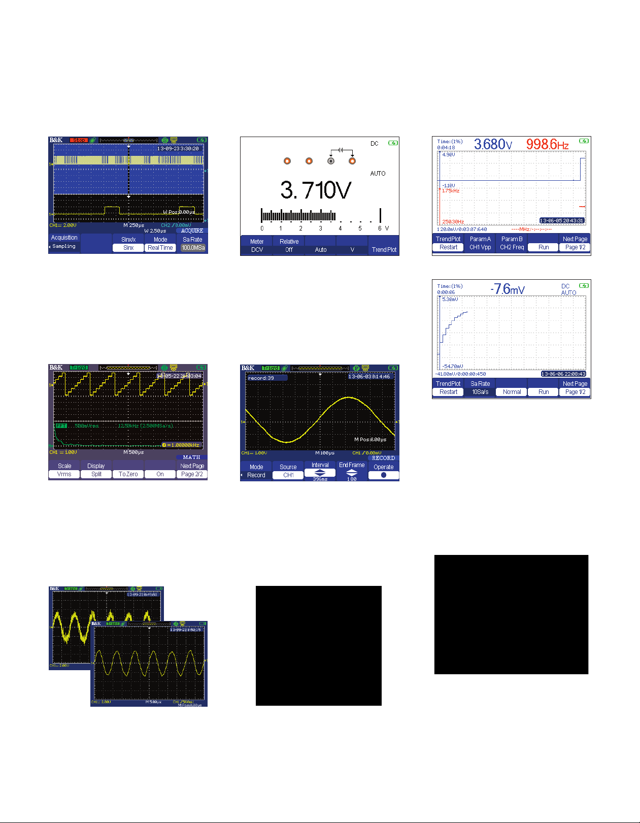
Powerful Measurement Functions
Display and measure the input signal’s frequency
spectrum. Select one of the 4 FFT windows:
Rectangular, Hanning, Hamming, and Blackman.
Use cursors to measure the spectral component’s
magnitude and frequency.
Built-in Digital Multimeter
Speed up troubleshooting with the built-in 6000-count
multimeter. Measurement functions include AC/DC
voltage and current, resistance, capacitance, diode, and
continuity test.
Scope and Waveform Recorder Modes
Monitor and analyze long-term signal behavior by
recording data continuously over a period of time.
These modes allow recorded data to be played back
for post acquisition analysis.
Scope and Meter Trend Plot Functions
Scope Trend Plot
Meter Trend Plot
Capture intermittent errors in your system.
The trend plot function can be used with the
oscilloscope or built-in DMM to plot measurement
values over time. Up to two voltage or time
parameters can be selected by the scope, and any
one of the multimeter’s measurement functions
can be graphed. These data points can then be
exported to a CSV file for further analysis.
PC Connectivity
Digital Filtering
Filter out unwanted signal components such as
various types of noise with built-in digital filters.
Choose from Low-Pass, High-Pass, Band-Pass,
and Band-Stop filters.
3
Portable Operation
Quickly troubleshoot in the field using battery
powered operation. Built for portability, the 2510
Series handheld digital oscilloscopes are rugged,
compact, and lightweight. Models 2515 and 2516
come standard with travel hard case for safe
transport on the road.
PC software provided (free download from
www.bkprecision.com) for seamless integration
between the oscilloscope and PC. Capture and
transfer waveforms, screen images, setups and
measurement results to a Windows PC via the USB
device port on the side of the instrument. A USB
host port is also available for quick and easy screen
saving.
www.bkprecision.com
Page 4

Handheld Digital Storage Oscilloscopes
2510 Series
Floating and Differential Measurements
Many industrial applications such as power electronics require measurements of high voltages and currents
that are not referenced to ground. This poses an issue with traditional line-powered oscilloscopes, which
typically have signal common connected to the chassis of the oscilloscope. This means all measurements
must be made relative to earth ground, preventing users from making differential measurements where none
of the test points are referenced to ground.
As a workaround, some people choose to float an oscilloscope by removing the connection between the
instrument's chassis and power line ground. Floating a scope is not recommended as it can put the user
at a safety risk. Parasitic capacitance is also induced in the measurement which can cause ringing and
invalidate the measurement. The 2510 Series allows engineers and technicians to make accurate and safe
measurements when the signal reference is floating.
Fully Isolated Channel Design for Safe Measurements (models 2515/2516 only)
Models 2515 and 2516 offer two CAT III 600 V
input channels for floating measurements and
feature an electrically isolated circuit design
between inputs and the digital acquisition circuit.
Isolating the ground references eliminate ground
loops and help reduce channel noise and crosstalk.
Safety Rated High Bandwidth
Oscilloscope Probes
Probe Model PR250SA
Probe Model PR150SA
All 2510 Series models come standard with high
bandwidth, safety certified passive probes (one per
channel) to help you get the most out of your
scope.
Model Included Probes
2515/2516 block diagram
2511
2512
2515
2516
Two 150 MHz bandwidth, x1/x10
probes rated for 300 V CATII
measurements
Two touch-protected 250 MHz bandwidth,
x10 probes rated for 1000 V CATII,
600 V CATIII measurements
Input Signal and Float Voltage Safety Ratings
Model 2511 / 2512 2515 / 2516
Maximum signal input safety rating with included probe 300 Vrms CAT II 1000 Vrms CAT II, 600 Vrms CAT III
Maximum signal input safety rating without probe 300 Vrms CAT II 300 Vrms CAT II
Maximum reference floating safety rating 30 Vrms 1000 Vrms CAT II, 600 Vrms CAT III
4
www.bkprecision.com
Page 5

Handheld Digital Storage Oscilloscopes
2510 Series
Digital Storage Oscilloscope Specifications
Models 2511 2512 2515 2516
Performance Characteristics
Bandwidth 60 MHz 100 MHz 60 MHz 100 MHz
Real Time Sampling Rate
1 GSa/s (half-channel interleaved)
Channels 2 non-isolated 2 isolated
Rise Time < 5.8 ns < 3.5 ns < 5.8 ns < 3.5 ns
Ch-to-Ch Isolation (both
channels at same V/div setting)
Memory Depth
Deep Memory
(3)
40 kpts (half-channel interleaved)
2 Mpts (half-channel interleaved)
> 100:1 at 50 MHz
Vertical Resolution 8 bits
Vertical Sensitivity 2 mV/div – 100 V/div (1-2-5 order) 5 mV/div – 100 V/div (1-2-5 order)
DC Gain Accuracy
5 mV/div-100 V/div: ≤ ± 3 %
2 mV/div: ≤ ± 4 %
Max. BNC Input Voltage CATII 300 Vrms from BNC signal to BNC shell
(4)
Max. Input Voltage for Probe
PR250SA
PR150SA
(5)(6)
: 10x CAT III 600 V, CATII 1000 V
2 mV - 200 mV : ±1.6 V
Channel Voltage Offset Range
206 mV - 10 V : ±40 V
10.2 V - 100 V : ±400 V
Bandwidth Limit 20 MHz (-3 dB)
Horizontal Scan Range 5.0 nS/div - 50 S/div 2.5 nS/div - 50 S/div 5.0 nS/div - 50 S/div 2.5 nS/div - 50 S/div
Timebase Accuracy ± 50 ppm measured over 1 ms interval
Input Coupling AC, DC, GND
Input Impedance 1 MΩ +/- 2 % || 18 pF ± 3 pF 1 MΩ +/- 2 % || 16 pF ± 3 pF
Probe Attenuation Selectable Factors 1X, 5X, 10X, 50X, 100X, 500X, 1000X
Vertical and Horizontal Zoom Vertically or horizontally expand or compress a live or stopped waveform
I/O Interface
USB
Acquisition Modes
USB host port support USB flash drives (FAT format)
mini-USB device port for PC connectivity and probe compensation
Sampling Display sample data only
Peak Detect Capture the maximum and minimum values of a signal
Average Waveform averaged, selectable from 4, 16, 32, 64, 128, 256
Trigger System
Edge, Pulse Width, Video*, Slope, Alternative
Trigger Types
*Support signal formats: PAL/SECAM, NTSC
Trigger condition: odd field, even field, all lines, or line number
Trigger Modes Auto, Normal, Single
Trigger Coupling AC, DC, LF reject, HF reject
Trigger Source CH1, CH2
Trigger Level Range ± 6 divisions from center of display
Trigger Displacement
Pre-trigger: Memory depth / 2* sampling
Delay Trigger: 268.04 div
Pulse Width Trigger Positive slope (>, <, =), Negative slope (>, <, =), Time: 20 ns - 10 s
Slope Trigger Positive slope (>, <, =), Negative slope (>, <, =), Time: 20 ns - 10 s
Alternate Trigger
CH1 trigger type: Edge, Pulse, Video, Slope
CH2 trigger type: Edge, Pulse, Video, Slope
(1)
(1)(2)
(1)
: 1x/10x CAT II 300 V
, 500 MSa/s (per channel)
, 20 kpts (per channel)
, 1 Mpts (per channel)
5 mV/div-100 V/div: ≤ ± 3 %
5 mV - 200 mV : ±1.6 V
206 mV - 10 V : ±40 V
10.2 V - 100 V : ±400 V
5
www.bkprecision.com
Page 6

Handheld Digital Storage Oscilloscopes
2510 Series
Digital Storage Oscilloscope Specifications (cont.)
Model 2511 2512 2515 2516
Hardware Frequency Counter
Reading Resolution 1 Hz
Range DC couple, 10 Hz to MAX bandwidth
Signal Types Satisfying all trigger signals (except pulse width trigger and video trigger)
Waveform Math and Measure
Math Operation Add, Subtract, Multiply, Divide, FFT
FFT Window mode: Hanning, Hamming, Blackman, Rectangular Sampling points: 1024
Measure
Cursors
Types Voltage, Time
Measurements
Display System
Display 5.7” Color TFT, 320 x 234 resolution, 64K color
Display Contrast (Typical) 150:1
Backlight Intensity (Typical) 300 nits
Wave Display Range 8 x 12 div
Wave Display Mode Dots, Vector
Persistence Off, 1 sec, 2 sec, 5 sec, Infinite
Menu Display 2 sec, 5 sec, 10 sec, 20 sec, Infinite
Screen-Saver Off, 1 min., 2 min., 5 min., 10 min., 15 min., 30 min., 1 hr, 2 hr, 5 hr
Waveform Interpolation Sin(x)/x, Linear
Measure Display Modes Main, Window zoom, Scan, X-Y
X-Y Sampling Frequency Support 25 kSa/s - 250 MSa/s sampling rate (1-2.5-5 order)
Color Mode Normal, Invert
Environmental and Safety
Temperature
Humidity Operating: 85% RH, 104 °F (40 °C), 24 hours
Altitude Operating: 9,842.5 ft (3,000 m)
Electromagnetic Compatibility EMC Directive 2004/108/EC, EN61326:2006
Safety Low voltage directive 2006/95/EC, EN61010-1:2001
General
Storage Memory 2 reference waveforms, 20 setups, 10 waveforms
AC Adapter Power Requirements
Battery Rating 5000 mAh, 7.4 VDC
Battery Charge Time Approx. 4 hrs
Battery Operating Time Approx. 4 hrs
Dimensions (W x H x D) 6.42” x 10.21” x 2.10” (163.2 x 259.5 x 53.3 mm)
Weight Approx. 3.4 lbs (1.54 kg) including battery
(1) Half channel operation means that only Ch1 or Ch2 is active.
(2) When sampling rate is 1 GSa/s. For sampling rate ≤ 500 MSa/s, the maximum memory depth is 20 kpts.
(3) When sampling rate is < 500 MSa/s and maximum data depth mode is enabled.
(4) Probe included with models 2511 and 2512 only.
(5) Probe included with models 2515 and 2516 only.
(6) Refer to respective probe’s manual for more information on the specification.
Vpp, Vmax, Vmin, Vamp, Vtop, Vbase, Vavg, Mean, Crms, Vrms, ROVShoot, FOVShoot, RPREShoot, FPREShoot,
Rise, Fall, Freq, Prd, +Wid, -Wid, +Dut, -Dut, BWid, Phas, FRR, FRF, FFR, FFF, LRR, LRF, LFR, LFF
∆V, ∆T, 1/∆T (frequency)
Operating: 32 °F to 104 °F (0 °C to +40 °C)
Not operating: -4 °F to 158 °F (-20 °C to +70 °C)
Input: 100-240 VAC, 50/60 Hz
Output: 9V DC, 4 A
Three-Year Warranty
6
www.bkprecision.com
Page 7

Handheld Digital Storage Oscilloscopes
2510 Series
Multimeter and Recorder Specifications
■ All specifications are based on operating at temperatures 23 ± 5°C and relative humidity < 75%.
■ Accuracy is based on ± (% of reading + offset).
Multimeter
Display Resolution
DC voltage, AC voltage, resistance,
Measurement Function
Max. Input Voltage
Max. Input Current
Input Impedance
Max. Input Voltage
Between Multimeter
Input Reference
and Ground
DC Voltage
Range Resolution Accuracy
(1)
60.00 mV 10 µV ± (1 % + 15 digits)
600.0 mV 100 µV
6.000 V 1 mV
60.00 V 10 mV
600.0 V 100 mV
1000 V 1 V
AC Voltage
(2)
Range Resolution Accuracy
60.00 mV 10 µV ± (1 % + 15 digits)
600.0 mV 100 µV
6.000 V 1 mV
60.00 V 10 mV
600.0 V 100 mV
750 V 1 V
DC and AC Current
Range Resolution Accuracy
(3)(4)
60.00 mA 10 µA
600.0 mA 100 µA
6.000 A 1 mA
10.00 A 10 mA
Resistance
Range Resolution Accuracy
600.0 Ω 0.1 Ω
6.000 kΩ 1 Ω
60.00 kΩ 10 Ω
600.0 kΩ 100 Ω
6.000 MΩ 1 kΩ
60.00 MΩ 10 kΩ
6000 counts
diode, continuity, capacitance,
DC current, AC current
AC: 750 V (20 Hz - 1 kHz)
DC: 1000 V
AC: 10 A (20 Hz - 1 kHz)
DC: 10 A
10 MΩ
CAT II 600 V
CAT III 300 V
± (1 % + 5 digits)
± (1 % + 5 digits)
± (1 % + 5 digits)
± (1.5 % + 5 digits)
± (1 % + 5 digits)
Multimeter (cont.)
Capacitance
Range Resolution Accuracy
40.00 nF 10 pF ± (3 % + 10 digits)
400.0 nF 100 pF
4.000 µF 1 nF
40.00 µF 10 nF
± (4 % + 5 digits)
400.0 µF 100 nF
Diode and Continuity Measure
Diode 0 – 2 V
Continuity < 50 Ω alarm
(1) Current input terminals protected with internal 250 V rated fuse.
(2) For frequency range 20 Hz to 1 kHz.
(3) For 10 A terminal, > 6 A DC or AC rms for 10 seconds ON and 15 minutes OFF.
(4) For AC current ranges, frequency is verified for 20 Hz to 1 kHz.
Recorder
Scope Trend Plot
Display Mode Full view, Normal
Record Length 800k points, > 24 hours
Number of Channels 2
Multimeter Trend Plot
Display Mode Full view, Normal
Record Length 1.2M dots, > 24 hours
Number of Channels 1
Scope Recorder
Display Mode Full view, Normal
Max. Record Length
Single Channel: 7 M pts
Dual Channel: 3.5 M pts
Number of Channels 2
Maximum Record Size to
External Storage
4 GB, 3000 hours
Included Accessories
User manual, passive probes (one per channel), pair of DMM test leads, 7.4 V Li-ion
battery BP2510, USB cable, probe compensation connector, AC power adapter,
travel hard case LC2510 (models 2515 and 2516 only), and certificate of calibration
7
v040714
www.bkprecision.com
 Loading...