

Page 1

MANUAL
200 MHz FREQUENCY
Model 1803D
MANUAL DE INSTRUCCIONES
Modelo 1803D
COUNTER
200 MHz CONTADOR DE
FRECUENCIA
Page 2

TEST INSTRUMENT SAFETY
WARNING
Normal use of test equipment exposes you to a certain amount of danger from electrical shock because testing must sometimes be
performed where exposed high voltage is present. An electrical shock causing 10 milliamps of current to pass through the heart will stop
most human heartbeats. Voltage as low as 35 volts dc or ac rms should be considered dangerous and hazardous since it can produce a
lethal current under certain conditions. Higher voltages are even more dangerous. Your normal work habits should include all accepted
practices to prevent contact with exposed high voltage, and to steer current away from your heart in case of accidental contact with a high
voltage. Observe the following safety precautions:
1. There is little danger of electrical shock from the dc output of this power supply because it can source 60 Vdc. There are several
other possible test conditions using this power supply that can create a high voltage shock hazard:
a. If the equipment under test is the “hot chassis” type, a serious shock hazard exists unless the equipment is unplugged (just turning
off the equipment does not remove the hazard), or an isolation transformer is used.
b. If the equipment under test is “powered up” (and that equipment uses high voltage in any of its circuits), the power supply outputs
may be floated to the potential at the point of connection. Remember that high voltage may appear at unexpected points in
defective equipment. Do not float the power supply output to more than 100 volts peak with respect to chassis or earth ground.
c. If the equipment under test is “off” (and that equipment uses high voltage in any of its circuits under normal operation), discharge
high-voltage capacitors before making connections or tests. Some circuits retain high voltage long after the equipment is turned
off.
2. Use only a polarized 3-wire ac outlet. This assures that the power supply chassis, case, and ground terminal are connected to a good
earth ground and reduces danger from electrical shock.
3. Don’t expose high voltage needlessly. Remove housings and covers only when necessary. Turn off equipment while making test
connections in high-voltage circuits. Discharge high-voltage capacitors after removing power.
(continued on inside back cover)
Page 3

TABLE OF CONTENTS
page
TEST INSTRUMENT SAFETY ----------inside front cover
SPECIFICATIONS ..............................................................4
CONTROLS AND INDICATORS -------------------------- 6
OPERATING INSTRUCTIONS .......................................8
page
INSTRUMENT REPAIR SERVICE.........................10
LIMITED ONE-YEAR WARRANTY...................... 11
SPANISH MANUAL ............................................. 16
Page 4

SPECIFICATIONS
MODES/FEATURES
Gate Times 1.0 sec and 0.1 sec gates.
Displayz 7 digits
FREQUENCY CHARACTERISTICS
Range: HF 10Hz to 25MHz
VHF 10MHz TO 200MHz
Accuracy:
1.0 Sec Gate ± Time base accuracy, ± 1
count
0.1 Sec Gate ± Time base accuracy, ± 2
counts
Resolution:
1.0 Sec Gate 1Hz
0.1 Sec Gate 10Hz
INPUT CHARACTERISTICS
IMPEDANCE HF 1MΩ
VHF 50Ω
Connector BNC
Coupling D6
Sinewave Sensitivity 50mVrms, 10Hz to
200MHz
Maximum Input 3V
TIME BASE CHARACTERISTICS
Type Crystal Oscillator
Frequency 5.24288MHz
Stability ±10ppm
Temperature Stability <0.001%(10ppm),0-
500 C
Maximum Aging Rate ±l0ppm/year
4
Page 5

SPECIFICATIONS
DISPLAY CHARACTERISTICS
Display: ............................. 0.43"LEDs
Overflow Indicator: ............ OVERflow indicator (top left corner of display) lights when count exceeds 199.9999 counts.
Display Update Time:......... . 1.0 Sec Gate: 2.0 seconds. 0.1 Sec Gate: 0.2 seconds
GENE RAL
Power:
AC Adaptor ------------------------------7-10V with 500mA
Temperature Range & Humidity:
Operation ------------------------------ -. 0 to +50'C , 85%R.H.
Storage --------------------------------- -- -15'C to + 70
Dimensions (HxWxD) ------------------ -- 2.1" X 9.06" X 6.18"(54 X 230 X 157mm)
Weight ------------------------------------- -- 0.8Kgs (1.761 (lbs)
Accessories Supplied -------------------- -- Instruction Manual BNC to Clip cable
NOTE: Specifications and information are subject to change without notice. Please visit www.bkprecision.com for the most current product
information.
’C, <
-75%R.H.
5
Page 6

CONTROLS & INDICATORS
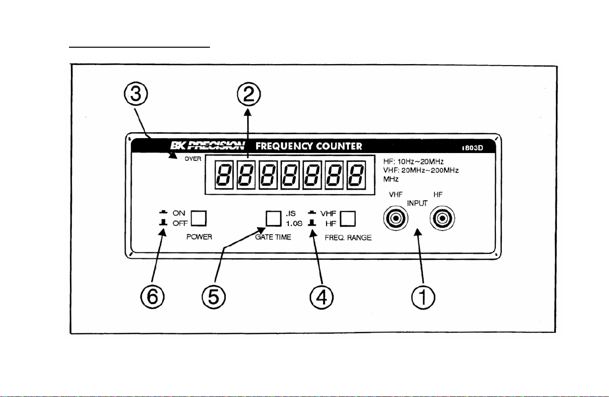
1. Input Jack. Input jack for 10Hz to 200MHz frequency measurements.
2. Display. Seven digit display used for all frequency readings.
3. OVERfIow Indicator. Lights whenever range of display is exceeded (199.99999MHz). Most significant digit is not displayed.
4. Frequency Function Switch.: Selects VHF and HF frequency range at input jack.
5. Gate Time Switch.: Selects gate time 0.1 second and 1.0 second.
6. POWER Switch: Turns power ON and OFF.
Page 7
CONTROLSAND INDICATORS
Page 8

OPERATING INSTRUCTIONS
WARNING
Some operating conditions may pose an electrical shock
hazard. Know and observe the precautions described in the
"Test Instrument Safety” section.
2. Connect the AC Adapter to an ac outlet and plug into the
rear panel jack of the frequency counter.
3. Set the POWER/GATE TIME switch to 0.IS or 1.0 S.
a. Use 0.1S for faster measurement of high frequency
signals. The update time of the display is every 0.2
second. Resolution is 10Hz.
b. Use I.OS for measurement of low frequencies or
where highest resolution is needed. The update
time of the display is every 2 seconds. Resolution
is 1Hz.
4. Apply the 10Hz to 200MHz signals to be measured to
the input jack.
CAUTION
To prevent damage to the unit, do not apply input voltage higher that the
limits listed in the "Specifications” section. Connect the instrument ground
lead only to zero volt points in the circuit under test. Attempting to "float” the
unit may result in a shock hazard, since the instrument ground is exposed at
the front panel BNC connector.
If measuring ac line frequency, observe the precautions listed in the "Line
Voltage Measurement" paragraph.
1. .Frequency is given by the front panel display. The decimal point is
automatically positioned.
a. With a 1.0S gate time, readings below 1MHz are given in decimal
MHz, above MHz, they are in whole megahertz. For example,
12KHz is displayed as.012000, and 12MHz is 12.000000.
b. With a 0.1S gate time, all readings are displayed in MHz, and with
one less digit resolution. For example, 12KHz is displayed as
0.01200, and 12MHzis 12.000000.
5. Measurement interval, or "gate time", is 1.0 second or 0. I second. This is
combined with an additional interval of equal time for internal latching
and resetting, for a total of 2 seconds between display updated when 1.0S
gate time is selected or 0.2 seconds when 0.1S gate time is selected.
6. The OVER flow indicator lights whenever the range of the display
(199.9999MHz) is exceeded.
8
Page 9

CONSIDERATIONS
Display Instability
An uncertainty of ± 1 least significant digit is inherent in all digital
measurements, and greater uncertainties can result from other
factors. For example, in low frequency measurements, high
frequency noise on the input can cause miscounting. Also,
uncertainty may be introduced by instability of the input frequency,
usually common with LC -type oscillators.
Use of Antenna
To measure transmitter frequency, it is not always necessary to have
adirect electrical connection to the transmitter. In fact, the counter
should be protected against from excessive power levels. A preferred
method of frequency measurement is to connect an antenna to the
input of the counter .The BK Precision Model AT-21 Antenna Kit is
ideal for use with the Mode1 1803D counter for measuring
frequencies from 20MHz to 200MHz. The antenna should be placed
parallel with the transmitting antenna and separate by a few inches.
The specific distance is determined by
the power level of the transmitter. Some very low power
transmitters may not provide enough signal to the counter with this
this method. An unmodulated carrier should be transmitted and the
frequency will appear on the display of the counter.
Cable Considerations
Cable connections in RF measurements should be aimed at reducing
standing waves and shunt cable capacitance, both of which can affect
measurement accuracy.
Standing waves can be minimized by matching impedances of signal
source, cable, and termination. For example, for a 50 ohm source,
use a 50 ohm cable and terminate with a 50 ohm resistive load. Both
standing waves and shunt cable capacitance can be reduced by
keeping cable lengths short, less than three feet (91cm).
9
Page 10

Service Information
Warranty Service: Please return the product in the original packaging with proof of purchase to the address below. Clearly state in writing the
performance problem and return any leads, probes, connectors and accessories that you are using with the device.
Non-Warranty Service: Return the product in the original packaging to the address below. Clearly state in writing the performance problem and
return any leads, probes, connectors and accessories that you are using with the device. Customers not on open account must include payment in
the form of a money order or credit card. For the most current repair charges please visit www.bkprecision.com and click on “service/repair”.
Return all merchandise to B&K Precision Corp. with pre-paid shipping. The flat-rate repair charge for Non-Warranty Service does not include
return shipping. Return shipping to locations in North American is included for Warranty Service. For overnight shipments and non-North
American shipping fees please contact B&K Precision Corp.
B&K Precision Corp.
22820 Savi Ranch Parkway
Yorba Linda, CA 92887
www.bkprecision.com
714-921-9095
Include with the returned instrumentyour complete return shipping address, contact name, phone number and description of problem.
10
Page 11

Limited One-Year Warranty
B&K Precision Corp. warrants to the original purchaser that its products and the component parts thereof, will be free from defects in
workmanship and materials for a period of one year from date of purchase.
B&K Precision Corp. will, without charge, repair or replace, at its option, defective product or component parts. Returned product must be
accompanied by proof of the purchase date in the form of a sales receipt.
To obtain warranty coverage in the U.S.A., this product must be registered by completing a warranty registration form on www.bkprecision.com
within fifteen (15) days of purchase.
Exclusions: This warranty does not apply in the event of misuse or abuse of the product or as a result of unauthorized alterations or
repairs. The warranty is void if the serial number is altered, defaced or removed.
B&K Precision Corp. shall not be liable for any consequential damages, including without limitation damages resulting from loss of use. Some
states do not allow limitations of incidental or consequential damages. So the above limitation or exclusion may not apply to you.
This warranty gives you specific rights and you may have other rights, which vary from state-to-state.
B&K Precision Corp.
22820 Savi Ranch Parkway
Yorba Linda, CA 92887
www.bkprecision.com
714-921-9095
14
Page 12

TEST INSTRUMENT SAFETY
(continued from inside front cover)
4. If possible, familiarize yourself with the equipment being tested and the location of its high voltage points. However, remember that
high voltage may appear at unexpected points in defective equipment.
5. Use an insulated floor material or a large, insulated floor mat to stand on, and an insulated work surface on which to place
equipment; and make certain such surfaces are not damp or wet.
6. When testing ac powered equipment, the ac line voltage is usually present on some power input circuits such as the on-off switch,
fuses, power transformer, etc. “any time” the equipment is connected to an ac outlet.
7. B+K Precision products are not authorized for use in any application involving direct contact between our product and the human
body, or for use as a critical component in a life support device or system. Here, “direct contact” refers to any connection from or to
our equipment via any cabling or switching means. A “critical component” is any component of a life support device or system
whose failure to perform can be reasonably expected to cause failure of that device or system, or to affect its safety or effectiveness.
8. Never work alone. Someone should be nearby to render aid if necessary. Training in CPR (cardio-pulmonary resuscitation) first aid
is highly recommended.
15
Page 13

SEGURIDAD DE EL INSTRUMENTO DE PRUEBA
PRECAUCIONES
Uso normal de probado de prueba te espose a cierta cantidad de peligro por un choque eléctrico porque revisiones son algunas veces hechas
donde hay alto voltaje descubierto. Un choque eléctrico que cause 10 milliamps pasar a través del corazón pararía la mayoría de los corazones
humanos. Voltaje tan bajo hasta 30 voltios dc ou ac rms podría ser considerado peligroso porque puede producir una corriente letal bajo ciertas
condiciones. Voltajes mas altos pueden ser aun mas peligrosos. Tus hábitos normales de trabajo deben de incluir todas las practicas aceptadas
para prevenir contacto con alto voltaje descubierto, y dirigir corriente lejos de el corazón en caso de contacto accidental con un alto voltaje.
Observe las siguientes medidas de seguridad:
1. Hay poco peligro de un choque eléctrico de la salida de cd de esta fuente de poder. Pero, puede haber otras posibles condiciones de prueba
que cuando usando esta fuente de poder se puede crear un peligro de un choque de alto voltaje.
Si el equipo bajo prueba es de el tipo “chasis caliente”, un serio peligro de choque existe al menos que el equipo este desconectado (
nada mas apagando el equipo no remueve el peligro), o si un transformador de aislamiento es usado.
Si el equipo bajo prueba esta “prendido” (y este equipo usa alto voltaje en cualquiera de sus circuitos), las salidas de la fuente de poder
pueden ser flotadas a el potencial al el punto de conexión. Recuerden que el alto poder puede aparecer en puntos inesperados en
equipo defectuoso. No flote la salida de la fuente de poder por mas de 100 voltios pico con respecto al chasis o tierra.
Si el equipo bajo prueba esta “apagado” (y este equipo usa alto voltaje en cualquiera de sus circuitos cuando en operación normal),
descarga alto-voltaje capacitares antes de hacer conexiones o pruebas. Algunos circuitos conservan alto voltaje mucho después que el
equipo es apagado.
2. Solo use una enchufe polarizada de 3-conductores. Esto asegura que el chasis de la fuente de poder, cubierta, y la terminal de tierra están
conectadas a una buena tierra y reduce el peligro de un choque eléctrico.
3. No se expone a alto poder innecesariamente. Remueva cubiertas solo cuando mas necesario. Apague el equipo cuando este haciendo
conexiones de prueba en circuito de alto-voltaje. Descargue los capacitadotes después de que remueva el poder.
(continua el la parte de atrás)
16
Page 14

TABLA DE CONTENIDO
page
SEGURIDAD DE EQUIPO DE PRUEBA Segunda de forros
ESPECIFICACIONES ........................................................18
CONTROLES AND INDICADORES ---------------------- 21
INSTRUCTIONES DE OPERACION .............................22
page
INFORMACION DE SERVICO............................................23
GARANTIA LIMITADA DE UN AÑO....................24
17
Page 15

Page 16

ESPECIFICACIONES
MODOS/CARACTERISTICAS
Tiempo de compuerta 1.0 sec y 0.1 seg.
Pantalla 7 digitos
CARACTERISTICAS DE FRECUENCIA
Rango: HF 10Hz a 25MHz
VHF 10MHz a 200MHz
Precisión:
Compuerta 1.0 Seg ± Precisión base de tiempo,±
1 cuenta
Compuerta 0.1 Seg ± Precisión base de tiempo,±
2 cuentas
Resolución:
Compuerta 1.0 Seg 1Hz
Compuerta 0.1 Seg 10Hz
CARACTERISTICAS DE ENTRADA
IMPEDANCIA HF 1MΩ
VHF 50Ω
Conector BNC
Acoplamiento D6
Sensitividad senoidal 50mVrms, 10Hz a
200MHz
Entrada máxima 3V
CARACTERISTICAS DE BASE DE TIEMPO
Tipo Oscilador a cristal
Frecuencia 5.24288MHz
Estabilidad ±0.lppm
Estabilidad de temperatura <0.001%(10ppm),0-
500 C
Razón de envejecimiento ±loppm/year
máximo
18
Page 17

Page 18

ESPECIFICACIONES
CARACTERIS TICAS DE PANTALLA
Pantalla:............................. 0.43"LEDs
Indicador de sobreflujo:...... Indicador OVERflow Esauina superior izquierda) enciende cuando la cuenta exceed de 199.9999.
Tiempo de actualización de pantalla: -. Compuerta 1.0 Seg: 2.0 segundos. Compuerta 0.1 Sec: 0.2 segundos
GENE RAL
Potencia:
Adaptador AC --------------------------- 7-10V con 500mA
Rango de temperatura&humedad:
Operación ------------------------------ -. 0 a +50'C , 85%R.H.
Almacenamiento --------------------- -- -15'C a + 70
Dimensiones (HxWxD) ---------------- -- 2.1" X 9.06" X 6.18"(54 X 230 X 157mm)
Peso ---------------------------------------- -- 0.8Kgs (1.761 (lbs)
Accessorios incluídos ------------------- -- Manual de usuario, Cable BNC a Clip
NOTA: Las especificaciones y la información están conforme a cambio sin el aviso de B&K Precision Corp. Por favor visite
www.bkprecision.com para las especificaciones más corriente y información de nuestros productos.
’C, <
-75%R.H.
19
Page 19

CONTROLS AND INDICATORS
7. Jack. De entrada. Entrada para mediciones de frecuencia de 10Hz a 200MHz.
8. Pantalla. De siete dígitos para todas las frecuencias.
9. OVERfIow Indicador. Enciende al excederse el rango ( 199.99999MHzNo se muestra el dígito más significativo.
10. Switch de function de frecuencia.: Seleccciona rangos de frecuencia VHF y HF en el jack de entrada
11. Switch de tiempo de compuerta.: Seleccciona tiempo de 0.1 segundo y 1.0 segundo.
12. POWER Switch: Encendido ON and OFF.
20
Page 20

CONTROLSAND INDICATORS
INSTRUCTIONES DE OPERACION
ADVERTENCIA
Algunas condiciones de operación pueden producir un riesgo
de choque eléctrico. Conozca y observe las precauciones
descritas en la sección "Seguridad del instrumento de prueba”
.
1. Conecte el adaptador de AC a un enchufe AC e insértelo
en el jack del panel trasero del contador. De frecuencia.
2. Fije el POWER/GATE TIME switch a 0.1S o 1.0 S.
a. Use 0.1S para mediciones más rápidas de
señales de alta frecuencia. El tiempo de
actualización en pantalla es de 0.2 segundos.
La resolución es de 10Hz.
b. Use 1.0S para mediciones de frecuencias bajas
o para mayor resolución. El tiempo de
actualización es de 2 seg. La resolución es de
1Hz.
3. Aplique las señal a medir al jack de entrada.
PRECAUCION
Para prevenir daños a la unidad no aplique voltajes de entrada
superiores al límite establecido en la sección de
“Especificaciones”. Conecte la tierra del instrumento sólo a
puntos de cero voltas del circuito bajo prueba . No pretenda
“flotar” la unidad pues se genera un riesgo de dado que la tierra
del instrumento está expuesta en el conector frontal BNC. Al
medir la frecuencia de la línea de AC, observe las precauciones
enlistadas en el párrafo"Medición del voltaje de línea".
4. La frecuencia se muestra en pantalla. El punto decimal se
posiciona automáticamente
a. Con un tiempo de 0.1s, lecturas menores a 1MHz
se muestran décimas de MHz ; arriba de 1MHz, se
muestran en Mhz. Por ejemplo, 12KHz se muestra
como.012000, y 12MHz como 12.000000.
b. Con un tiempo de 0.1S, todas las lecturas son en
Mhz, con un dígito menos de resolución. Por
ejemplo, 12KHz se muestra como 0.01200, y
12MHz como 12.000000.
5. El intervalo de medición “tiempo de compuerta”, es 1.0 segs.
or 0. 1 seg. Este se combina con el intervalo adicional de
igual tiempo de reajuste interno para un total de 2 segundos
entre actualización de pantalla al seleccionar 1.0S o 0.2 segs.
21
al seleccionar tiempo de compuerta de 0.1 seg.
Page 21

Page 22

CONSIDERACIONES
Inestabilidadde
pantalla
Una inestabilidad de ± 1 dígito menos significativo es
inherente en todas las mediciones digitales,y pueden existir
incertidumbres a causa de otros factores, como el ruido de
alta frecuencia en mediciones de baja frecuencia, o
inestabilidad de la frecuencia de entrada común en
osciladores del tipo LC.
Uso de antena
Para medir frecuencia de transmisores, no es siempre
necesaria una conexión directa al transmisor.. De hecho, el
contador debe protegerse contra niveles excesivos de
potencia. Se prefiere el método de conectar una antenna a la
entrada del contador.. El BK Precision Model PT - 21
Antenna Kit es ideal para usarse con el Modelo I803d para
medir frecuencias de 20MHz a 200MHz. La antena debe
colocarse en paralelo con la antenna transmisora separada
por unas cuantas pulgadas.
La distancia específica se determina por el nivel de potencia
del transmisor. Algunos transmisores de muy baja potencia
pueden no proveer una señal suficiente para la medición con
este método.; se debe transmitir una portadora no modulada
y la frecuencia aparecerá en pantalla del contador.
Consideraciones de cable
Las conexiones de cables en mediciones de alta frecuencia
deben efectuarse para reducer ondas estacionarias y eliminar
capacitancia paralelo, las cuales afectan la precisión de la
medición.
Las ondas estacionarias se minimizan pareando la
impedancia de la fuente de entrada con la del cable y la
terminación. Por ejemplo, para una fuente de 50 ohms use
cable de 50 ohms y una carga terminal resistiva de 50 ohms.
Tanto las ondas estacionarias como l capacitancia paralelo
pueden reducirse con cables cortos, de menos de 3 pies,
(91cm).
Page 23

Información de Servicio
Servicio de Garantía: Por favor regrese el producto en el empaquetado original con prueba de la fecha de la compra a la dirección debajo.
Indique claramente el problema en escritura, incluya todos los accesorios que se estan usado con el equipo.
Servicio de No Garantía: Por favor regrese el producto en el empaquetado original con prueba de la fecha de la compra a la dirección
debajo. Indique claramente el problema en escritura, incluya todos los accesorios que se estan usado con el equipo. Clientes que no tienen
cuentas deben de incluir pago en forma de queque, orden de dinero, o numero de carta de crédito. Para los precisos mas corriente visite
www.bkprecision.com y oprime “service/repair”.
Vuelva toda la mercancía a B&K Precision Corp. con el envío pagado por adelantado. La carga global de la reparación para el servicio de la
No-Garantía no incluye el envío de vuelta. El envío de vuelta a las localizaciones en norte americano es incluido para el servicio de la
garantía. Para los envíos de noche y el envío del no-Norte los honorarios americanos satisfacen el contacto B&K Precision Corp.
B&K Precision Corp.
22820 Savi Ranch Parkway
Yorba Linda, CA 92887
www.bkprecision.com
714-921-9095
Incluya con el instrumento la dirección de vuelto para envío, nombre del contacto, número de teléfono y descripción del problema.
Page 24

Garantía Limitada de Un Ano
B&K Precision Corp. Autorizaciones al comprador original que su productos y componentes serán libre de defectos por el periodo de un ano
desde el día en que se compro.
B&K Precision Corp. sin carga, repararemos o sustituir, a nuestra opción, producto defectivo o componentes. Producto devuelto tiene que ser
acompañado con prueba de la fecha del la compra en la forma de un recibo de las ventas.
Para obtener cobertura en los EE.UU., este producto debe ser registrado por medio de la forma de registro en www.bkprecision.com dentro de
quince (15) días de la compra de este producto.
Exclusiones: Esta garantía no se aplica en el evento de uso en error o abuso de este producto o el resultado de alteraciones
desautorizado o reparaciones. La garantía es vacía si se altera, se desfigura o se quita el número de serie.
B&K Precision Corp. no será obligado a dar servicio por danos consecuente, incluyendo sin limitaciones a danos resultando en perdida de
uso. Algunos estados no permiten limitaciones de daños fortuitos o consecuentes. Tan la limitación o la exclusión antedicha puede no
aplicarse a usted.
Esta garantía le da ciertos derechos y pueden tener otros derechos, cuales cambian estado por estado.
B&K Precision Corp.
22820 Savi Ranch Parkway
Yorba Linda, CA 92887
www.bkprecision.com
714-921-9095
Page 25

SEGURIDAD DE EL EQUIPO DE PRUEBA
(Continua por dentro de portada)
4. Si es posible, familiarícese con el equipo que va ha ser revisado y el lugar de los puntos de alto voltaje. Pero, recure que alto voltaje
puede aparecer en puntos inesperados en equipo defectivo
5. Use un piso de material insuflado o un largo, insuflado tapete para parase en el, y una superficie de trabajo insuflada el la cual pueda
poner el equipo; y asegurese que estas superficies no estén húmedas o mojadas.
6. Cuando este probando equipo encendido por ca, la linea de voltaje de corriente alterna esta usualmente presente en algunos de los
circuitos de entrada tal como el switch de encendido / apagado, fusibles, transformador de poder, etc. “Cualquier tiempo” que el equipo
este conectado a un enchufe de ca.
7. B & K Precision productos no estan autorizados en ninguna aplicación que incluya contacto directo entre nuestro producto y el cuerpo
humano, o para uso como un componente critico en un dispositivo o sistema de soporte de vida. Aqui, ‘contacto directo” se refiere a
cualquier conexión de o a nuestro equipo a través de cualquier cableado o mecanismo de cambio. Un “ componente critico” es un
componente de un dispositivo o sistema de soporte de vida cual falla a funcionar puede esperar razonablemente causar una falla de el
dispositivo o sistema, o afectar su seguridad o eficacia.
8. Nunca trabaje solo. Algvien debe de estar cerca para prestar ayuda si necesaria. Entrenamiento en CPR (cardio- pulmonaria
resucitación) primeros auxilios es altamente recomendado.
Page 26

Printed in Taiwan
22820 Savi Ranch Parkway
Yorba Linda, CA 92887
www.bkprecision.com
© 2007 B&K Precision Corp.
PN# 481-375-9-001
 Loading...